


flying_dutchman2
-
Posts
1,735 -
Joined
-
Last visited
Content Type
Profiles
Forums
Gallery
Events
Posts posted by flying_dutchman2
-
-
-
Thanks for all the likes, suggestions and comments.
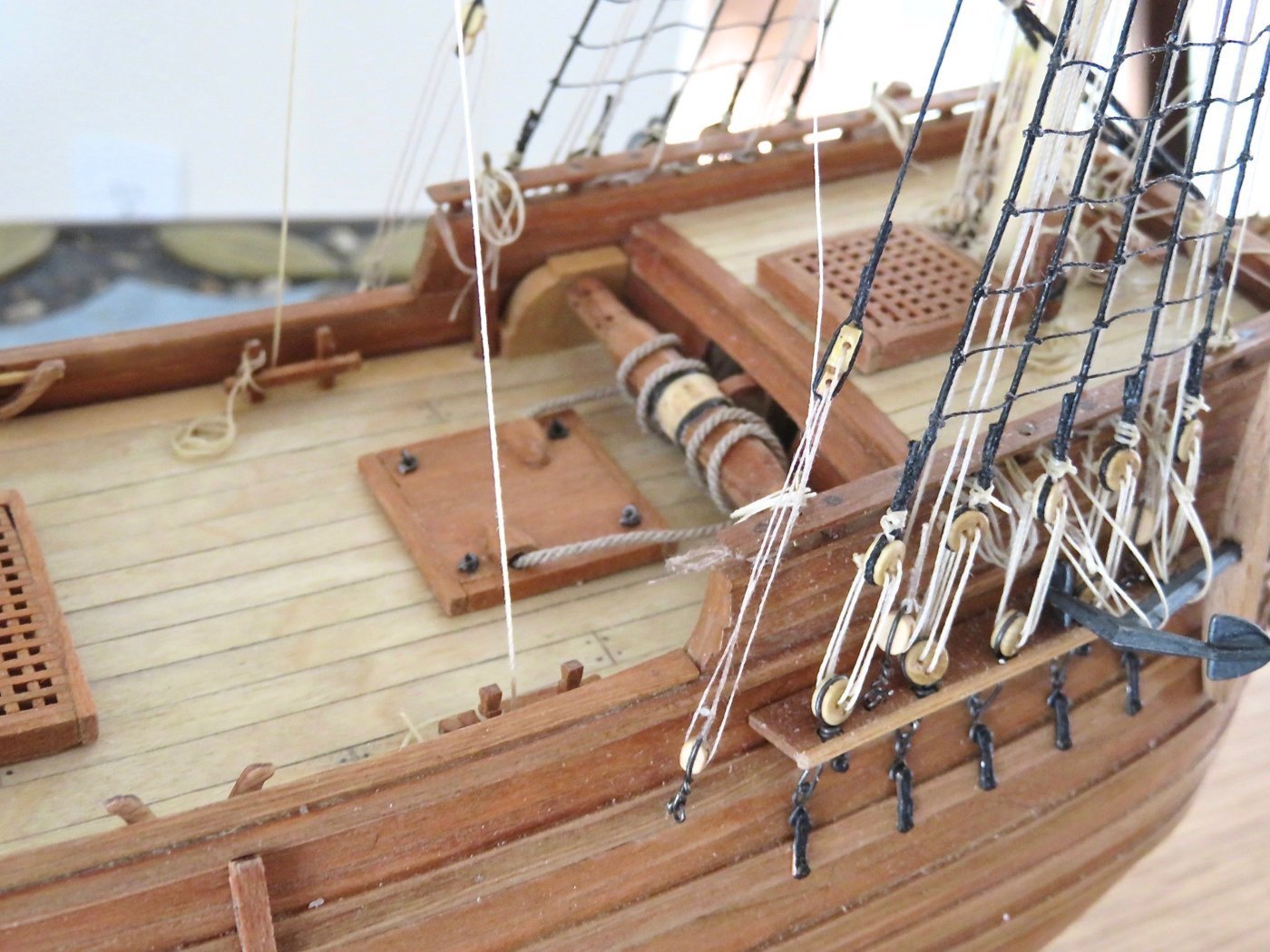
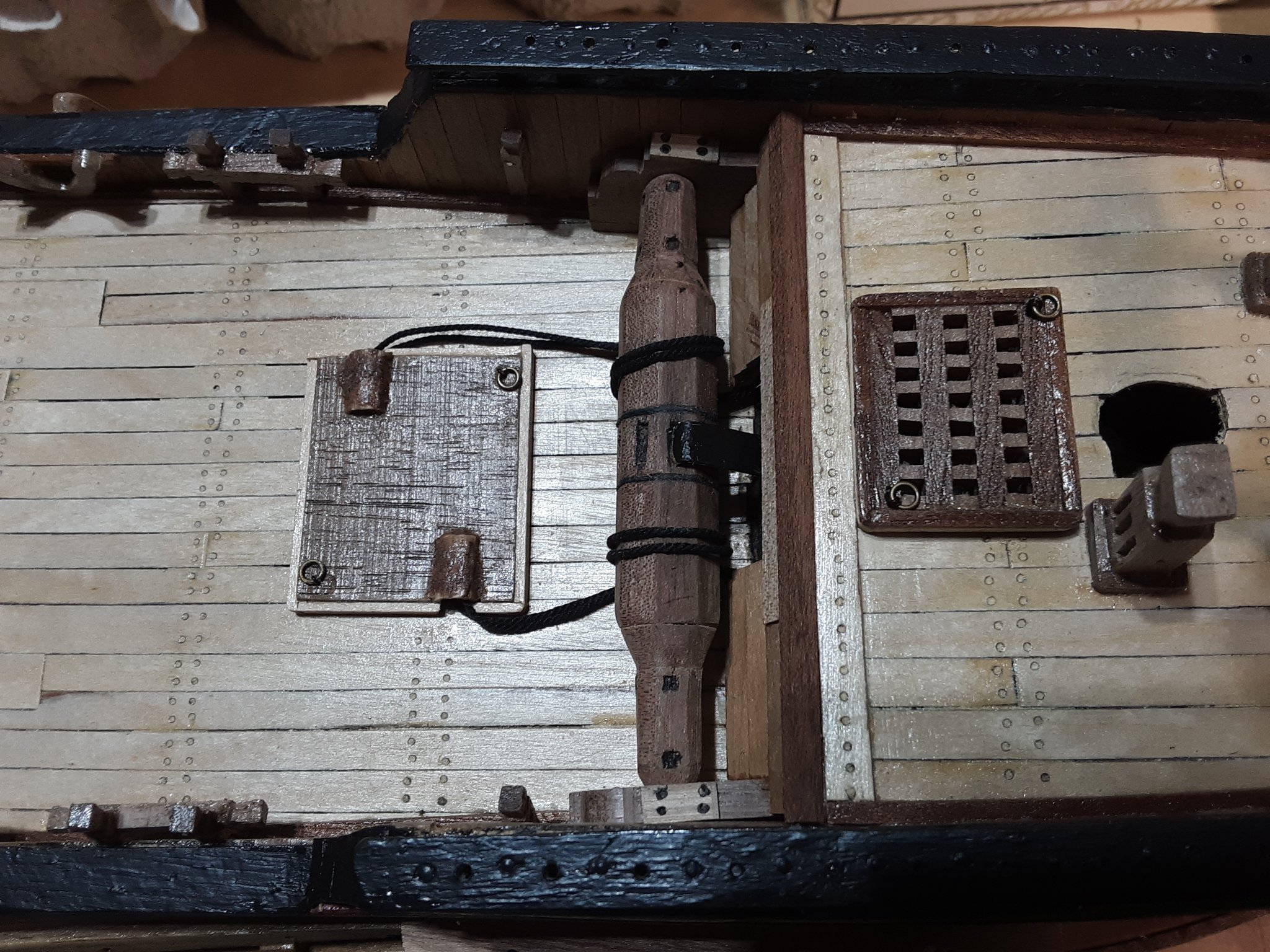
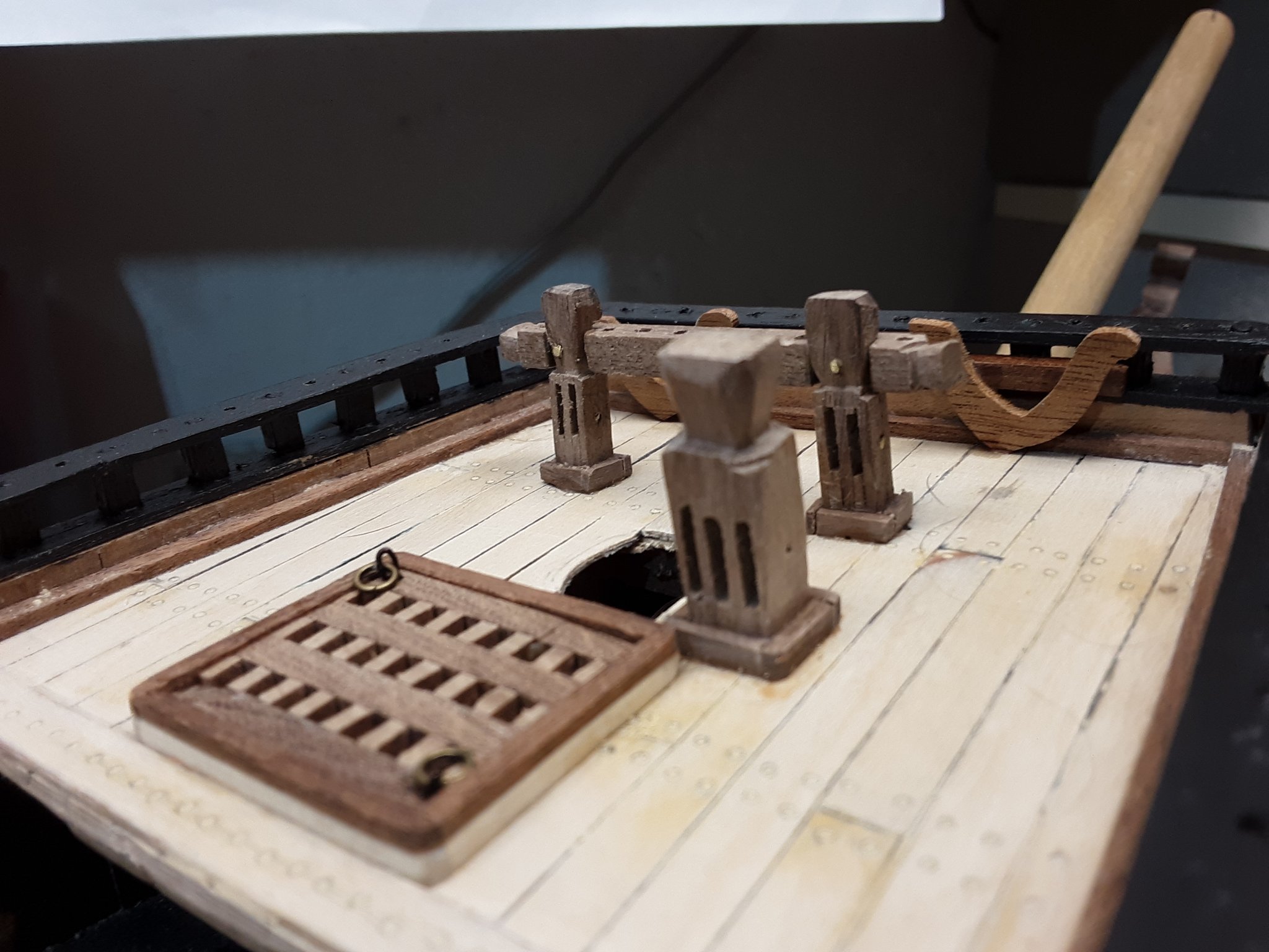
After sanding the windlass barrel, added the ratchet teeth for the pawl bit. Painted the holes matt black. Added the supporting posts on each side and installed the complete piece on the upper deck. Added the anchor rope and put the excess into the holes of the hatch cover.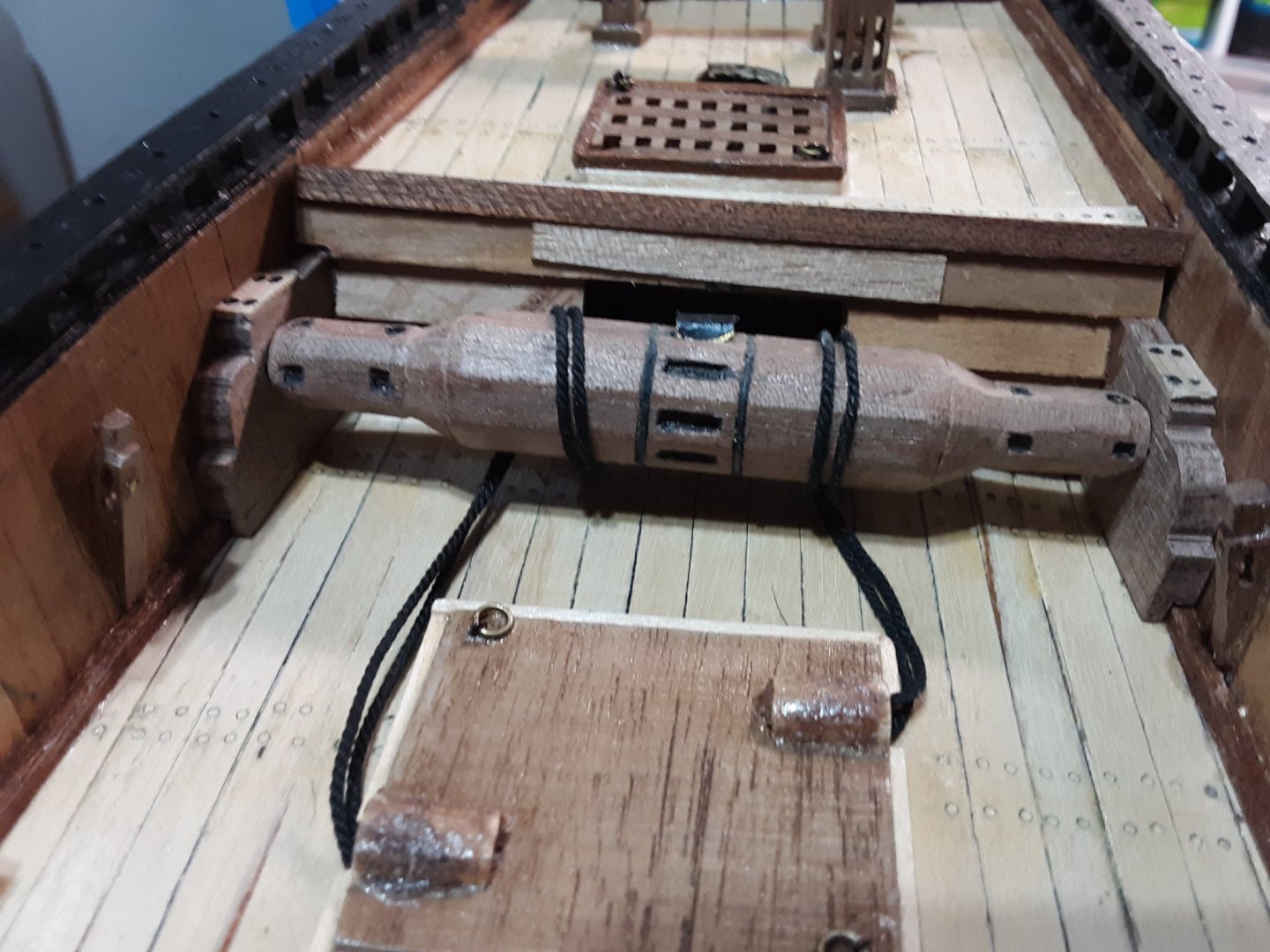

I will also add the square poles that fit into the square holes.
For a change of pace looked through the 2 mast and accessories plans en ID'd all the parts that make up the different masts. Using the measurements from the index of the book and the plans and multiplied it by 2 figured out the sizes of it all. My model is twice the size. Plans are 1:75 and model is 1:37.5. It is going to be a rather large model. I knew it was going to be big, but not "that" big. I'm not even going to think about when she is finished and where I am going to put her.
Marcus -
Hi Petr,
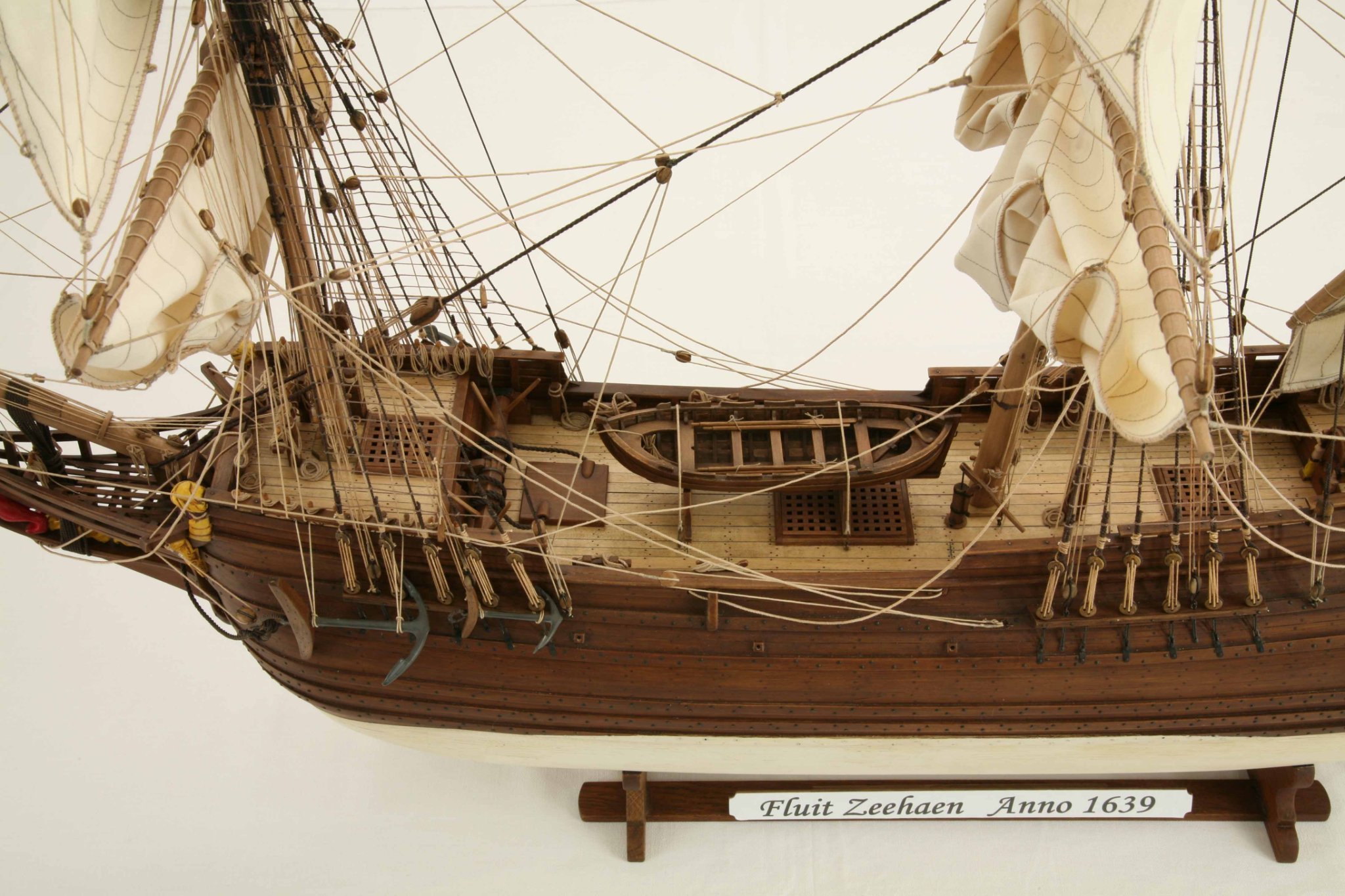
I am pulling up a chair and will follow your build with great interest. I will probably build a Pinas after I finish my fluit, the Zeehaen.
You are in good hands. Ab is extremely knowledgeable on Dutch ships, which will make building the Pinas much easier than if Ab wasn't available.
Marcus
-
7 hours ago, wefalck said:
Do you have any machine tools, specifically a lathe ? Here is building log of a colleague of mine, where he shows step by step how he makes a similar windlass: https://forum.arbeitskreis-historischer-schiffbau.de/viewtopic.php?f=16&t=2230#p28040 (not sure, whether this is visible without registering. Apologies in this case).
I have machine tools, but no lathe. I made a jig to hook up a variable speed drill in it and that is my ersatz lathe.
I need to register to read it, so I will register and practice my German ☺️
Marcus
-
-
As I look at your excellent and meticulous work on your sails, I look at my sails on the Boyer and the Utrecht and we do pretty much the same details. I do all the sewing by hand using many Dutch books for that particular era of the ship I am building.
Sails for the Fluit will be much simpler.
Marcus
-
Thanks for all the likes, suggestions and comments.
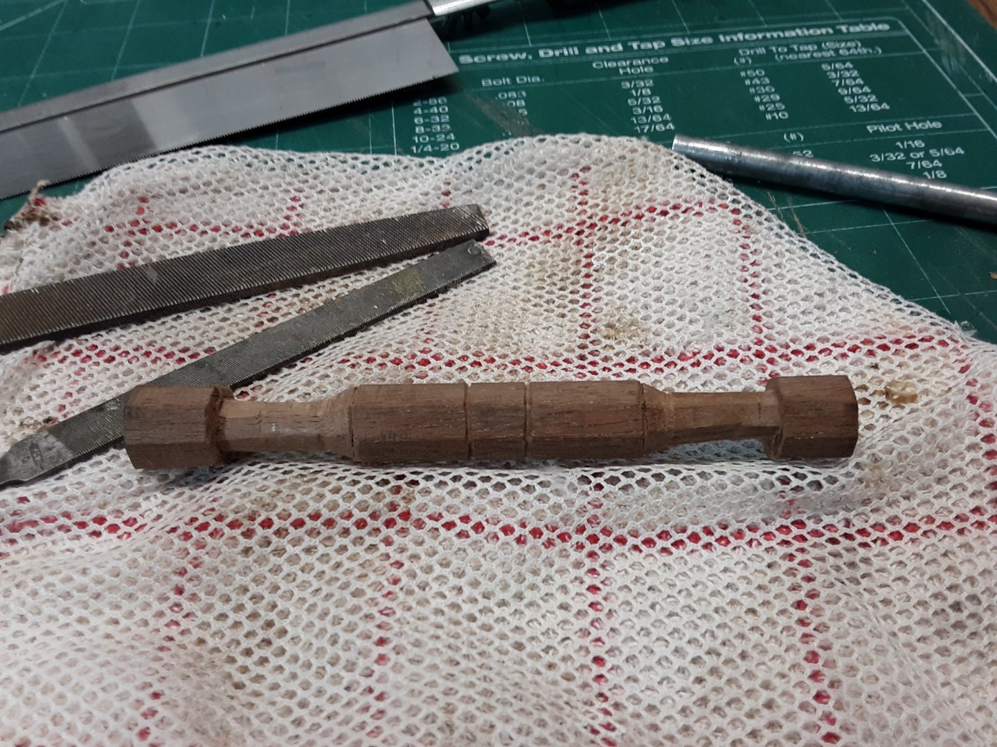
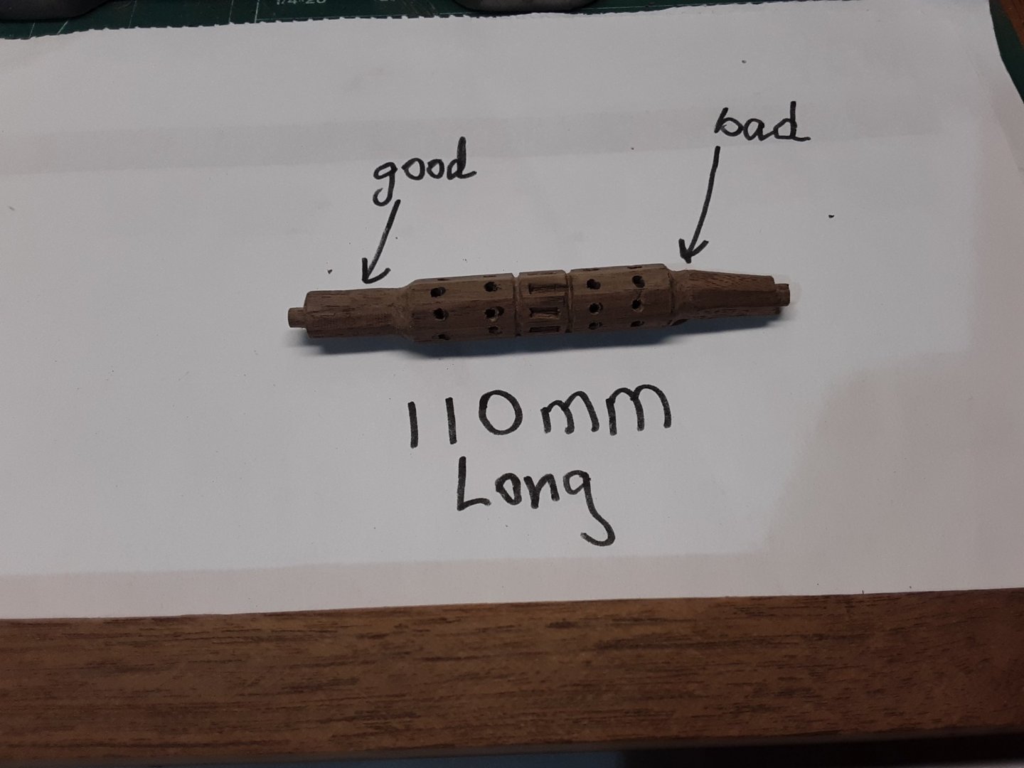
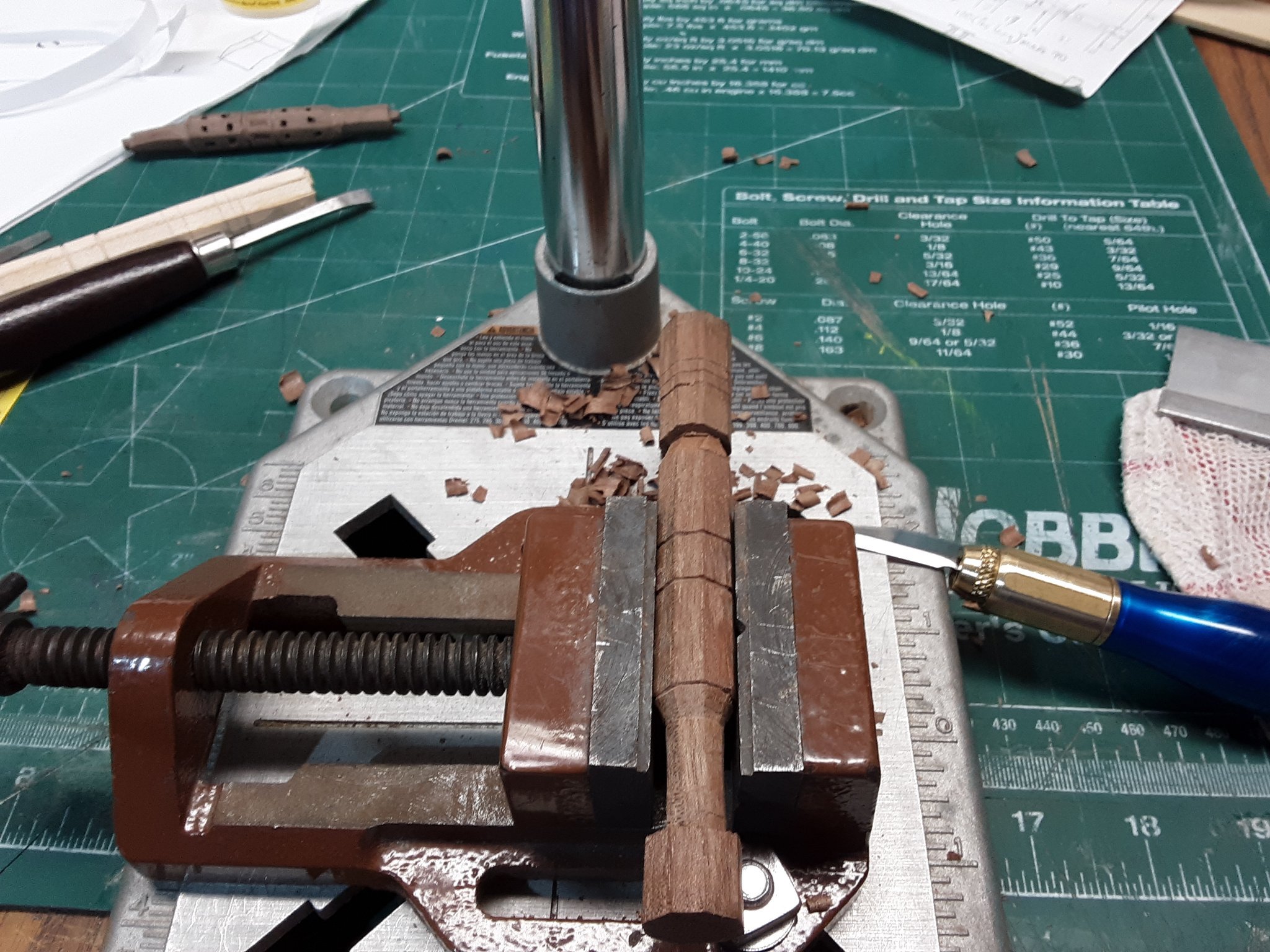
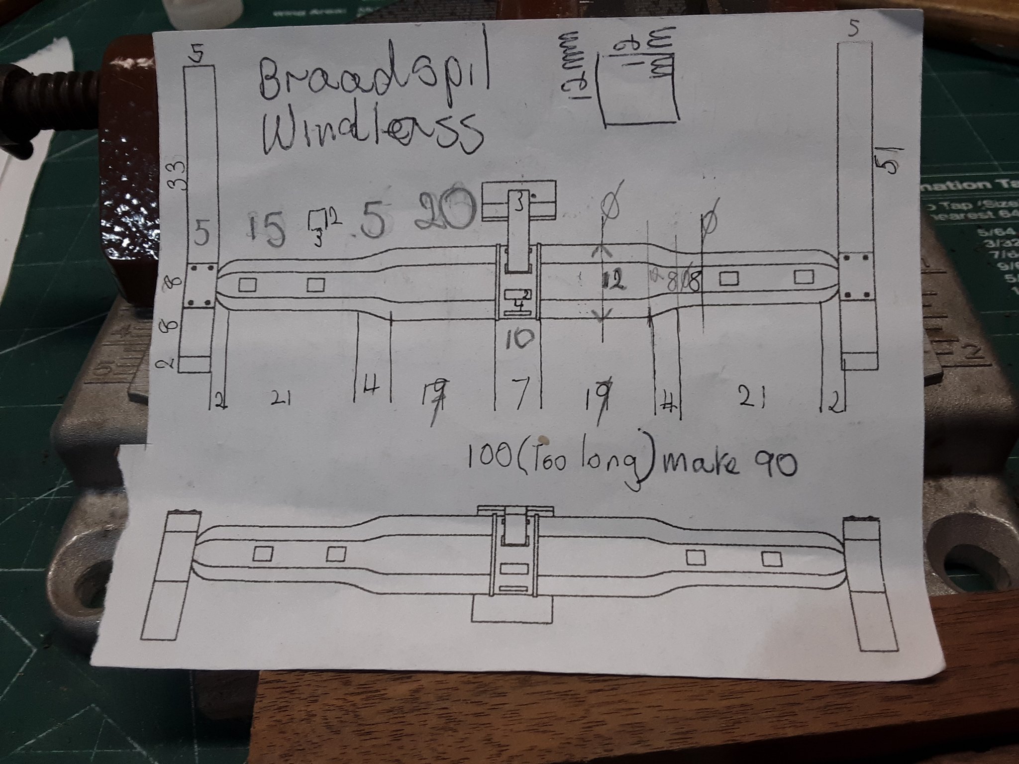
Now that there is less work in the garden I am continuing work on the Zeehaen and working on the windlass. After the 1st try, which went in the wood box the second attempt is much better. I use walnut as I have a lot of that and I like working with that wood.
This will be an 8 sided windlass. After I pm'd Ab Hoving on this he msgd., me that the Dutch in the 17th century used either a 6 or an 8 sided windlass. It all depended on how large the ship was and how much power you needed to haul material.
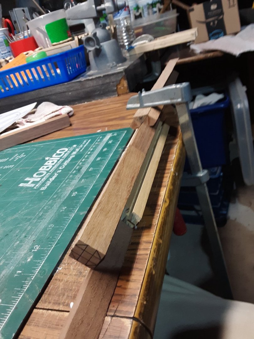
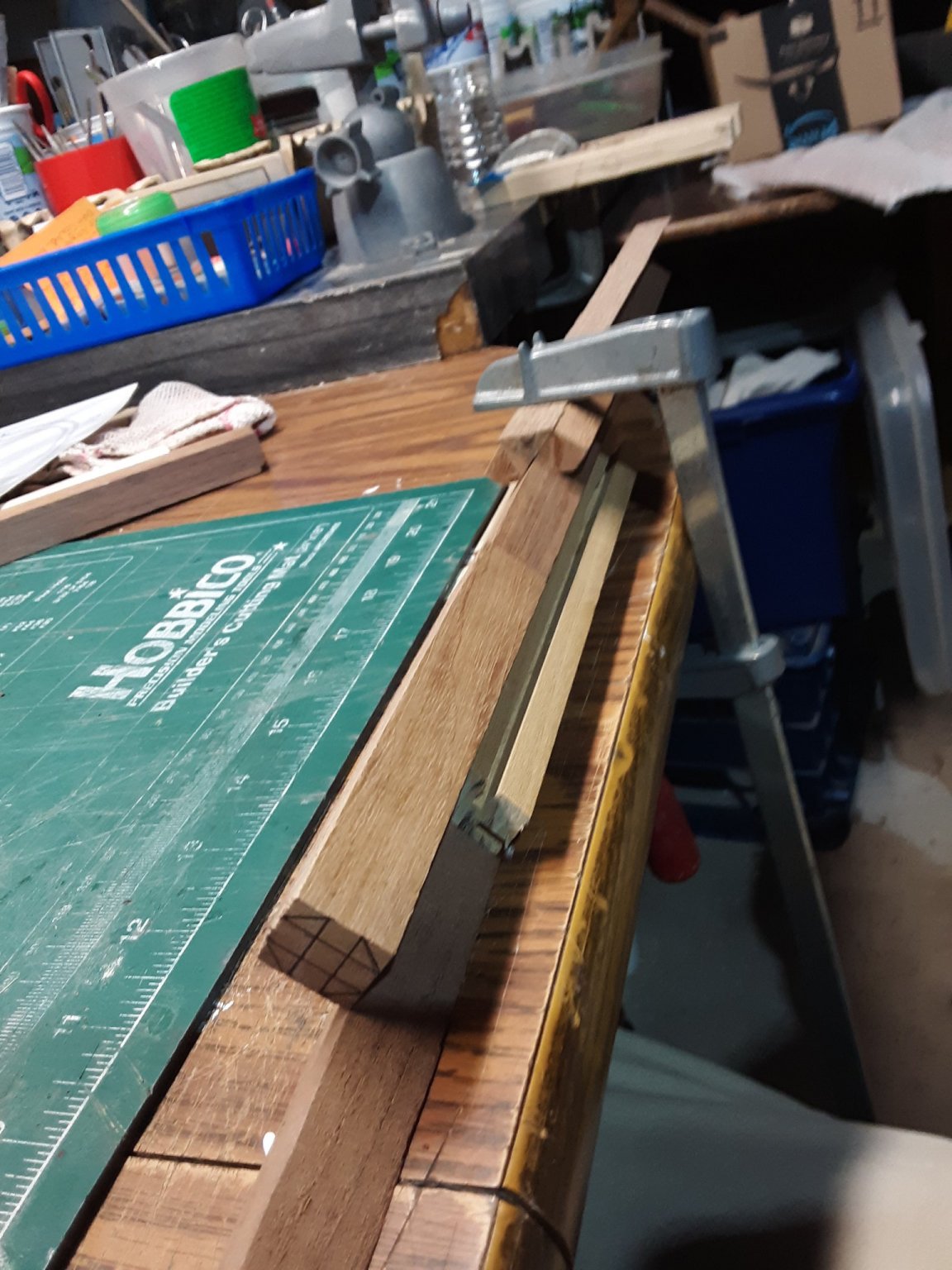
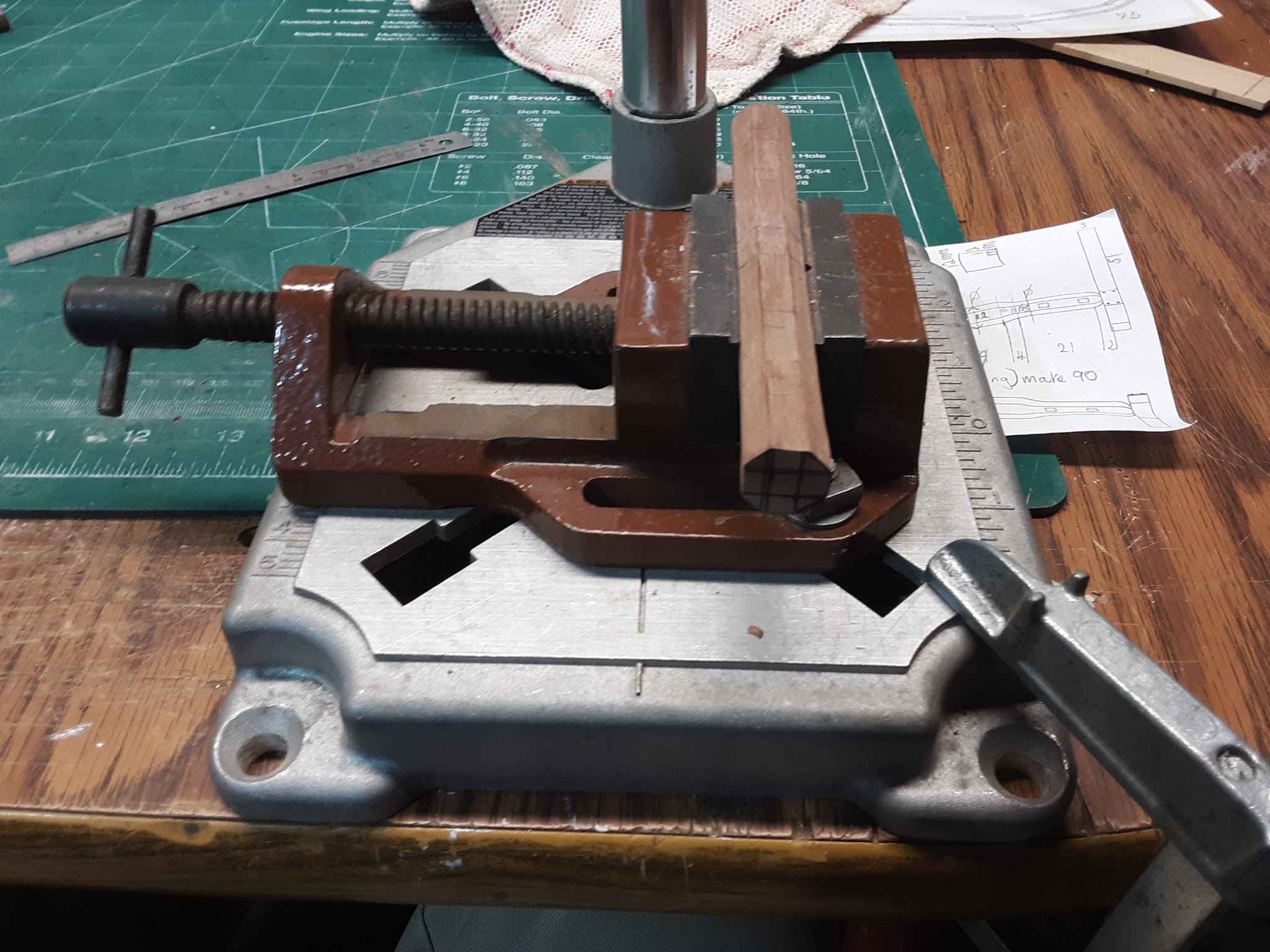
I have a jig to plane 4 sides to a 45 degree angle.

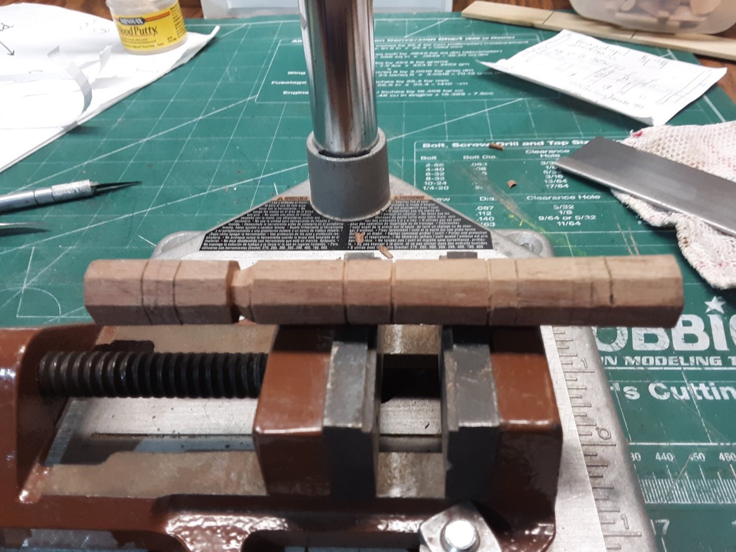
Small vice bolted to a dremel stand clamped to a table.
Mark distance with pencil and use a carving knife and Xacto blade to slowly shave of areas. The outer sides are lower than the inner ones.

Next side.
The end pieces will be cut off.
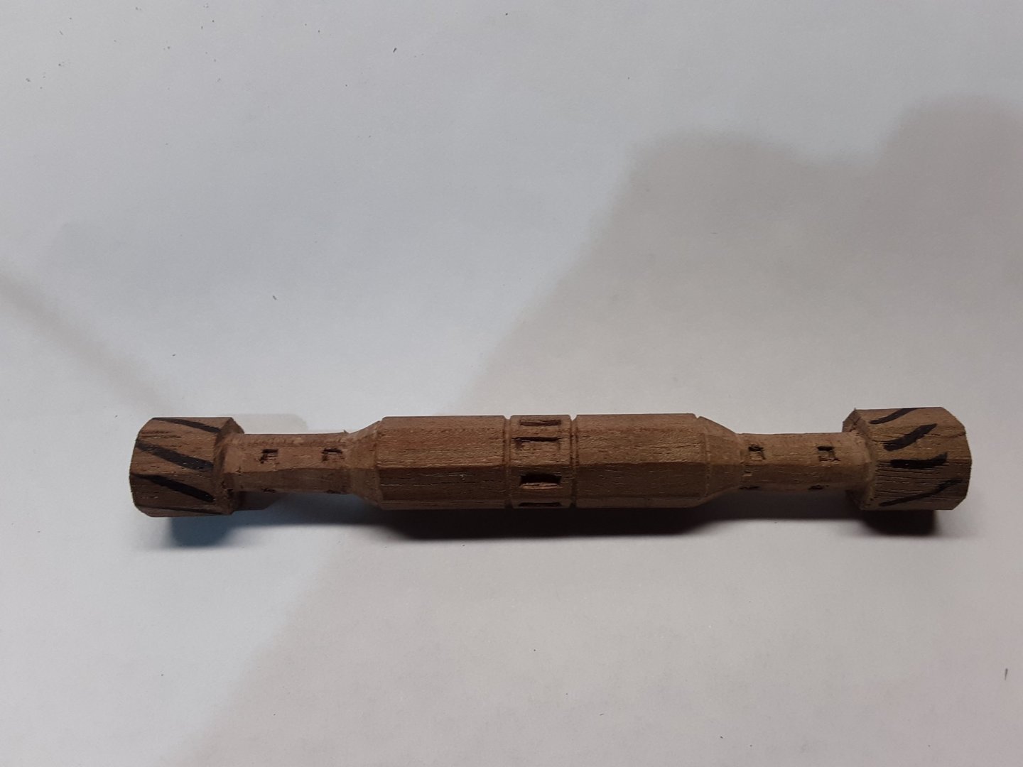
The square holes are made and still needs to be sanded.
Marcus
-
Ab Hoving replied
He thinks either 6 or 8 sided existed. Depending on the size of the ship and the power one needed to use it.
Free choices.
For the Dutch speakers.
(Ik denk dat beide varianten voorkwamen. Uitgaande van de grootte van het schip en de kracht die nodig was om te bedienen. Vrije keuze dus.
groet,
ab)
Marcus
-
Hi Jan,
Thanks for clearing that up. I looked at all the plans which are all 2D and all the books I have and I can't tell if it 6 or 8 sided. I am just assuming it is 8 sided. I found a picture on another site from a Fluit and he has it 8 sided.
From a professional model maker
I'll pm Ab Hoving here on MSW and see what his opinion is. He is the expert on 17 century Dutch ships.
Hi Steven,
Scale of the Zeehaen is 1: 37.5, so it is 110mm. The plan is 1: 75 and I doubled it all to get a bigger model with more details. Just don't know where to put it once finished. Oh well.
Sharp tools is what I use as well, vice for stabilization, glove depending on what I cut.
Marcus
-
The drawing shows it is 8 sided. Wierd looking 8 sided so I'm doing a regular 8 sided.
I am working on two attempts, one is where I will do it in 3 pieces and gluing them together and one is doing it in one piece, again.

Using a little vice bolted to a Dremel drill stand clamped to the table. I would not attempt holding it in my hand.

@allanyed
Allen,
Thanks for the advice on the wood, I'll remember that next time when I look in my stash.
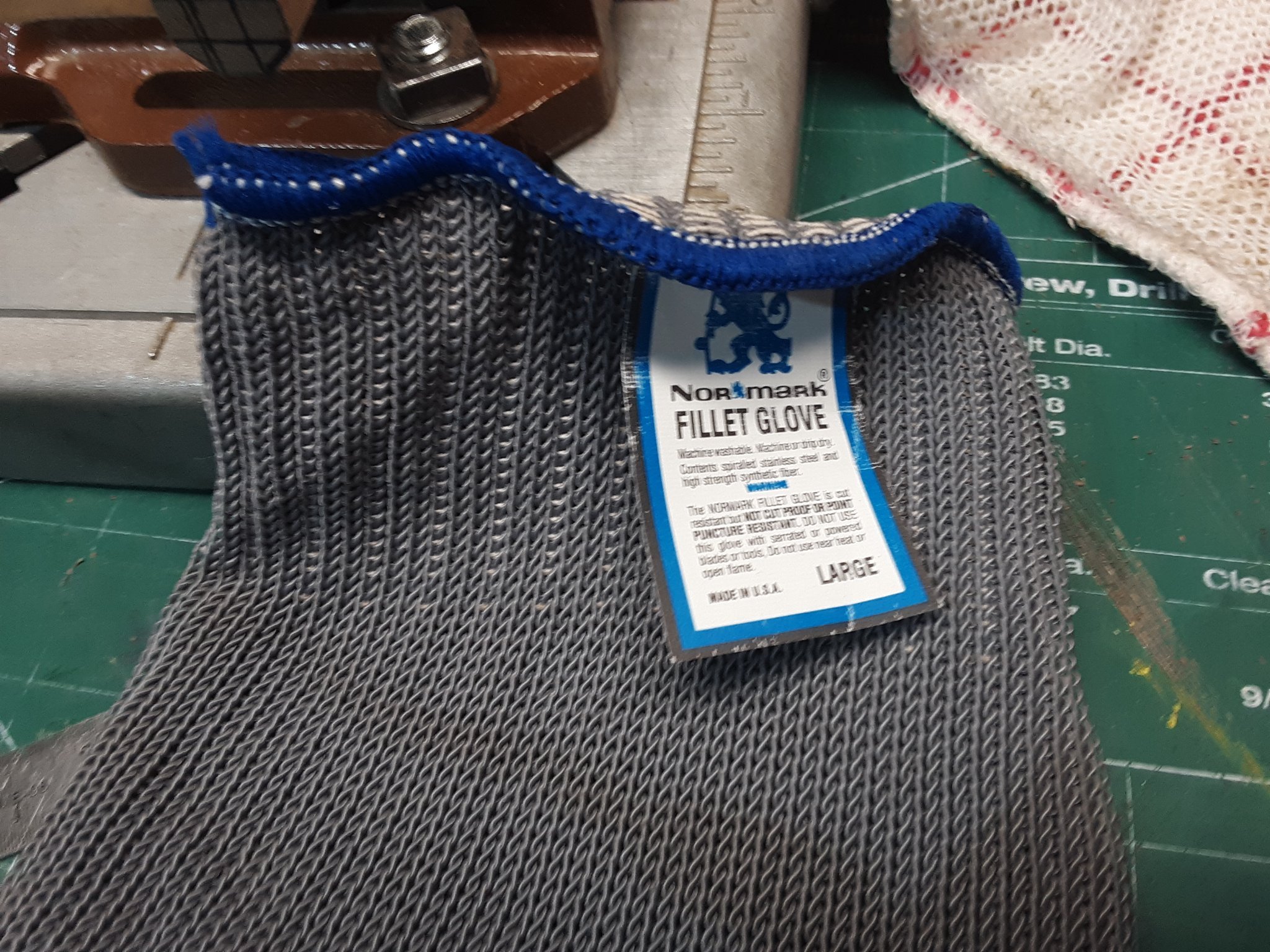
Not really Kevlar but a fillet glove.

Yes, you lose the feel of the wood and the wood slides a bit. I just wished the had little rubber grips and they may make something like it. The glove has protected my hand several times from a knife. It is cut-resistant NOT cut proof or puncture resistant.
Marcus
-
I'll take a good look at Chuck"s windlass. I like the idea that the slats with the holes are glued on. One can make them more accurate.
You should see my box of tried parts. Some items have been done several times. Practice, practice is how it gets better and that item will only have to be done once on the next ship.
You said it "thinner cuts", I need to control my movements better. I'm using the softer parts of the walnut. Sharp tools is what I use and wearing kevlar gloves so my fingers are protected.
Marcus
-
Hi,
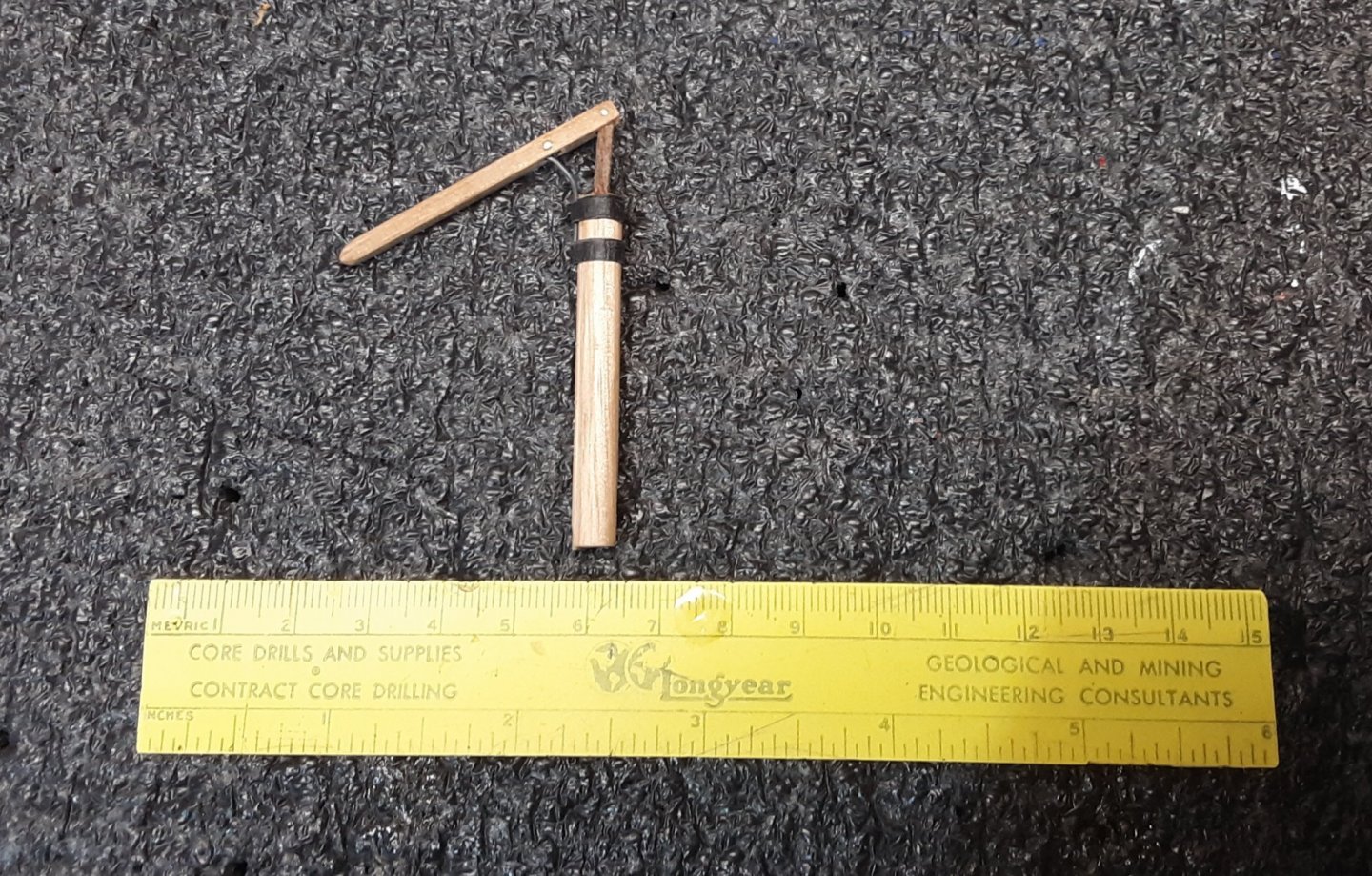
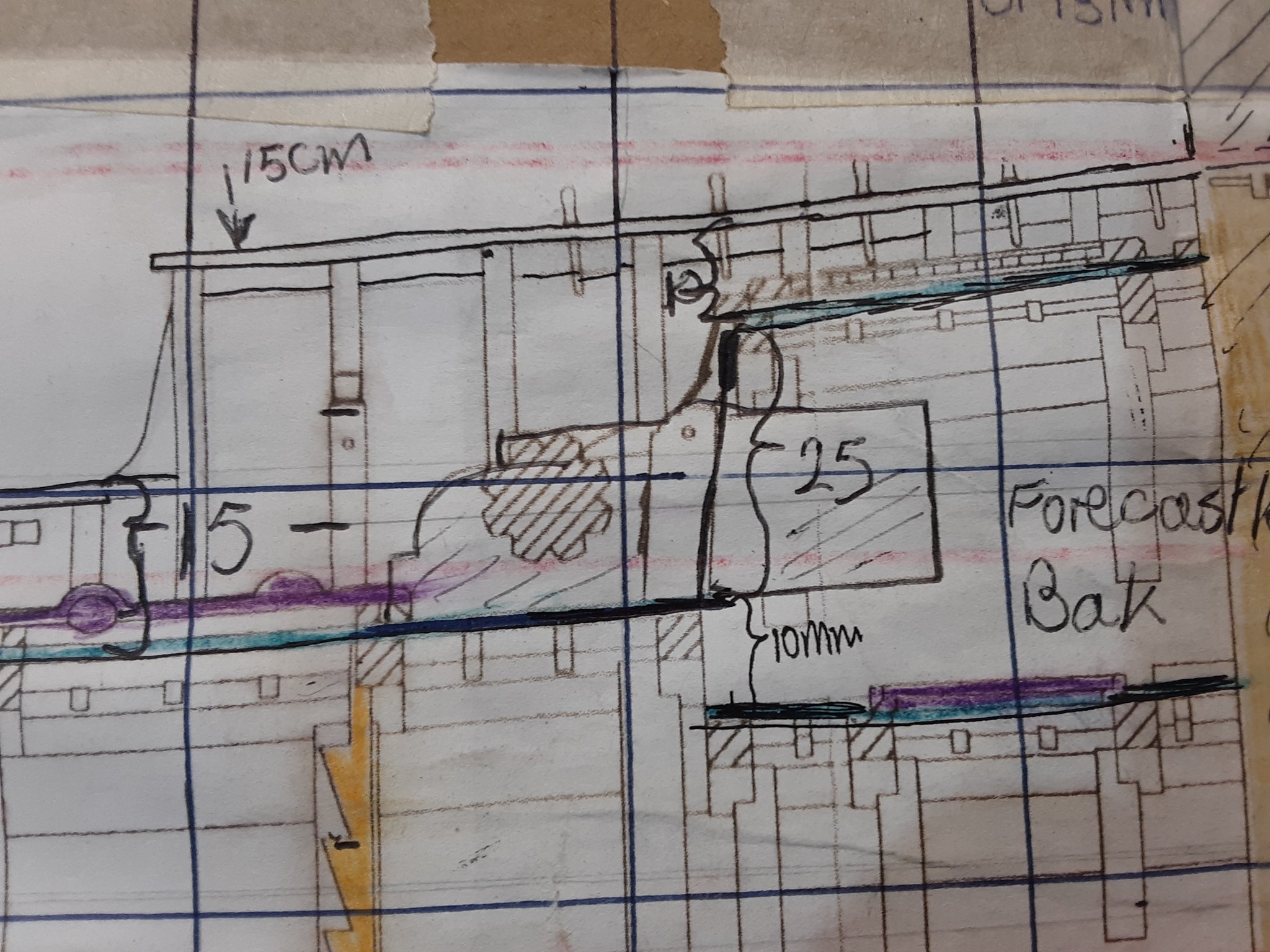
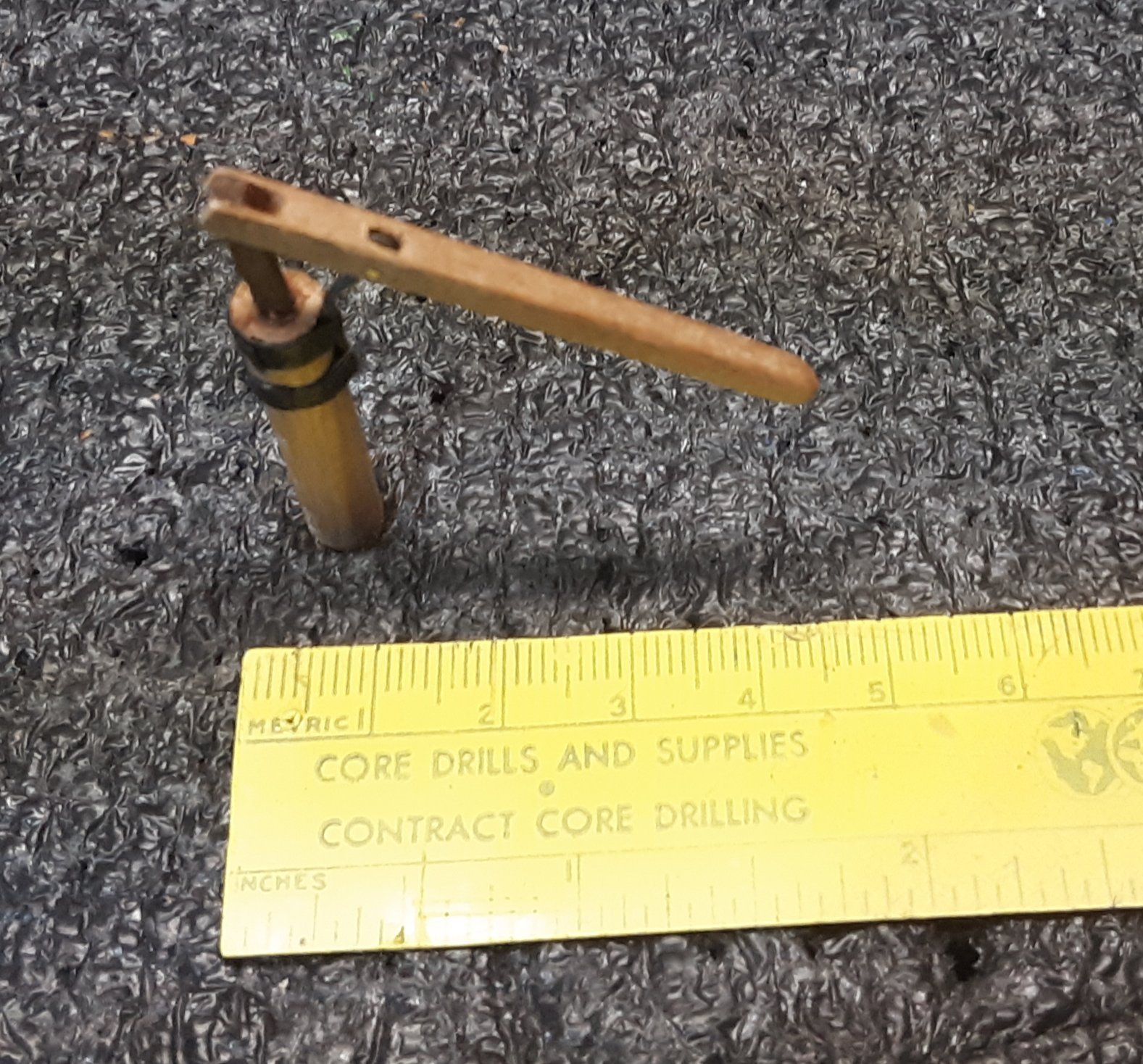
I am attempting to make the windlass for my Fluit, Zeehaen 1639. I made one but it is off on one side, so I want to make a new one. I make them by hand using a small planer, carving tools, knives, files, home made punches and sand paper.
The first one is from walnut and want to stick with that wood as I have a lot of that and easy to cut.
The easy part is making 8 sides with a plane and then it becomes a challenge.
1st attempt
Original plan (sorry about the measurement scribbles)
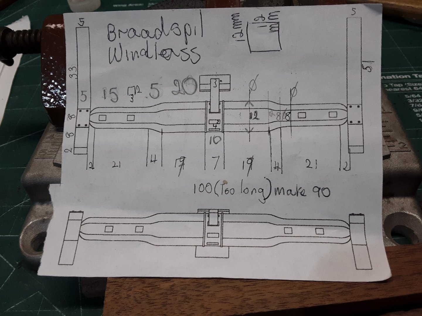
Question.
Is it better to make separate segments and then glue them together or one piece ?
Has someone else done this by hand and are there any other posts on MSW about this?
All advise is appreciated.
Thanks,
Marcus
-
I was revisiting some of my old builts and I see there are questions.
What I liked so much about Bluejacket Shipcrafters models is that the plans are well put together. On the other hand the instructions can be better.
My sister has the model so I can't give you more pictures. I thought I had enough on this build. There are others that have built a Cape Cod catboat herre on this site so take a look at those boats and see if your questions can be answered.
Marcus
-
This is great material. Will research it further. Thanks a lot.
Marcus
-
-
Today till Saturday on and off rain so no garden work. We get much needed rain whereas the South and the East of the US are floating away as they have too much rain.
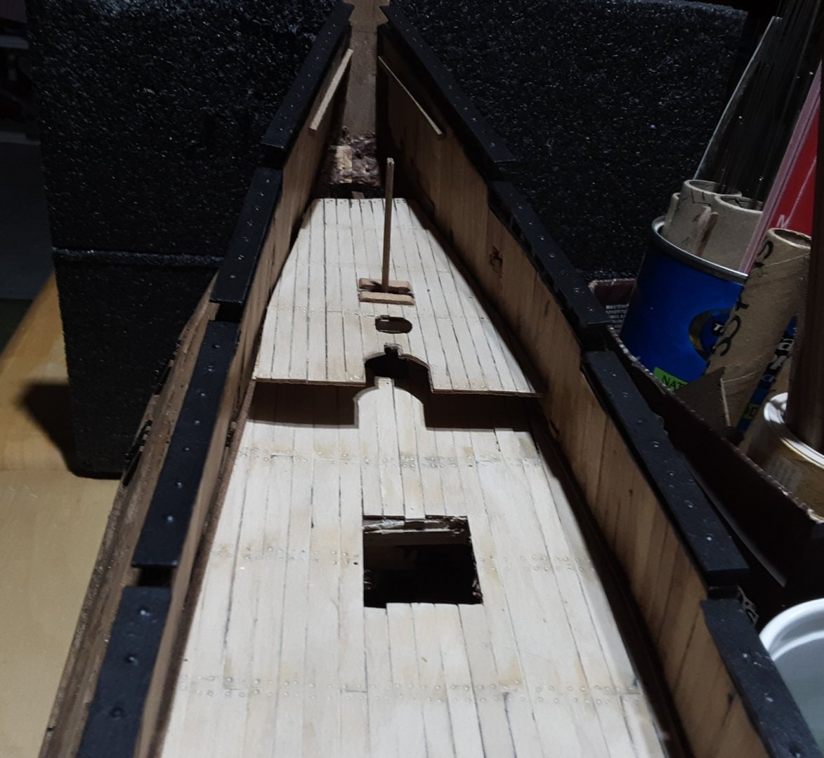
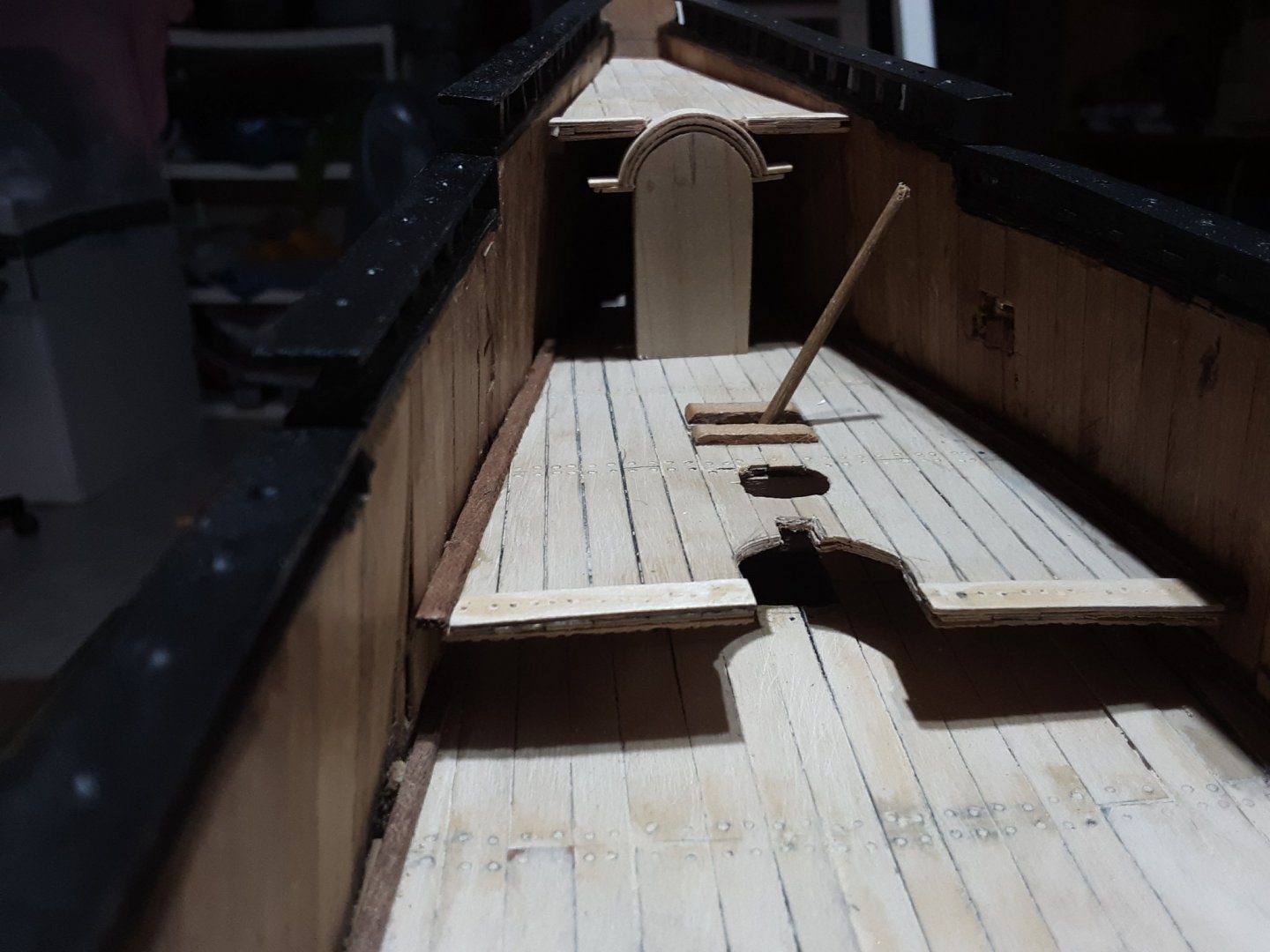
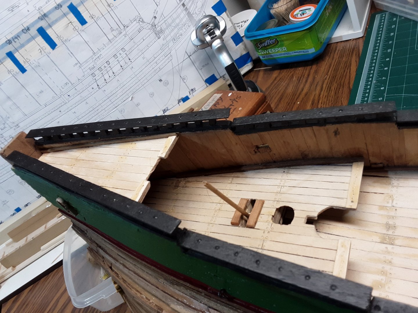
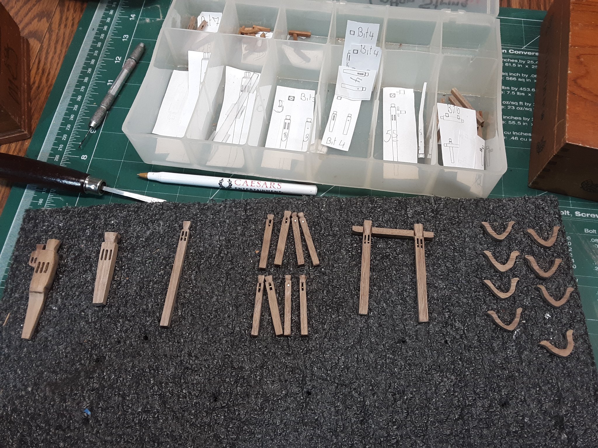
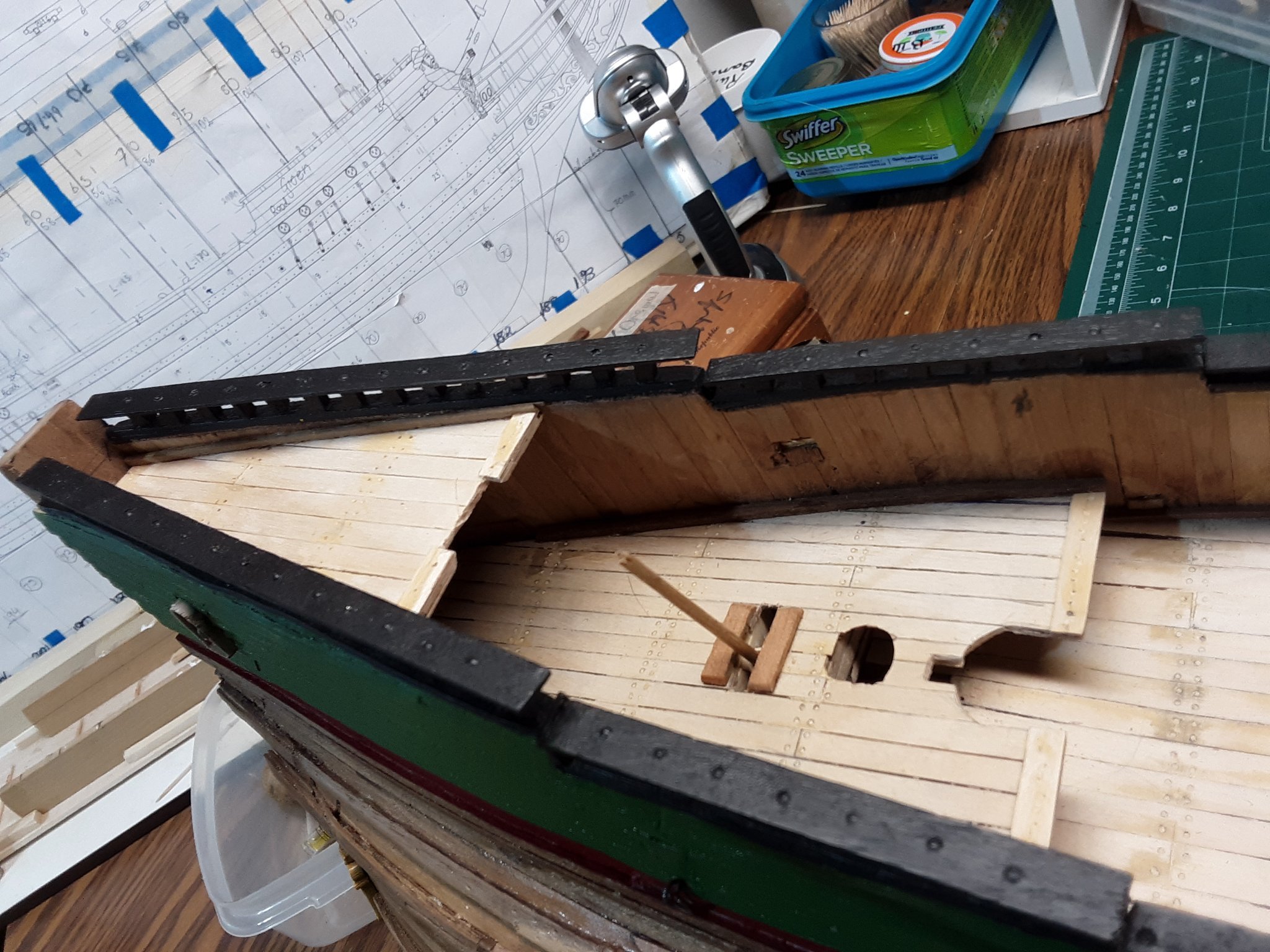
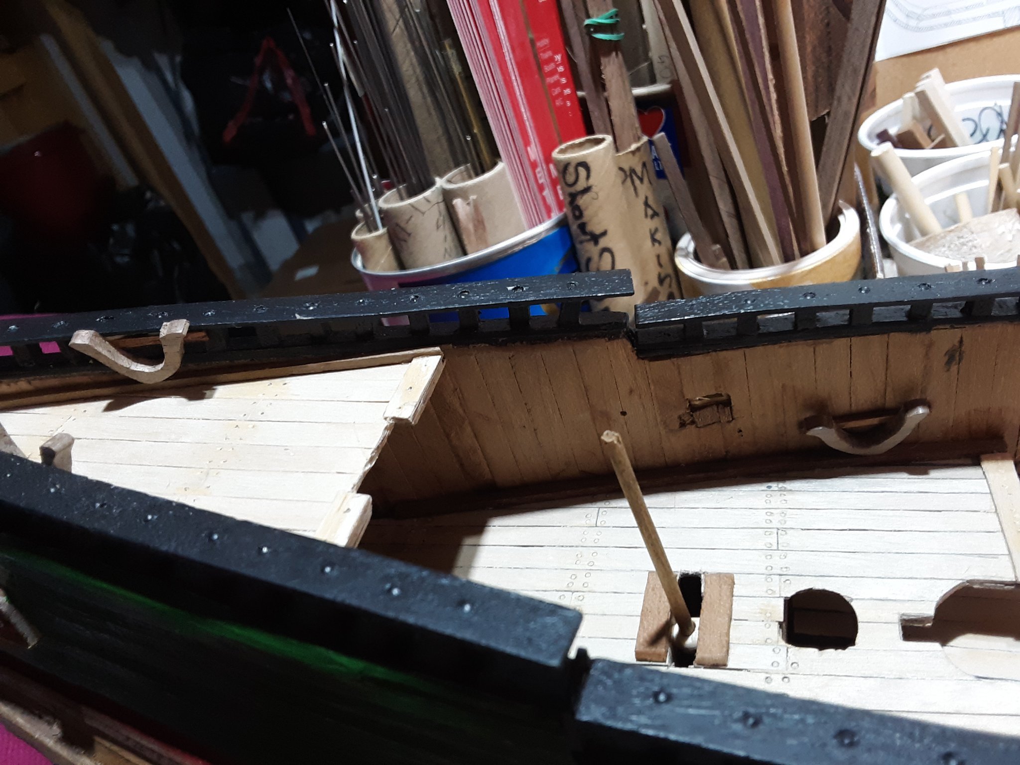
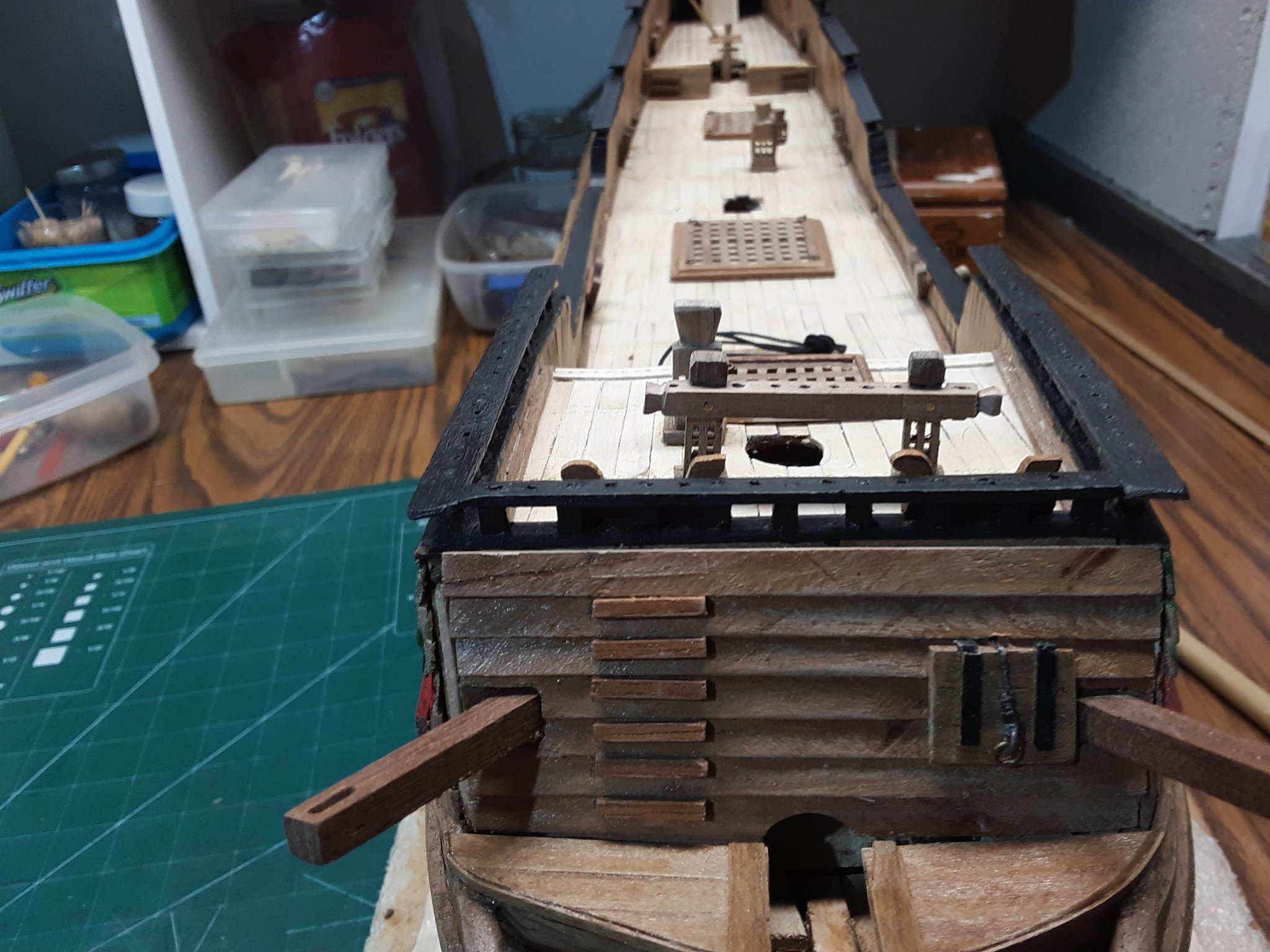
Actively working on deck items.
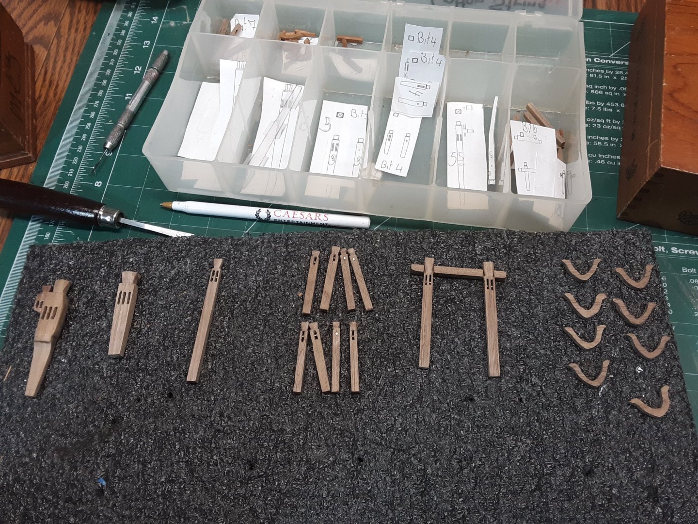
Different types of bits.
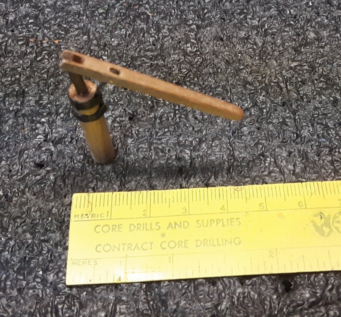
Pump
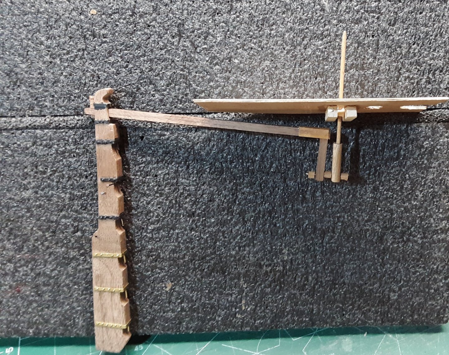
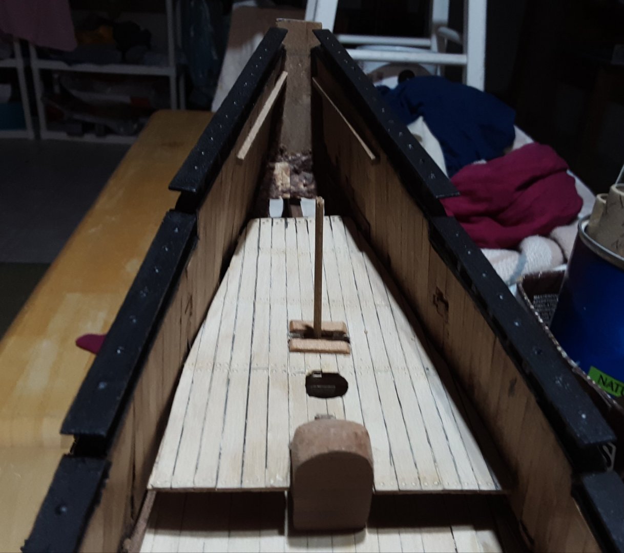
Whipstaff and how it is installed under the deck.
Whipstaff
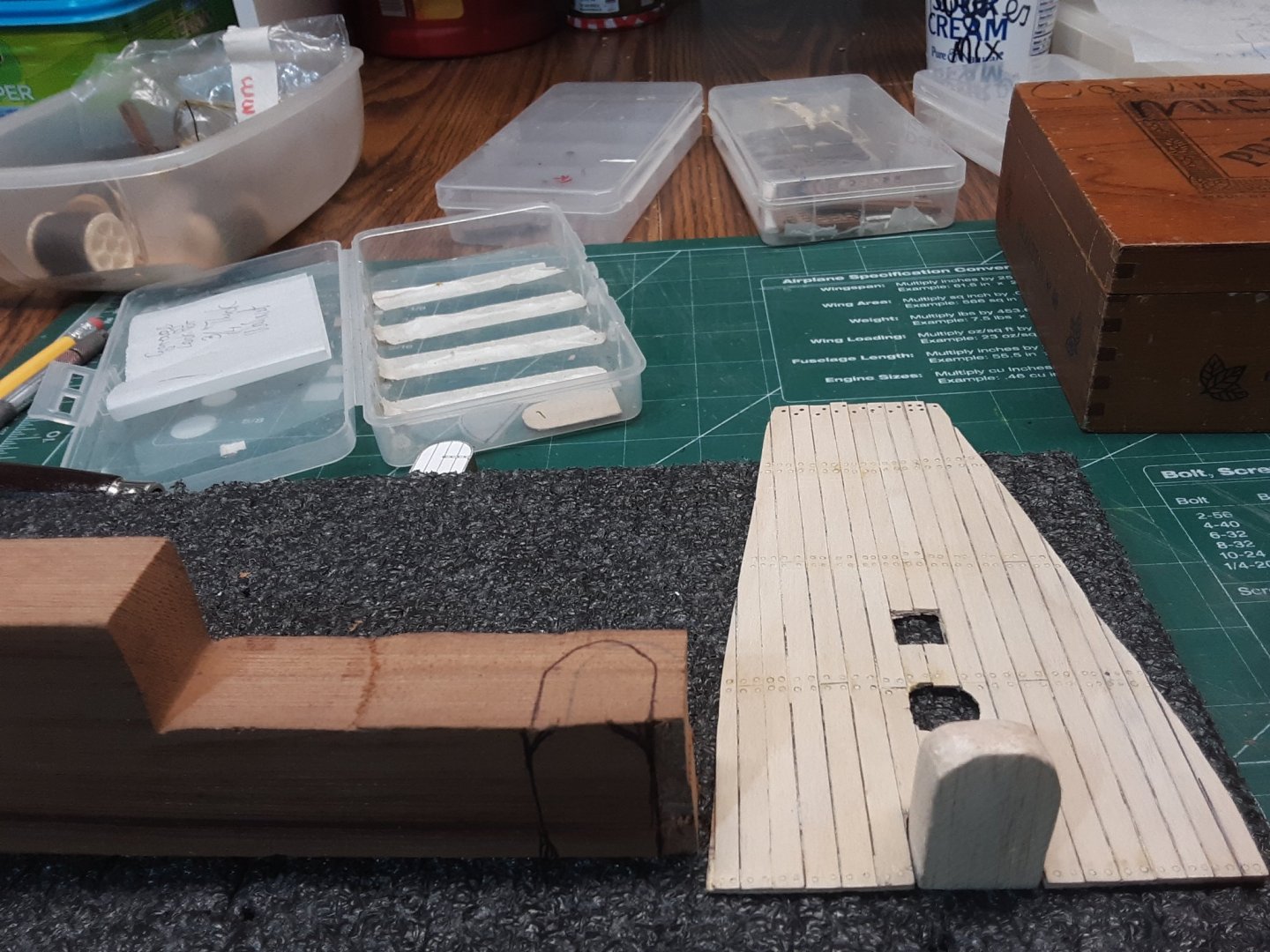
This door is first cut out of balsa and sanded to specs. On the left a block of cherry with the outline of the door
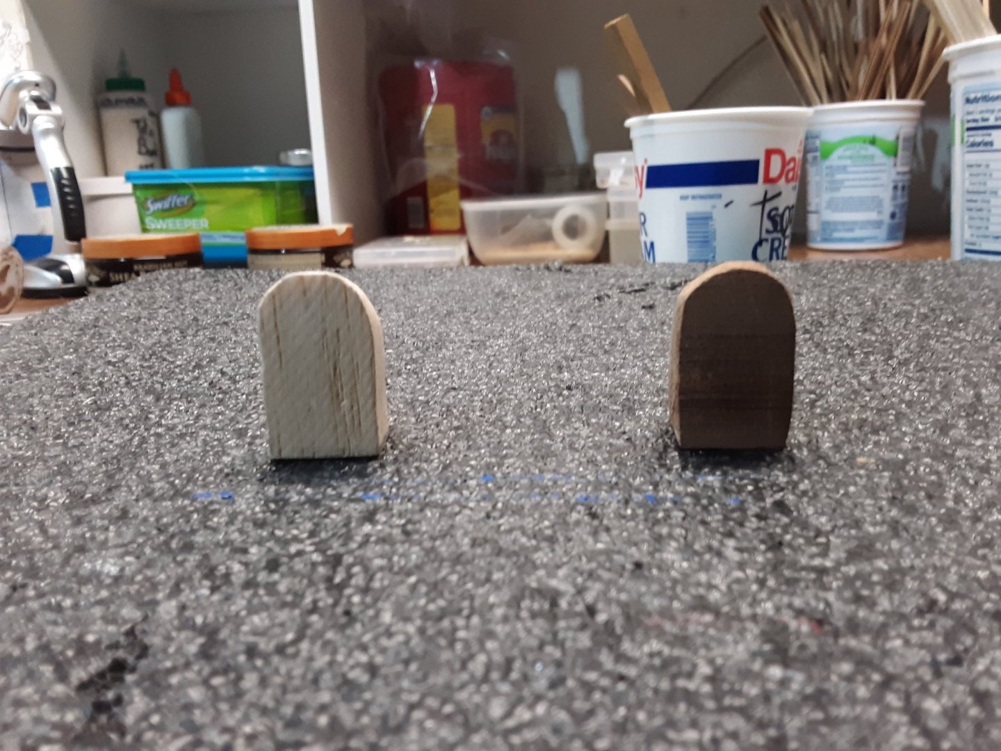
Balsa door template on the left, final cherry door on the right.
Location of the door.
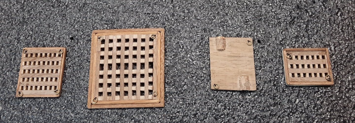
Gratings made out of cherry and walnut.
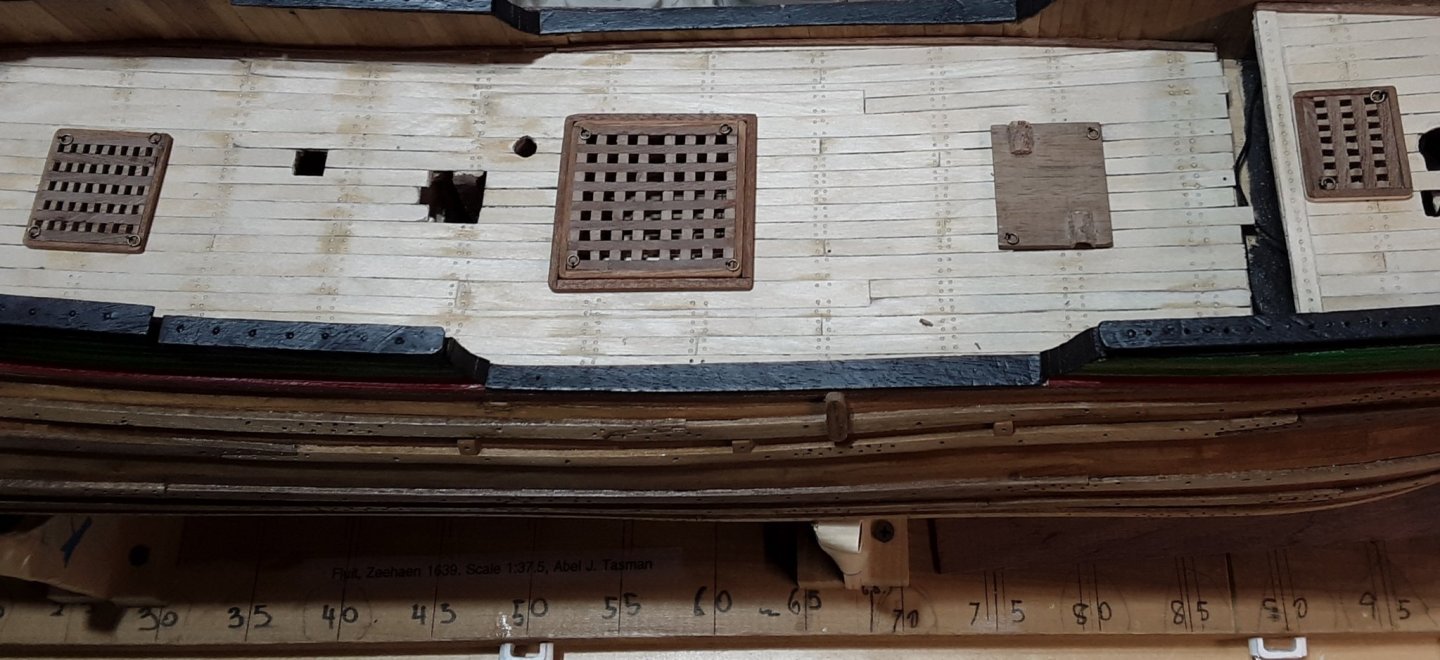
Gratings installed on the decks.
Door from the captain's quarters.
Different layers of decks.

Different installed bits
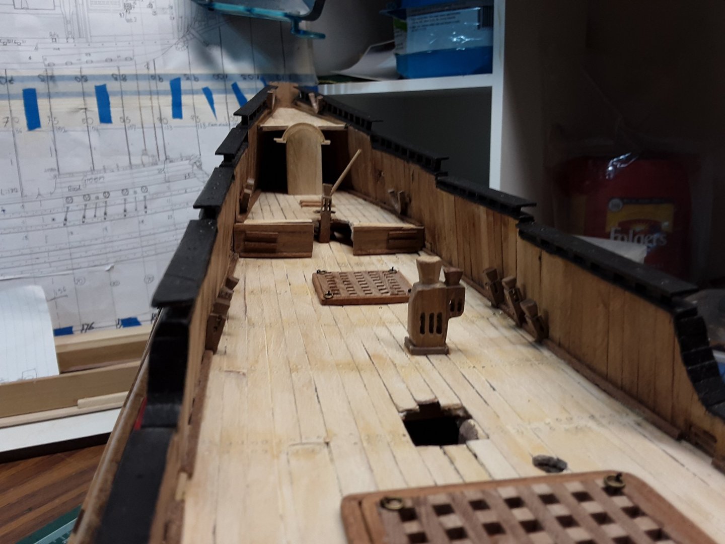
Deck items in place.
Deck items.

Marcus
- Meriadoc Brandybuck, Baker, G.L. and 5 others
-
 8
8
-
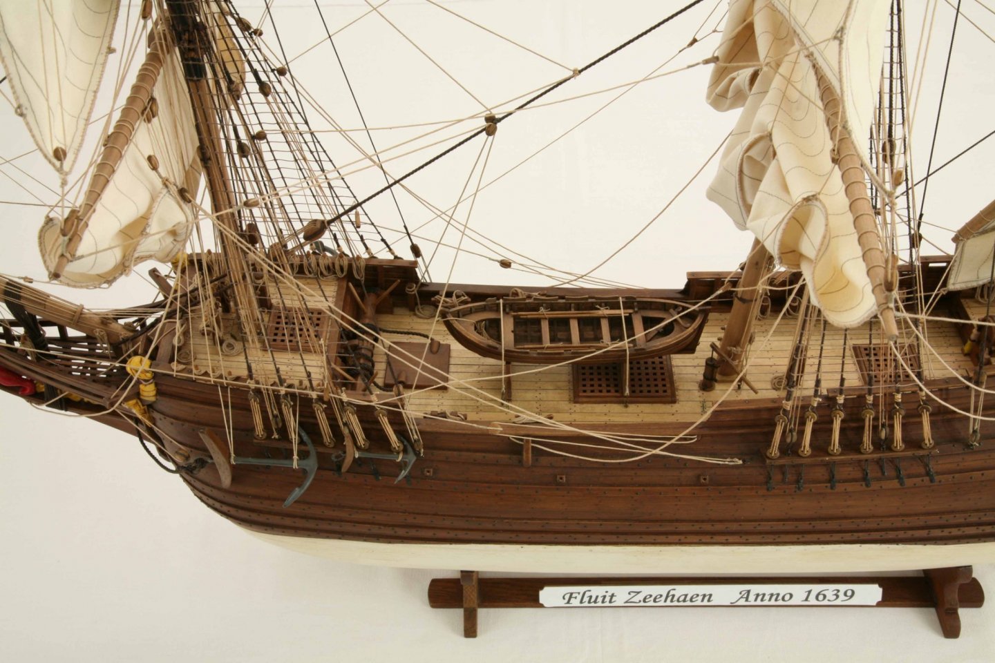
Beautifully executed. Love the nails in the hull.
Marcus
- mtaylor, thibaultron, Keith Black and 1 other
-
4
-
@allanyed, @Bob Cleek, @Bill Hudson, @reklein and @Gregory
I thank you all for the information and advice. I will definitely get a draw plate and look into model RR nails.
The long black nails I presently have so few of were used for my Marklin model RR which I purchased in the 70's and 10 years ago sold all of it on eBay to someone in China.
Marcus
-
-
Thank you for the detailed information. I will look up the name you gave me. I have not tried a draw plate and I know I should have been doing that a couple of ships back. Smallest scale I built is 1 : 48 and larger. My Fluit, the Zeehaen is 1:37.5.
The built I saw it on was from a meber by the name of Ondras.
I've seen builts where the tree nails are too large and it looks horrible.
I saw how Tosti did it with his Clipper ship and that was very cool the way he did it.
Dutch ships in the 17th century used big black nails of various sizes. Several pictures from the Statenjacht Utrecht book by Ab Hoving shows how it is done. I visit friends in Holland every 2 to 3 years and then visit several maritime museums. Many models on display have black nails. I have used this as well on the Utrecht and a small Dutch merchant ship called a Boyer. I am running out of the nails an I've been researching an alternative. In the US they are called "bank pins".
I will try the draw plate and bamboo.
Marcus
-
I saw on a built little wooden pegs created by a hollow 0.65mm needle to be used on the hull of a ship.
Where can I get something like that and are there other diameters?
Thank you in advance.
Marcus
-
-
@Bob Cleek, @allanyed and @DelF
Thank you all for de detailed information and I downloaded the spreadsheet from Danny Vadas.
Also downloaded the spreadsheet from the Schooner thread from Dr. P.
Furthermore, because I only build Dutch merchant ships from the 17th century I asked the same question on a Dutch model site (www.modelbouwforum.nl). They refered me to books written by Ab Hoving, a member here, and an expert on Dutch ships. I have all his books
I am going to compare the British ship measurements to the Dutch ship measurements and see how much difference there is.
Thanks again.
Marcus
-
What are the rules for determining the thickness of rope for standing and running rigging and what formulas do you use to get to the dimensions?
Especially large ships such as man-of-war, Pinas, East Indiaman, etc.
When I scratch built the Utrecht, the Boyer and other smaller Dutch ships, I guessed the rigging and the results were good. Now I am building a larger ship en cannot guess the rigging anymore.
Books I have:
C. G. Davis, The Ship model builder's assistant
G. Biddlecombe, The art of rigging (pretty good explanations lots of tables but not how they got the numbers)
R. C. Anderson, The rigging of ships in the days of the spritsail Topmast 1600-1720
W. zu Mondfeld, Historic ship models (reasonable explanation)
M. Roth, Ship Modeling from stem to stern (very extensive explanations)
D.Steel The Art of Rigging (1796)
- Are there other books, Excel spreadsheets, and URLs where the given question is discussed?
- What are the math formulas with answers?
- Can someone give me and write down an example?
- How Do I read figures in tables?
For example in Montfeld's book on page 308 and 309, Running rigging sizes.
Mainmast, Main Course, Tye for 16th/17th century it is 50%.
-50% of what?
- Where did this number come from?
- What is the formula used?
Then on page 308 (Montfeld), in the lower left corner there are a few sentences explaining that the figures refer to the thickness of the main stay, 0.166% of the diameter of the mainmast at the deck (100%)
Again, how do I read this?
It is confusing.
Thank you in advance for answering my questions
Marcus


Where can I find metal wire?
in Metal Work, Soldering and Metal Fittings
Posted
Hi,
Where can I get metal wire and it cannot be shiny?
I am running out of my different types of wire. Such as 18, 20, 22, 24, 26 gauge steel wire.
I use it mainly around my deadeyes, chain plates, preventer and some other uses.
It needs to be easy to be d into shape and avain I hate shiny material.
Any recommended websites or stores?
Thank you in advance.
Marcus