


JpR62
-
Posts
697 -
Joined
-
Last visited
Content Type
Profiles
Forums
Gallery
Events
Posts posted by JpR62
-
-
Before installing the hawse plates, I glued the front part of the cap rail.
I cut it out of a 1/16" sheet of Alaskan Yellow Cedar with a cutter (I don't have a scroll saw at the moment and boxwood of this thickness is really too hard for a cutter). Alaskan Yellow Cedar is ideal for this job and since the cap rail will be painted black, the wood species used is of little importance.

The cap rail has been intentionally cut out leaving a margin on each side. It is then sanded to the correct width after gluing to the model. Protective tape was applied to the inner bulwarks to protect the red paint as much as possible.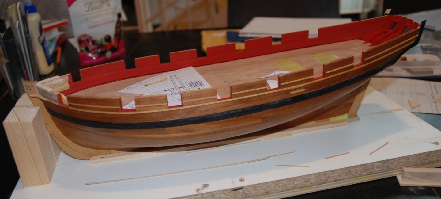

-
The small "ear" was cut out of a sheet of boxwood. I first cut its shape out of a sheet of cardboard and after several adjustments I was able to use this template to reproduce its shape on the boxwood.
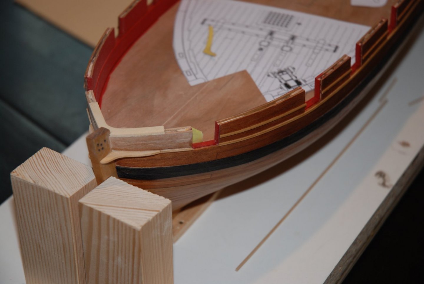
The last segment of molding was glued on after the 'ear' was in place.- bruce d, FriedClams, Ryland Craze and 4 others
-
 7
7
-
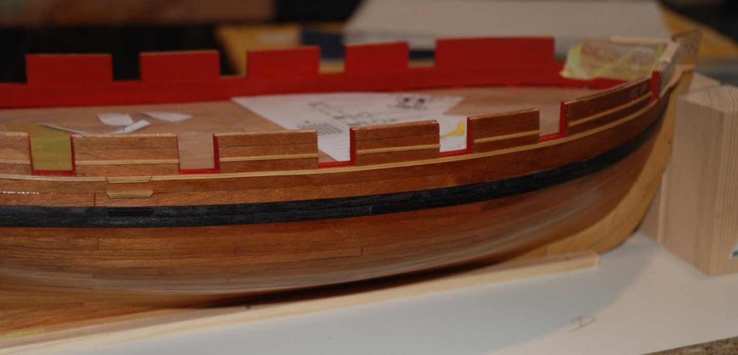
The fancy moldings were made using the scraping technique.

I used 2 different profiles and the 1/16" x 1/32" boxwood strips were then shaped by making many light passes across the strips.
-
Thanks guys for your kind comments and Thank you for all the 'Likes'
I started by working on the boarding ladder. It seemed like a better idea to do this task before I put the molding in place because it saved me from having to cut and peel the molding segment at the ladder location afterwards (thanks to Stuntflyer for bringing this to my attention in his excellent build log).
The boarding ladder steps were constructed from a 3/32" x 3/32" boxwood strip.I used my proxxon MF70 micro milling machine for this. Once the different levels were milled, they were rounded with emery paper.
For a precise cutting of the angles a small jig was built in order to be able to reproduce regularly the angles. Once the steps were cut, I used a needle point and the blade of my cutter to continue the profile on each side.
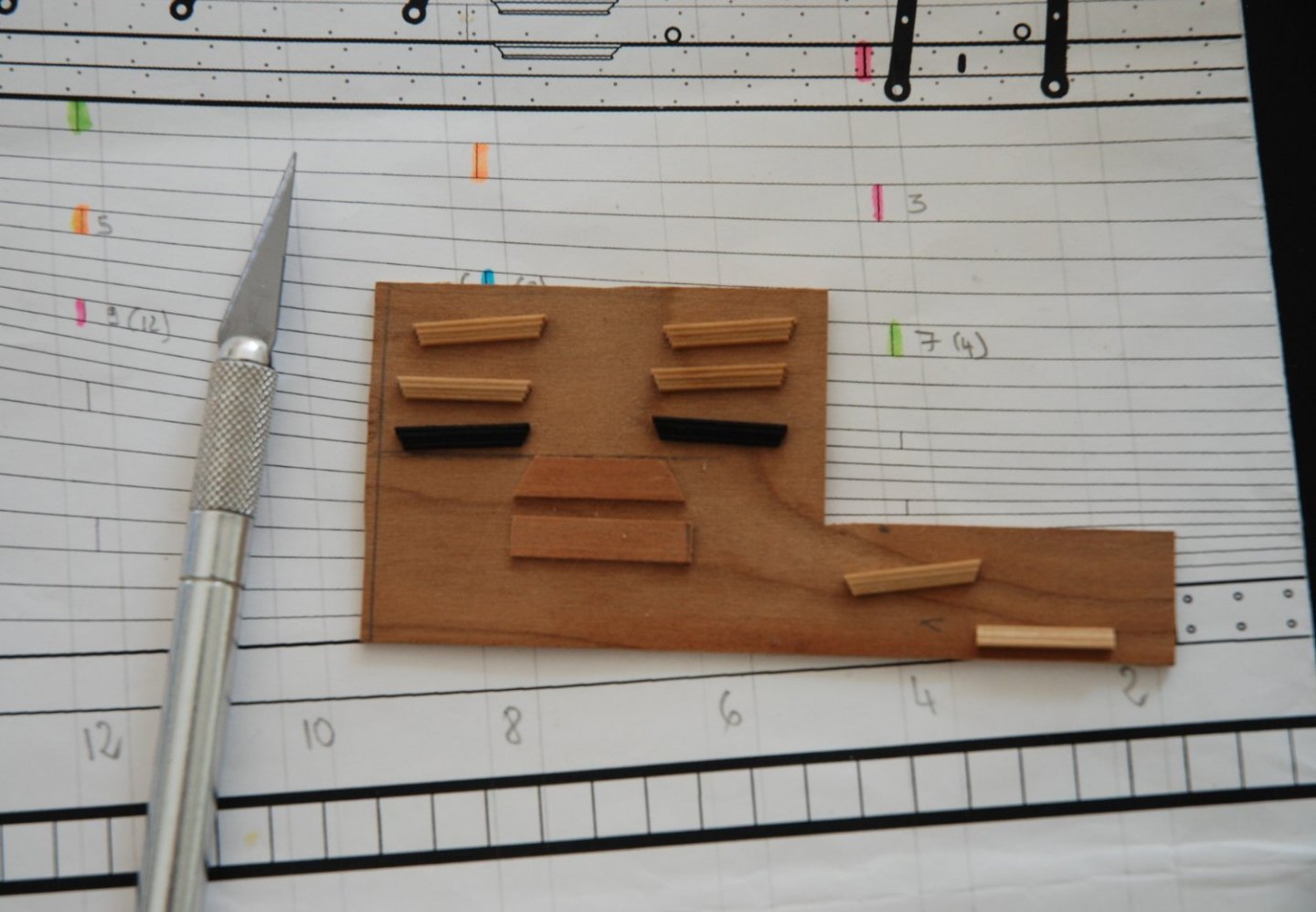
The bottom step is painted black since it will be positioned on the wales.
Next step is the moldings.- BobG, Ryland Craze, GrandpaPhil and 4 others
-
7
-
What a beautiful deck, Jason. It's really a fantastic job.
-
-
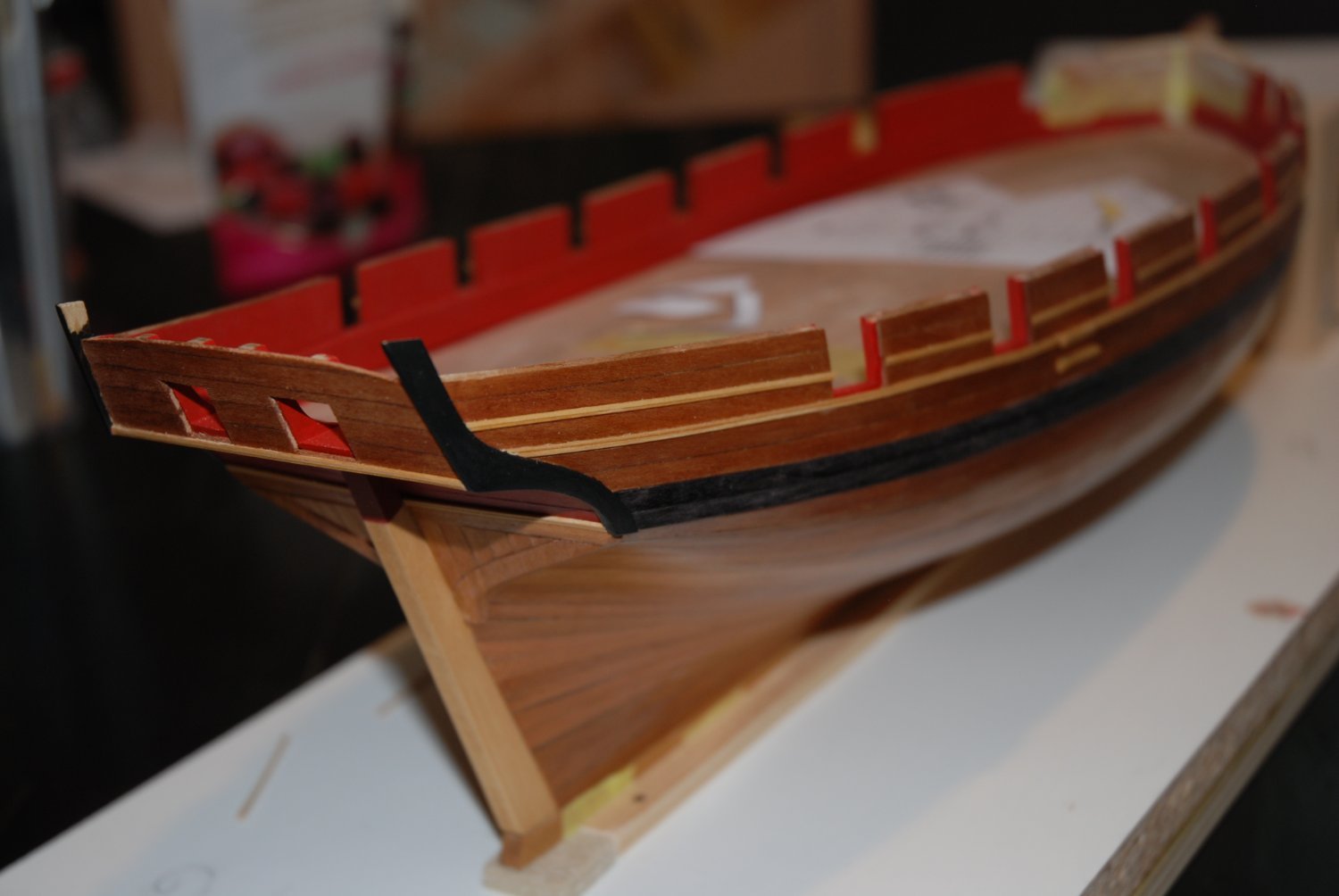
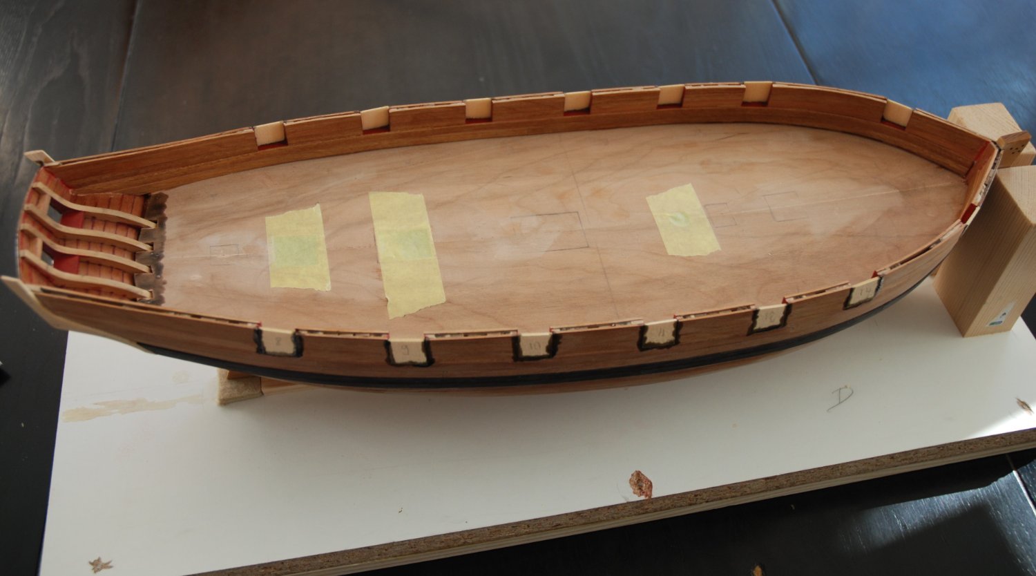
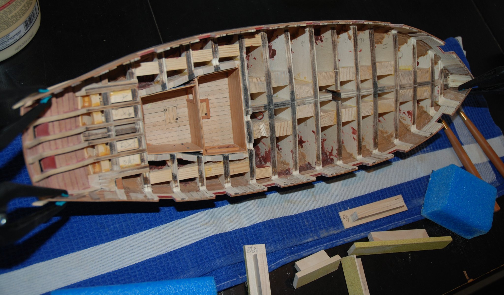
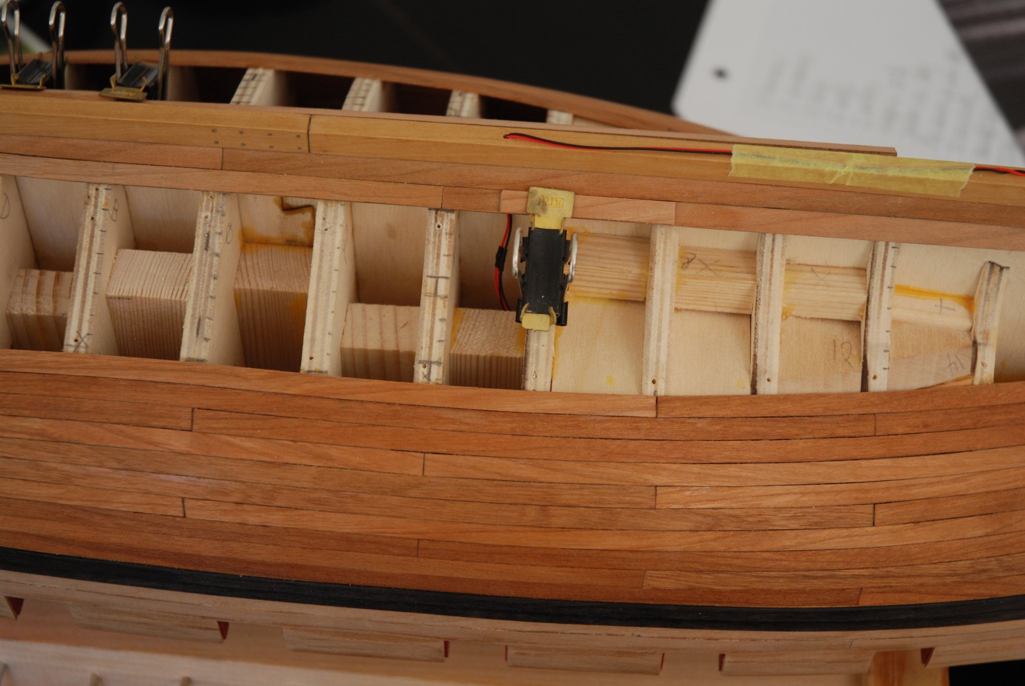
Over the past few days, I have been finalizing the internal planking.
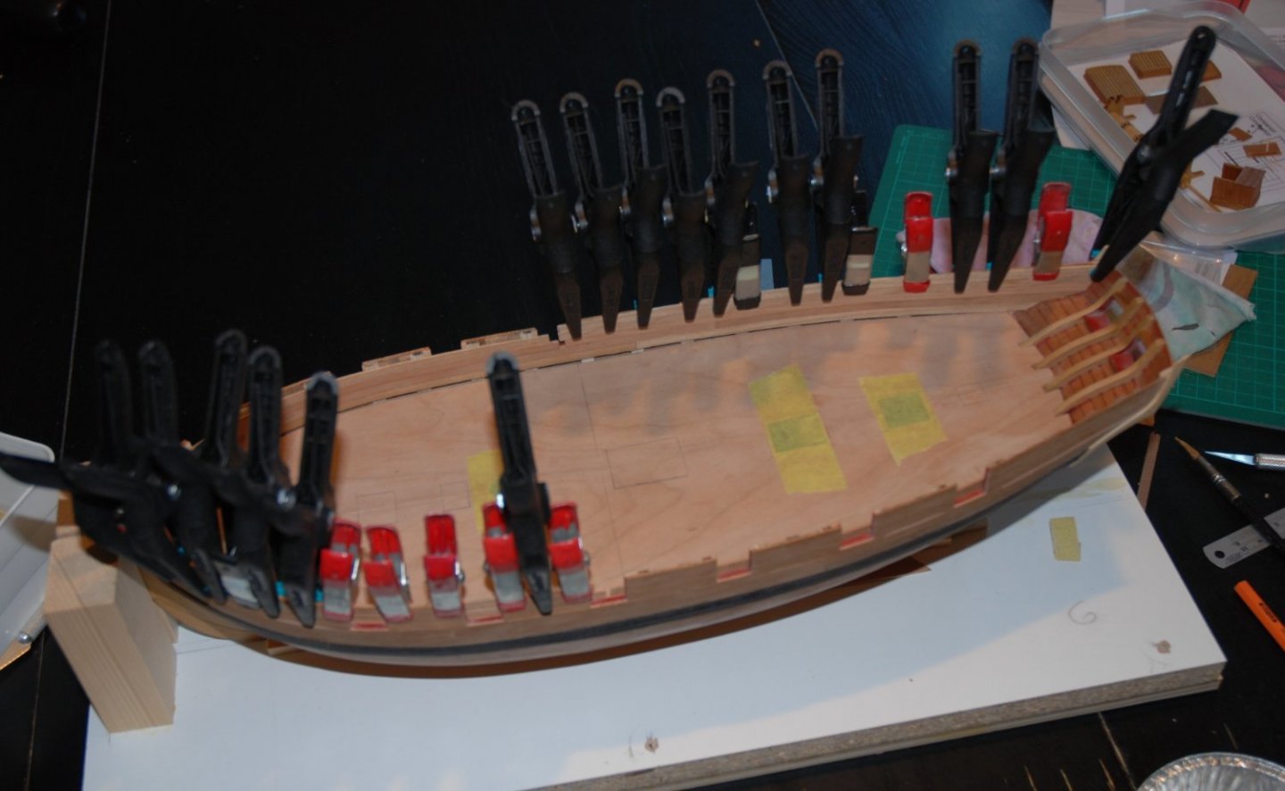
I first applied the first layer of planks having decided not to cut them between the gun ports in order to obtain a very regular curvature.
The gun ports are then opened with a cutter and sanded. I had to add some wood filler on the 2 bottom rows because I must have been a bit heavy handed when sanding the bulwarks. It doesn't matter because a second layer of planking will cover them.
The second layer of planking was added below the ports in order to simulate the spirketing.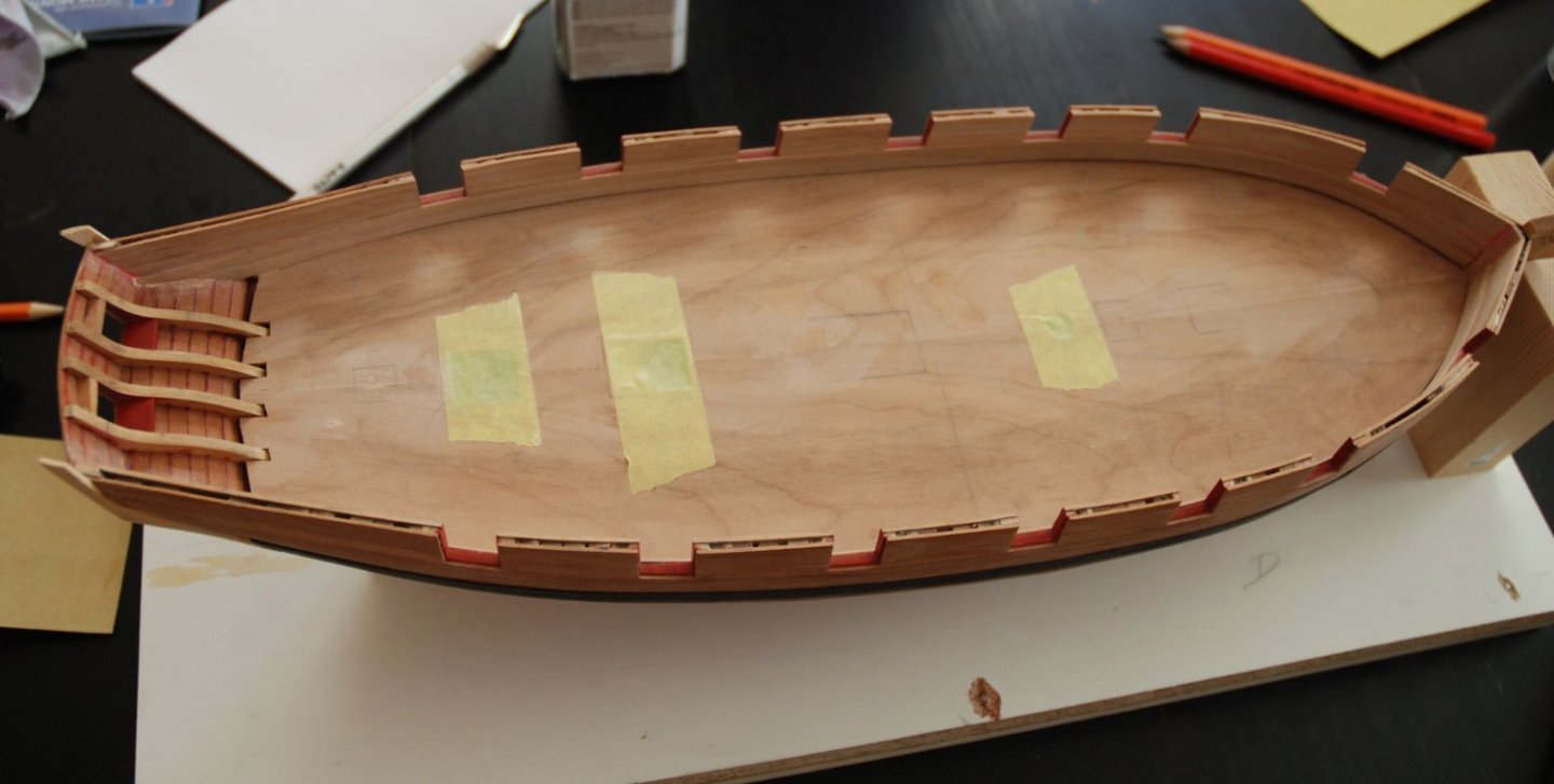
The whole is sanded to prepare the coloring that will be applied first with an airbrush.
The gun ports are closed again to prevent paint drift during airbrush application. A liquid masking film is applied in the joints.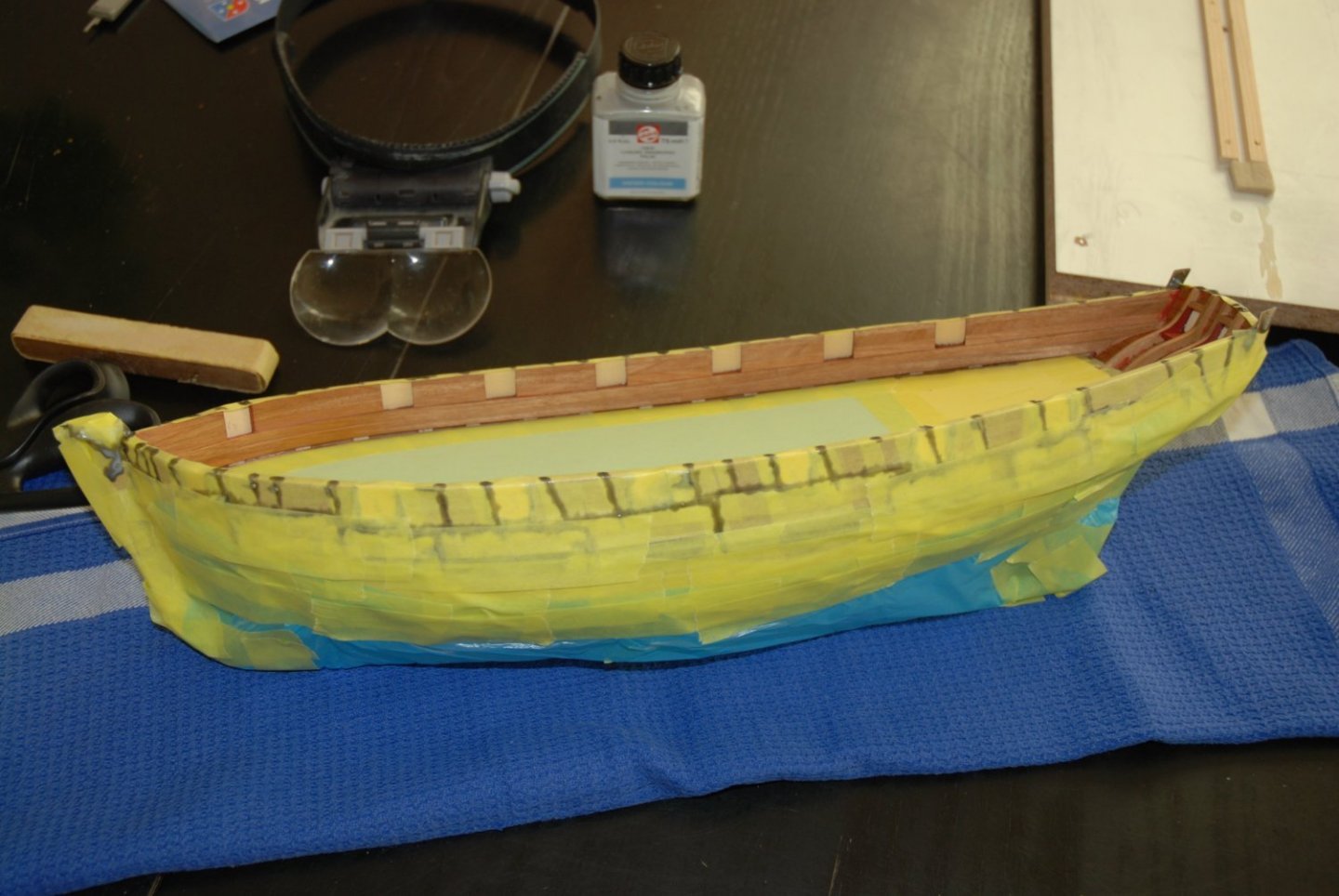
And the whole hull is protected. We often spend more time protecting what should remain color free than the coloring itself.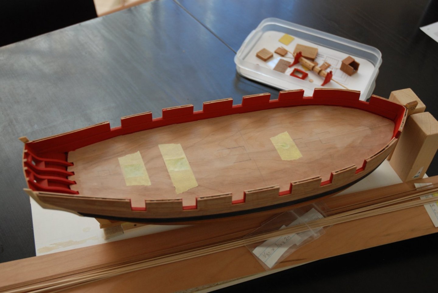
Rather satisfactory result. No trace of color on the hull.
I will be able to finalize the part of the hull above the wales by adding the fancy moldings then add the cap rail.- Mike_In_RI, Chuck, rafine and 14 others
-
17
-
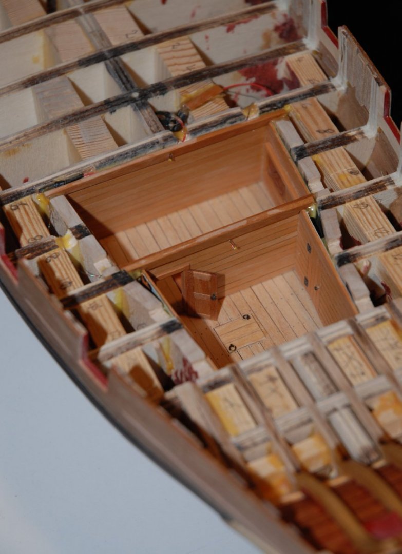
Thanks to all those who follow my work.
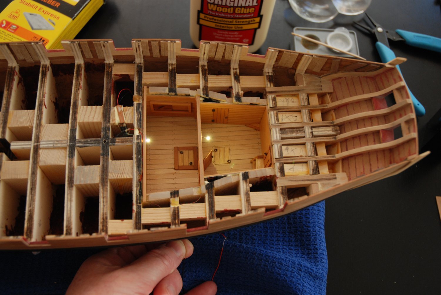
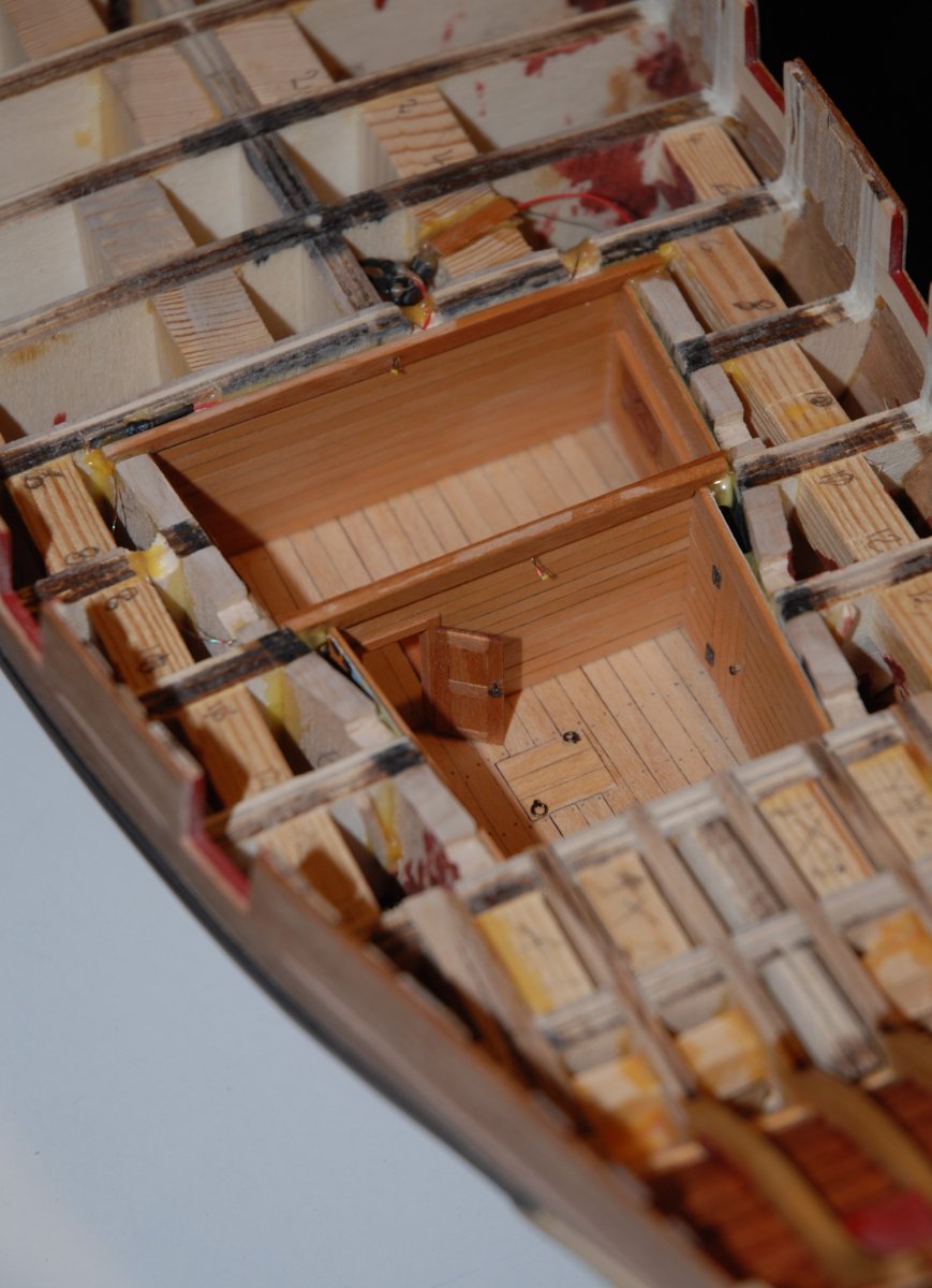
@Glenn, I had a lot of fun detailing the interior of the 2 rooms and adjusting the opening visible from the deck. And I am fortunate to be able to refer on this site to excellent reference models every time. Thanks again for your excellent log on the Cheerful.
@Will, it's true that the addition of the false deck marks an important step. All the internal structure is hidden and we will be able to detail all the fittings that will take place on the deck. It is indeed starting to look like a ship.@Johann, thanks for the kind words. Your work on the Creole is one of my references and I think many of us admire the quality and precision of your work. As for me, I still have a long way to go...
-
Unfortunately not.
I am currently working on my other project: the Cheerful cutter.
But I haven't forgotten this longboat. I will resume work shortly.
-
Thanks to all the people who are following this build and giving me precious advice.
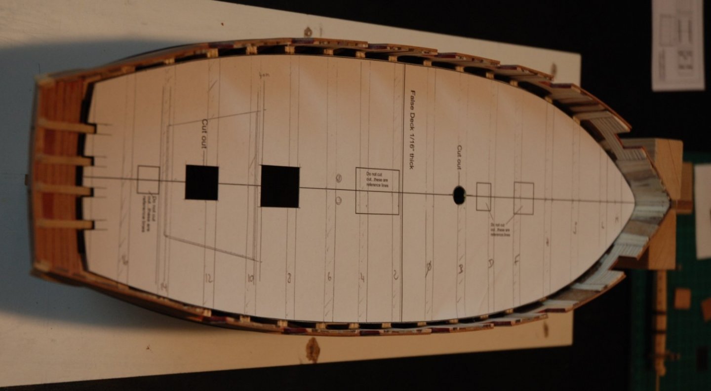
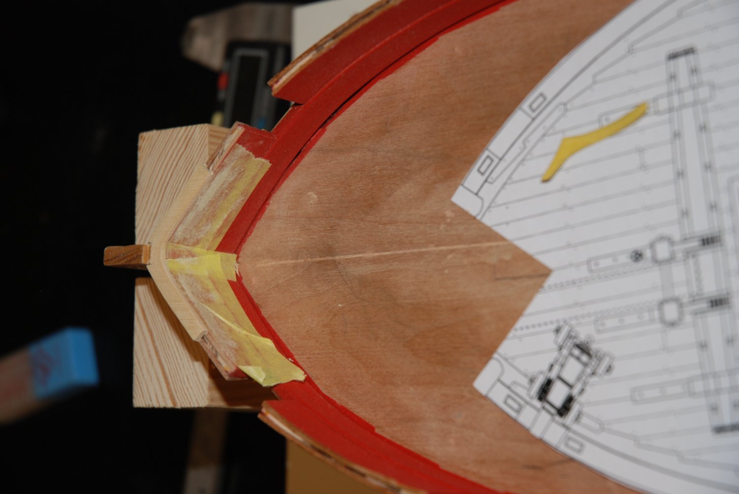
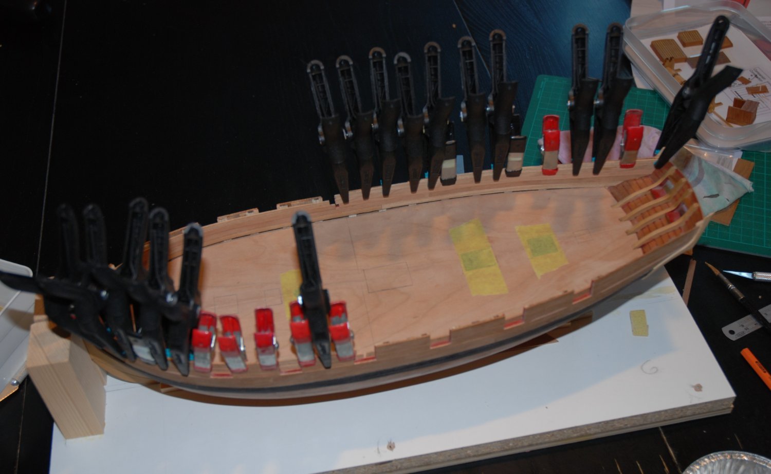
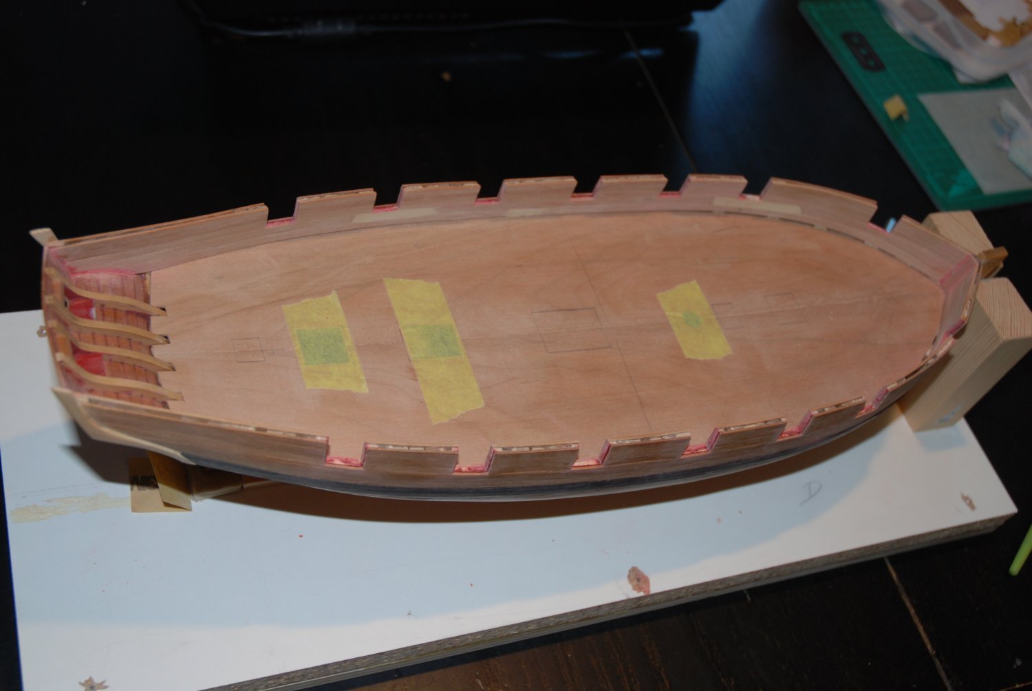
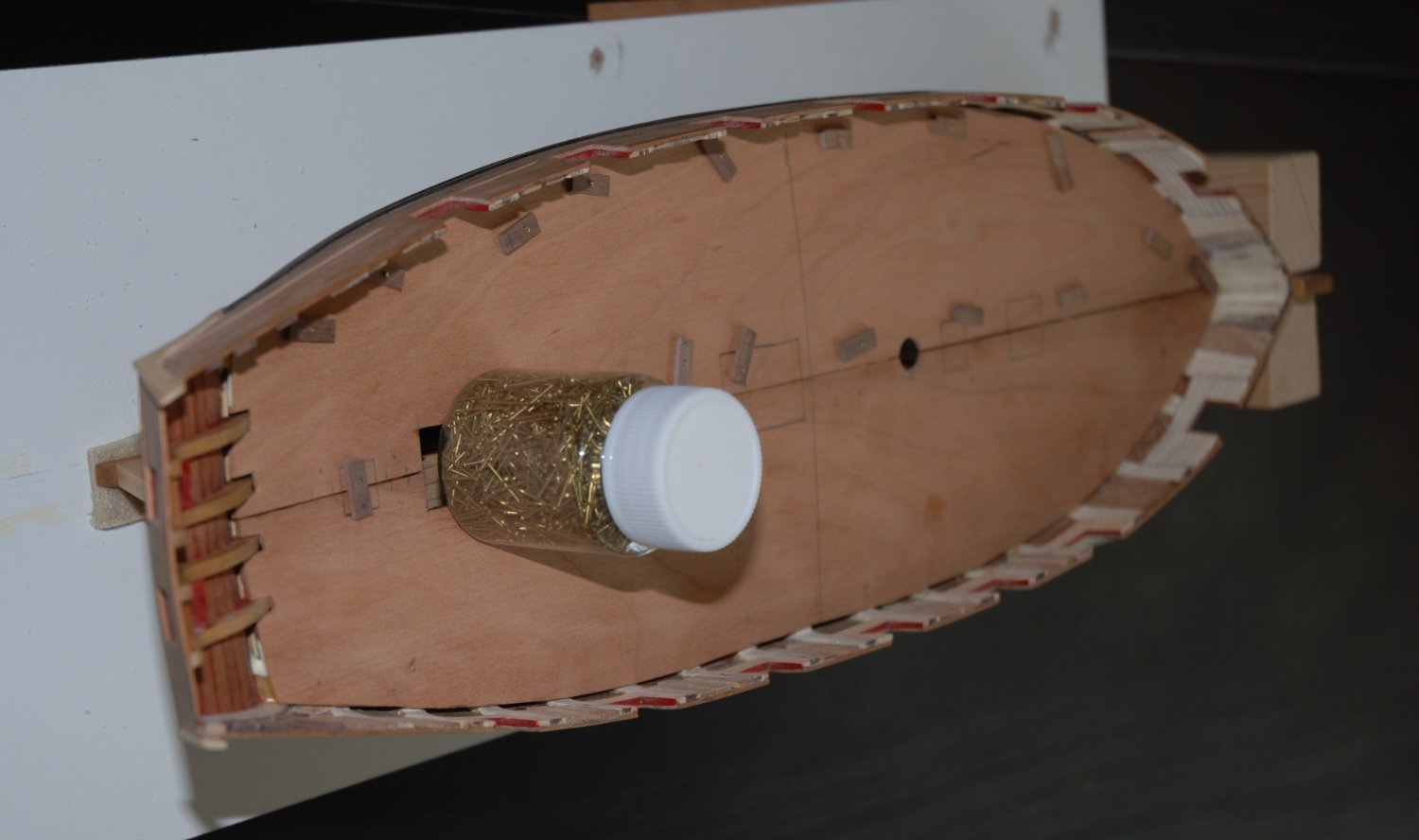
This week I put in place the false deck.
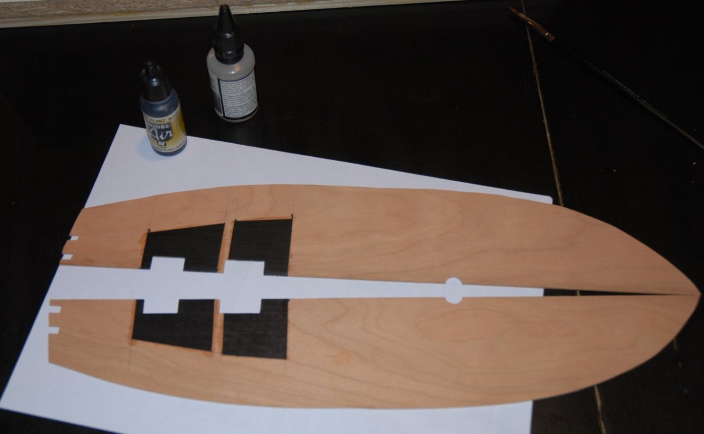
I followed the instructions precisely, so I started by adding multiples thin strips of protective tape on each side of the cut plan to adjust the false deck.
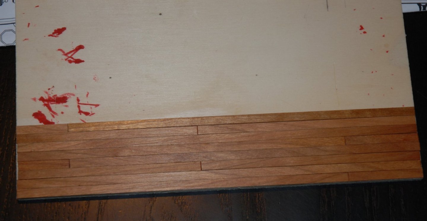
The final shape is transferred to two 1/16" cherry wood sheets that are temporarily joined with tape. I didn't have a large enough sheet and it also saves me from having to cut through the middle.
On Scrubbyjj427's advice, I painted the reverse side of the false deck in the areas above the two rooms to keep the light from coming through the wood.
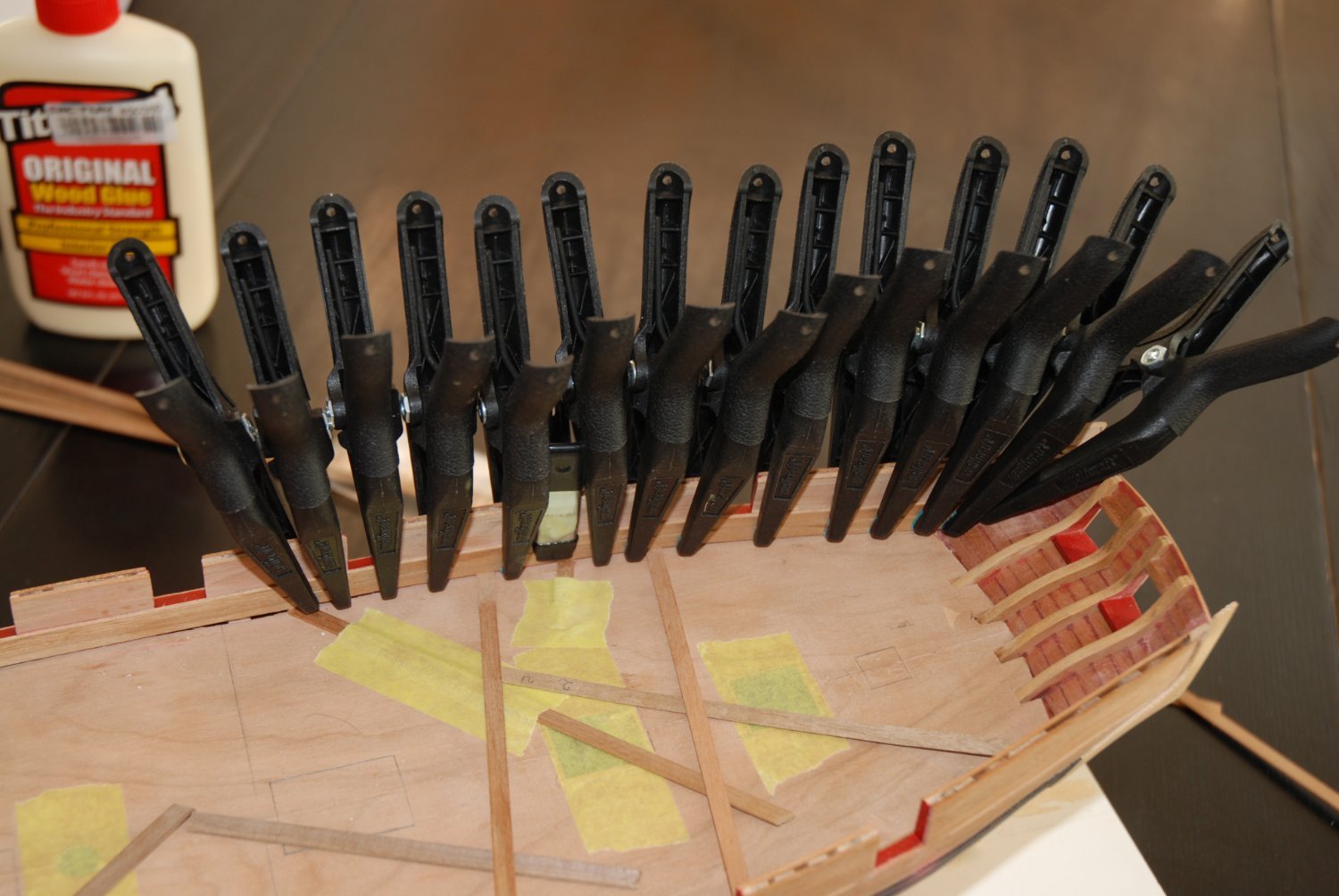
I glued the false deck in 2 steps so I could put the access ladder in place before gluing the second part. I was afraid to drop the ladder in the room if I proceeded to put it in place once all the false deck was glued.I know myself 😅

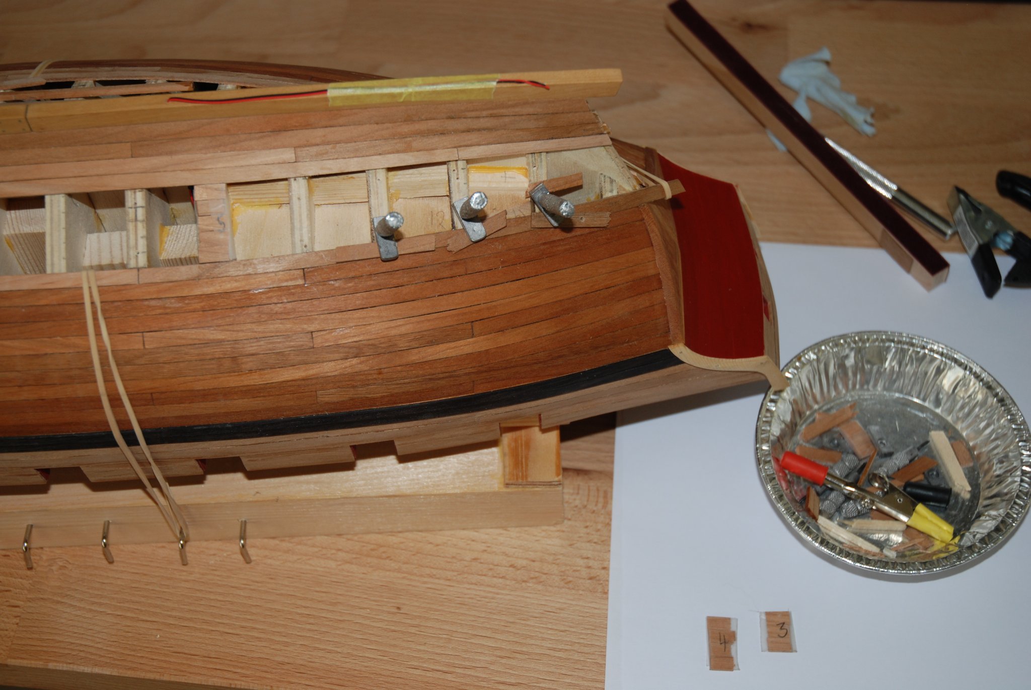
The false deck has been reinforced with small nails that will be removed once the glue has hardened. This ensures that the false deck adheres precisely to the bulkheads.
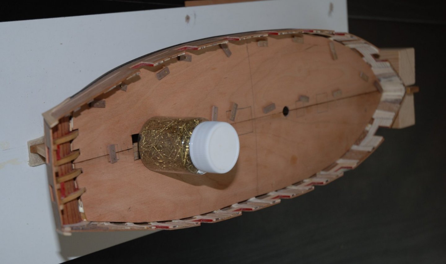
Once the nails are removed, the gaps and marks left by the nails or their extraction are filled with wood filler and sanded. I also take the opportunity to finish the 2 openings located on the false deck.
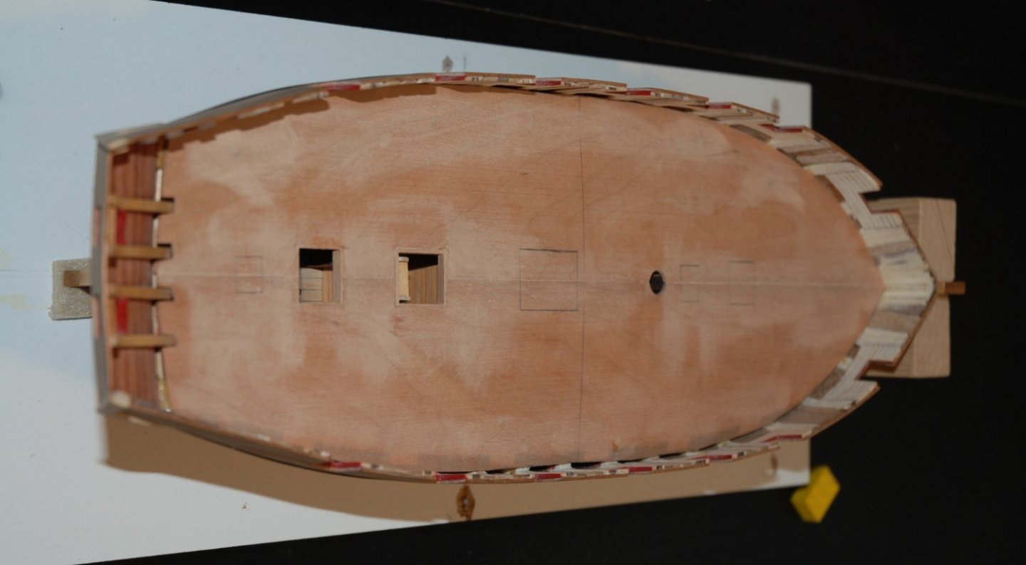
A final blank test of the various fittings.
I will now finish the internal planking of the bulwarks.
- WalrusGuy, FriedClams, bruce d and 11 others
-
14
-
Thank you Bob, Glenn and Mike for your kind comments and thank you to all the 'Likes'.
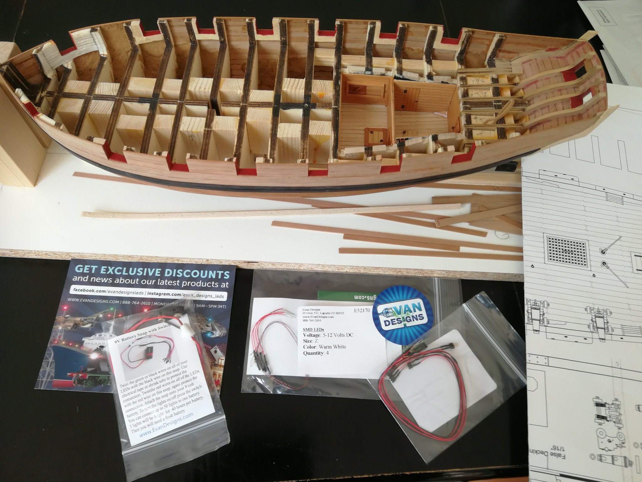
I finished the assembly of the electric Evans Designs leds. I will then be able to prepare and glue the false deck of the ship.
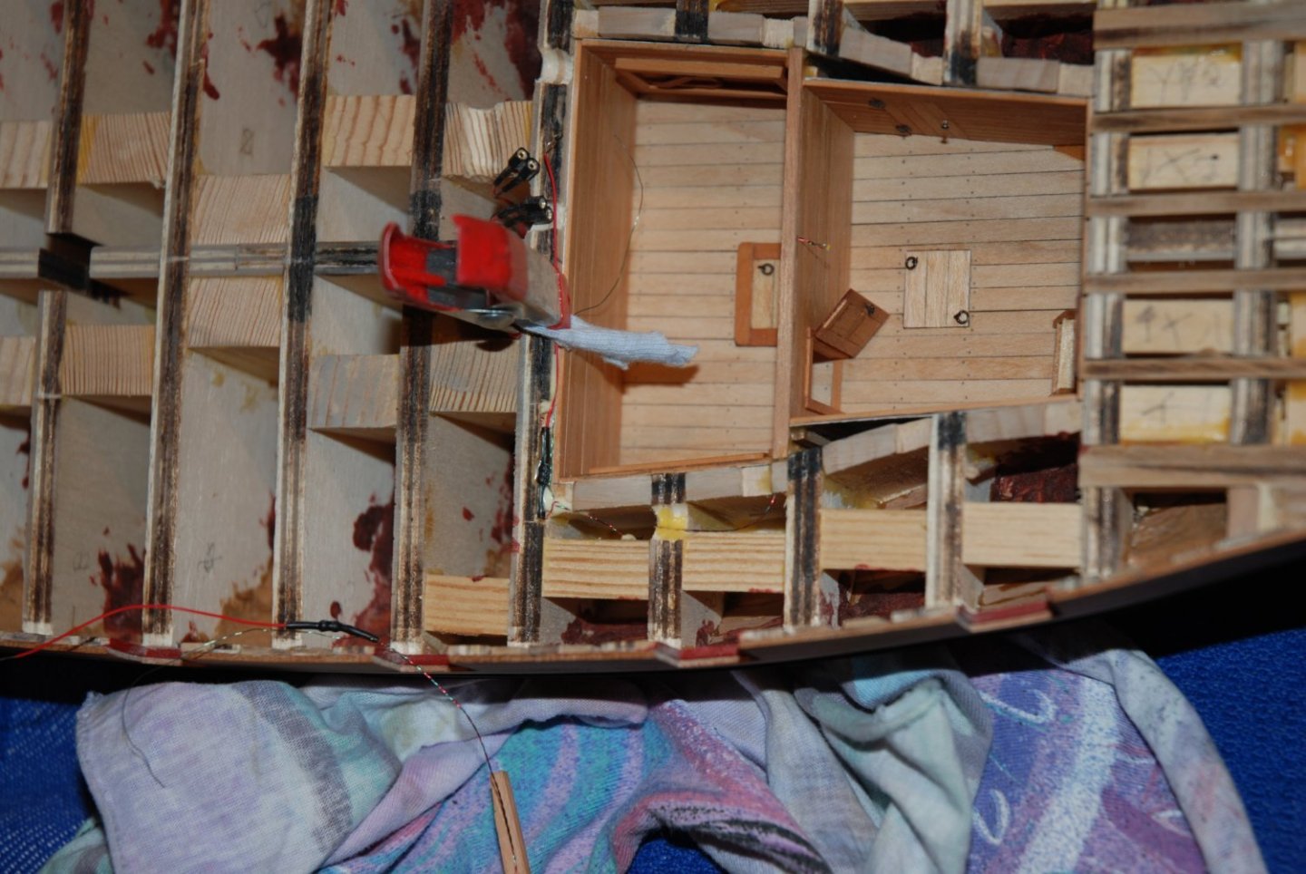
A small test once the assembly is completed. It works 😃. A big thank you to scrubbyj427 who made me discover these great little leds from Evan Designs in his beautiful build log of the Winchelsea frigate.
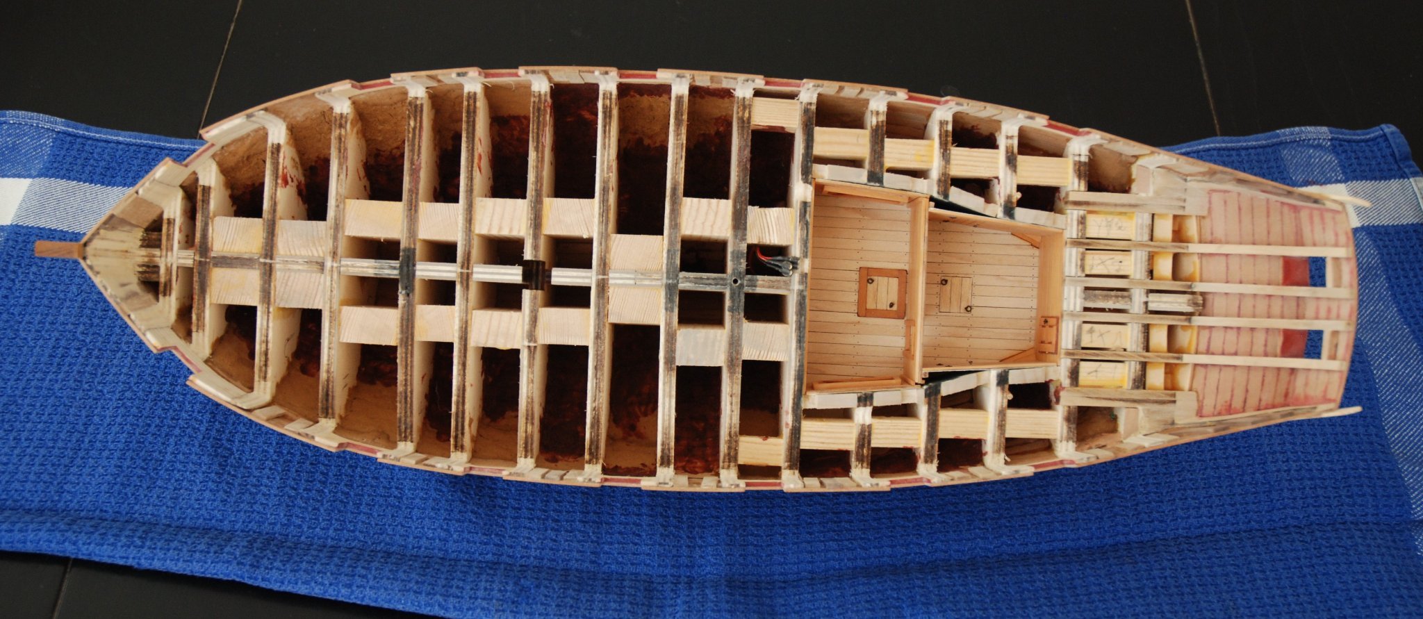
The last details have been added: the open door between the 2 rooms and the small ladder that gives access to the door to the bread room.
Next step: installation of the false deck.
-
Great job on these pumps. It's beautiful.
-
Thank you Glenn, Ron and Allan for your great advice and thanks to everyone who is following this build.
I will definitely be testing for hull treenailing. I've already prepared a reproduction of the planking and I'm still waiting for my order for the drill bits (Covid has slowed down package deliveries again...)
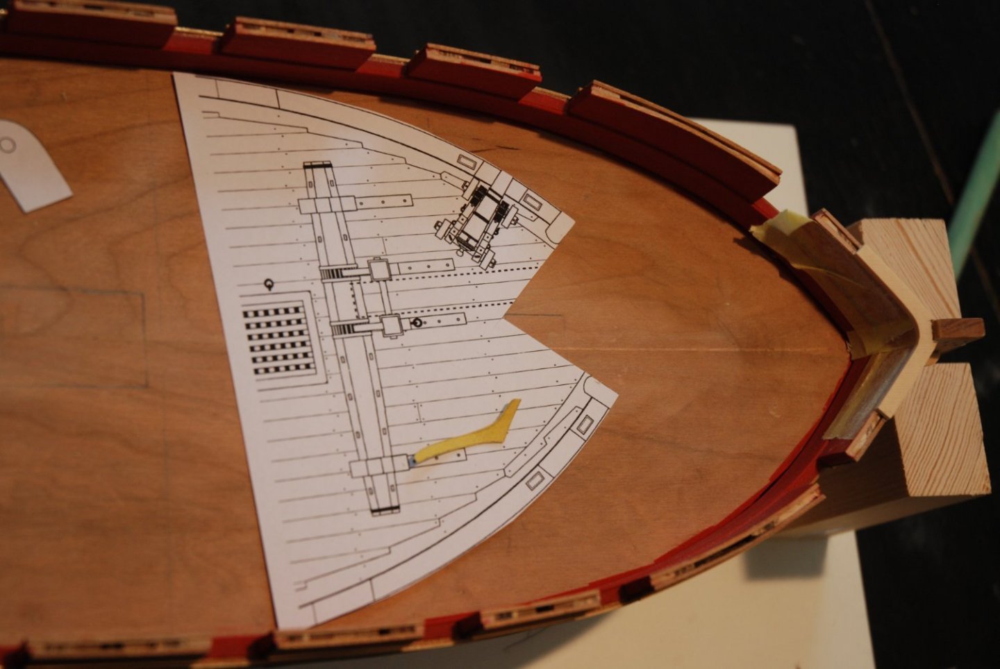
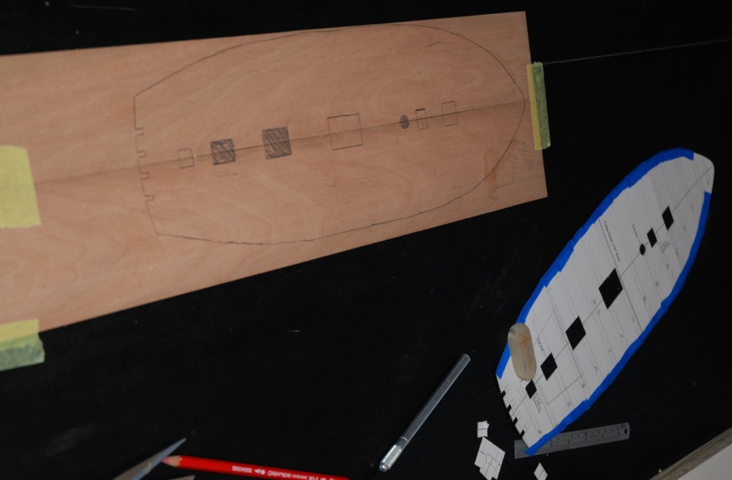
In the meantime, I am making progress on the preparation of the cutter deck.
I glued a copy of the deck plan onto card stock and cut out the elements that will allow the two rooms I detailed to be seen.
I still need to add tape around the edge to get the final shape of my false deck so I can cut it out of a 1/16" cherry sheet.
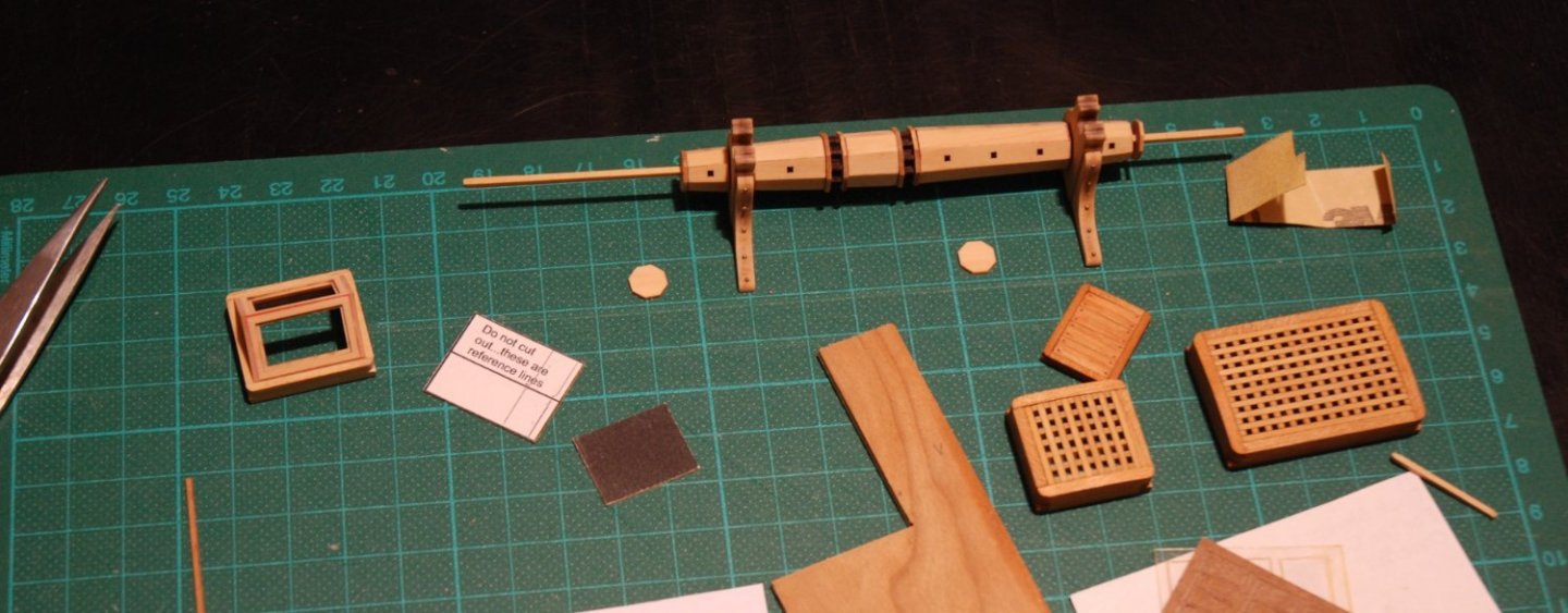
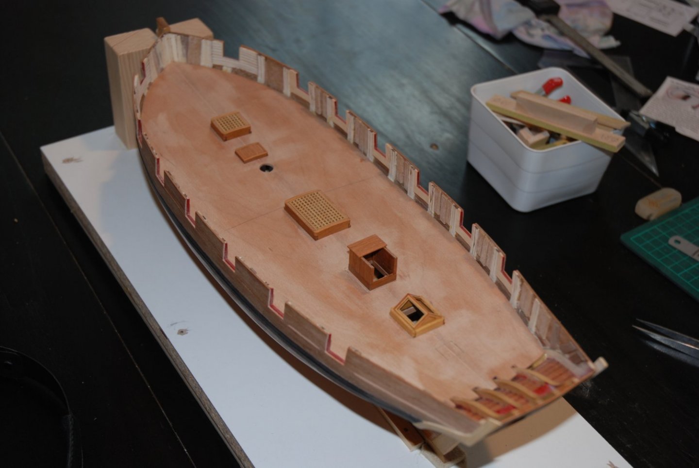
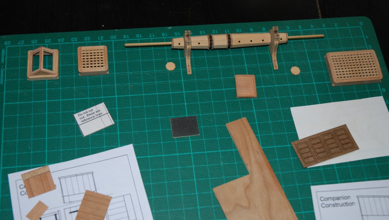
I continued the assembly of the various fittings that will be on the deck. The gratings come from Syren and it is again a pleasure to assemble them.
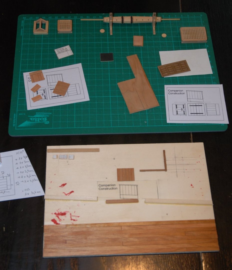
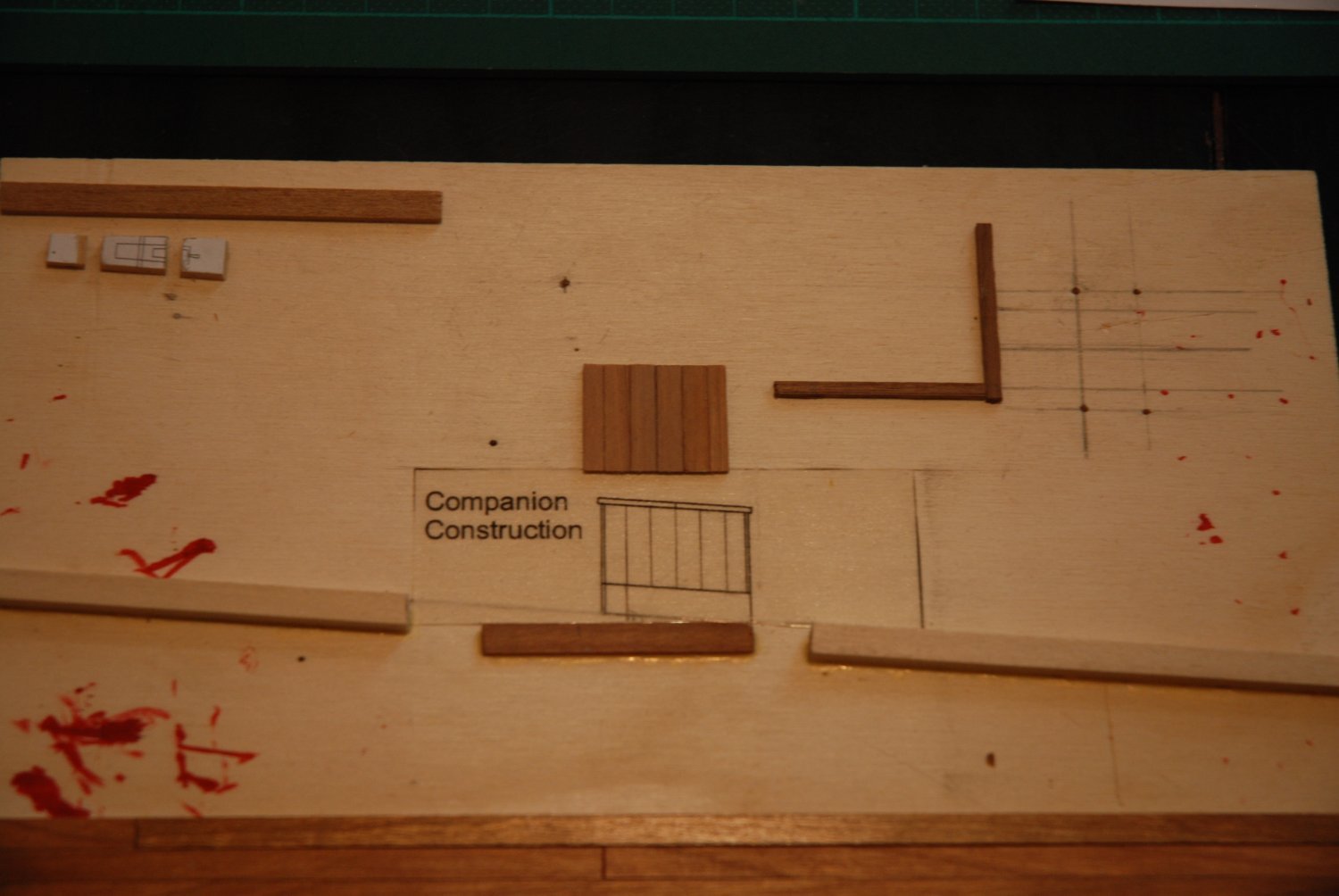
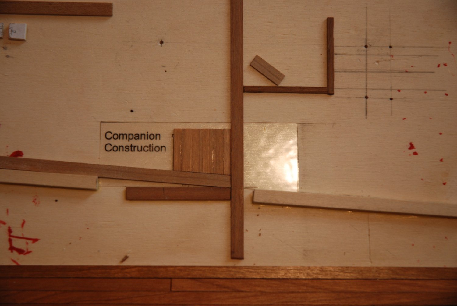
And finally, I started the assembly of the companionway. Since I'm going to leave the doors open, I have to be quite precise in the assembly.
I quickly realized that it's not a simple cube that needs to be assembled, because I have to take into account the slope ('tonture' in French) of the deck.
Reading the excellent log of glbarlow confirmed me on this question.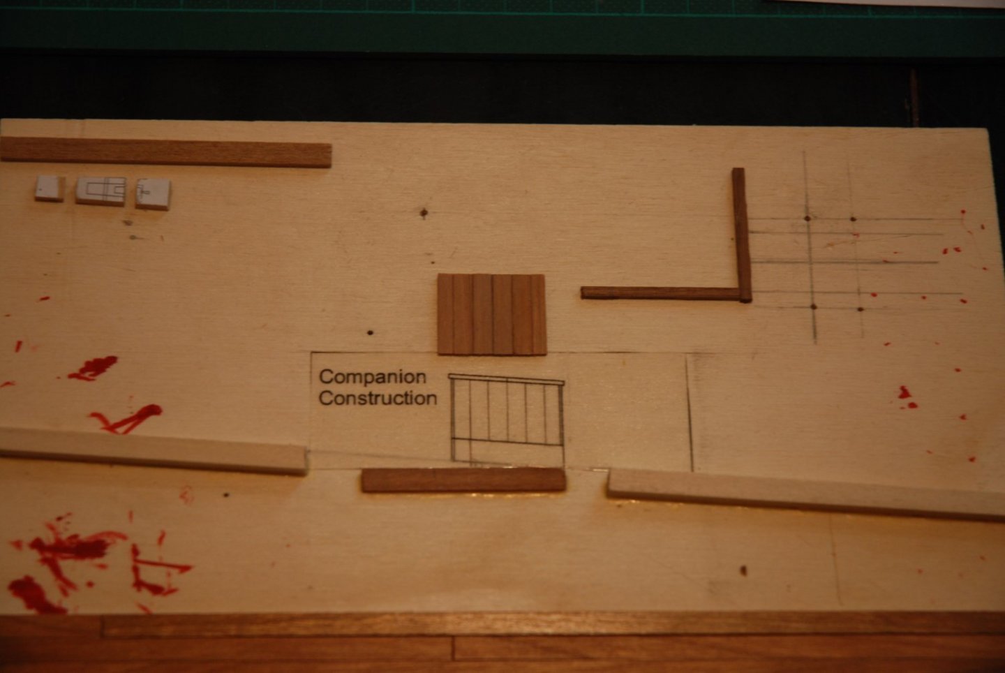
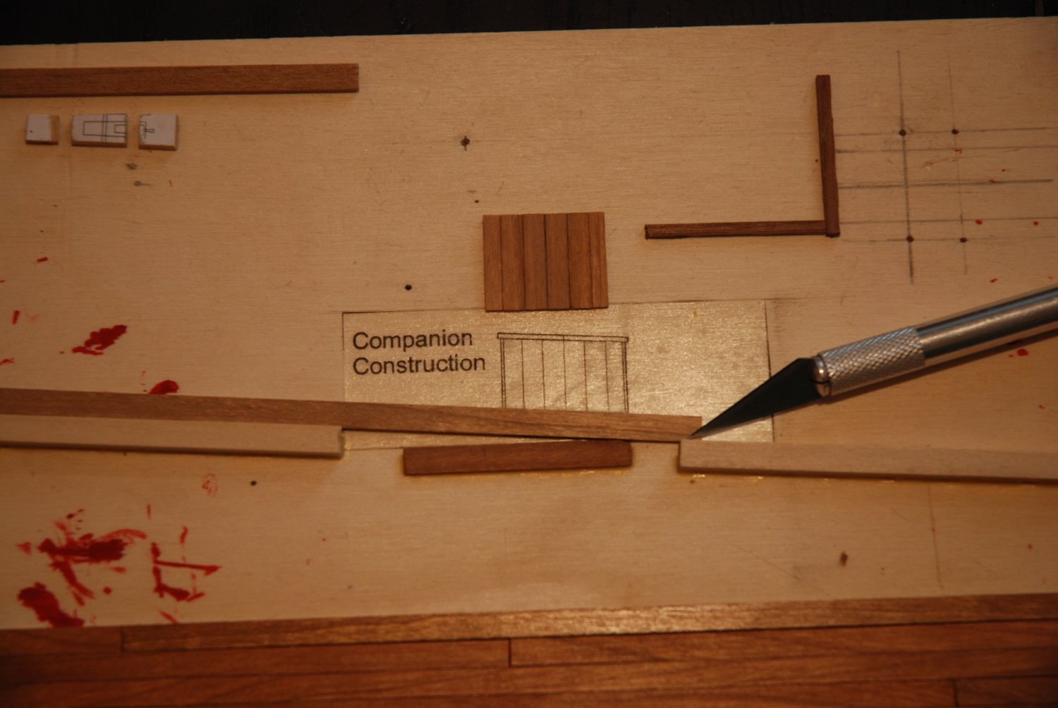
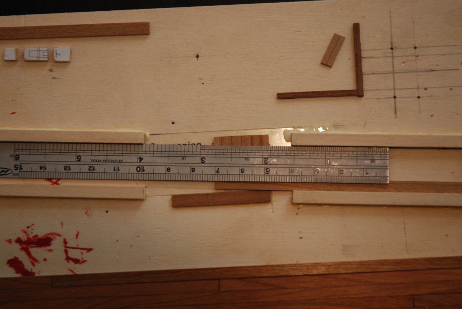
So I quickly developed a jig to facilitate the assembly and especially to have precise angular cuts. A photocopy of the plan was made on a clear self-adhesive film.
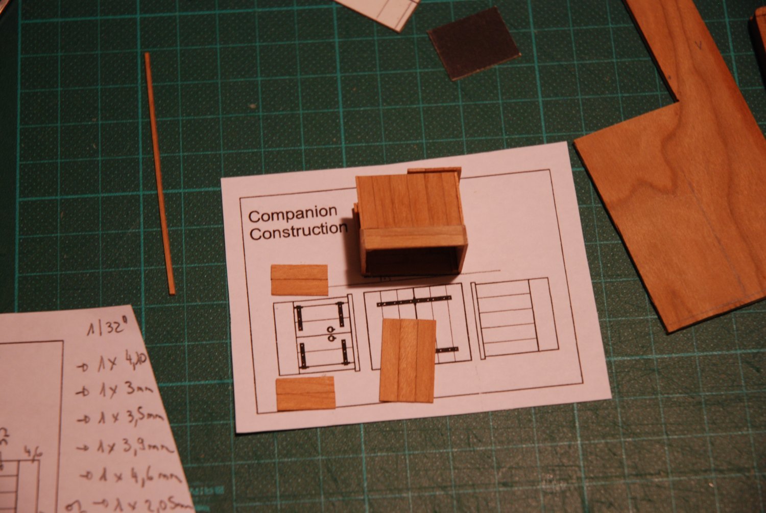
The two side pieces were mounted at right angles. They are made of 6 planks of 1/32" but are higher than the plan.
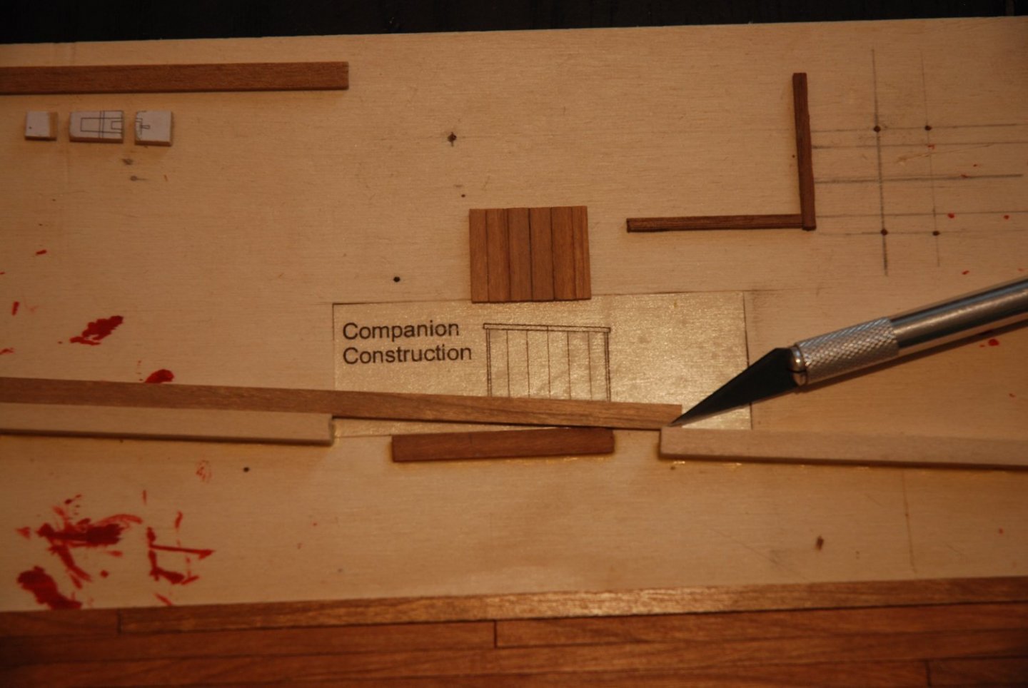
I can use my jig to make the various cuts.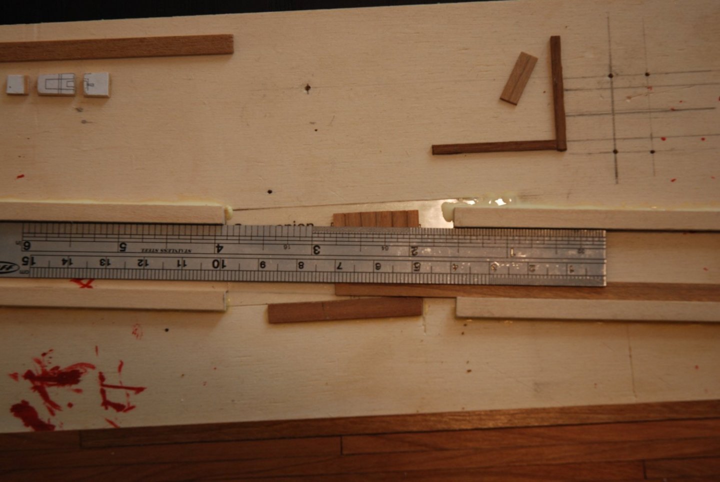
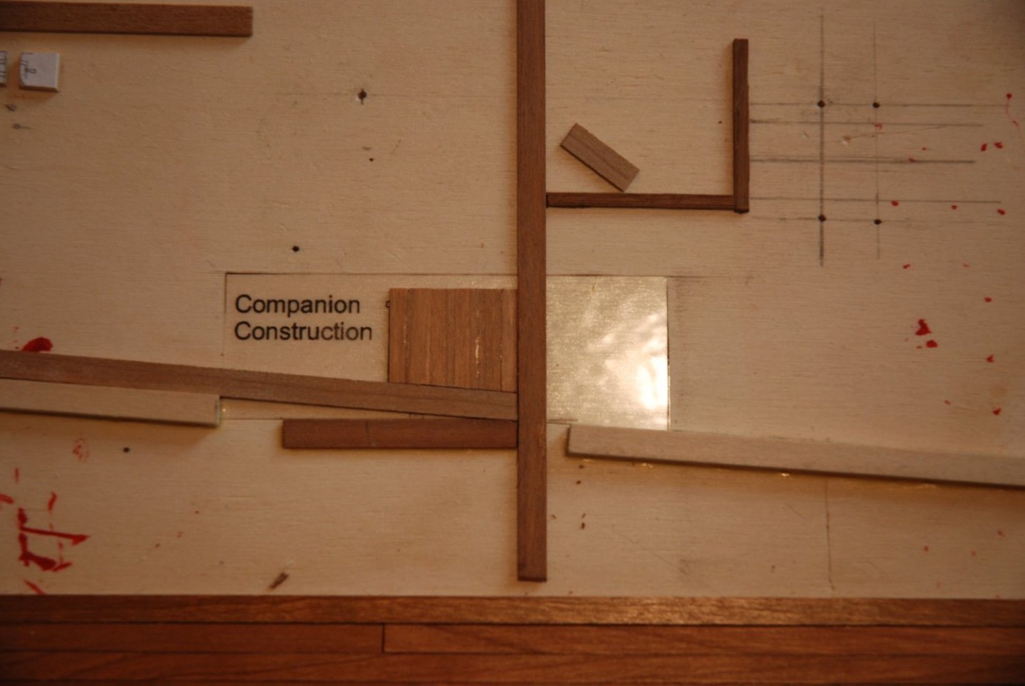
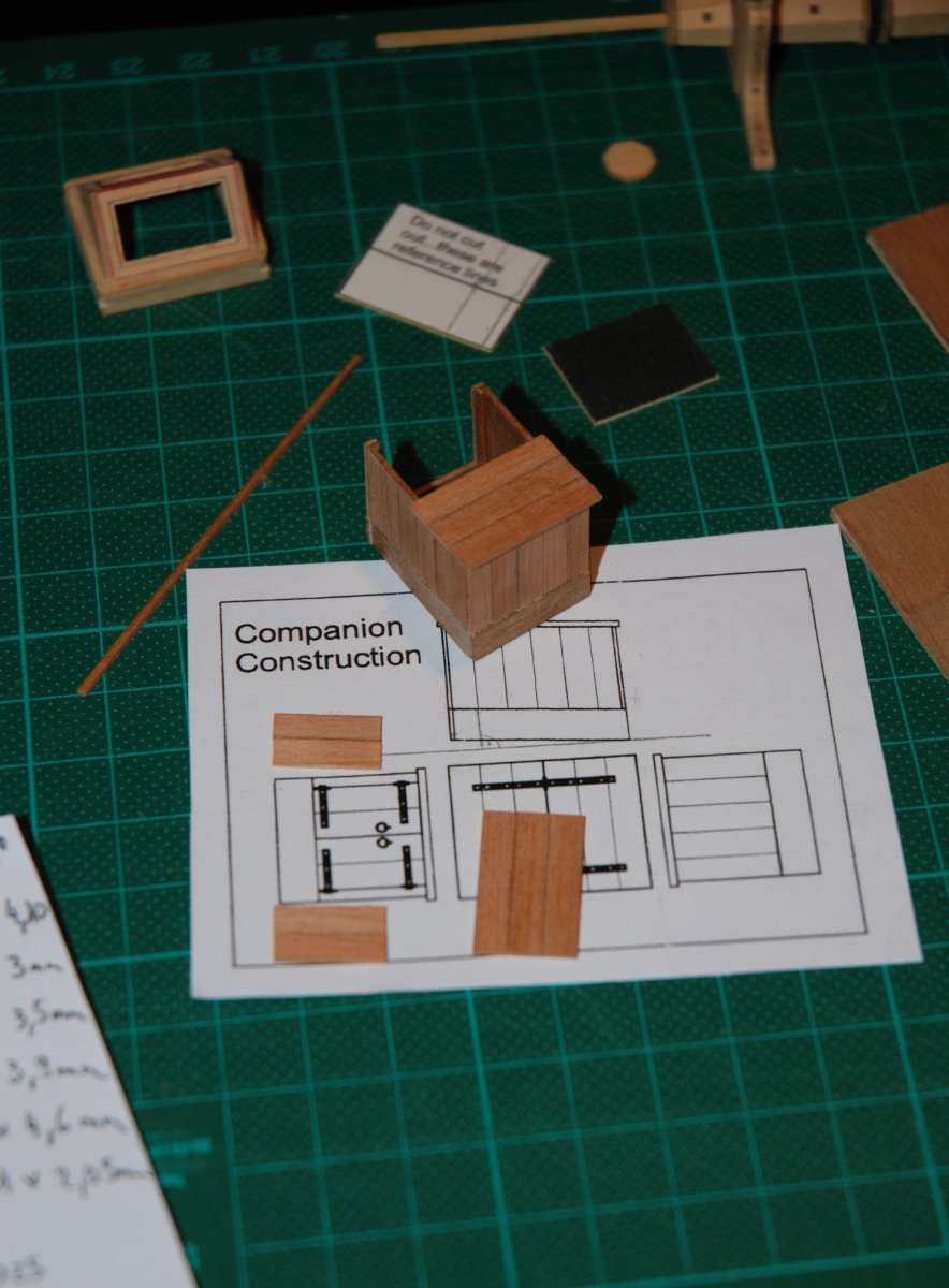
For the height, I simply added again 2 pieces of wood at the top of the companionway that follow the slope of the deck.
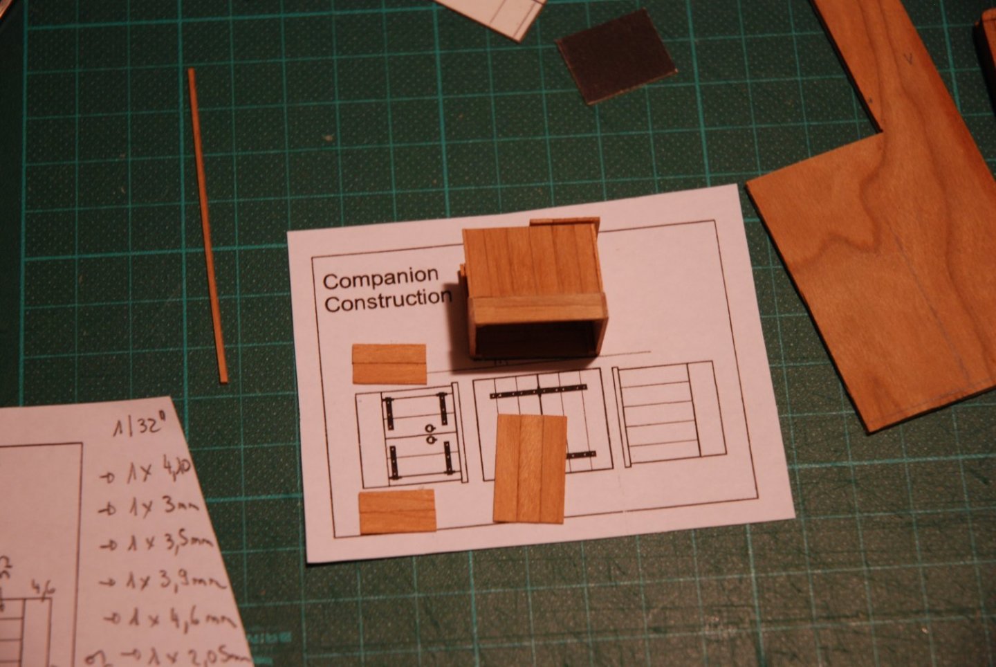
The result respects the plans quite well. I am trying to work cleanly because I am thinking of not painting the companionway and leaving it in natural wood.
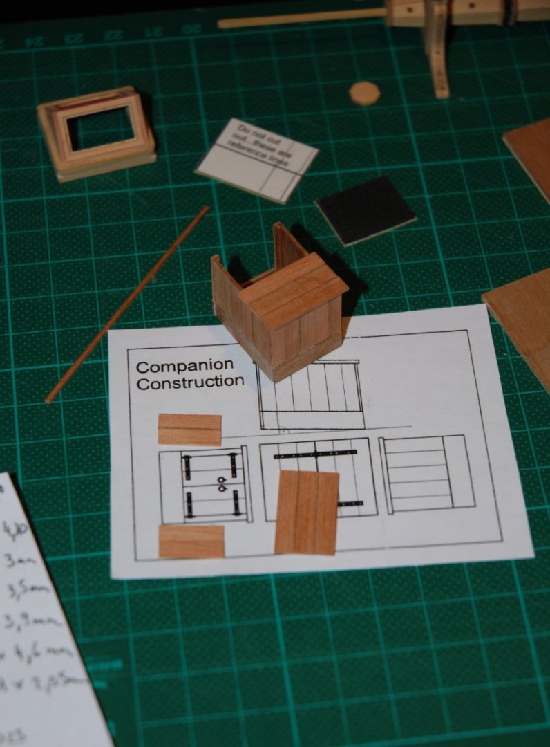
I still have to finalize the companionway by adding the open doors.
- Saburo, FriedClams, GrandpaPhil and 9 others
-
11
-
 1
1
-
Great job! These modified hatches are really beautiful and the choice of the black color is perfect.
Happy New Year!
- Blue Ensign and mtaylor
-
2
-
Wonderful! It is always so precise and perfect!
-
A promising new project. No doubt it will be fantastic! Merry Christmas.
- FrankWouts and Ryland Craze
-
2
-
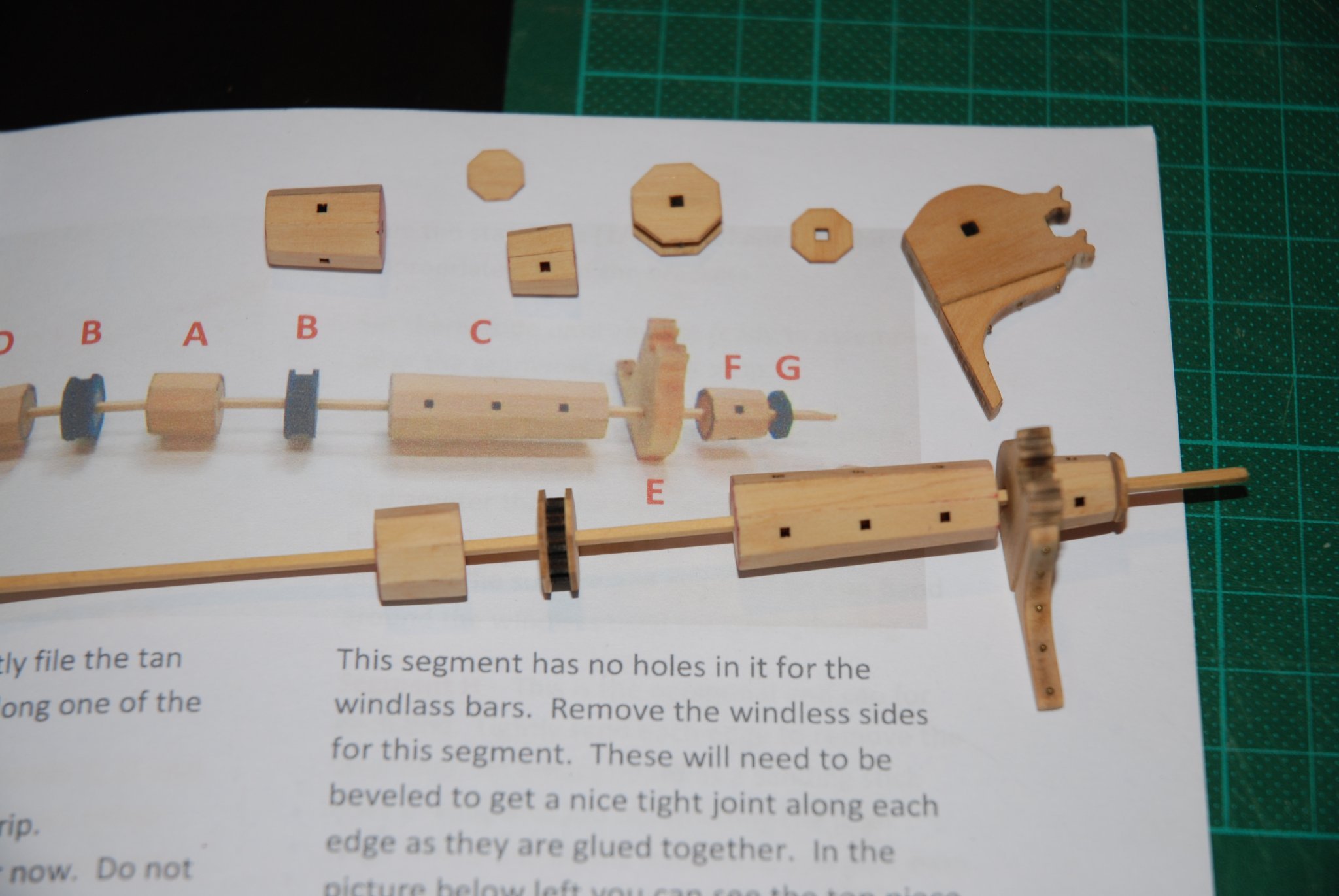
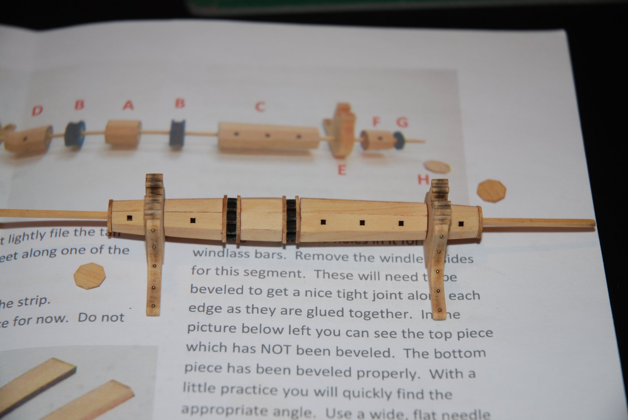
As I am still waiting for a package of #78 drills for the treenailing, I decided to assemble the different fittings of the deck.

They are mini projects in themselves. Again, we can only thank Chuck for the quality of these mini kits and for the precision of the assembly instructions.
It's a real pleasure. Just take your time and follow the instructions precisely. What a pleasure!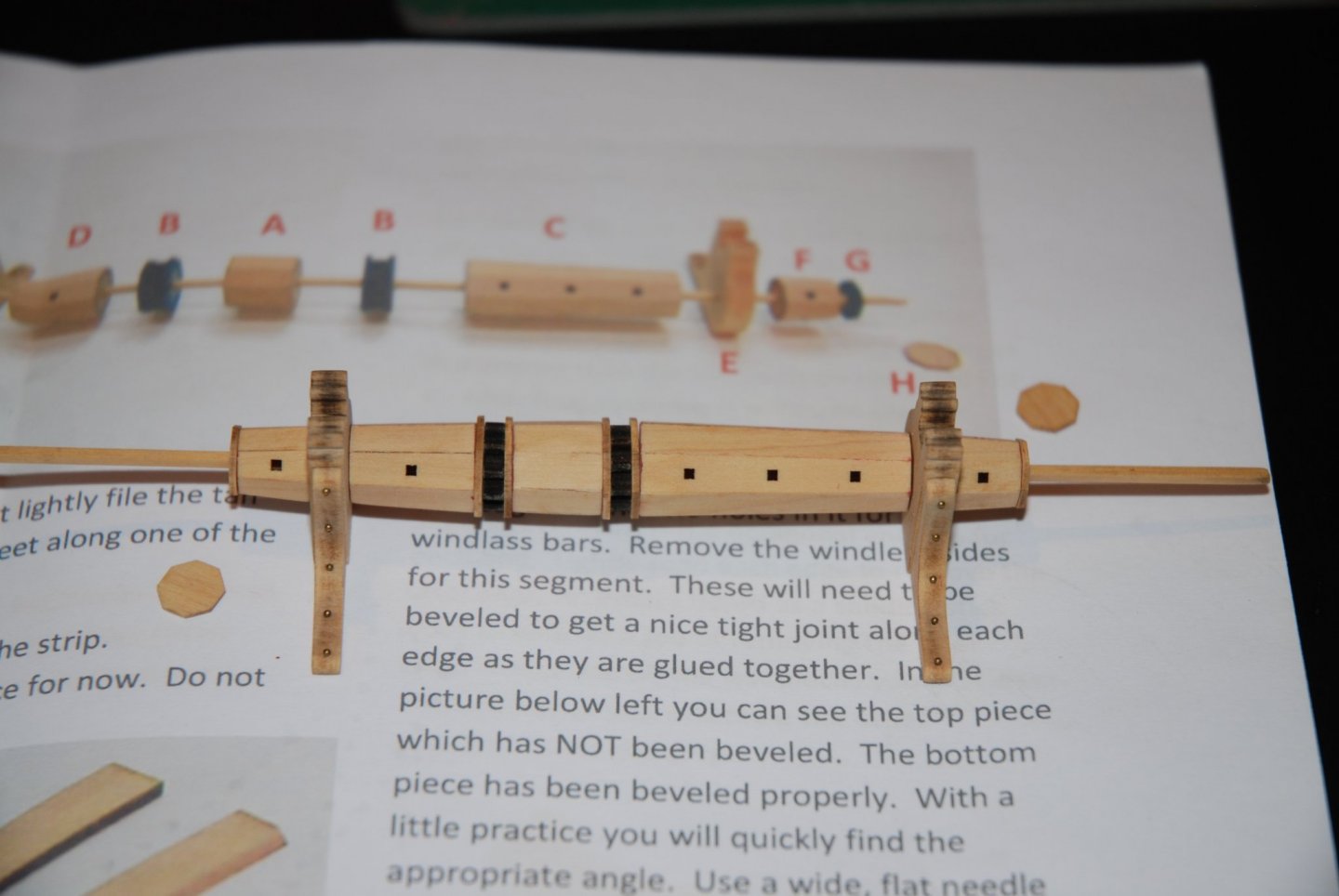
The windless will definitely be mounted once it has been painted. I will wait until the internal planking of the bulwarks is finished to paint all the elements at once. For the moment nothing is glued.
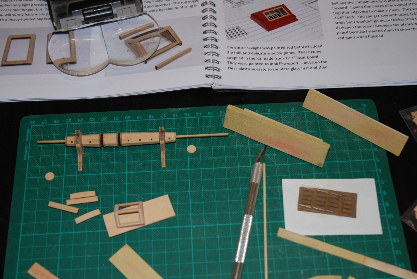
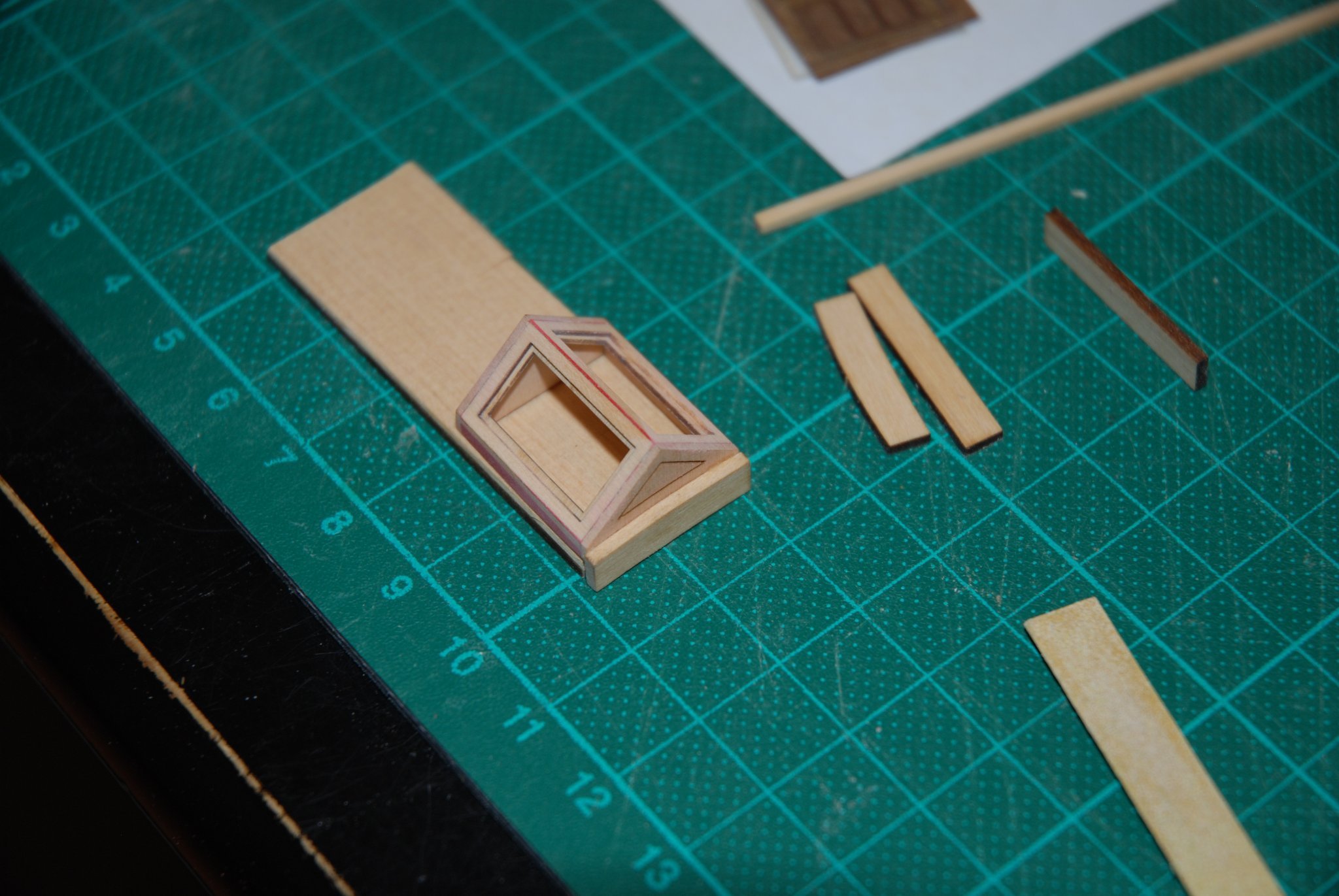
I started to mount the skylight.
Again a lot of fun to work on this element. And with the extra parts provided, no worries in case of mistakes (I had to redo one of the top frames because I managed to sand on the wrong side...)
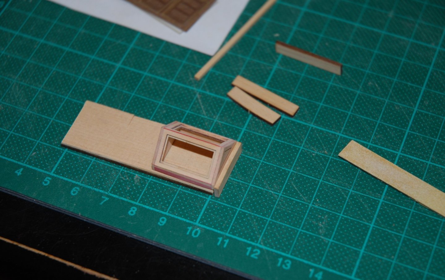
I filled all the gaps and sanded the skylight thoroughly before mounting the coaming.
As usual, I tint the woodfiller in the final color of the element, which allows me to control my sanding more finely.
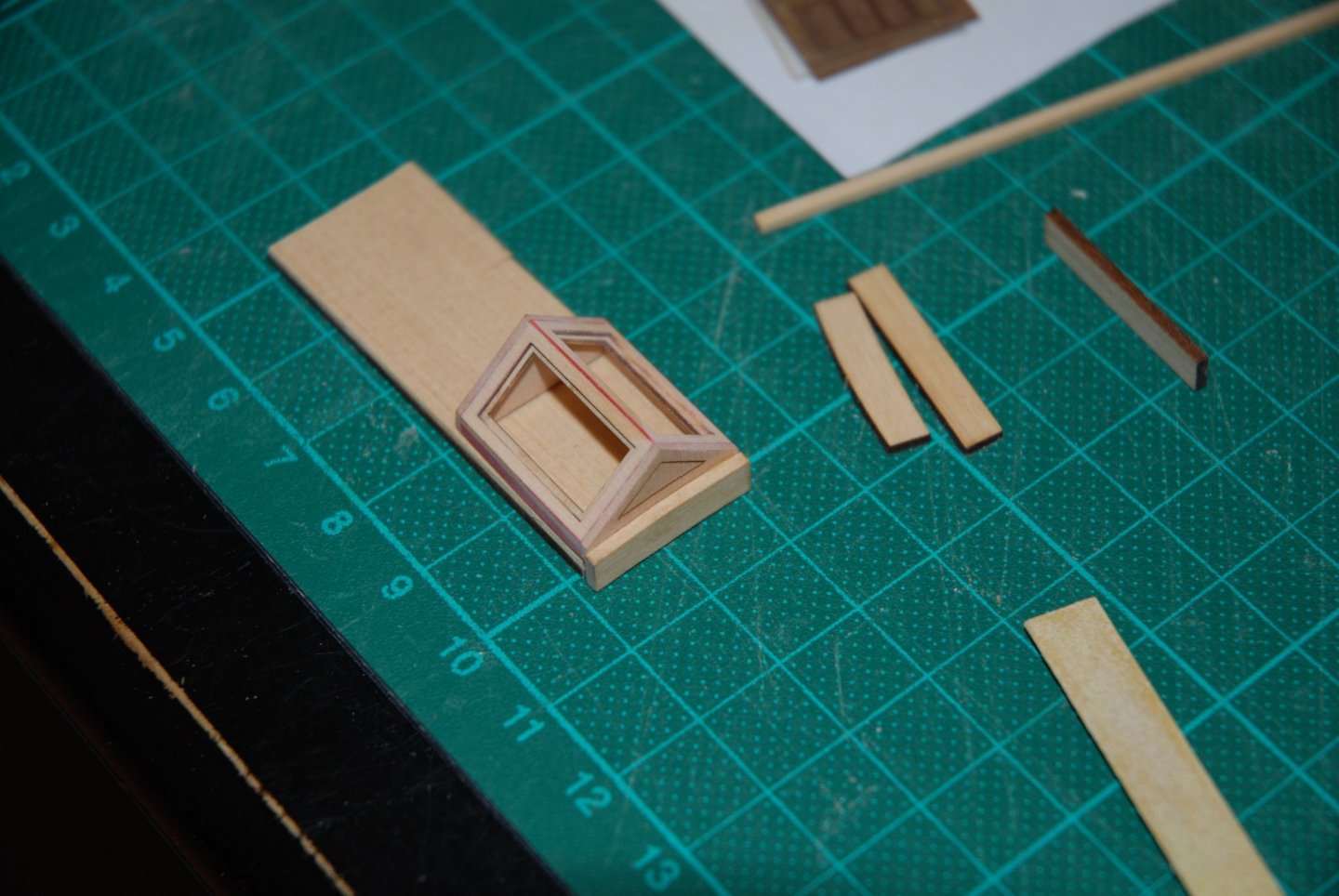
For the coaming assembly, I put the skylight on a wooden board to simulate the thickness of the deck planking.
Once this fitting is complete, I will mount the gratings.
Merry Christmas to everyone 🎄
- allanyed, Thukydides, GrandpaPhil and 13 others
-
16
-
A beautiful model for your birthday 😃.
Congratulations! This is really a great model with lots of personal details. This Fifie is absolutely a little gem.I look forward to your next model. Any ideas yet?
- BobG, WalrusGuy and Ryland Craze
-
3
-
Thank you to all the 'Likes' and thank you for your kind words.
Bob, I agree with your opinion on cherry wood. It is a warm colored wood. I still have to find the right color of wood filler for the treenailing.
I will proceed with testing as soon as my #78 drill bits arrive.
- BobG, FriedClams and Saburo
-
3
-
Thank you to all the 'Likes'.
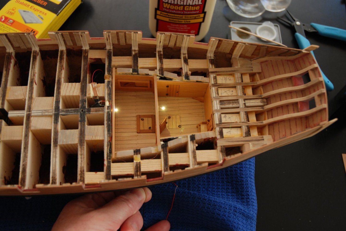
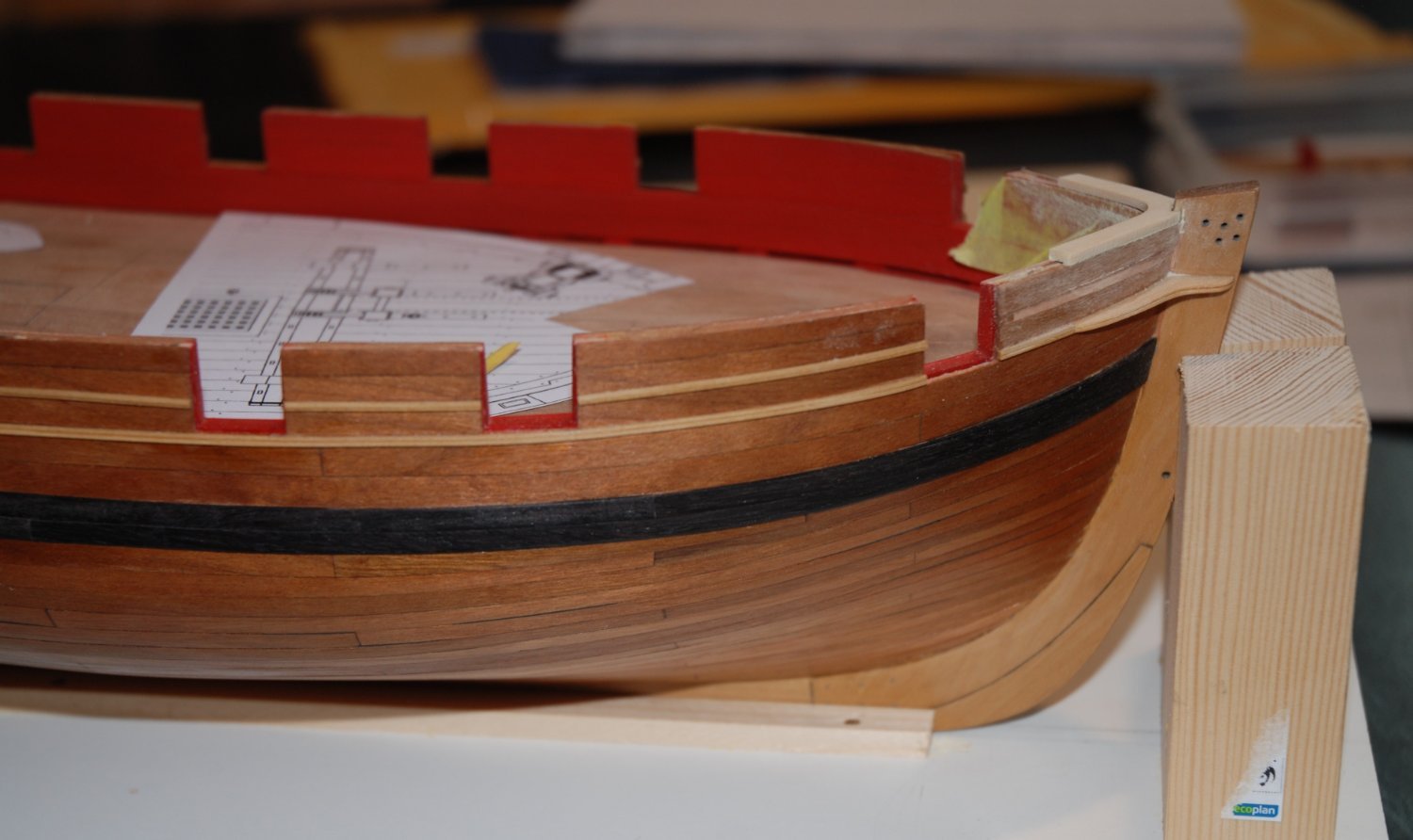
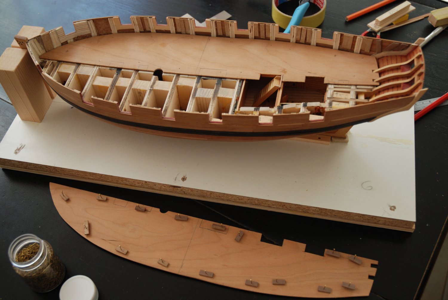
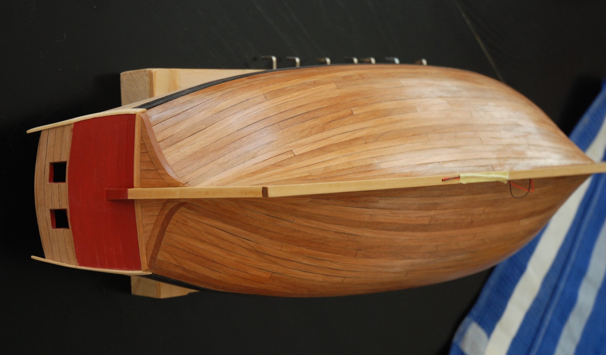
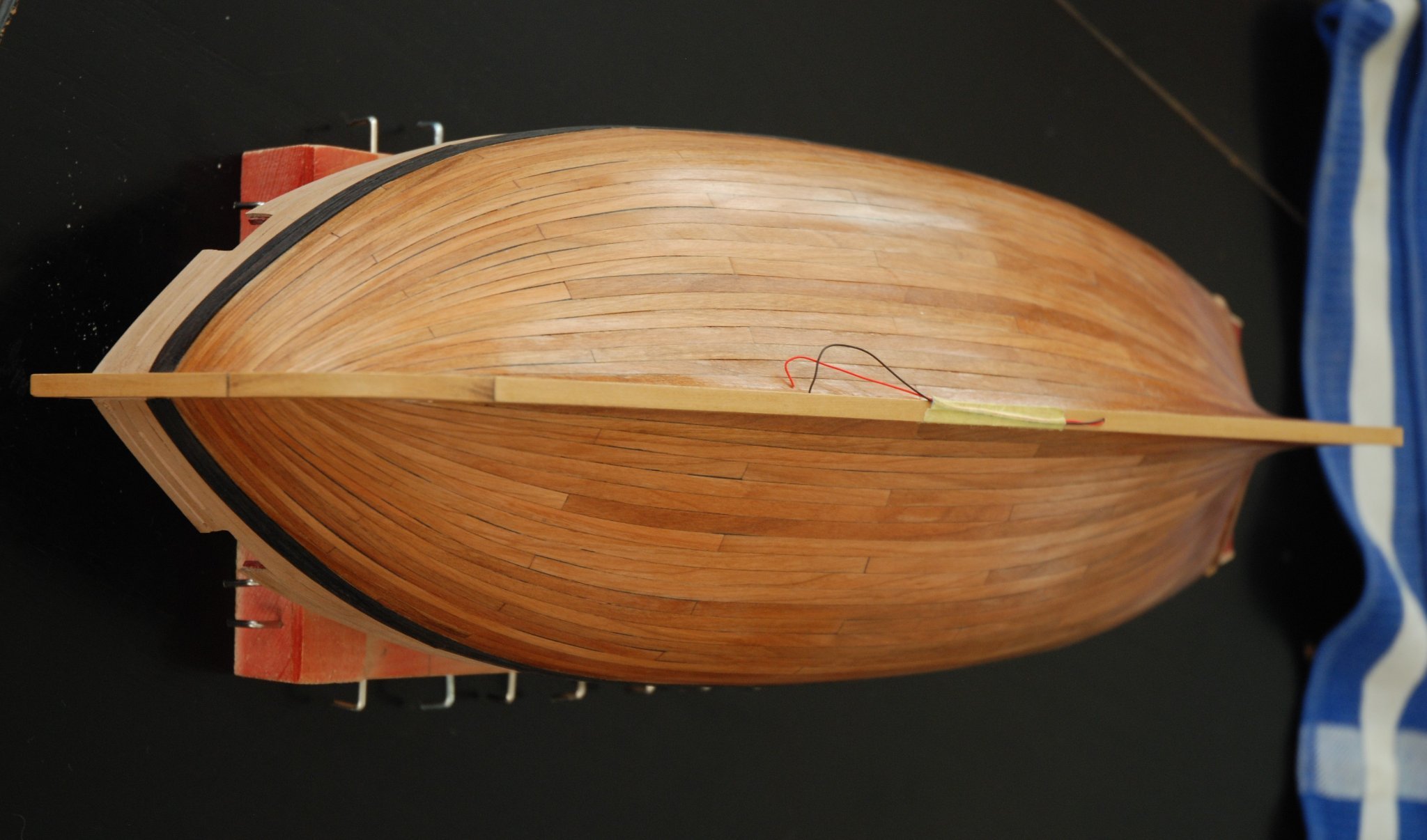
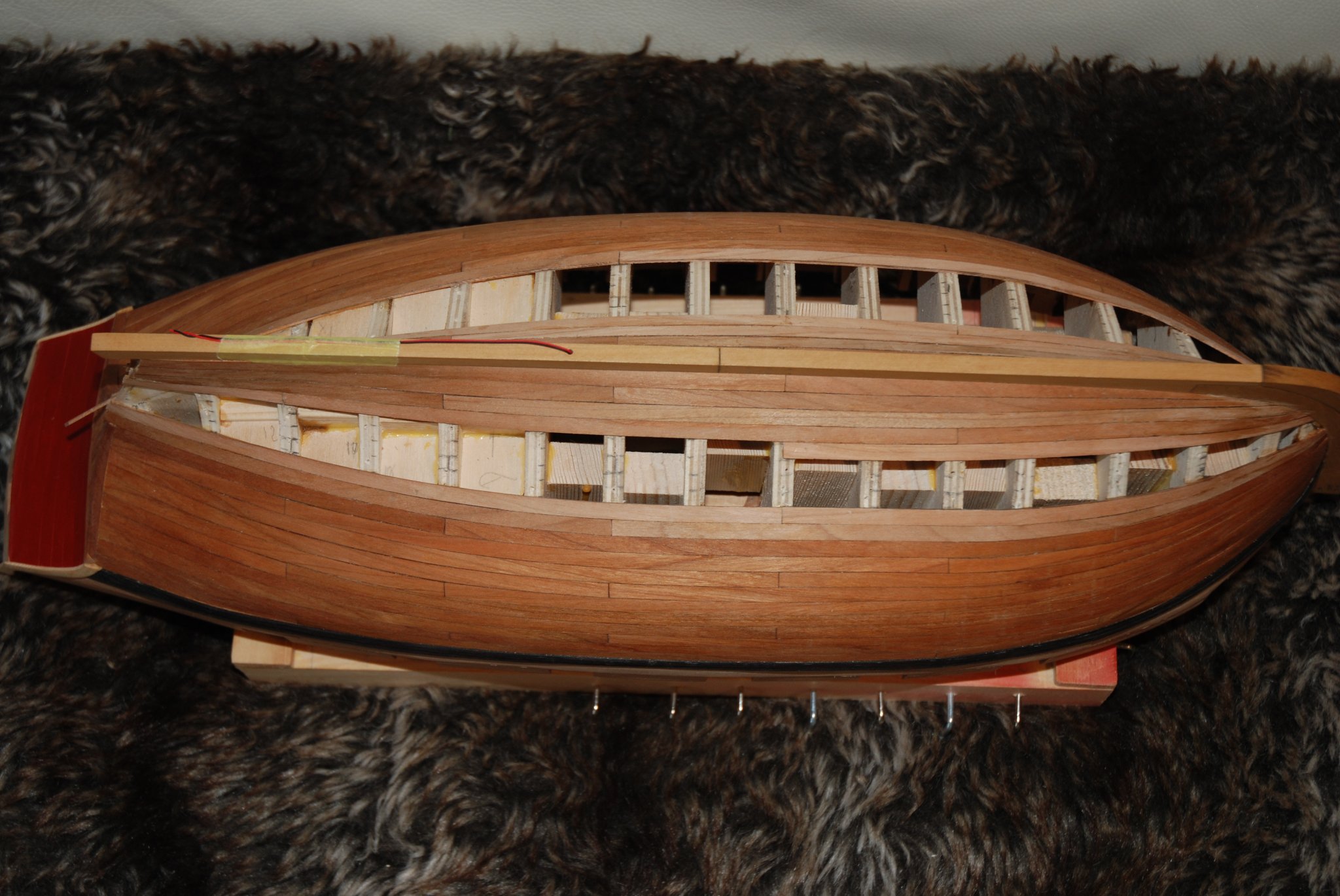
With the critical period finally over at my job, I was able to devote some time to my hobby again and finally finish planking the hull.
A good step passed. 🙂
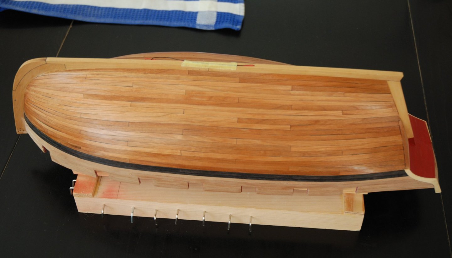


I decided to proceed to the treenailing of the hull. But I unfortunately broke the only drill bit of size #78. While waiting for a new batch of drills to be delivered, I decided to proceed with the last task producing a large amount of sawdust: to thin down the bulwarks inboard.

I started by roughing it all up with my Proxxon rotary tool. Then I finished the process using various home-made tools on which sandpaper was glued.

You will notice that to consolidate the planking of the hull, I coated the inside with a thin layer of woodfiller.
I can now proceed to the installation of the false deck. -
What great news! A 1/4 scale POF model of a reasonably sized ship and what's more by one of the most innovative designers.
I think there are many of us waiting for this moment!
I'm getting ready for some great hours in my future retirement 😄
-
Wonderful! What care taken in the quality of the details! It is always more beautiful.
- FrankWouts, Jack12477 and Chuck
-
3
-
-
The work is progressing slowly because unfortunately my job takes up a lot of my time these days and I can only devote a little time to my hobby.
However, I have made some progress.
The electrical part has been installed in order to light the two rooms.
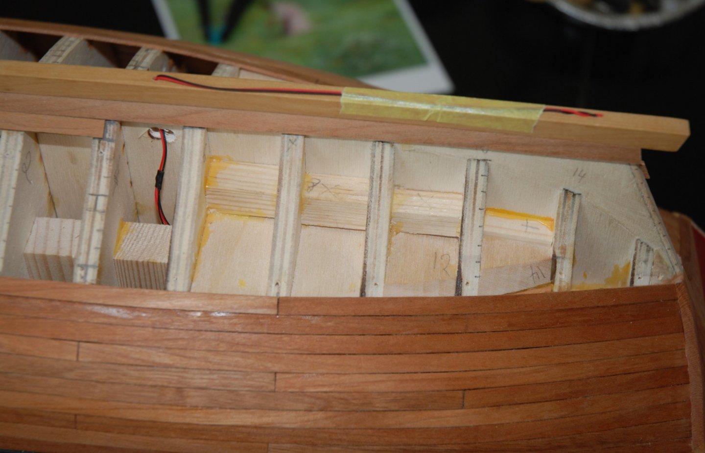
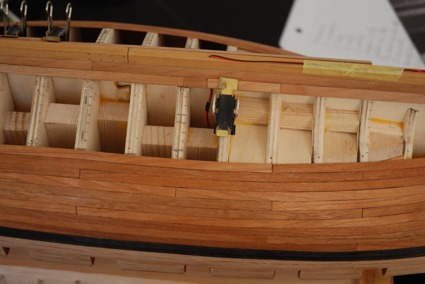
And the planking of the second belt has started. I still have 3 rows to port and 5 rows to starboard to finish.

In a few weeks, I hope to have more time to finish my planking. But I'm racking up the hours these days at my office... I look forward to quieter days 😉.
- scrubbyj427, Edwardkenway, glbarlow and 6 others
-
9


HMS Winchelsea 1764 by Stuntflyer (Mike) - FINISHED - 1/4" scale
in Member Build logs for the HMS Winchelsea
Posted
Stunning work, Mike. It's perfection. Work that inspires and motivates us. Thank you !