Dr PR
-
Posts
1,504 -
Joined
-
Last visited
Content Type
Profiles
Forums
Gallery
Events
Everything posted by Dr PR
-

Best tool for Cutting Windows for gunports
Dr PR replied to michael101's topic in Modeling tools and Workshop Equipment
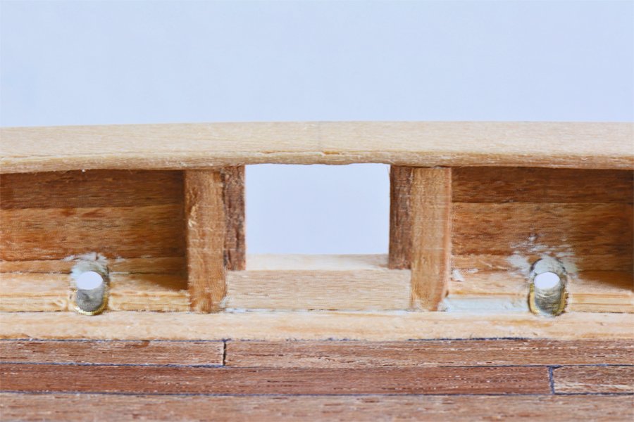
One of the problems you may have is cutting the opening the right size but in the wrong place. If you mark the outline on the hull first and then start cutting, as you get the opening about the right size you will cut away the outline. After it is gone you might end up trimming it a bit too much to one side or the other. Using a jig with a centering mark will help avoid this problem. I carved a tool from a wooden stick, trimming it to the dimensions of the gun port. Wider shoulders on the tool fit against the outside of the planking to limit the extent the tool penetrated into the port. I extended the usefulness of the tool by trimming it further beyond where it penetrated through the hull siding to be used as a guide for positioning the gun port frames and the upper and lower cills to create the rebate for port lids. To help clarify the description, notice that the actual opening in the planking is wider than the opening inside the hull. The rebate that the port lid closes against is formed by frames on either side of the opening and cills at the bottom and top of the opening - but in this case there is no upper cill beneath the top rail. Unfortunately I can't find the tool that I used and I don't have a photo of it. The tool was widest at the shoulders that fit against the outside of the hull planking, then narrower at the dimensions of the port opening in the hull planking, and narrower still at the dimensions of the inside of the port opening between frames and cills. I put a reference mark at the top center of the tool to help position it correctly horizontally. If your gun ports are all positioned vertically the same distance relative to a wale or top rail you can carve the tool to have an edge or shoulder to ride on the wale or rail in order to get the correct height each time. I drew a vertical line on the hull side (the top rail in this case) where the center of the gun port should be, extending above the port. Then I placed the end of the tool against the hull where the port should be and traced the outline on the wood for a guide. This outline was actually smaller than the desired port opening, about the size of the port opening after the frames and cills were added. This left some margin for error. Then I drilled out the center of the port and used files to open the hole and shape it until it was about the size of the outline on the hull. When the opening was about the right size I used the tool to see if it would fit into the opening. Working slowly with files I removed the wood until the stick fit into the opening with a tight slip fit. The center mark on the tool and the vertical line on the hull allowed me to determine which side of the opening to trim. This allowed me to make all of the port openings exactly the same size - the openings in the hull planking and the openings between the frames and cills. You could also use the same tool to help position port hinges by placing reference marks on the shoulder that fits on the outside of the hull planking to be used for marking the positions of the hinges, or even using it as a drilling template.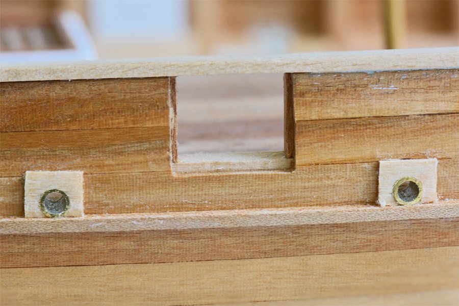
-
Carriage Gun Rigging
Dr PR replied to Dr PR's topic in Discussion for a Ship's Deck Furniture, Guns, boats and other Fittings
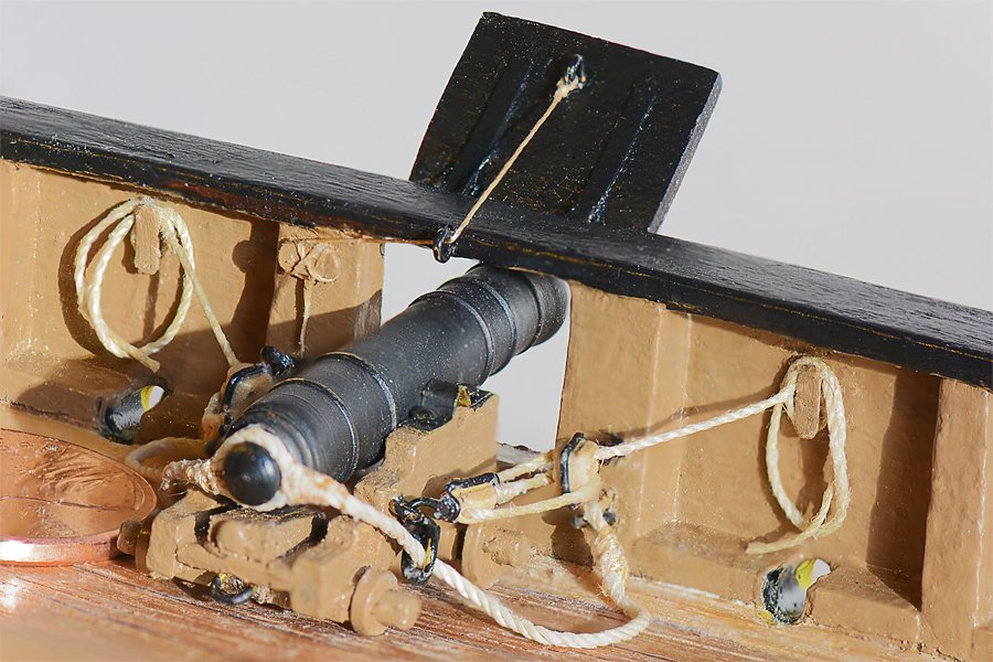
Here is a table of gun rigging data from "The Sea-gunner's Vade-mecum: Being a New Introduction to Practical Gunnery" by Robert Simmons, published in 1812 in England:
-
Breeching ropes were three times the bore length of the cannon, and were about 1/3 the bore diameter, depending upon the size of the gun. You can find a great deal of information about guns and tackle (and a lot more) in this book: http://books.google.co.uk/books?id=aztFAAAAYAAJ&pg=PA1&source=gbs_toc_r&cad=3#v=onepage&q&f=false This is a table from the book: Note: the "size" is the circumference, not the diameter of the rope. (Thanks to xodar461 - Jeff - for pointing this out). If you know the scale of the model (1:64, etc.) and the size of the guns (24 pounder, 6 pounder, etc.) you can calculate the appropriate diameter for the breeching ropes. A 12 pounder at 1:48 scale would have breeching ropes 5 inches circumference, or 5/3.14 = 1.6 inches diameter. At 1:48 scale this is 0.033 inch (0.85 mm) diameter. Another rule of thumb for breeching rope diameter is about 1/3 the gun bore/shot diameter, and this gives dimensions pretty close to those in the table. Gun carriages were generally of a standard design with actual dimensions based upon the shot diameter. Here are some good discussions of cannon rigging:
-
Here are some thoughts on glues: I'm a bit old fashioned - I used Testors "wood glue" for balsa projects when I was a kid. It contained acetone and "smelled like glue." Today I use Duco Cement for wood - it also smells like glue. What I like about it is that it cures in less than a minute when used in small amounts. Usually I can hold parts together for about 20 seconds and they are fastened. But you should allow it to cure for several hours or overnight to get a full bond. It does release acetone so you should use it in a ventilated area, but the amount released is small and I rarely notice it. For bonding wood planking on hulls the best thing I have found is epoxy paints. These are very thin two part epoxy. Airplane modelers use it to cover wooden engine mounts to prevent fuel from soaking into the wood. After the planking is in place (using some other adhesive for a temporary bond to the frames) just paint the inside surface of the hull with the epoxy paint. It will soak into the wood and frames, filling any gaps. I have wooden planked hulls 30 years old and there are no visible cracks between the planks. I like two part epoxies and there are many variations with different cure times. I especially like epoxy putties - some can even be mixed and used under water! When they harden they can be carved and machined like plastics, and they are a great gap filler. Of course the shortcoming is that they must be mixed carefully in the correct proportions (or they will never harden) and you have to mix them just before use. I avoid "super glue" or cyanoacrylate like the plague! I have never had good results, and the stuff usually hardens to a solid before I use it. Back in the '70s the automobile industry started using it to glue rear view mirrors onto the inside if windshields. I had the mirror fall off in a new Camaro. It was reattached with cyanoacrylate several times, and fell off every time. I finally mixed up some epoxy and glued it on myself. That bond lasted for at least 13 years until I sold the car. I later learned why the cyanoacrylate failed on the windshield - dashboard temperatures reached about 90C on very hot days. Cyanoacrylate melts below 100C (boiling temperature of water at atmospheric pressure). We used it to glue together machined parts in specialized microscopes. When we needed to disassemble them we wrapped a heating blanket around the parts and they came apart when the glue melted. CAUTION: cyanoacrylate releases heat (exothermic) as it cures. The greater the amount of glue the hotter it gets. I learned this the hard way many years ago. I used some super glue to glue the frayed ends of pull strings on a sleeping bag, letting it soak into the 1/8 inch diameter cords. Shortly afterwards the cords became very hot and started smoking! I dipped the cords into cold water to prevent a fire. Contrary to what some have said on this forum, cyanoacrylate was not invented to treat wounds in Vietnam! I first saw this stuff in the 1950s, long before Vietnam. But the original stuff was deemed to be too hazardous for the general public because it glued fingers together permanently! So the commercial brands are "watered down" (not actually with water, of course) to make it easier to get glued fingers apart. As others have said there are numerous formulations on the market with numerous variations in properties, so no general statement really applies to all. Ordinary while glue (PVA, polyvinyl acetate, wood glue, Elmers glue, school glue, etc.) is useful with any porous material (wood, cloth, paper, etc.). It is especially useful for bonding knots and ends of ropes and threads. It dries clear and washes off with water. You can soak the material in water to release the bond.
-
Carriage Gun Rigging
Dr PR replied to Dr PR's topic in Discussion for a Ship's Deck Furniture, Guns, boats and other Fittings
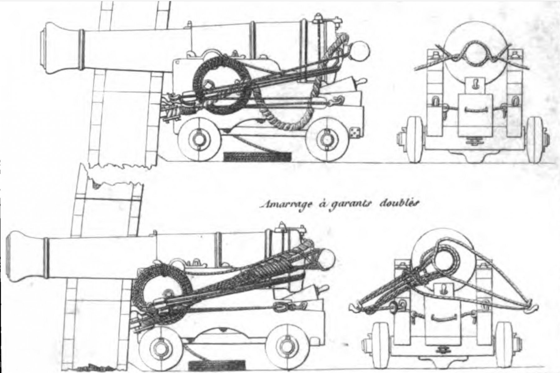
Here is another image showing a way to stow the gun tackle falls when it is not in use. Thanks to archjofo's La Creole post #1386 (an excellent build!): The falls were coiled, bound with small stuff to keep them together, and tied to the gun carriage or placed on the deck beside/below the carriage. One strange thing about this drawing it that it is supposed to be for a French ship, but the breech rope passes through a loop at the cascobel instead of passing through a hole in the carriage as described for Continental ships in several publications. I wonder what period this drawing represents? In my current build I chose to attach the ends of the falls to cleats on the bulwarks. This not only secures the loose ends of the falls, but it also prevents the gun from moving as the ship rolls. Note: THIS IS NOT A FIRING CONFIGURATION. As described earlier, when the gun is hauled out to the firing position the gun tackle falls would be pulled back taut so when the gun recoils the line runs smoothly through the blocks. This would just be a temporary arrangement used after the gun was released from the stowed position but before it was manned for firing. It would be a simple and quick task to release the falls from the cleats. Other than the one drawing (post #1 above) I have seen showing the falls secured to belaying pins on the bulwarks I have no reference for this. It is just a possible solution to securing the gun and the loose ends of the falls. Any thoughts about this?

-
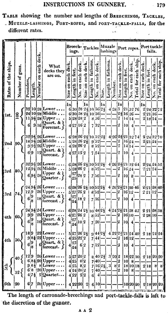
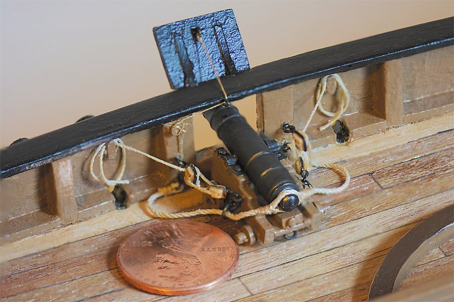
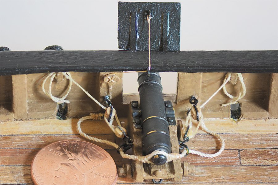
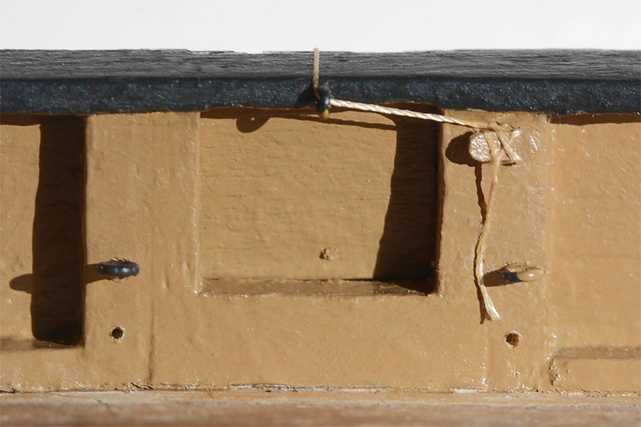
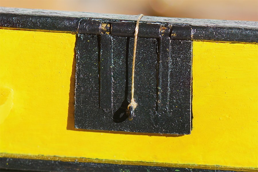
It has been a while since I posted. Most of the delay was spent researching how cannons were rigged in the early to mid 1800s. There are plenty of drawings showing how the gun tackle was rigged when the gun was being fired, and several texts telling how to handle the tackle when firing the guns. There were some drawings and texts telling how to stow the guns - in several different configurations. One text did say that the length of the gun tackle rope should be six times the length of the cannon bore. This would leave several feet of gun tackle falls for the crew to handle when the gun is hauled in until the breech line stops it. But none of these texts or drawings tells what to do with the loose ends of the gun tackle rope when it is not being fired. Many modelers flake these ropes in neat (Flemish) coils on the deck, and some just make loose coils. But this would have never been done at sea - the loose ends would be scattered all over the place and that would be very poor seamanship! Some use the falls to wrap around the tackle as a type of serving. But I could find no text saying this was actually done, at least for a ship at sea. I did find a drawing showing the falls looped around belaying pins (or cleats) on the bulwarks, and another showed the falls looped and tied to prevent the rope from spreading out on the deck. This is what I decided to do - with a US one cent coin for size reference. I placed cleats (Syren Ship Models 3.5 mm boxwood cleats) on the bulwarks to either side of the gun ports. The gun tackle falls were looped around the cleats tightly and then the remainder was draped in a loose coil. I intended to take a turn around the loop with the loose end to create a figure eight (8) coil, but that has turned out to be a test of my dexterity. Maybe I'll do that later, but just accomplishing what you see was a lengthy process! I also intended to wrap the line around the cleat properly, but the cleats are a bit small and the rope would not cooperate. THIS IS NOT INTENDED TO BE A FIRING CONFIGURATION! When the gun was ready for firing the port and starboard tackle crews would pull the gun out to firing position with the gun tackle and then they would stretch the falls out straight so the line would run free. In some cases the lines might be faked down on the deck. When the gun was fired the falls would run through the tackle, acting as a brake for the rearward recoil. This is described in some of the period gun handling texts. But sometime between when the guns were taken from stowage configuration and when they would be fired the guns would be run out and placed in a standby configuration, perhaps as shown here. Because the tall sails could be seen when the ship was far over the horizon, 20 miles or more away (in clear weather), and the ships actually moved slowly at less than 10 knots, it would be hours after a ship was first seen and the guns unstowed until firing commenced. In the mean time some method was needed to restrain the cannons, and tying the gun tackle falls to cleats or belaying pins would provide a means to restrain the guns that could be released quickly. At least that's my theory, and the way it is done on Captain Phil's ship! The gun port lids/covers posed a bit of a problem. As I explained earlier the bulwark height was too low to allow the cannon barrels to run under the cap rail. Even after I designed and scratch built new gun carriages there was little clearance above the barrels. I installed the port hinges in the cap rail edge. Even so, the lids must be raised at a fairly steep angle to allow the cannons to fit under them (as shown above). Raised at such an angle they would provide the gun crew with some protection from musket shot and would be out of the blast from the cannons. After studying books and drawings, and some pictures of actual ships, I came up with this method of raising and securing the lids in position. On larger ships, with heavier lids, the line to the ring bolt on the lid was fed through a two block tackle and then secured to a cleat on the gun port frame or on the bulwark nearby. On this small ship I just used a line without tackle. I led the line through a ring bolt in the cap rail and then to a 3.5 mm cleat beside the gun port. This keeps the line high and clear of the gun. And the thin silk thread could be wrapped properly around the cleat! But, since I made the lids and hinges and installed them I have been thinking that some other arrangement would have been used. Perhaps two lid halves that were hinged vertically to swing to either side would have been more practical. Or the lids might not have been hinged, but were latched in place over the port and removed entirely and stowed when the guns were run out. Maybe the ships didn't have gun port lids! Some of the revenue cutters didn't even have bulwarks. Given the sparsity of information about early 1800s revenue cutters we may never know.
-
Need CAD type program
Dr PR replied to Sambini's topic in CAD and 3D Modelling/Drafting Plans with Software
I would definitely avoid the image editor (pixel) type programs like Photoshop, Paint, etc! Select a cheap/free vector image program. This will allow you to adjust line widths and colors, and scale the drawing easily. They all will output images for printing/plotting at any scale. There are basically two types of vector drawing programs. There are programs designed to make pretty pictures, with a minimum of precision drawing functions. Then there are true CAD (computer aided drafting/design) with a full set of precision drafting tools. If you intend to build a historically accurate model use a CAD program. If you just want to throw something together that "looks like" a ship use a drawing program. -
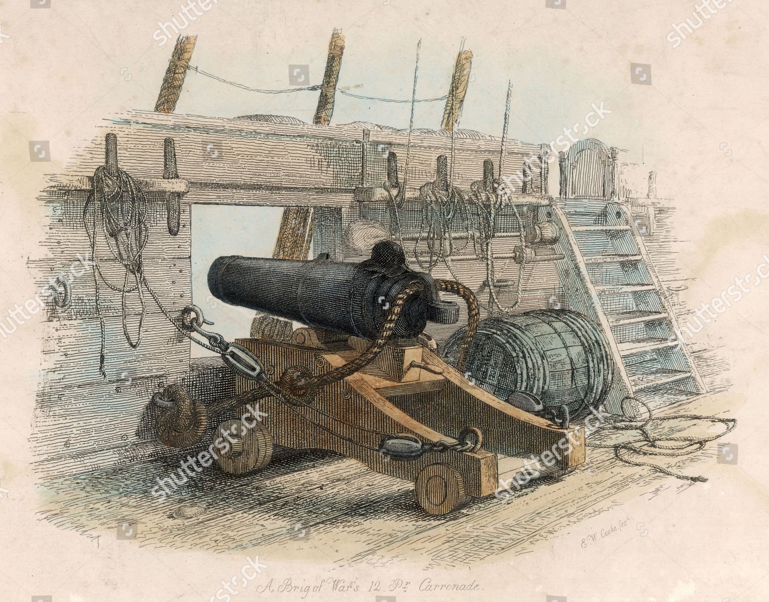
I recently came across a discussion of gun sizes, and one consideration not mentioned so far in this thread was the weight of the guns. The total weight of the guns carried by a ship was limited. In some cases guns were made with short barrels in order to reduce the overall weight of the gun. This allowed more guns to be placed on the ships. This idea eventually led to the invention of the carronade. For a given shot size there was more or less a standard diameter necessary for safe operation of the gun, so weight was reduced by shortening the barrel, not the barrel diameter. Of course, shortening the barrel reduced the effective range, so it was a trade off between effective range and the total throw weight of the broadside. Some ships carried a mixture of short guns and long guns, depending upon what was available, the whim of the Captain, and ship size. I suspect just about any combination you can imagine was afloat somewhere at some time.
-
We are all ignorant of almost everything there is to know - we were born that way. To me "stupid" is the inability to learn, and "dumb" is the refusal to learn. Your are learning so you are neither. I have been building ship models for decades, and I was in the Navy. Even so, I still have problems with a lot of the older terminology - but I am learning!
-
You said you had "Chapelle's book." He has four that discuss revenue cutters and Baltimore clippers, but only the "History of American Sailing Ships" has many plans for revenue cutters. The Bluejacket kit seems to be for the 31 ton design by William Doughty. The "History of the American Sailing Navy" (1985) has drawings of this ship on pages 184, 191 and 196. The drawing on page 191 has the sail plan and spar dimensions. This is the largest drawing of this type I have seen. I suspect the Bluejacket plans are larger than this. Take these sail plans with a grain of salt. There were significant variations from ship to ship, and no one is really sure if any ships were built to Doughty's 31 ton design. Chapelle's "The Baltimore Clipper" is a wealth of information about the general design of the schooners and revenue cutters, but it is a small book with small drawings (and lots of them). It has detailed descriptions of the spars for many of these ships. Note: the original editions of some of Chapelle's books have larger drawings, including many fold out double page size plans. The more recent reprints reduce these plans to a single page. You can find the older editions on Amazon.
- 104 replies
-
- 1
-

-
- revenue cutter
- BlueJacket Shipcrafters
- (and 1 more)
-
Johann, Excellent work! I just discovered this thread this morning, and I have sat here for about 10 hours reading it from start to finish! I have learned a great deal from your work - it is like watching the construction of the real ship. I really appreciate the research you have put into your work! One thing I have been puzzling over is what to do with the loose ends of the gun tackle. I have seen other methods but they didn't seem practical for me, except perhaps when the ship was open for visiting in port and to put on a show. Your method of looping the rope and securing it with small stuff makes sense. This keeps it out of the way but readily available. Another similar method was to loop it over a belaying pin or cleat on the bulwark. I will continue reading your build log with great interest.
-
I would like to add a word of caution about the printable scale idea. Some printers do not print to scale. I had an expensive HP office laser printer that would print a 10.0 inch line from a CAD program as something like 9.94 inches with a 1.0 printing scale in the HP driver. To get it to print the correct length I had to adjust the printing scale to 1.064, and that still wasn't exactly the correct length. It may not sound like much, but 0.06 inch (1.52 mm) is a significant error, and multiple errors can add up to a significant problem. Before you print anything on any printer/plotter where you need a precise dimensions, be sure to test the printer/plotter to see if it actually prints to scale!
-
Thanks.
-
I have a questioning about blackening brass. In many cases I have soldered (tin/lead) brass pieces together and have a bit of visible solder flow at the joints. I use a rotary tool wire brush to remove as much of the solder as possible, and also clean/shine the brass. But the solder (the tin part I think) dissolves into the brass - this is why it makes a strong bond. No amount of polishing short of grinding away the brass will remove the solder "stain." Do any of the blackening agents also blacken the solder, or do they just blacken the brass and leave the shiny solder stain? Phil
-
VTH, This is where a build can get interesting. The actual plank length depended upon the supply of timber when the ship was built. If the trees were tall the planks could be very long. About the only thing you can say for sure about deck plank lengths is that it will be multiples of the spacing of the deck beams. But what is the deck beam spacing? Is it shown on the kit plans? If not you have some research to do. Deck beam spacing is typically the same as or a multiple of the hull frame spacing (not the model bulkhead spacing). How long is the model supposed to be in scale feet (the kit description says 30 to 36 feet)? You can look for other models or drawings of schooners of about the same length and see what was used on them. The scale is 3/8 inch per foot, or 1:32. Overall length of the model is 17 inches, or 45.3 scale feet. So look for plans or drawings for a schooner with a hull of about 36 feet and overall length of about 45 feet.
- 90 replies
-
- 3
-
-
- finished
- Midwest Products
- (and 1 more)
-
Carriage Gun Rigging
Dr PR replied to Dr PR's topic in Discussion for a Ship's Deck Furniture, Guns, boats and other Fittings
Kieth, I also notice the wheel chocks. Some were used when the cannon was secured for stowage, and others were used during loading to prevent the gun from moving. In the drawing of the stowed gun it appears to me that the training tackle was hooked to a rope that was looped around the cascobel and the other end was hooked to a ring bolt on the bulwark above the gun. Then the tackle was pulled tight to push the gun against the bulwark. The gun tackles and breeching ropes were siezed to take up slack and hold the gun in place. But I have seen other drawings showing different methods of securing the gun. My guess is that it might have been done differently on each ship, depending upon the type of gun, configuration of the gun port and bulwark (if any) and other features peculiar to the ship and crew. When I was in the Navy the ships changed all the time, especially the small details. If the Ship's Bosun decided he needed another cleat or eye he called the engineers and they brought up a torch and added the new piece. In the yards a five pound tin of coffee could buy quite a few unauthorized things! On the old wooden ships you only needed to ask the carpenter. And the Captains had a habit of customizing the configuration of major things like masts and spars to suit their whims. If it isn't too absurd, just about anything you can model has a chance of being "prototypical." -
Carriage Gun Rigging
Dr PR replied to Dr PR's topic in Discussion for a Ship's Deck Furniture, Guns, boats and other Fittings
Thanks to everyone for the comments. I also thought closing the gun ports between shots seemed a bit strange, although the desire to be protected from musket fire and grape shot while the gun was being loaded was obvious. There is even a caution that the men should avoid exposing themselves through the gun port. With a clearance behind the bulwarks to the gun muzzle of only about a foot there wouldn't be room for a typical worm, swab and rammer. As I understood it the men would poke the handles out the gun port to get these long pieces into the barrel. However, I have seen several references, and even videos of modern reenactments, where the sponge/swab was a flexible bunch of rags and ropes that could be bent around and into the barrel. Also, some gun port covers had holes called "ventilation scuttles" (Mondfeld's Historic Ship Models page 177) and I had wondered if the handles were pushed out through these? Maybe these holes are the "port scuttle" mentioned in the Ordnance Instructions? Mark is correct about checking the period and type of ship and guns. There was a lot of variation between ship types and periods, so whatever we model must fit these requirements. But until someone invents a time machine we won't know how things were really done way back when! -
I have been wondering the same thing. Beef wellington (Jason) said this is what he uses: "The fine thread is UNI-Thread W 6/0 Tan - not sure what that means, but that's what's on the reel! Nothing fancy, think I picked it up at a local craft store some time ago, its synthetic so need to use GS-Hypo cement rather than PVA if it needs to be secured." I would think the caution about the glue would also apply to fishing line. The GS-Hypo cement is something jewelers have used since the 1930s. It is supposed to not harden and remain flexible. I haven't used it myself but I will look for it at the local crafts store.
-
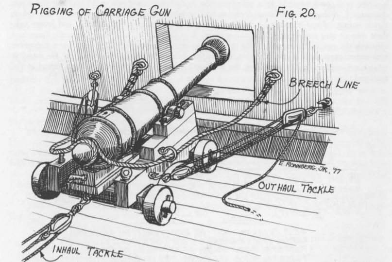
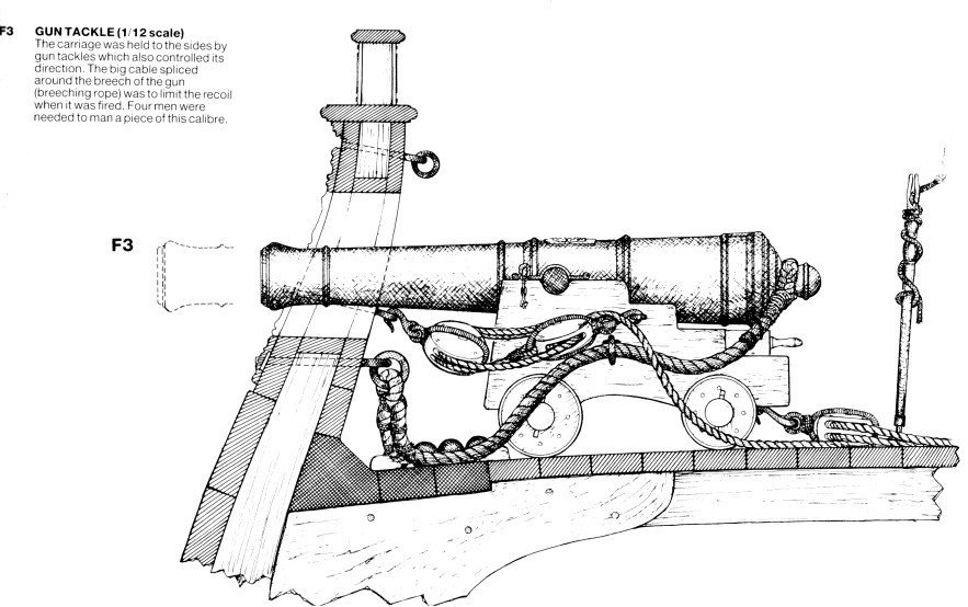
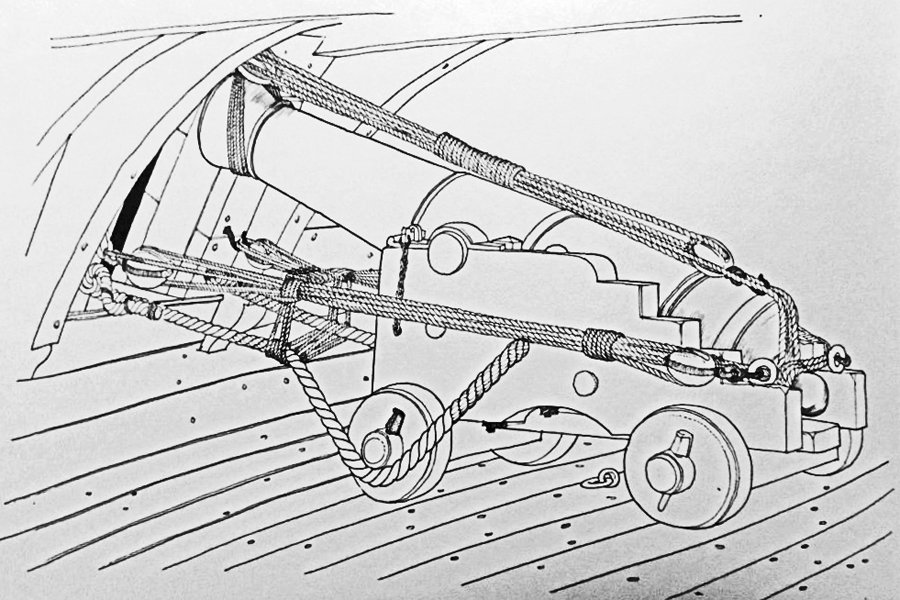
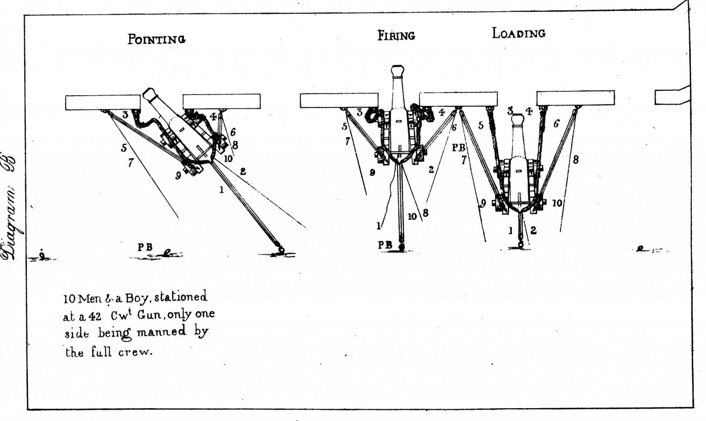
This is a rehash of much I have found on the forum and possibly some new information. I have seen discussion of how to model the rigging of carriage guns, with lots of speculation. I hope to condense this a bit here. Here are some drawings of British and American gun tackle and breeching lines. The breeching lines are attached to ring bolts on the bulwarks and are attached to the cascobels at the rear of the cannon. In some cases they are wrapped around the cascobel as shown at the left. Sometimes they were attached with a cut splice that fit around the cascobel, as shown at the right. Later guns had a breeching ring cast into the barrel above the cascobel, and the breecing line passed through it. The breeching line stopped the recoil of the gun when it was fired, preventing it from crashing about the deck. It was roughly 1/3 the diameter of the shot, and was long enough (3 times the length of the cannon bore) to allow the cannon to move about a foot or two inboard of the bulwark to give the gun crew room to swab and load the cannon. There were very specific methods of attaching the breeching lines to the bulwark ring bolts, normally using seizing of small line wrapped around the breeching line. The gun tackle (outhaul tackle) hooked to a ring bolt on the bulwark, and hooked to a ring bolt on the gun carriage. The gun tackle was used to haul the gun out to the battery (firing) position after it was loaded. This tackle for larger guns consisted of a single block hooked to the gun carriage and a double block hooked to the bulwark. Smaller guns might just use two single blocks. A "loose end" (pun intended) in the descriptions of the gun tackle is what to do with the falls (loose ends) of the tackle? The line leading from the block attached to the bulwark had to be long enough for the gun crew to grab. Then when the gun was hauled to battery and the blocks came together, more line, 3-4 times the longest distance between the blocks when the gun was in the loading position, was pulled out of the tackle - that is a lot of line. Typically drawings just show the falls going off somewhere. What did they do with all of that line? I have seen four variations for dealing with the gun tackle falls. The picture on the left above shows the loose ends "frapped" (wrapped) around the tackle. However, most of the falls was taken up by looping it a few times through the rings on the hooks at the bulwark and gun carriage, with the remaining part frapped around the bundle of lines. This would have been used to secure the guns when they weren't being used, in port or at sea. Note the breeching loop cast into the rear of the cannon. The picture right above shows the end of the falls "Flemished" in a tight spiral on the deck. Many models use this method because it is a simple way to deal with the loose ends. However, on real ships this was done for show only, during inspections or ship visiting days. There is no way this would have been used at sea! The loose ropes would be scattered all over the deck, and this was not good! Another way to secure the gun tackle loose ends that I have seen was to belay the line around cleats or belaying pins on the bulwarks. This would be a "ready stowage" solution to keep the ropes from flopping around the decks and getting tangled while approaching a battle. But it could also be used when the guns were secured. Another method was to just roll the line into a lose coil and place it on the deck near the bulwark block. Again, this would have been a temporary stowage while preparing for battle. In battle the falls would have been pulled taut straight back from the block along side the cannon by the side tacklemen, and perhaps faked down on deck for long falls. When the gun was fired the line ran cleanly through the block - the tackle absorbed some of the recoil momentum. Note: Not everyone is happy with this explanation - see the references below to support my reasoning. **** The training tackle (inhaul tackle) was similar to the gun tackle. It hooked to a ring bolt at the rear of the gun carriage and to another ring bolt mounted in the deck some distance behind the gun. The training tackle was used to haul the gun back inboard to the loading position. Some ships used a single training tackle, others used two training tackles (only the heaviest guns >= 36 pounders had two training tackles), and you often see pictures and drawings where no training tackle is used. What did they do with the training tackle when it wasn't being used? Apparently it was stowed with all the other gun handling gear, often on the bulwarks between the guns, at least while they were preparing for battle. When the guns were secured all the loose paraphernalia was probably stowed below. This drawing shows a Continental (French, Dutch, etc.) style gun. First note that the breeching line passes through a hole in the gun carriage, and it does not attach to the cannon. It serves the same function, to stop the recoil, and it must be long enough to allow the gun to move inboard at least 1/3 meter for loading. The drawing shows the gun in a stowed position with the end of the barrel raised (with the quoin removed) and pulled tightly against the top of the inside of the gun port. This was common in all navies, but there were probably as many variations as there were ships. The tackle was used to draw the gun tight against the bulwark, and lines were frapped to take up slack. Chocks were also used to secure the gun. The last thing you wanted was a loose cannon rolling around the decks in heavy seas! The answers to many of these questions are found in Ordnance Instructions for the Unites States Navy (1860) which can be downloaded here: https://archive.org/details/ordnanceinstruc00ordngoog Gun and train tackles were not removed before the gun was fired (pages 45 -47)! Up to the Ready/Fire commands the side tacklemen held the falls taut. At the command "fire!" side tacklemen dropped the tackle and falls and let them run to slow the recoil. The train tacklemen pulled on the falls to take up the slack as the gun recoiled, and then held the gun until it was loaded. However, the train tackle could be unhooked before firing in calm seas and then attached after recoil. Note: The text describes when the gun tackles are hooked to the bulkheads and to the rings on the gun carriage, and which of the gun crew does each task. It never mentions unhooking the gun tackle until the gun is to be secured and stowed. In the drawing below the gun tackles and training tackles are attached in the firing position. The gun was pointed by hauling it in to the extent allowed by the breeching line, and then one or the other side tackle was hauled in to swing the gun left or right (page 46). Here is a diagram showing pointing, firing and loading: Breeching must be long enough to allow the gun to clear the gun port at least one foot when hauled fully inboard. Neither breeching nor tackle can be blackened or treated in any other way that reduces flexibility. They are to be made of manila or another pliable rope. (page 150). I haven't read it all, but I couldn't find any description of how the gun tackle falls were to be secured/stowed when not in use. However, at the command "cast loose" the tackles were to be removed from stowage and then hooked to the bulwark and gun carriage. So maybe they were not hooked to the guns while they were stowed? Or were the frapped tackle considered "stowed?" **** As far as placement of the ring bolts for the gun tackle on the bulwarks, the diagram above shows the attachment points spaced far from the gun port to allow a significant angle of pull on the tackle for pointing the gun. But most photos and drawings do not show them as widely spaced as in the drawing above. I have also see (somewhere) a drawing showing double ring bolts for the train tackle on the bulwarks, on each side of the gun port, spaced fairly close together, in case one bolt fails. In the description of how to point the gun it says the gunners used the handspikes to lever the gun left/right to assist the tackle. So it wasn't necessary for the gun tackles to be spaced widely as shown in the diagram above. The tackle could be used to hold and fine tune the point. The handspikes were also used to raise the breech to free the quoin so it could be repositiond to change the gun elevation. One other detail I had been wondering about - the port tackle (for the gun port lid) was secured to a cleat on the inner top of the gun port. The door/lid was to be raised high to prevent damage from the blast of the gun. After each shot the port lids might be closed to provide protection for the gun crews while they were reloading. **** There is a lot of useful information in this document. It was written in 1855 and amended in 1860, but gunnery practices probably had not changed much in centuries except as new gun types were introduced. The referenced text describes practices for smooth bore muzzle loading guns. **** I hope this is helpful, and that it will stimulate further discussion.

- 38 replies
-
- 20
-
-
Jason, Will do. I was worried that we were hijacking your thread. When I get time I will post a condensation of these discussions in the deck furniture, boats, guns and other fittings section.
-
The answers to many of our questions are found in Ordnance Instructions for the Unites States Navy (1860) which can be downloaded here: https://archive.org/details/ordnanceinstruc00ordngoog First of all, gun and train tackles were not removed before the gun was fired (pages 45 -47)! Up to the Ready/Fire commands the side tacklemen held the falls taut. At the command "fire!" side tacklemen dropped the tackle and falls and let them run to slow the recoil. The train tacklemen pulled on the falls to take up the slack as the gun recoiled, and then held the gun until it was loaded. However, the train tackle could be unhooked before firing in calm seas and then attached after recoil. Note: The text describes when the gun tackles are hooked to the bulkheads and to the rings on the gun carriage, and which of the gun crew does each task. It never mentions unhooking the gun tackle until the gun is to be secured and stowed. The gun was pointed by hauling it in to the extent allowed by the breeching line, and then one or the other side tackle was hauled in to swing the gun left or right (page 46). Here is a diagram showing pointing, firing and loading: Breeching must be long enough to allow the gun to clear the gun port at least one foot when hauled fully inboard. Neither breeching nor tackle can be blackened or treated in any other way that reduces flexibility. They are to be made of manila or another pliable rope. (page 150). I haven't read it all, but I couldn't find any description of how the gun tackle falls were to be secured/stowed when not in use. However, at the command "cast loose" the tackles were to be removed from stowage and then hooked to the bulwark and gun carriage. So apparently they were not hooked to the guns while they were stowed. **** As far as placement of the ring bolts for the gun tackle on the bulwarks, the diagram above shows the attachment points spaced far from the gun port to allow a significant angle of pull on the tackle for pointing the gun. But most photos and drawings do not show them as widely spaced as in the drawing above. I have also see (somewhere) a drawing showing double ring bolts for the train tackle on the bulwarks, on each side of the gun port, spaced fairly close together, in case one bolt fails. In the description of how to point the gun it says the gunners used the handspikes to lever the gun left/right to assist the tackle. So it wasn't necessary for the gun tackles to be spaced widely as shown in the diagram above. The tackle could be used to hold and fine tune the point. The handspikes were also used to raise the breech to free the quoin so it could be repositiond to change the gun elevation. One other detail I had been wondering about - the port tackle (for the gun port lid) was secured to a cleat on the inner top of the gun port. The door/lid was to be raised high to prevent damage from the blast of the gun. After each shot the port lids were closed to provide protection for the gun crews while they were reloading. **** There is a lot of useful information in this document. It was written in 1855 and amended in 1860, but gunnery practices probably had not changed much in centuries except as new gun types were introduced. The referenced text describes practices for smooth bore muzzle loading guns.

-
Jason, Thanks for the information. Your 1:64 build is very clean and neat! Much more so than my 1:48, so I was wondering how you do it. But I think I understand now. The Diana/Jason was 121 feet on the keel and 146 feet overall. My Baltimore clipper was 68 feet between perps. Your model will be about 22 inches on the keel while mine is about 17 inches, so yours is about 1/3 larger. I would expect the larger scale model to be neater than a smaller scale just because wood grain, loose thread fibers, dust etc. would be smaller relative to the model. However, your model appears to have less of those details and fewer visible imperfections in the photos - especially the guns. I am envious! However, I am modeling 6 pounder cannons at 1:48 and you are modelling much larger 18 pounder guns at 1:64, so your model cannon and carriages are about 1.75 times as large as mine! In the close up photos my imperfections and dust get 3-4 times as many pixels - and I am using one of the best macro lenses made (Nikon 105 mm macro) that makes very sharp pictures of the imperfections! Now I think my work isn't quite as crude as I thought compared to yours. Because of some peculiarities of the kit I am building (and my kitbash) I had to make the gun carriages from scratch. I think they look OK, but for future builds I will try to use Chuck's gun carriages. They are very clean. I am using the Syren 3/32 blocks for the gun tackle, and they are very small! As you said, these blighters take time!
-
Bob, Good photos. They show the frapping well. I agree that it would make sense to unhook the tackle, at least from the gun carriage, before firing the gun. There is too much chance that the fall will be tangled and jam in the block. With a single/double block tackle there are four lines running between the blocks. So for every foot of gun recoil four feet of the fall would be drawn into the blocks. The rope would be whizzing through the tackle very fast. I don't think that could be managed to avoid tangles very easily, but experienced gunners might have had a way to do it. However, I have seen other discussions on this forum saying that the tackle was attached and acted as a shock absorber as the lines ran through it. I have also read that the hooks were moused. But that is all speculation. I would also guess that the gun tackle was also used as training tackle, since both would not normally be in use at the same time. Just unhook it from one position and move it to the other. In this case the hooks certainly would not be moused! The drawings I have seen show both the breeching line and the gun tackles fastened to ring bolts that penetrated through the timbers and planking to fasteners on the outside of the hull. If these could take the shock of the breeching line they would also be able to withstand the lesser shock of a gun tackle slowing the recoil. Somewhere here I read a post that quoted from a 19th century gunnery manual, but I don't remember who had it. That might answer the questions. I have looked through several books that I have for rigging sailing ships but they don't mention the guns. Note in your first picture that there are belaying pin rails to either side of the gun where the falls could be belayed when the gun was not in use. But they would not necessarily be used. Again, speculation. Also notice that the fall was looped through the eyes of the hooks at least twice before the frapping was wound. This took up most of the falls and only the free end was used for frapping. So the part of the line that passes through the blocks would not be wound in the frapping. Have we hijacked Jason's thread? Should this discussion be elsewhere?
-
I have been wondering what to do with the falls from the gun tackle. I have seen four methods - so far. 1. Flemish coils on the deck. I have seen the ends of ropes Flemished on some of the ships I have served on, but only for show when we were having an inspection or open ship (visiting ship). There is no way this method would have been used at sea! The unsecured ropes would soon be scattered all over the deck. 2. Frapping similar to what Jason has done. However, the fall (the part pulled upon) is usually fairly long and is often looped around the hooks at either end of the tackle before the remaining line is frapped around the rest between the blocks. This would be done when the guns were stowed in port and possibly when at sea with no probability of using the guns. 3. I have seen drawings showing guns run out and ready for action with the falls loosely coiled (not Flemished) on the deck near the double block by the bulwark. This would position the rope out of the way of the crew and ready to run through the blocks as the gun recoiled. The coil would have to be arranged carefully to avoid tangled loops that would hang up on the blocks. Maybe the line would be uncoiled and pulled taut just before the gun was fired to ensure it would run free without tangles. 4. A fourth method that would be used when the guns were run out, but not to be fired immediately, was to loop the rope over a cleat or belaying pin on the bulwark near the double block. This would keep the line off the deck and in a known untangled state that could be prepared for firing quickly. I suspect this method would be used when there was a potential for action but the ship was not at quarters (Condition 1 or General Quarters) - what we called "Condition 2" when I was in the Navy. I have seen only one drawing showing this, and I don't recall seeing it on a model. I am considering either method 2 or 4 for my current model. Remember that sailing ships moved very slowly - even the fastest clippers went only about 16 knots average. Sails on tall ships would be visible at a distance of 20 miles or better (up to 40 miles from the tops) and it would take quite a while for the ships to come into gun range after they spotted the enemy. Even if both ships sailed toward each other, at 6-8 knots it would take hours to close within smooth bore gun range. That would be plenty of time to prepare and run out the guns.
-
Jason, I just came across your build. Very impressive!! What size Syren blocks did you use for the gun tackle? Your work is very neat. I have been trying to decide what to do with the falls (loose ends) of the gun tackle. Your example of frapping is interesting. The Syren gun carriages are very neat. You may have stated this earlier, and I missed it, but what finish did you use for the red color? One last question (for now). What did you use for the very thin thread seizing around the splices in post #614??