


realworkingsailor
-
Posts
3,091 -
Joined
-
Last visited
Content Type
Profiles
Forums
Gallery
Events
Posts posted by realworkingsailor
-
-
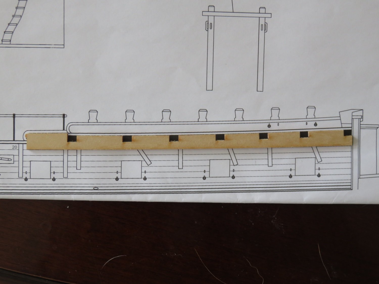
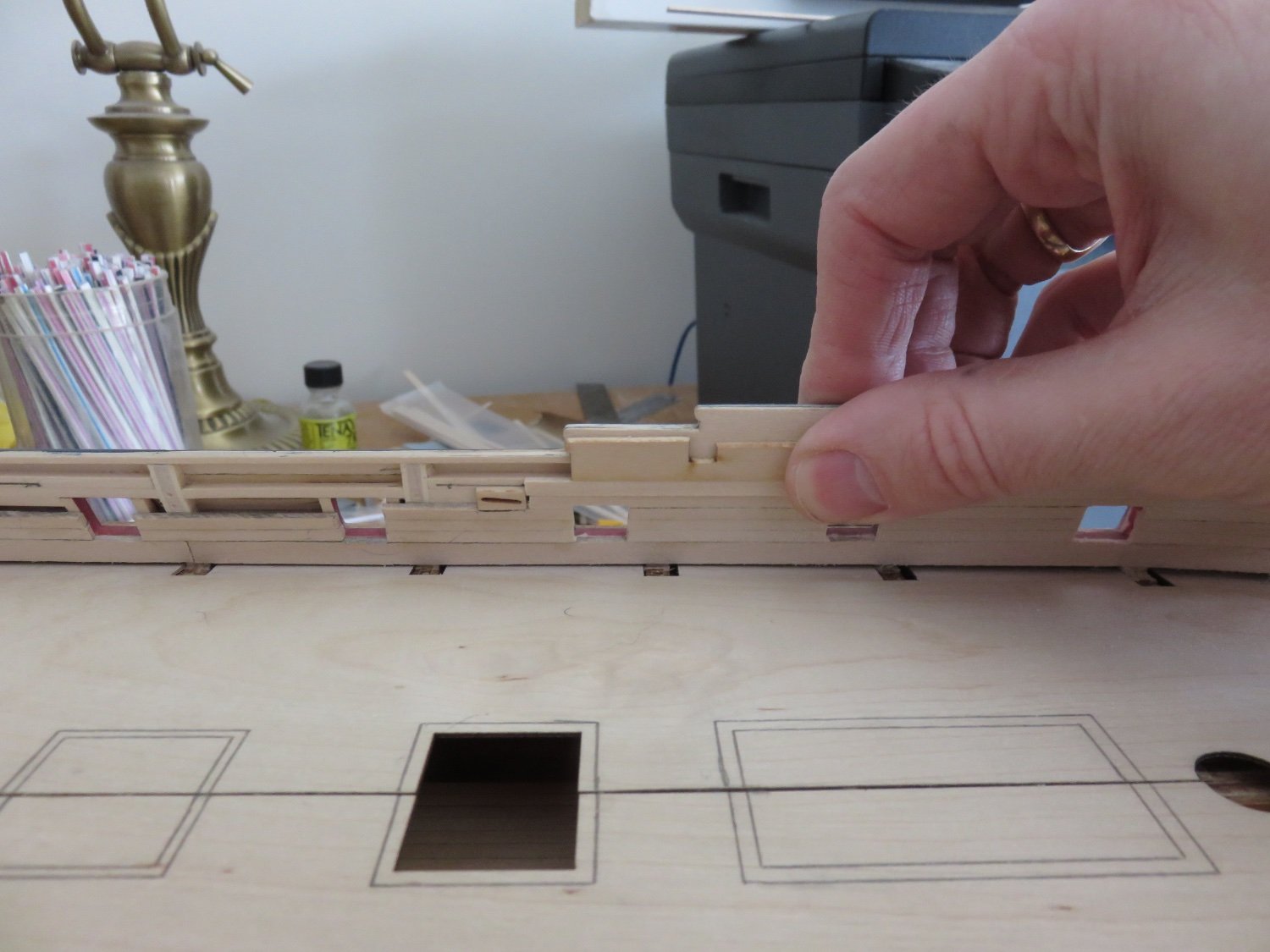
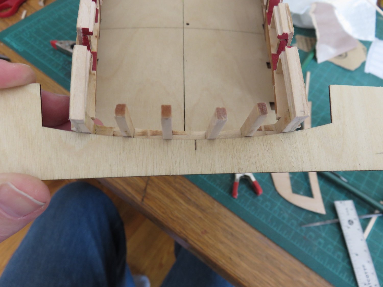
I think this helps to illustrate my point in the above post:
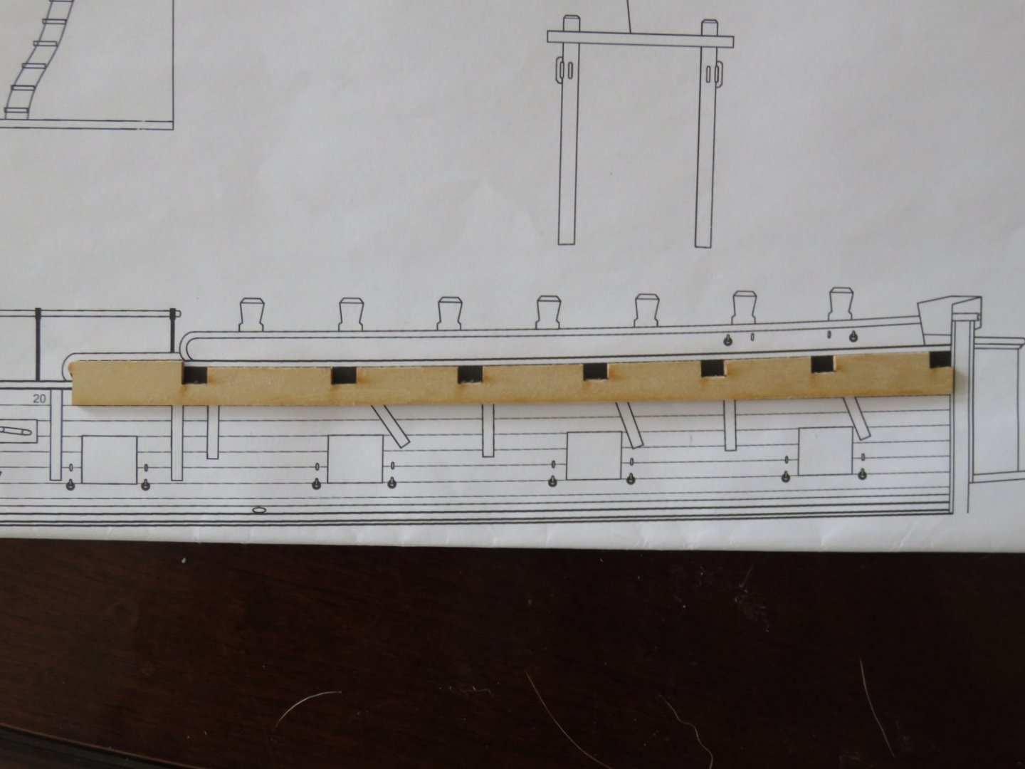
Taken from the elevation view, you can see the laser cut clamp matches the drawing virtually spot on.
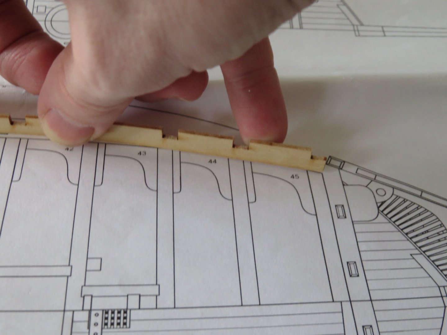
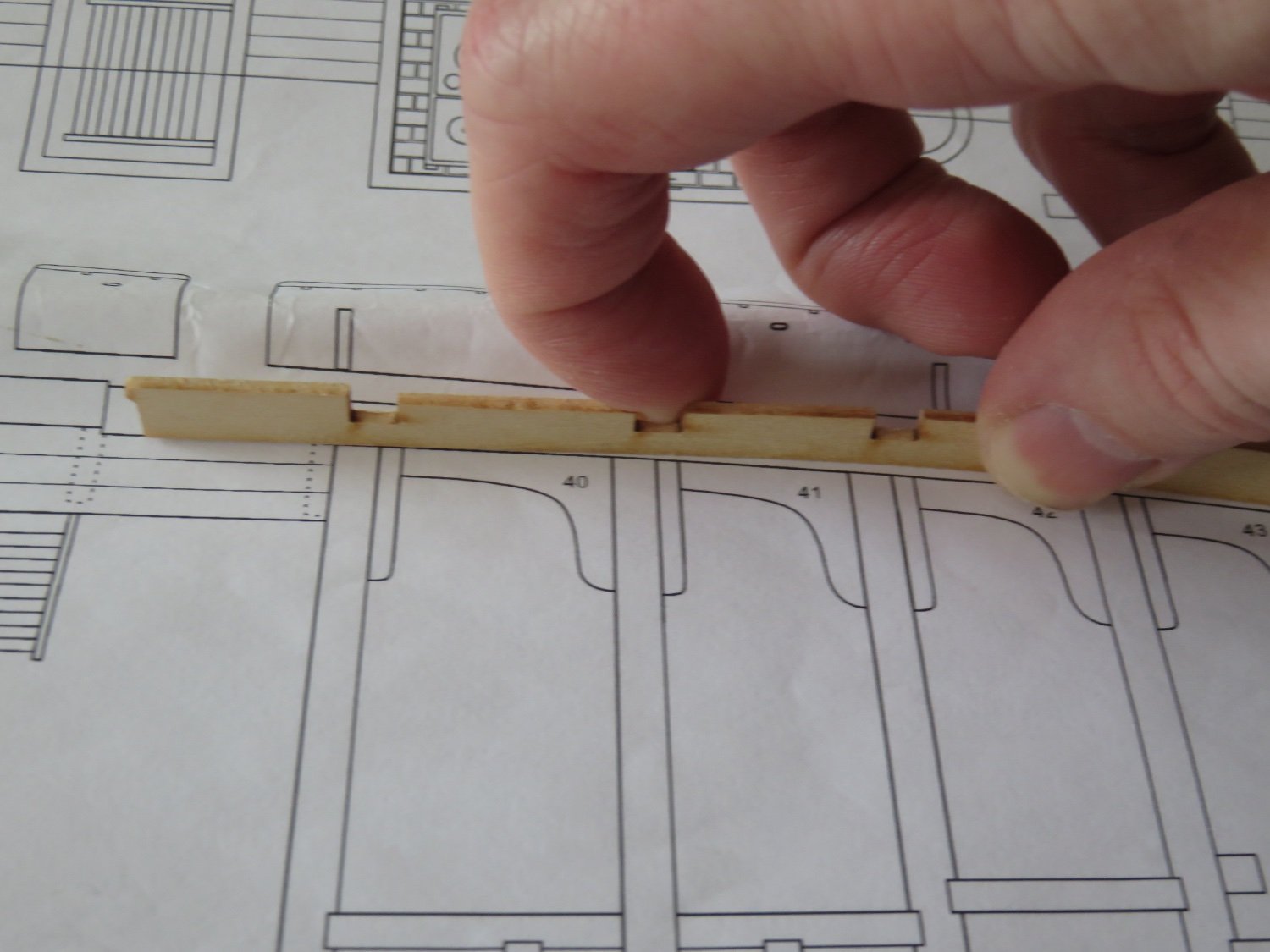
(Please forgive my fingers, but here in the plan view, you can see how quickly the curve begins to throw everything out of alignment after the first beam, with an increasing amount as you go aft, to this point:

Of course, as the curve decreases, the error between beams equalizes, but compare the error between the second beam and the last (which is well over 1/16").
Methinks I needs to gets me some 1/16" basswood sheet and remake the clamps from scratch....
Andy
- JohnB40, WalrusGuy, Paul Le Wol and 4 others
-
 7
7
-
2 minutes ago, WalrusGuy said:
As for the fo'c'sle clamp, have you thought about the option to glue in an extra scrap piece of wood fore of the clamp so that the aft end matches? Filler could be used to hide the seams between the extra wood and the supplied cutout. I'm eager to hear what others also think about how to solve this.
I did think of that, but I’m not sure how that would play out when positioning the deck details later on. Hatches, and other openings), bits as well as the foremast could be drastically affected by the resulting repositioning of the deck beams.
I was just going over the plans, and it seems to be an error of projection. The laser cut clamp matches the 2D elevation view, but it doesn’t take in to account the curve of the bow.
Which means the clamp would have to be cut into multiple segments and stretched proportionally to the amount of curvature.
Andy
-
Something is not right.
I am running into a couple of errors. I'm fairly sure the errors are not mine, I think.
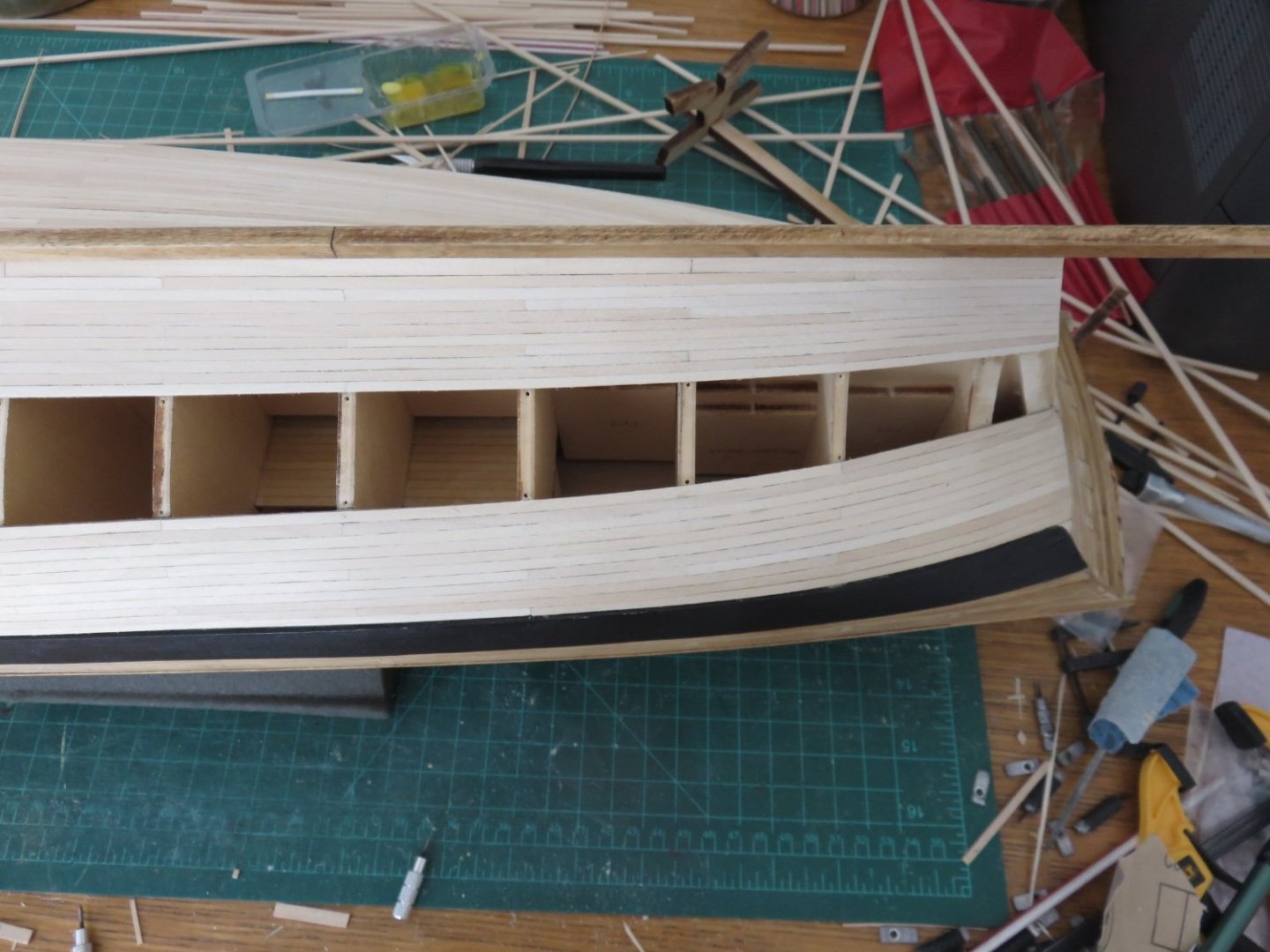
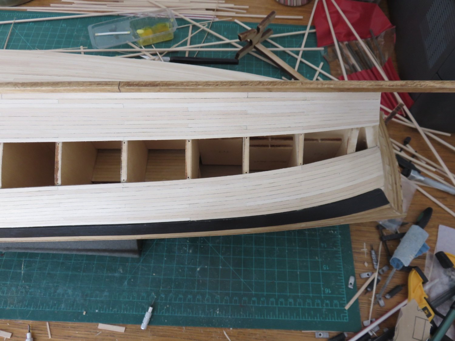
As I made mention before, I have decided to begin planking the bulwarks. Things got off to an ok start. The 1/4" spirketing strip lined up with the gunport cills as described in the text. Big sigh of relief, that part worked. Starting from the bow, I began adding the 1/8" strips building up around the gunports. Tedious, but not challenging.
When I had added the first four strakes as far back as the hull sheave, I thought it would be a good idea to follow up with the instructions and do a little pre-test to ensure that the fo'c'sle clamp would line up. That's when progress went sproing....

Following the instructions, I placed the fifth 1/8" strip on and then the fo'c'sle clamp. As you can see from the above photo, it's low. one sixteenth of an inch low, to be precise. Checking a little further along in the waist, everything is going to be 1/16" too low.
Then the gears started turning. Not long ago then I made the QG stools, in order to line up with the transom, I had to mount them even with the bottom of the QG opening, counter to the instructions which say they need to be 1/16" below:
This is why I have doubts that the error is solely my own. I know I took great pains to ensure that the gunport framing, the positions of the wales and the run of the planking matched as closely as possible, the laser etched marks on the bulkhead. There is far too much consistency in this error for it to be the product of sloppy building. There is no way that I missed the entirety of the outer planking, wales etc, by 1/16", as well as the run of the gunports, and now the internal planking by 1/16". Consistently. And based on preliminary observations, on both sides as well. Equally.
I don't think this error is insurmountable, as far as the fix. It's simply a matter of using a 3/16" strip in place of the 1/8" strip, and then hoping that there's no other trap further down the line.
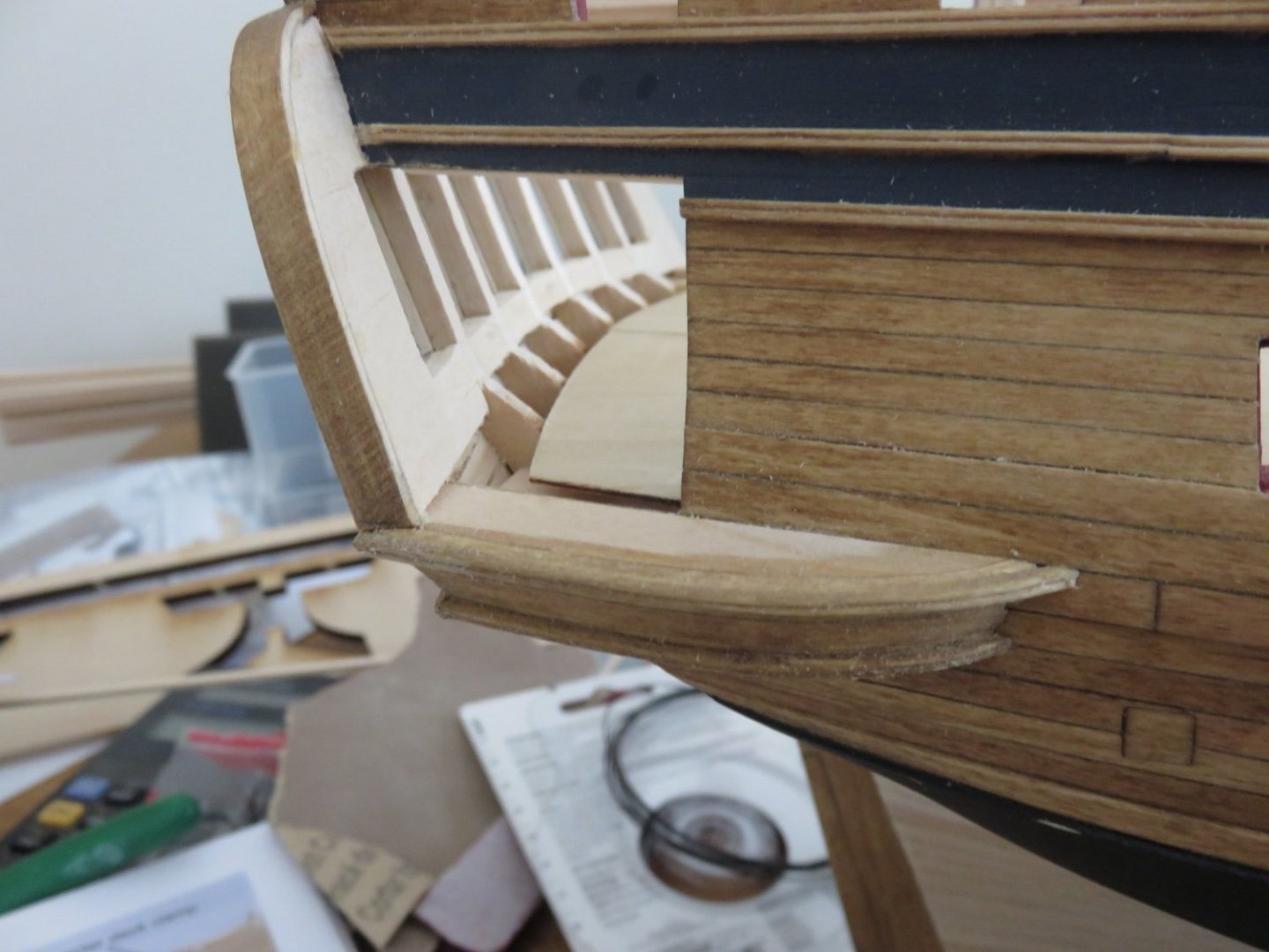
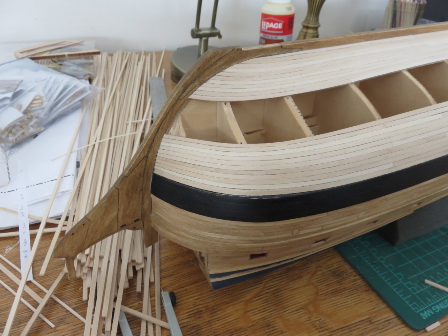
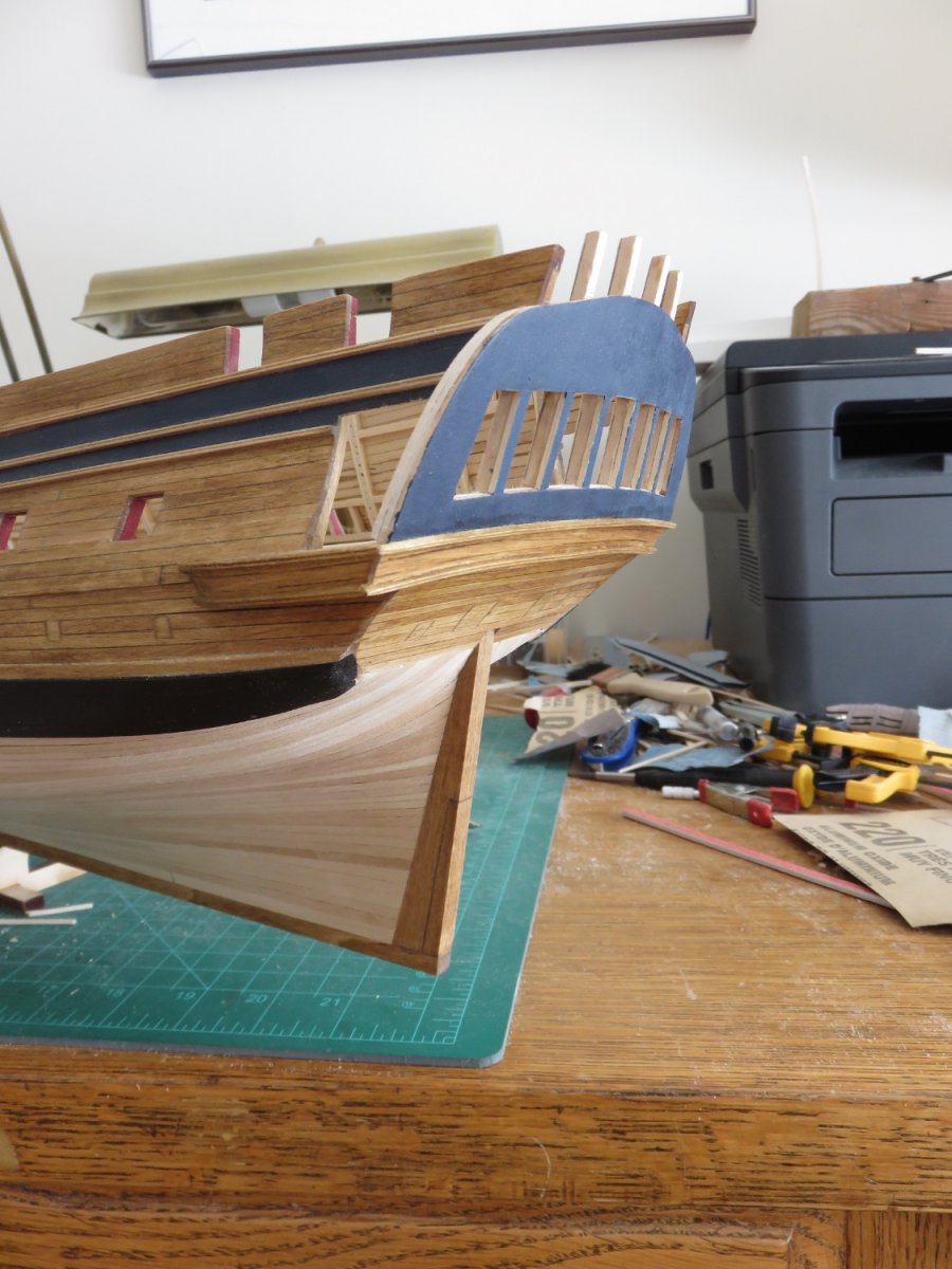
The second error I have run into, is the fo'c'sle clamp is too short:
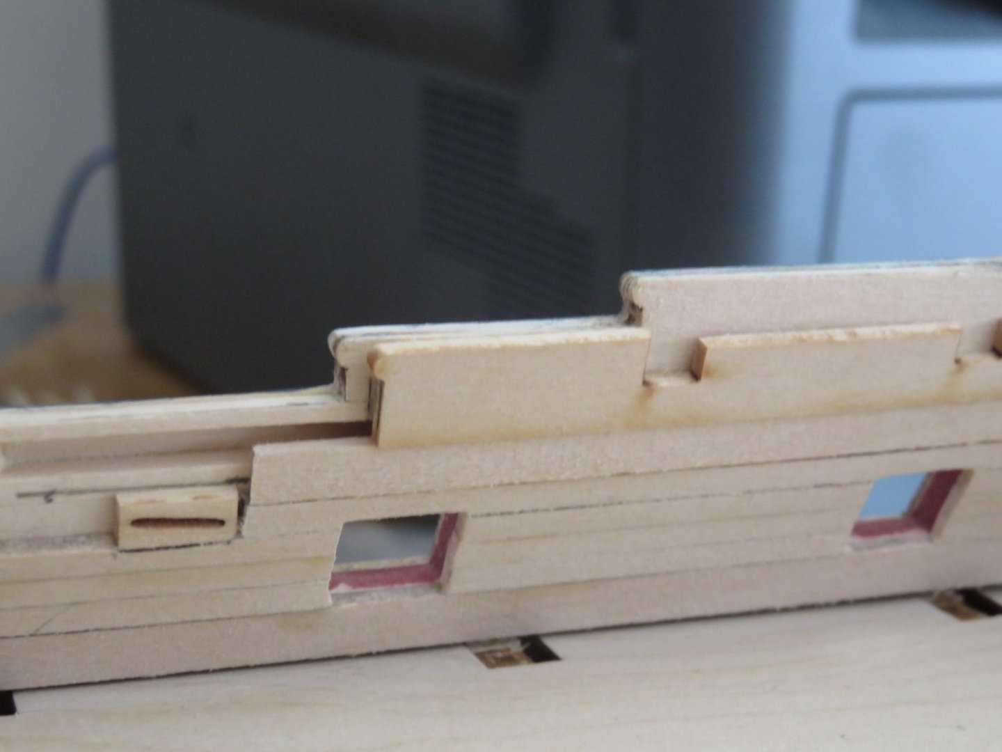
Or the hanse piece is too long, or the bulkhead just ahead of the hanse piece is in completely the wrong position. In the above photo you can see that using a 3/16" strip brings the clamp to the correct height, but with the forward end butted up to the beak head bulkhead (although not yet beveled to mate flush), it's short. I'm still forming a plan to tackle this issue as well.
There are two approaches (I think): (a)gingerly remove the hanse piece without destroying the outer planking, sand the forward end to match the aft end with the clamp, replace and sand down the planking to match or (b) use some of the spare leftover pieces (for some reason there where hanse pieces in both basswood and ply included in my kit) as a template to mark the new aft end and then sand the aft end to the marks.
(BTW, that janky looking plank end by the hull sheave will be fixed before painting. Closeup photography does no one any favours 🙄)
Again, I'm not sure where the error comes from, as there also seems to be the same issue with the other side. The bulkhead is as close to square as I could get it, and the error seems to be consistent from port to starboard.
Sigh.
Suggestions, comments, observations always welcome.
Andy
-
-
-
Forward some more!
The sanding went better than I expected, but still a drawn out process. There remains only a bit of final touch up here and there, but otherwise the inboard framing has been sanded down to its prescribed thickness.
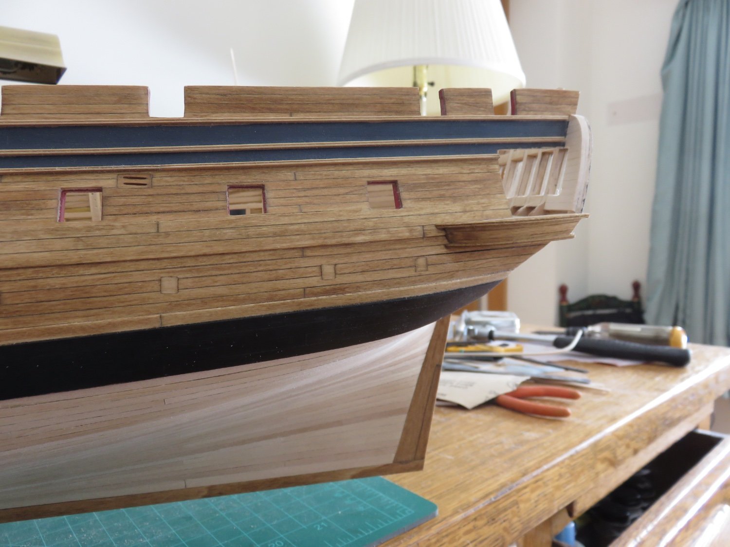
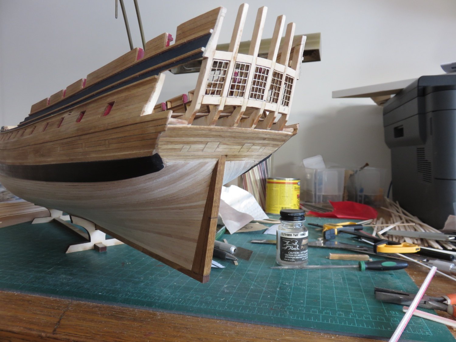
I have taken a break from sanding to work a little more on the stern trim pieces. I am leaning towards keeping the upper counter unpainted, and probably most of the QGs as well.
I did paint the transom the same dark blue I used on the upper works. A little sanding and another coat of paint still to go, but I'm happy with the colour.


I have now come to a bit of a crossroads. I am wondering about skipping ahead a little and doing the inboard planking now, while I still have open access through the QG openings (to sand the plank ends cleanly). Comments or suggestions are welcome.
Andy
-
On 2/19/2022 at 1:39 PM, JKC27 said:

I was just looking through your build photos again, and noticed that your forward fairleads don’t line up with the winches. That poor mate is going to get a royal blast from the old man for breaking so many wires on the hatch coaming!🤪
(The winches should also be staggered fwd and aft in the hatch bay so their wires run clear to both sides).
Otherwise, it’s looking great 👍
Andy
-
Thanks everyone for the "likes".
A small update, this time movement has only been in a forward direction!
I have made up and planked the quarter gallery stools (both port and starboard):

I've also made up the moulded trim, but I've decided against affixing it for the moment. I will eventually stain the QG stools and trim. I have not yet decided how I will finish them, colour wise, I think I will keep my options open for now.
I've also begun tackling the laborious task of thinning and fairing down the inside of the bulwarks (does Chuck own shares in a sandpaper manufacturing company? 😜). Anyway, a necessary exertion.
At some point in time during yesterday afternoon's sanding session (it's all a bit of a dusty blur at the moment), it occurred to me that this is going to be a multi session process over a few days (blatant statement of the obvious! 🙄). The basswood parts sand fairly easily, but the frames are a little bit more resistant to the abrasive effects of 80grit sandpaper, care and caution are absolutely warranted. I've made myself a rudimentary depth gauge to hopefully help make sure I don't over do it:
The little notch is 5/32". The top of the bulwark, including the outer planking should sit flush in the notch. At the bottom, the frame should fit into the notch with the gauge resting on the inside of the outer planking for a total width of 7/32".... in theory....
Luckily with everything going on in the world these past two years, I have a ready supply of masks to help ward off inhaling too much dust (silver linings!).
Andy
-
Although not model ship related, I think this video explains things pretty well:
Andy
- shipman, flying_dutchman2, mtaylor and 1 other
-
4
-
So it has been a two-steps-forward-one-step-back (and a jump to the left) kind of weekend. One thing I will say about this kit, while it is not necessarily the hardest kit to assemble, there are many many (many) opportunities to mess things up (with unforeseeable consequences!).
My latest adventure with the paint thinner/PVA de-bonder involved the transom.
My earlier apprehensions have proven well founded. I did end up gluing it on as everything seemed ok. I then started to thicken the forward side, as described in the instructions. I stopped after one layer and decided that I should switch my attention to the upper counter and get that planked before I was too far committed to the transom to be able to fix any problems. And boy were there problems.
The first problem was the curve of the planks on the lower counter was just slightly off to match the curve at the bottom of the transom. This was easily overcome by sneaking in a sliver of planking at the top of the lower counter to correct the curve. After staining, it has all but disappeared, and will disappear further when the trim is added later. Issue solved. Whew. Or so I thought.
The second problem required more intensive reconstruction. There was an ever so slight gap between the port side of the transom and the outer end of the upper counter planking. Not large, about 0.5mm. Just enough to be noticeable, and problematic. I slept on the problem and this morning decided the only course of action was to remove and reposition the transom. The upper part of the transom came away fairly easily. The bottom proved much more fragile. The grain in the wood runs vertically, and so it was a particularly fragile section. I expected a split or two to happen, but it shouldn't have been too much of an issue. I managed to get the transom off in two pieces, then trouble occurred. As I left the pieces to dry, the lower piece took on a big warp. It no longer followed the arc of the windows, but curled downwards. Being cross grained, correcting the warp would be impossible without turning it into a series of splinters.
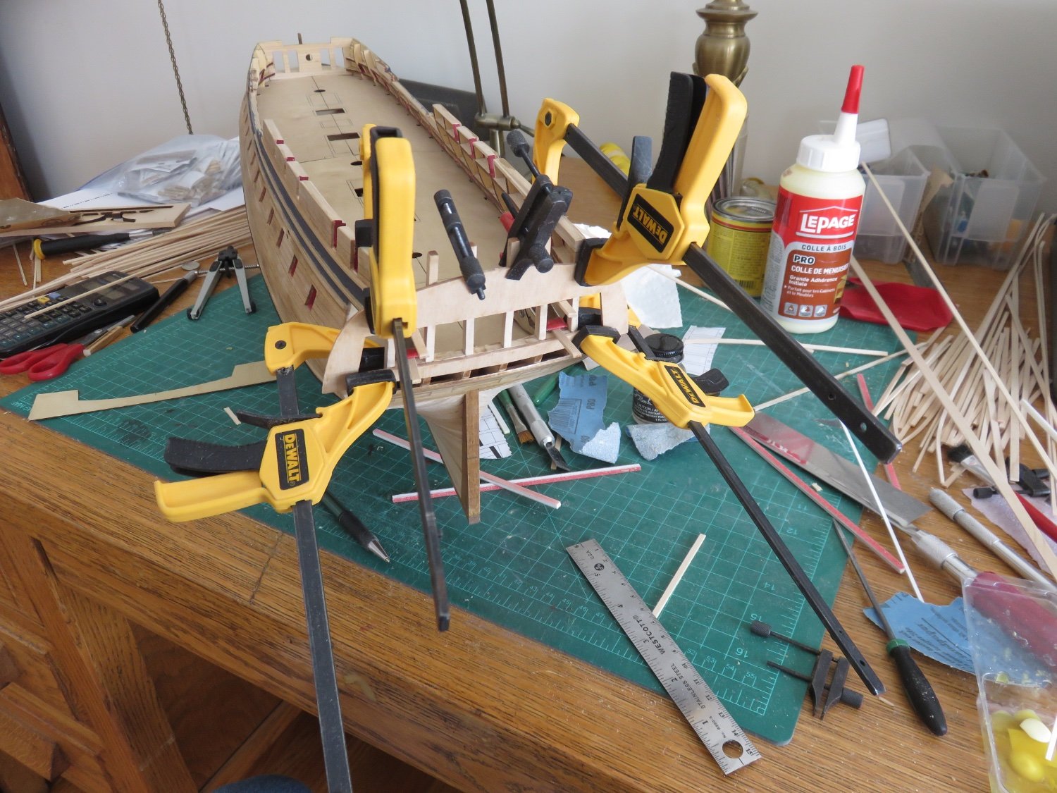
But was not lost. I hauled out the fret from whence the transom came. The stern window curves are essentially parallel to each other and the bottom edge, so I cut a section out of the fret to replace the curly piece.
Aside from a couple of faint lines (not visible due to the clamps), the repair was successful, the transom reinstalled, and after a little bit of clean up, work can continue moving forward again. Until the next speed bump.
I should add, that despite the warping issue, the acrylic paint thinner does a great job at de-bonding PVA. It contains glycol ethers, but it doesn't evaporate quickly like isopropyl alcohol, so it can really soak into the joint and soften the glue.
Andy
-
30 minutes ago, Kevin said:
sorry i missed the restart of you log, great to have you posting again,
lovely build, the planking looks fantastic
Thanks Kev!
It’s not so much of a restart as it is a stop-messing-around-and-show-your-work kind of thing. So you really haven’t missed too much as far as this log goes 🙂
Andy
-
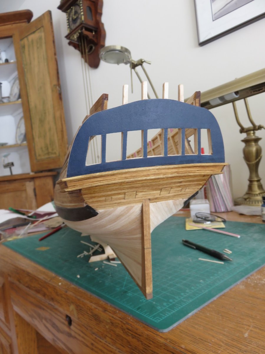
Finally something other than planking!
To start off, as mentioned back in my first post, the stern frames had suffered as a result of unintentional contact with the nose of a curious canine shipyard helper. While I did affect repairs at the time, some tweaking was still necessary. First up was the stern light cills and lintels:

With the help of the original paper template, and the laser cut windows themselves, and the use of the liquid in the jar with the black label in the above photo (acrylic paint thinner), I managed to get the pieces positioned in their correct locations.

For the second part, I cut off the stern end of the false deck fret and used it as a template to check the curve of the stern frames and ensure that they made as nice an arc as possible. I had noticed when first I dry fit the transom, the curve was far from smooth... it was rather wavy. I checked with some scrap pieces of wood against the current frame thickness vs the final frame thickness after internal fairing (a few steps ahead in the instructions). It was clear that the easiest way was to simply sand down any high spots, rather than try to shove things around. This soon had things looking much better.

A final (?) dry fit of the transom, and things look pretty good. I'm not sure why, but I'm still apprehensive about getting the glue on yet. I'll get there, eventually.
Andy
-
Thanks to everyone for the kind comments and likes!
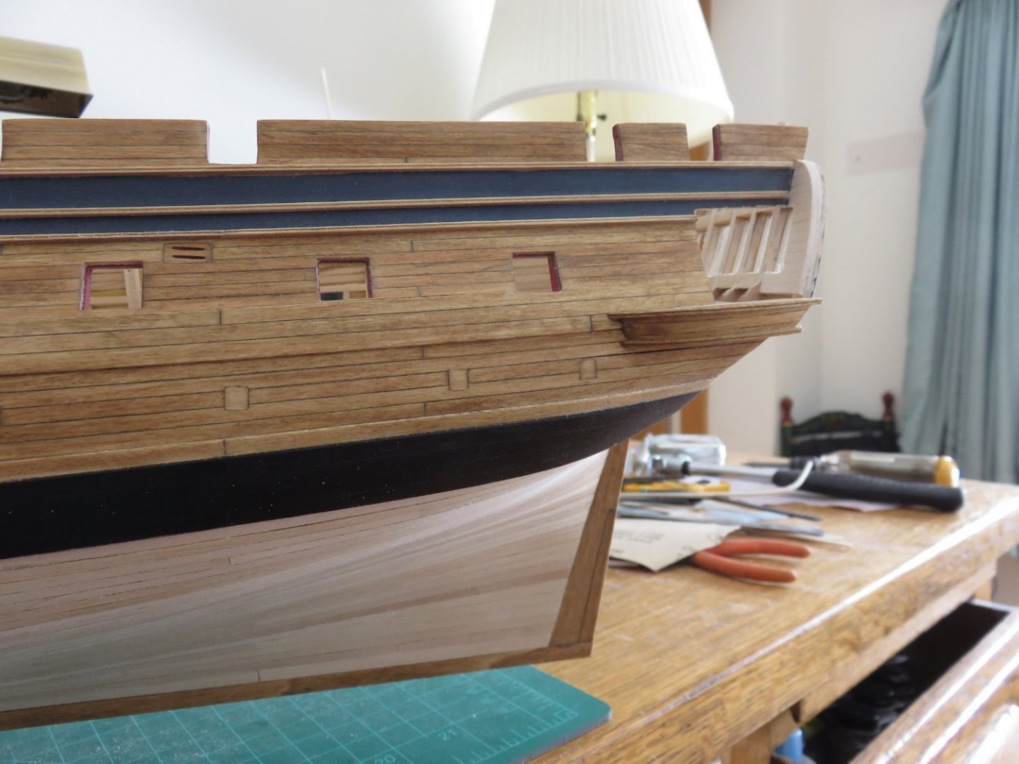
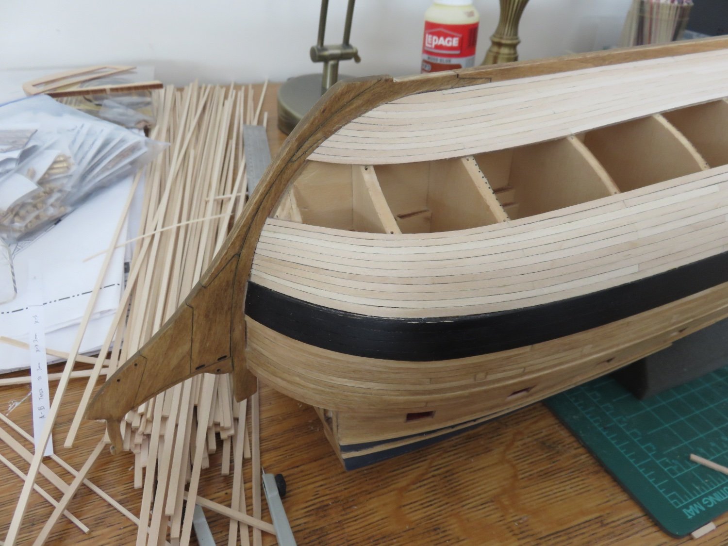
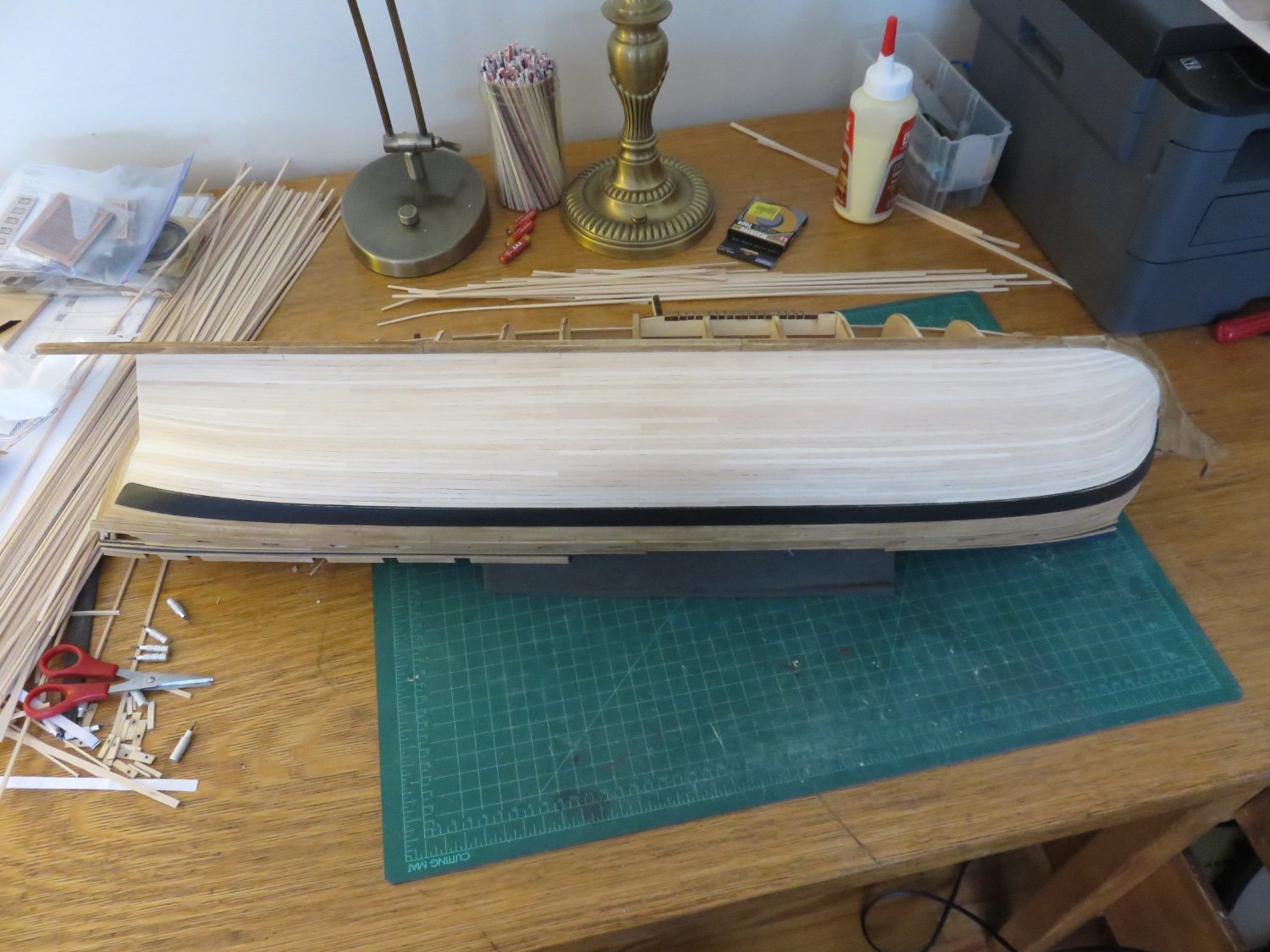
Yesterday was a bit of a milestone day. The hull planking is finally finished! Hooray!
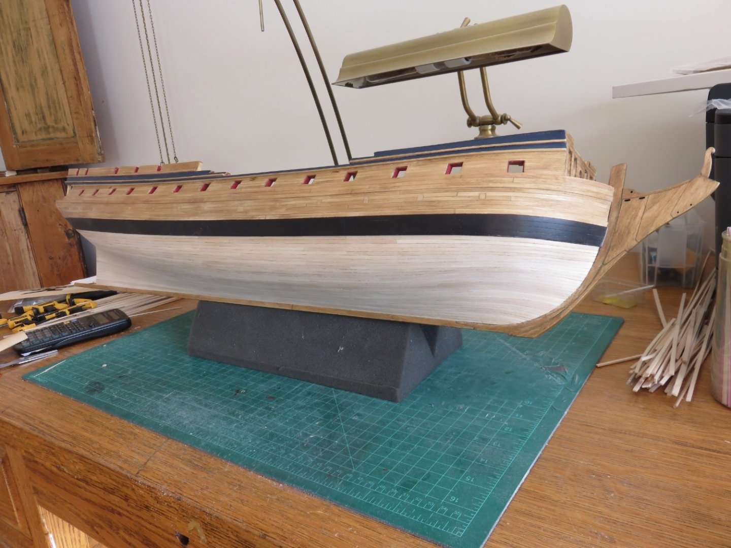
As you can see, I decided to fully plank over the reveal section. It partly came down to personal preference, and partly because over the course of the several years that I have been building (storing, transporting, shuffling aside) the model, some of the frames segments had accrued some small dings and dents (a small drawback of basswood).
I've just completed prepping and staining the stern post, so while that dries, time to grease up the old elbow and get making some dust!
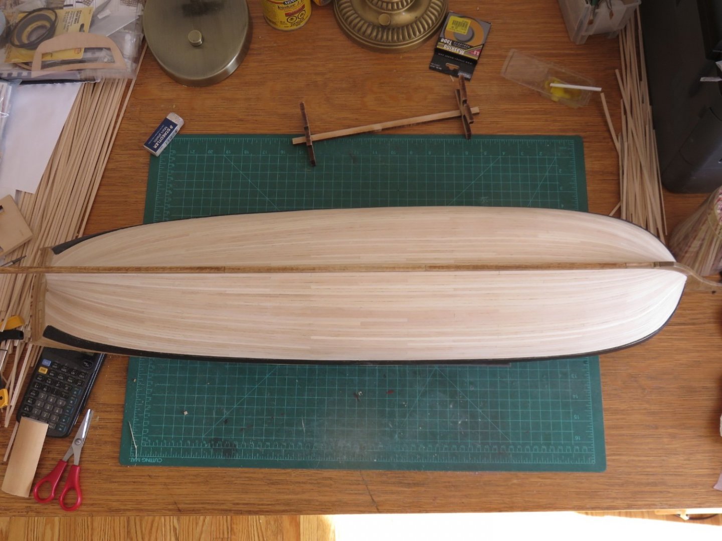
I really enjoy the sense of satisfaction one gets when a hull has been completed, and I am particularly enjoying the relief that comes knowing I don't have to go all over it again with a second layer (big "YAY"!).
Andy
-
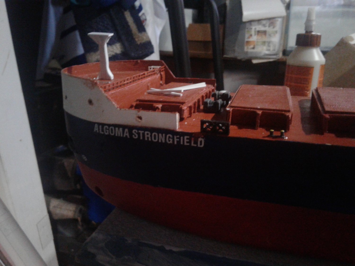
Sackville is only a year newer😜
I was more trying to help with the smoke cans on the stern, which are visible on her. Was there some drastic change in equipment?
Andy
- Old Collingwood, lmagna, Canute and 2 others
-
5
-
12 minutes ago, yvesvidal said:
I understand that for some modelers, this rear deck seems a little bit empty and I completely agree with that opinion. I wish the kit provided the famous "Smoke Float Canisters" which are usually sitting on top of the depth charge chutes. I tried to study a few pictures of the stern of Snowberry, but could not get much in term of details or equipment. Most of the pictures I have seen are crowded with sailors, making it difficult to see what is installed on the deck. I should definitely place some ropes, laying on the deck....
Would this help:
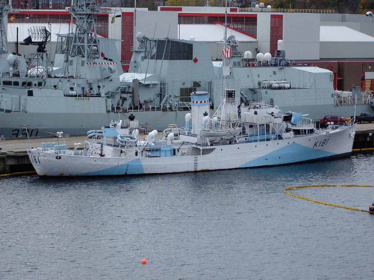
(HMCS Sackville for those who are curious)
There's a closeup photo in this article
Andy
- AON, king derelict, GrandpaPhil and 5 others
-
8
-
27 minutes ago, CiscoH said:
Great planking job Andy.
I was wondering where you got the small black miniature screw clamps in the first and third pictures of your first post. I can't find them, or maybe my google description isn't right.
thanks, cisco
Thanks!
I got those clamps years ago from Lee Valley tools. I don’t know if they still sell them. Try searching for “miniature machinist clamps”, or “tool maker’s clamps” see if that works.
Andy
-
A few weeks since my last update, so just a quick one to show that I'm still working away at it. Construction has slowed slightly since winter finally arrived a couple of weeks ago. Lots of fun outdoor activities, like skiing, sledding, snowshoeing, all the fun stuff that can only be done with a decent amount of the white stuff. And then for those who follow my non-maritime adventures, there's also the odd time when my main mode of transportation decides to no longer function as designed.
Anyway, on the days not filled with other activities, work has progressed on the starboard side, and I've now managed to complete the first two planking belts.
It's nice to begin to see the (hull) planking finish line.
Andy
-
Oh no!
I hope you’re ok, though.
Andy
- Canute, Old Collingwood, mtaylor and 2 others
-
5
-
The interior of ballast tanks (of that era), if they were coated, probably would have been a coal tar type paint: black.
Andy
- mtaylor, Old Collingwood and Kevin
-
3
-
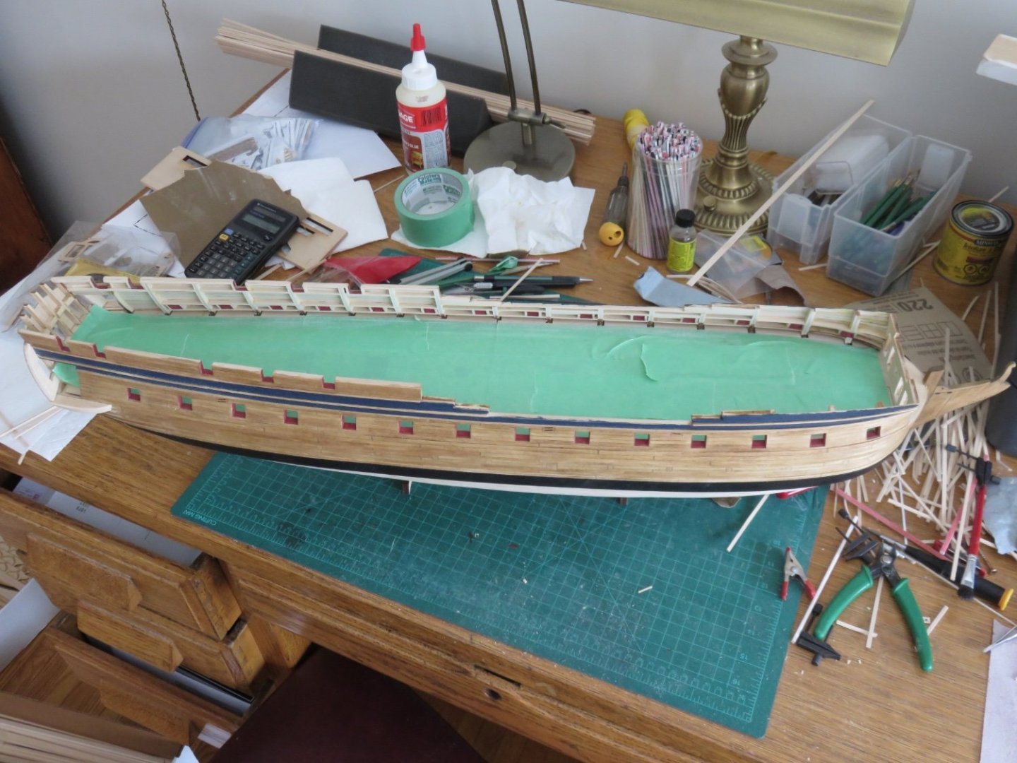
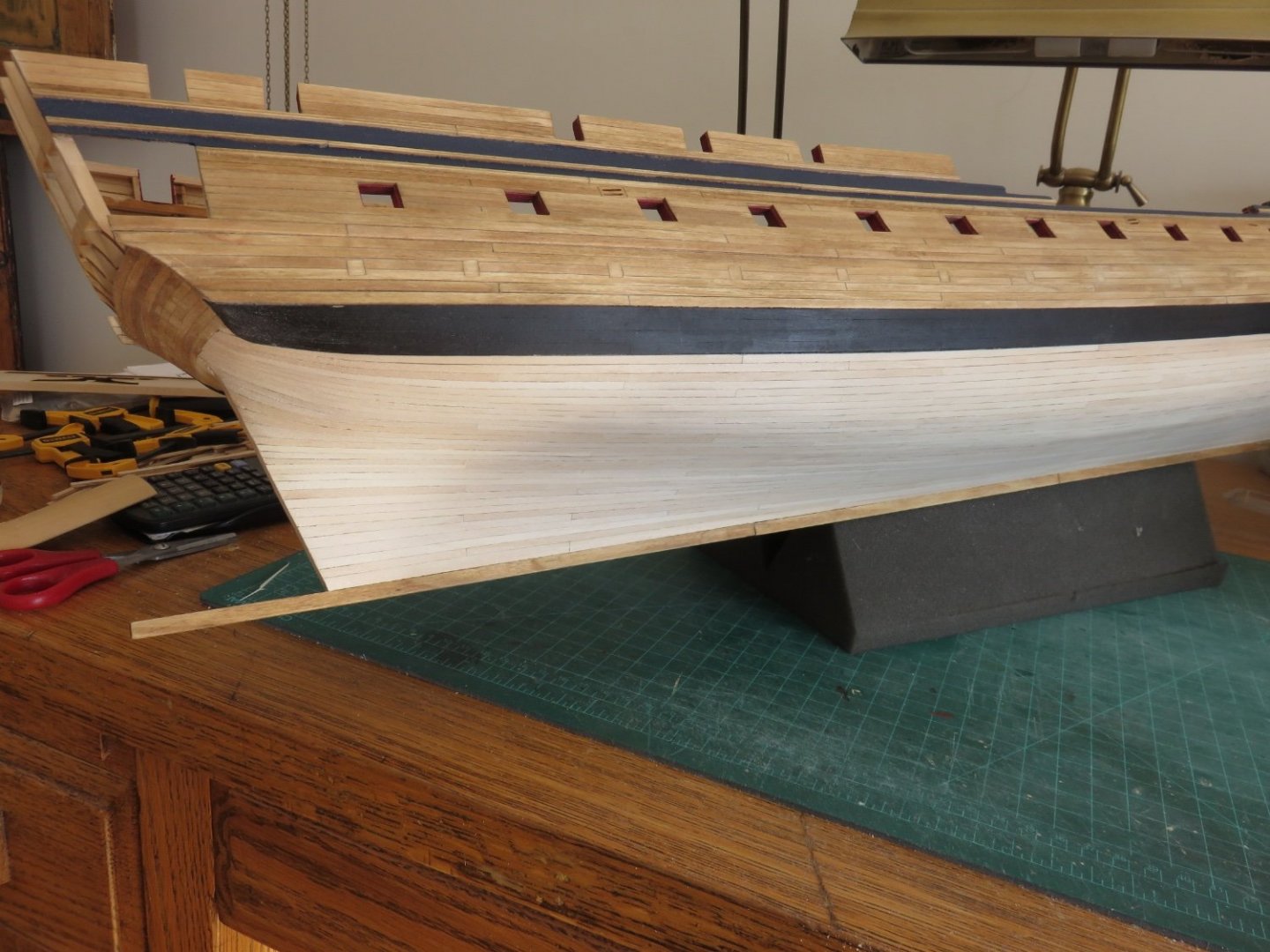
A bit of an update to share on an otherwise grey Sunday morning (at least where I am). I have managed to finish the planking on the port side yesterday.

I think I've managed fairly well with it. By no means is it perfect, but I'm happy with the overall result.
I've given it a cursory sanding, there are a few spots that still require a little more work (nothing major), but I will get them after I've finished the starboard side.
Andy
-
50 minutes ago, Roger Pellett said:
You mention a feedwater tank so this must have been a Steamship. This is somewhat surprising because by the 1860’s the large slow speed direct drive diesels were favored by many owners and of course Sunderland was home to Doxford, an early proponent of diesel propulsion. Americans were, and still are, one of the few holdouts. They continued to build steamships and when they switched to diesel, it was the medium speed engine with reduction gears and/or CP propeller.
Even diesel boats today still have a small steam boiler. Either a small oil fired unit or an exhaust gas economizer (waste heat recovery), and very often both. Although not used for propulsion, the steam would be used to heat fuel oil (IFO is thick as molasses at room temperature, HFO even thicker), for warming the engine (via heat exchangers) prior to starting, and other auxiliary uses (hot water for the crew). The boiler(s) would require it’s own feed water tank as there are various caustic chemicals needed to prevent corrosion and sediment build up, that you don’t want in general circulation.Andy
- Old Collingwood, mtaylor, Canute and 1 other
-
4
-
You can rule off the blank decal sheet and the transfer sheet with a pencil and by lining up your pencil lines (which should be easier to see) you should be able to get nice straight words. The pencil on the decal sheet can be erased carefully afterwards.
Although I’ve never built one before, I’ve seen a few examples on builders models. They always seem to use brass code 100 track (about twice the size of code 55) on models that are about 3/4 the size of yours and it looks hideously clunky.
Looking at prototype photos, the structure of the crane looks reasonably straight forward, a frame of rectangular steel tubing and three legs on each side. You probably wouldn’t go too wrong using dimensional styrene stock to make the frame. You could probably pick up some cheap N-scale plastic wheel sets that you can use (if you want a real challenge, make it so it can roll up and down the deck!)
Andy
-
Do you have any blank decal paper?
I find it easier to apply the letters on a flat surface, then seal them with Testors glosscote or dullcote. All that remains is to apply them as you would any decal.
Incidentally, if you’re looking for hatch crane track, try Micro Engineering’s code 55 flex track.
Andy
-
7 hours ago, Roger Pellett said:
This project is also related to my ship modeling interest- Great Lakes Shipping. The Duluth, Mesabe, & Iron Range Railroad used these massive engines to pull trains of 100-200 24 ft iron ore cars locally called Jennys from the mines to the ore docks in Duluth and Two Harbors, MN. Each car carried 50-70 tons of ore. So it took 2 to 3 trains to load a 600ft ore carrier.
The huge gravity ore docks in the harbor are still active, although the large 1000ft ore carriers can carry up to 6 trainloads of refined taconite pellets. The Railroad and the former US Steel Steamship Fleet is now a part of the Canadian National Railroad.
I have 10 iron ore cars painted in DM &IR colors and logos. I have a caboose that needs to be repainted and logos added. I have found decals for the caboose, but not for the engine tender.
The engine, ore cars and caboose will be about 5 feet long. I intend to run a shelf with track about 9 ft long along a wall of my man cave. The “layout” for the time being will only allow movement of about one train length.
Roger
Something to ponder:https://www.walthers.com/ore-dock-kit-48-1-2-x-5-quot-121-2-x-12-5cm

Andy


Confederacy by Realworkingsailor - Model Shipways - 1:64 - Frigate
in - Kit build logs for subjects built from 1751 - 1800
Posted
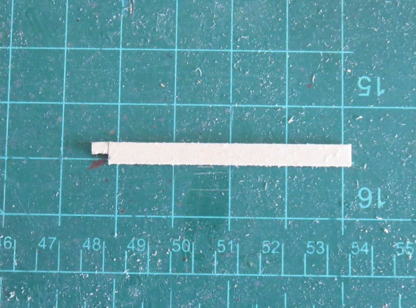
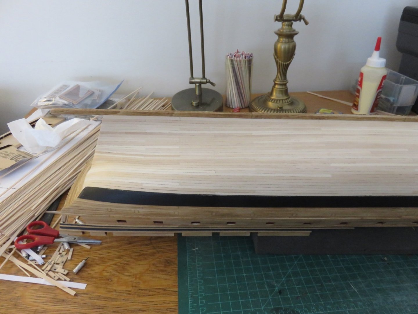
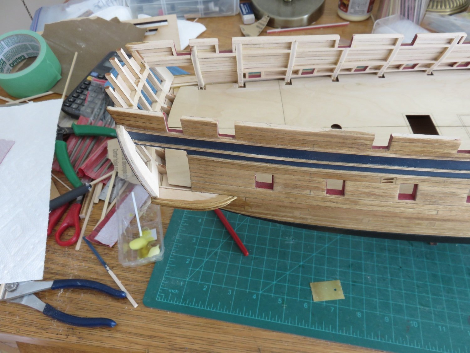
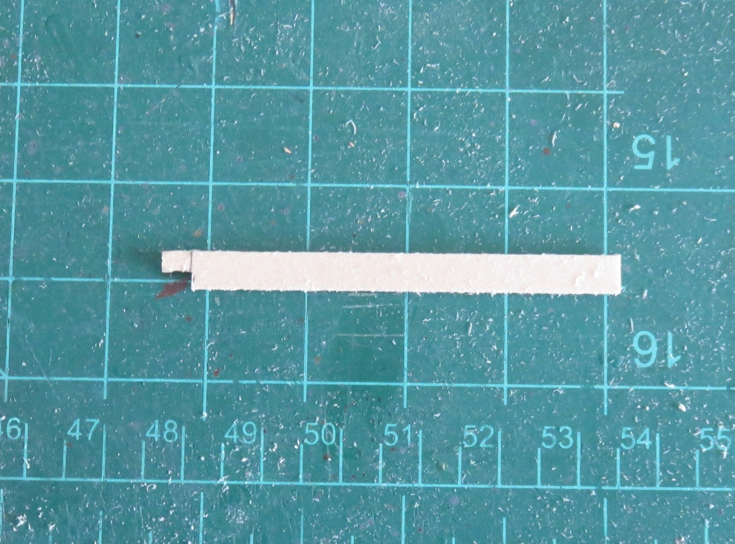
The solution to the problem. Make a new fo'c'sle clamp from scratch. This is by far the best way (fingers crossed) to ensure that everything will be as it should be going forward.
The laser cut piece is on top and my replacement below it. Basswood being fairly easy to work with, basic tools are all that's required (hobby knife, ruler and sharp pencil). I used the laser cut part as a base template, and extended it as needed. The locations for the notches for the frames where measured off the plan (overhead view). A little refinement is still needed, and of course the notches for the beams cut out (which will be double and triple checked vs the plans!)
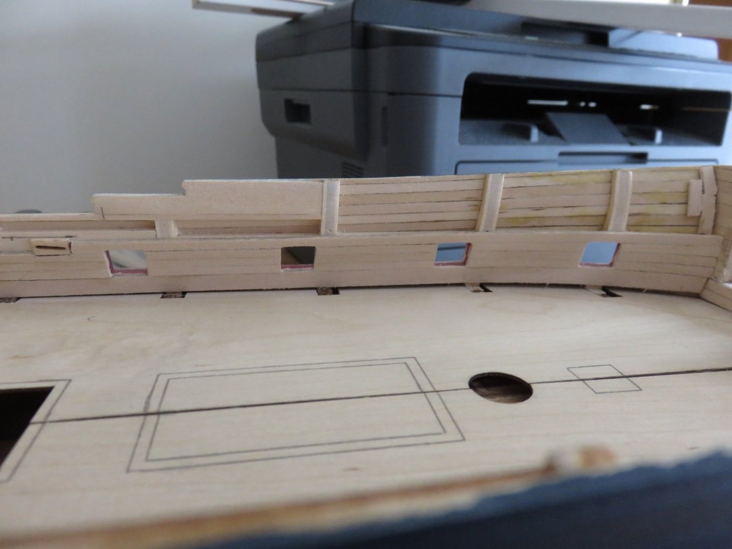
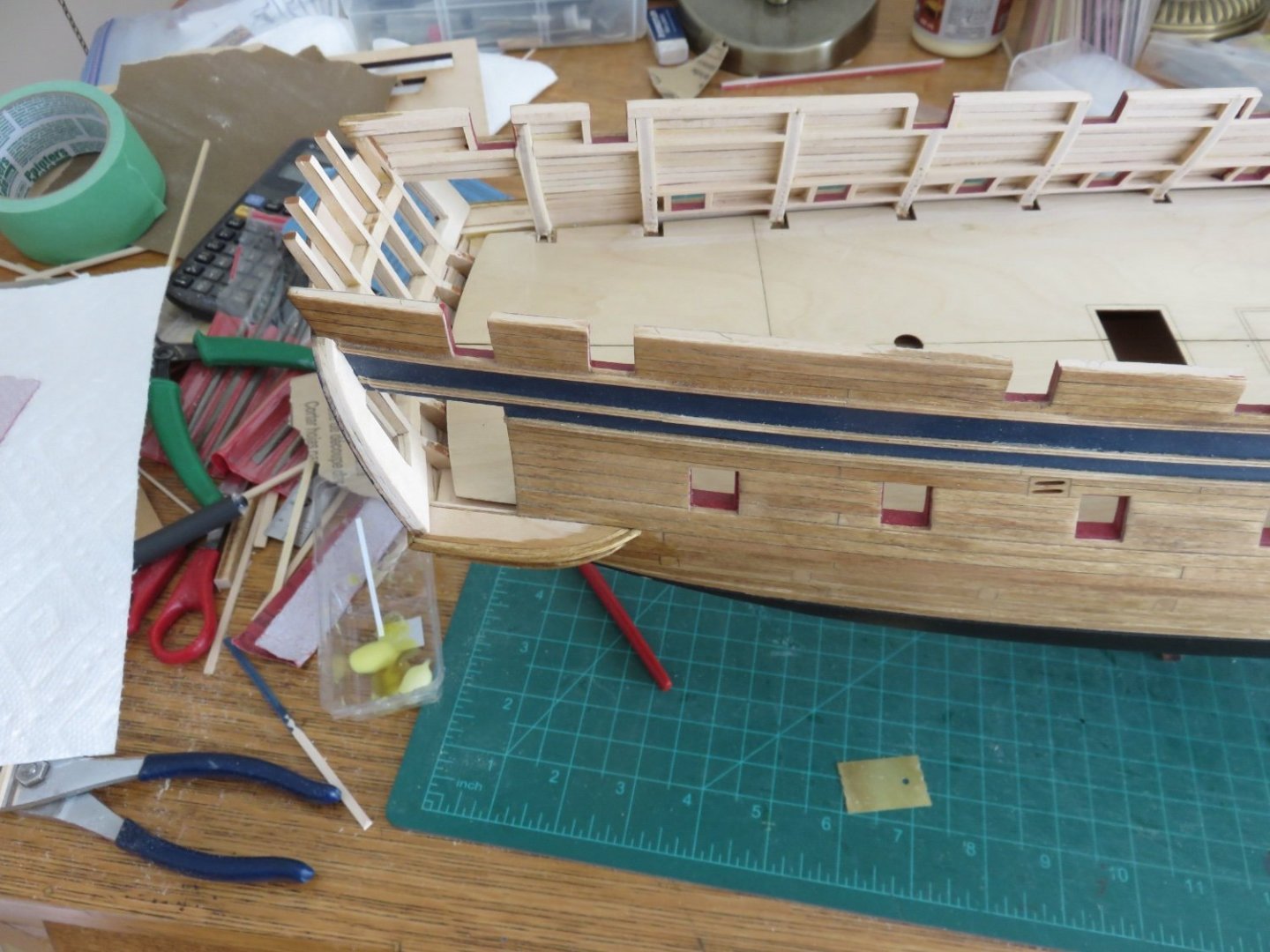
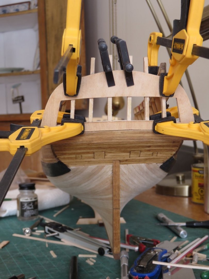
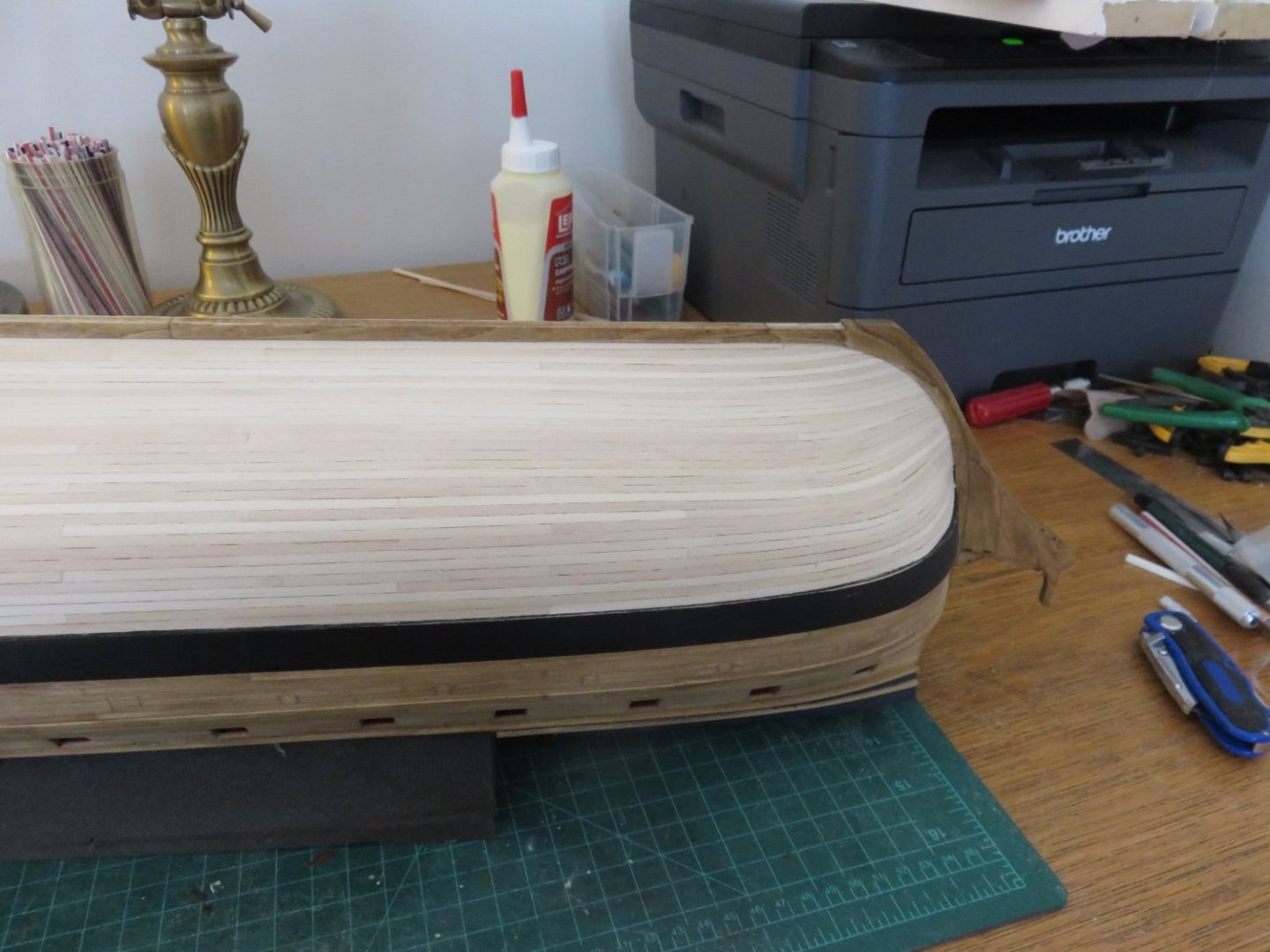
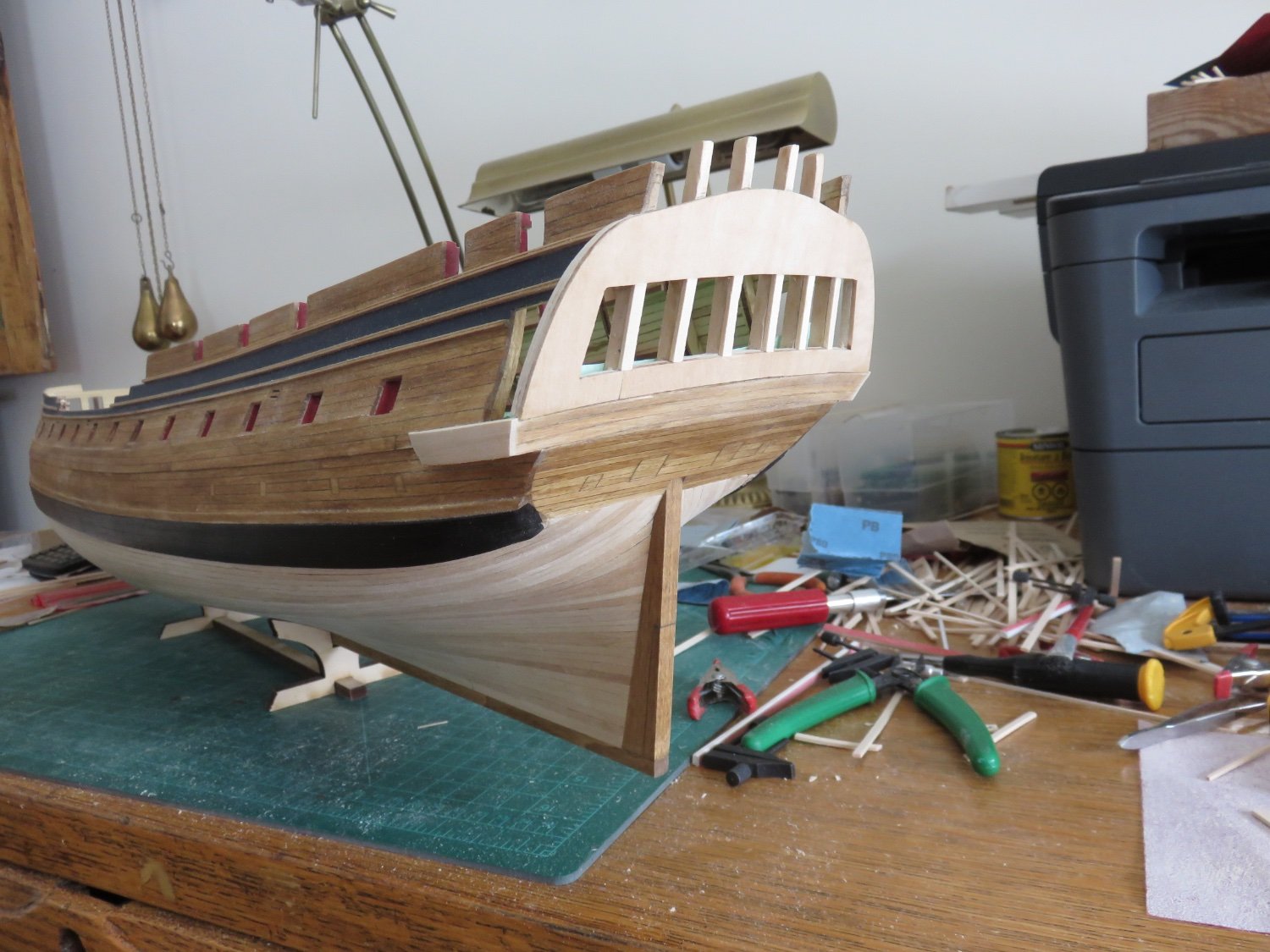
Here's the original clamp in place (with a 3/16" scrap strip below it). The forward end isn't beveled to the bulkhead, so the error at the after end is slightly more than is glaringly apparent in the above photo.
And finally the replacement in position. The forward end has been roughly bevelled, and the aft end will need a little bit of further refinement (the whole piece, to be honest), but this is something I can work with. Notice how the beams now will actually line up with etched marks for the base of the stove, which looks correct as per the plans, and even more critically, they're now spaced equidistant from the foremast.
Onwards!
Andy