


AnobiumPunctatum
-
Posts
1,283 -
Joined
-
Last visited
Content Type
Profiles
Forums
Gallery
Events
Everything posted by AnobiumPunctatum
-
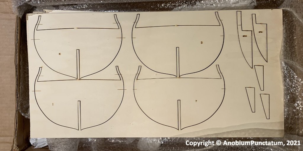
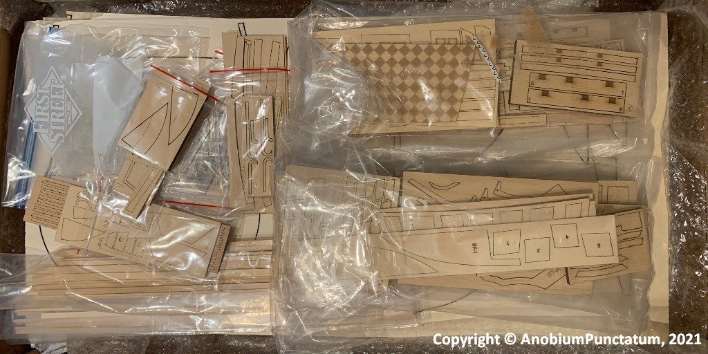
Yesterday I picked up my package with the parts for the first four chapters at the German customs office. I am really impressed of the quality and what Chuck can do with his laser. Now I am waiting for the extra timber I ordered by Chuck. And then the adventure can start.
-
Really interesting approach and a lot of preparation works.
-
Your counter is looking really nice.
-
A really informative buildlog, Ben. I like your idea, to show some dummy frames.
- 399 replies
-
- 2
-

-
- winchelsea
- Syren Ship Model Company
- (and 1 more)
-
You're right. And you use a primary source. That's the reason why I said that I will rethink my ideas. Can you give me a date for the logbook-entry? Was it fore of after the large repair from 1780/82?
-
I don't know the log. I am a really surprised that the ship had 24x and not 26x 12 pdrs. Here are some further information, which I found in modern books (which are not primary sources): I found in Robert Gardiner "The first frigates" for the armament (22/07/1782) of WInchelsea: Quarterdeck: 4x 6pdr long guns; 6x 18pdr carronades Forecastle: 2x 6pdr long guns; 2x 18pdr carronaeds. Further gives the book the following information for the armament of the Niger class: Design: 26x 12 pdrs (upper deck), 4x 6pdrs (quarterdeck) and 2x 6pdrs (fore deck) Added by Admirality orders: 11/11/1756 12x 1/2pdr swiffels (quarterdeck and fore deck) 10/081779 6x 18pdr carronades (quarterdeck) and 2x 18pdr carronades (foredeck) 25/12/1779 4x 18pdr carronades (quarterdeck) and 2x 18pdr carronades (foredeck) 19/11/1794 4x 24pdr carronades (quarterdeck) and 2x 24pdr carronades (foredeck) Winfield (British warships in the age of sail 1714-1792) confirms the information. Winchelsea had a great repair form 03/1780 until 04/1782. During this repair the ship was copperd. There is an information which I don't understand in the moment ("re-rigged with 28-gun ship's top hamper") . I've never heard "top hamper". Does anyone knows, what this means? My plan was to show the ship with carronades. But with the information from Chuck, I have to think about this.
-
MONTAÑES by Amalio
AnobiumPunctatum replied to Amalio's topic in - Build logs for subjects built 1751 - 1800
Really wonderful. This model is art. -
Your stern is looking really beautyful.
-
@scrubbyj427 If you like this appearance you can reach this with our group build model. Winnie in her 1782 appearance should looking really similiar to Minerva. So it's not necessary to dream from another model. Have fun with the group build.
-
Hartelijk welkom in de Winchelsea werf. Ik wens je heel veel plezier met dit mooie project. Welcome to the Winchelsea shipyard. I wish you a lot of fun with this beautyful project.
-
Thank you Chuck👍
-
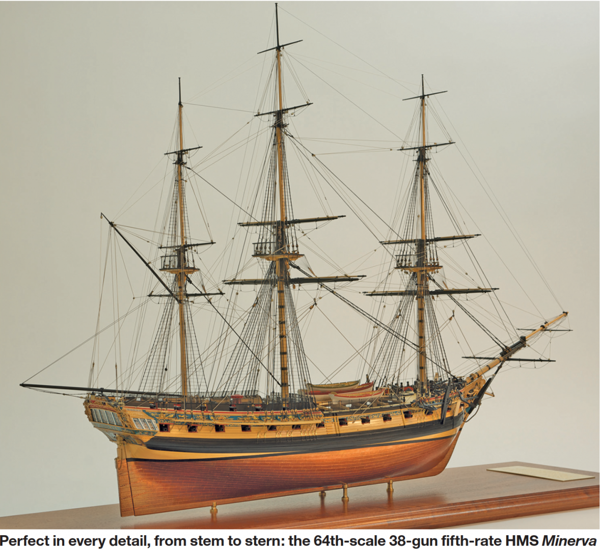
The following photo shows a really wonderful modern model of HMS Minerva, which shows the beauty of an fully rigged frigate. It's my model and motivation for the build of HMS Winchelsea. Picture from Country-Life, April 2011 HMS Winchelsea had a really long career in the Royal Navy and it's possible that the ship is looking similiar to the model of Minerva, after the great repair of 1780-1782. I don't know if I will copper my model of if I will show an older condition of the ship. @Chuck You show in your log photos of the origininal model of HMS Winchelsea. I couldn't find a gallery with all photos. Is it possible to make a gallery? This makes it much easier to find this very informative pictures.
-
Whow, you have a really nice workshop. My shipyard has 8m² and is now also my homeoffice. I am very interested to see your method of building a hull. It isn't very popular in Germany. I know this method only from older books about shipmodelling.
-
Thanks very much for your interest on my buildlog. Greg, I will later continue with my other projects, especially Fly and Triton.
-
Whow, I didn't realize how the last year flew by. I actually wanted to start with my model much earlier, but due to the Corona crisis and a project change, I gave up my second home in Amsterdam and moved back home. I now have to use my shipyard as my home office, so scratch building isn't really a good option. At Christmas I found the offer of ir3 at MSW and considered using the small lasercut kits from Chuck to pursue my hobby. In the meantime, the decision has been made and I am waiting for a package with the components. After Chuck reopens his store I need to buy some yellow ceddar and then I will start my build. I dream to fully rig WInchelsea later. Frigates are in my opinion some of the most beautyful shipmodels with a rig.
-
Good morning Chuck, I found in W.E.May "The boats of the Men of War" that there were two different options for a fith rate with 32 guns: 1761: 3 boats - 23ft longboat, 30ft pinnace and a 24ft yawl 1781: 5 boats - 23ft/ 24 ft launch, 30ft pinnace, 2x 18ft cutters I think it should be nice to show all boats with the ship.
-
Is this offer available? I am interested. Do you ship to Germany and what are the shipping costs?
-
Chris, is it possible that you offer the Armstrongs and also the Blombfields in scale 1/48?
-
Hi Tony, a really wonderful buildlog and a beautyful model. It was a pleasure to read through your log. The fashion piece is really tricky. It took me also a litttle time and some hints from druxey, until I understand how it works.
-
Wow, that was a lot of progress in the last few month. Your model looks so beautyful. Viewing on the pictures is a big motivation to continue woith my own model. I have one question: where did you get this beautyful guns?
-
I will take a seat and follow your log with great interest.
- 179 replies
-
- 2
-
-
- longship
- Helga Holm
- (and 1 more)
-
I understand what you mean. That's also the reason, why I didn't start building the Oseberg or one of the other bigger viking ships. The stopped Skuldelev III was a not so nice experience. But I love this kind of klinker build ships. But before I go back, I will finish my HMS Triton; but this project needs some more years to complete.

