HOLIDAY DONATION DRIVE - SUPPORT MSW - DO YOUR PART TO KEEP THIS GREAT FORUM GOING! (Only 13 donations so far - C'mon guys!)
×


AnobiumPunctatum
-
Posts
1,280 -
Joined
-
Last visited
Content Type
Profiles
Forums
Gallery
Events
Everything posted by AnobiumPunctatum
-
ancre La Salamandre by tadheus - 1:24
AnobiumPunctatum replied to tadheus's topic in - Build logs for subjects built 1751 - 1800
Very nice, Pawel -
Very good video, Kenny. Your hints and -sorry to say- your small inaccuracies are very helpful for me, to avoid the same mistakes. Normally a model maker doesn't like to show these details. But these are the points which will help others. Thanks for sharing
-
Hi Roger, exist a build log of your long boat? I am very interested to see your model.
-
I agree with, Daniel. For a ship of the later 18th century, Druxey is right. For a dutch ship of the 17th century option d is also possible.
-
Daniel, I was in the Netherlands for a job last week. I know that I am a bit to late. If it is possible to get the Utrecht for the preorder price. I like to order a kit.
-
Congrats for reaching this first milestone of your project. I think you have to be very proud about your model
-
Really wonderful project. I've never seen a working boat like this before as a model
- 525 replies
-
- 3
-

-
- anchor hoy
- hoy
- (and 1 more)
-
How much are you willing to pay
AnobiumPunctatum replied to Worldway's topic in Wood ship model kits
I am a little bit surprised. 1000$ for the Amati Pegasus. In Europe the kit costs around 400,- € which are aroud the same in $. Perhaps it is possible to order the kit by a European seller? I don't know what tax you have to pay later. -
Really interesting project. I've never seen this ship type before. Very well done, Anthony
- 99 replies
-
- 3
-
-
- turtle ship
- korean
- (and 1 more)
-
Found your log this morning. Very nice build.
-
Anguriel, the thickness of the regular frames is not that important in 1/48 (1'' is 0.5mm in that scale). If you take the medium thickness and make all frames the same it's absolut ok. I think the typical position of the single and double frames and the special frames at midship are typical for an English ship and special for your choosen pattern. But if you like the fun to build it more close to the original ship, do it the more complicated way. I wouldn't you black paper for the frames. The joint is not stable enough. There exist a one layer pulp, which you will find in a hobby store. If you use this the joint is much better. Black paper should show the caulking. As far as I know there is now caulking between the tmibers of a frame. If you want to higlight the joints, it is better to use brown color which is a little darker than the used timber, Have a look on page 4 in my build log.
-
Anguriel, I checked the values. They are correct. I've had a look to my drawing project. At cutters the first futtock is also wider than the floor timber. As far as I remember the position of the gun ports of the group build matchs the original drawing.
-
Anguriel, I will check it this evening.
-
No problem, here are the values for the regular frames from Elements of Naval Architecture (Steel): floor timber: 12 1/2'' 1st futtock: 13'' 2nd futtock: 11'' 3rd futtock: 10 1/2'' 4th futtock: 10 1/4'' top timber: 10'' Source: Allan Yedlinsky: Scantlings of Royal navy Ships 1719-1805, SeaWatchBooks LLC, 2014
-
Your progress looks quite good.
-
Aguriel, if you have Antscherls TFFM have a look in volume 1, page 88. There is a description for the correct position of the treenails in the chocks. To your observations and questions: correct correct correct Yes, only the floor timbers and first futtocks are glued together. The timbers for the other frames are thinner and there the double frames will be connected with spacers. B and D are single frames. The change of double and single frames is common for English ships of this period. Frame 0: floor timber 1ft 4in, second futtock 1ft 3in, fourth futtock 1ft 1in; Frame 1 and (A): first futtock 1ft 4in, third futtock 1ft, 2in, top timber 1ft 1in That's a question of what you want. In the group build all timbers ofthe frames have the same size. In the original ship the timbers will become thinner. In my opinion and if this is your first try I would follow this simplification. If you like to know the correct sizes I will have a look in my book. Yes, there are the spacers. If you follow the dimensions in the books the top timbers are 1/4in smaller. I think that this is negligible in 1/48. The position of the gun ports gives the position of the frames The sizes of the timbers and the tolerances define the space. I would start to build the double frames and position them correct. Then I would add the filling frames (single frames) regular between them. See answer 6
-
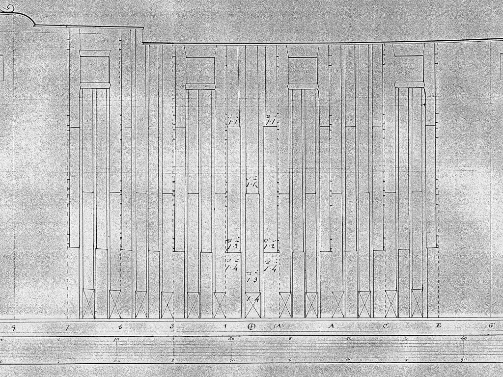
Your frame is looking really good. The joints a very clean. Have you used a black pecil for showing them? I would only use a light brown pencil. If you don't understand the drawing, please ask. I am happy if I can help you. I hope the following information help you to understand the drawing a little bit better. The drawing is a part of the originial Disposition of Frames Drawing for HMS Triton. It shows the arrangement of the frames. The small numbers and letters at the bottom indentify the station lines. The midship frame is at station 0. It is a single frame with a thickness which is not common for ships of this period. Therefore the shipbuildes have given the dimensions of the different timbers. The next frame is a double frame. From the second futtock to the top you see a double line, because there is air between the frames. To connect the frames spacers (small timber blocks) are necessary. Under the gun ports are two single frames which have the regular dimensions. Allan Yedlinskys book is a fantastic reference for finding the correct dimensions. The next frame is a double frame, also with air ventilation. If you need further information, please let me know.
-
Aguriel, if you build the frames original,why don't you use the original frames design? You can use the pattern of the Group Build for this, if you let a little bit timber outside of the lines. It would be very interesting to see the 3 thick frames at station 0.