


starlight
-
Posts
146 -
Joined
-
Last visited
Content Type
Profiles
Forums
Gallery
Events
Posts posted by starlight
-
-
Hello @MangoFox,
It seems like you've got a good grasp on what needs to be done. It's always difficult to explain hull planking without actually being there in person. At least for me there was only so much I could do by reading this forum, I had to learn by experience in the end. I don't think anybody ever gets the planking on their first build perfect. Here are some tips I might offer:
-
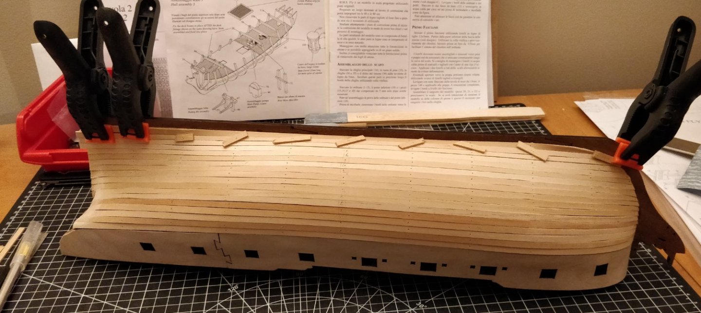
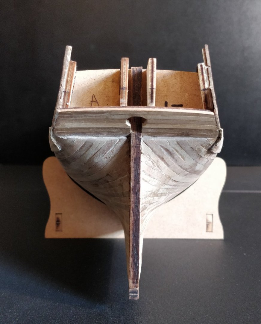
The LN kit should come with brass pins for the first planking, no? For the severe curvature at the bow and stern these might help to hold the plank up tight against the bulkhead. Just make sure you pin them through some sacrificial material or you'll never be able to remove them (see pic below). For the second planking you can use CA glue here and there for the same purpose.
-
Are you beveling the edges of the planks? This should be done especially in areas of tighter curvature to reduce gaps (see pic below). You will also get a small difference if you measure up your tick strips against the inner or outer surface, if that makes sense.
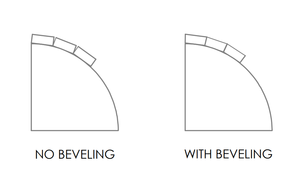
If your planks are edge bent and twisted properly you should be able to avoid the clinker effect. But do treat the 1st planking as a learning experience as you can afford to make mistakes here.
Hope that helps,
starlight
- Paul Le Wol, Ryland Craze, MangoFox and 1 other
-
 4
4
-
The LN kit should come with brass pins for the first planking, no? For the severe curvature at the bow and stern these might help to hold the plank up tight against the bulkhead. Just make sure you pin them through some sacrificial material or you'll never be able to remove them (see pic below). For the second planking you can use CA glue here and there for the same purpose.
-
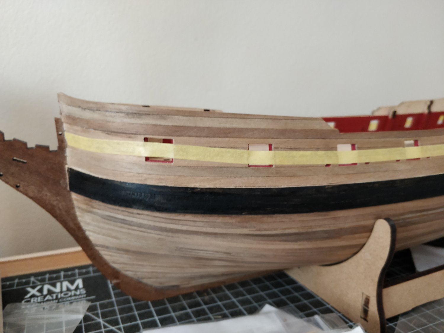
On 10/3/2022 at 6:23 PM, Blue Ensign said:
The relationship between the bridle port and the others Is fixed as they are pre-cut on the pattern. The rail runs between the ports, above midway height, does your tape need a little tweaking?
There seems to be two options:
Run the rail smoothly along the hull letting it cross the Bridle port where it does.
Remove the planking in the area of the Bridle port, and infill to adjust the shape before re-planking. In this case the width of the Bridle port could be made slightly narrower, as was the actual case.
I think it more important that the rail looks to have a smooth sweep along the hull.
B.E.
Thank you Blue Ensign,
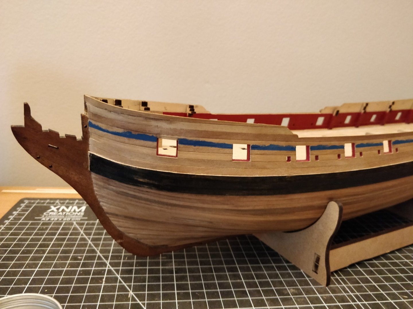
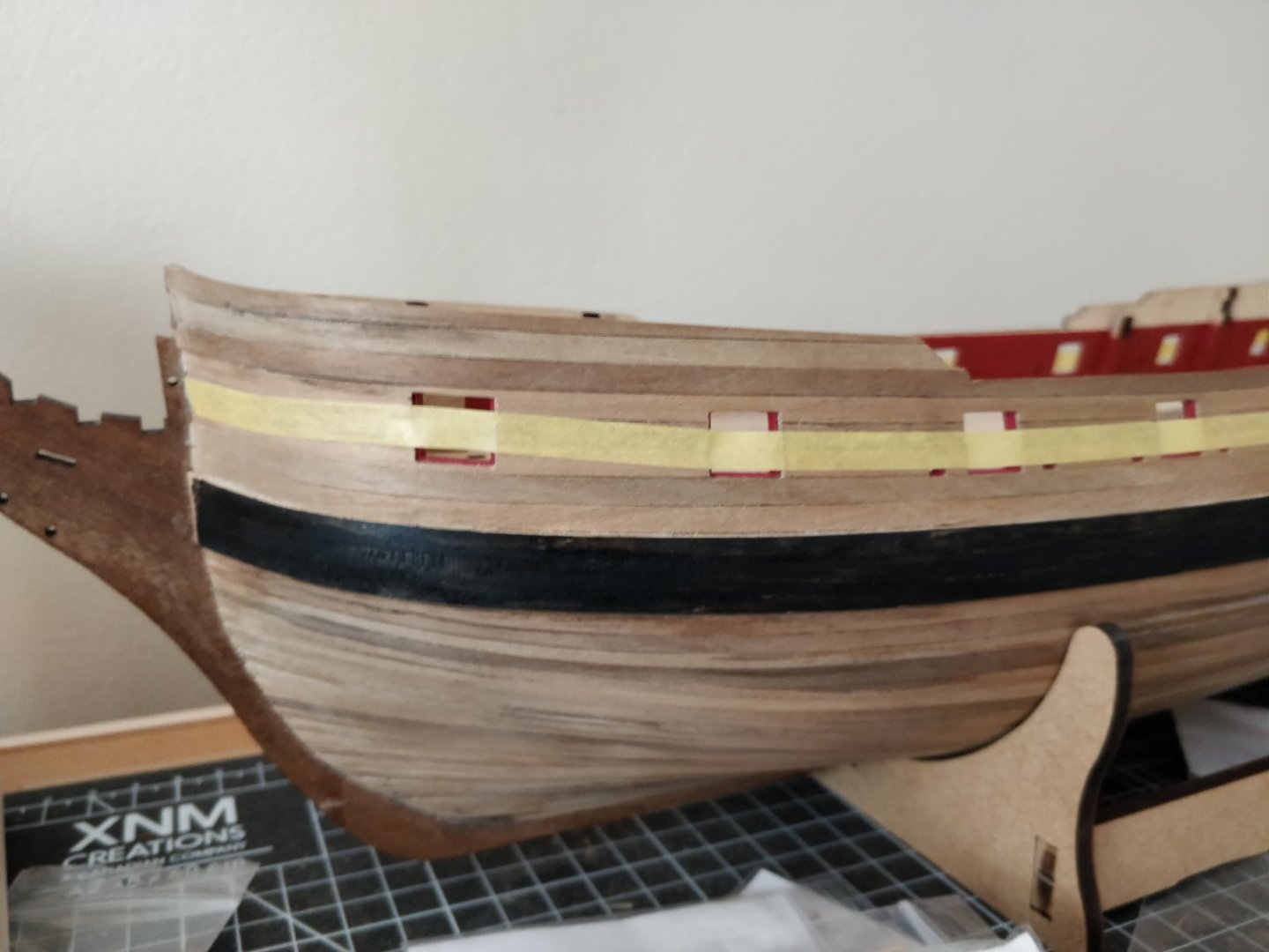
I went ahead and lowered the bridle ports by about 2 mm. The run of the waist rail looks better to my eye now, but time will tell if this causes other problems. I did not end up reducing the width of the ports because I didn't think I could achieve a satisfactory result after laying new hull planking.
(lower edge of blue paint represents top edge of waist rail)
-
On 10/3/2022 at 4:25 PM, ccoyle said:
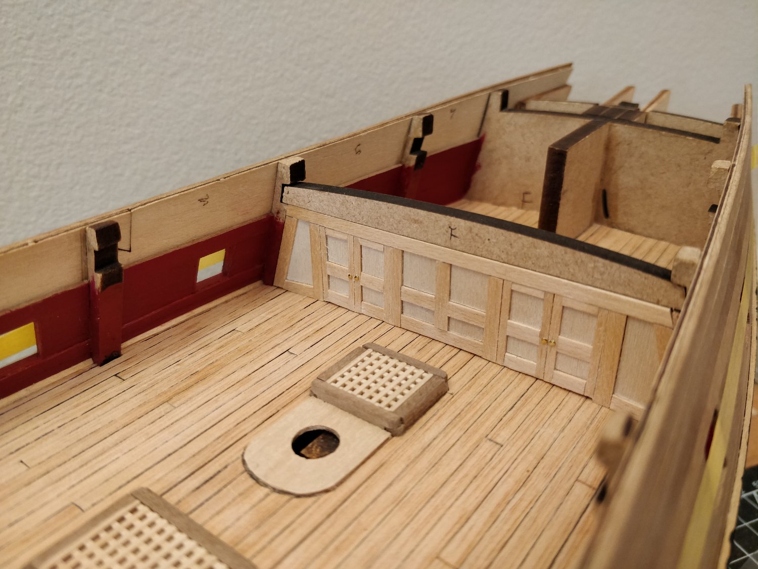
Yep, beneath the grating is definitely not correct, as the beam would largely block the open grate and thus defeat the purpose of placing a grate there in the first place.
Thanks Chris, unfortunately this is the way the kit has been designed. Based on the other gratings I have made so far, it is hard to see through them so the beam would probably go unnoticed. I may just stick with leaving the bulkhead partition panel in this location since it will also be barely visible.
-
On 9/15/2022 at 3:48 PM, ccoyle said:
I made this modification many, many moons ago, so my memory may be a bit fuzzy, but I seem to recall that the proper location for that beam is actually forward of the kit bulkheads. You can check this with the false quarterdeck to see whether the beam lies beneath the opening for the quarterdeck grating or not.
Hi Chris, I completely forgot to reply to your comment. Currently the kit bulkhead beam (and by extension my partition panel) lies under the quarterdeck grating. Is this the proper location?
Measuring from the RMG plans for Fly suggests that the bulkhead panel should actually be moved a bit further aft:
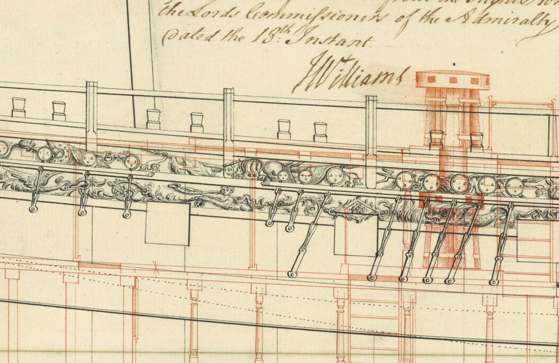
-starlight
-
Glad to see you started a build log! I'm sure others will jump in with detailed advice to any specific questions you have, so I'll just offer some general advice, from one newbie to another.
- Make sure you read the tutorials on hull planking. You can find them in the Articles Database (in the top bar), under the heading "Framing and Planking".
- Check out as many other build logs as you can for the kit you're building: https://modelshipworld.com/tags/Endurance/ This is the best way to inform yourself in advance to any quirks and issues you might encounter, especially if you're going to be doing any kit-bashing. I myself have bookmarked around 15 different logs for the ship I'm building and have found them immensely useful.
- Plan as many steps ahead as you can (by looking at other people's logs), but try not to overthink things to the point where it no longer becomes enjoyable. The goal after all is to have fun.
Best of luck with your build.
-starlight
-
16 hours ago, mtaylor said:
Starlight,
Maybe a wash over it or before printing? I'm thinking silkspan and tape it to a sheet of paper to act as base and crumple.
I'd think paint might work but too thick so India Ink might be best. Thus, no printer needed except for maybe lines to but that could be done on paper and then lay the silkspan on top.
Thanks again, mtaylor. I was planning on adding furled sails to my model in the long and distant future, so I suppose I might as well buy some silkspan now and do some testing.
- thibaultron and mtaylor
-
2
-
Welcome, Zac.
I too am from Canada and am in my 20's. There aren't very many young'uns like us here on MSW.
")
As everyone else has said, do start a build log. I am also working on my first ever model, and have found it both practical and sentimental to have photos and details of my build process. Besides that, there are so many knowledgeable members here who have answered my questions throughout the years. I'd be glad to have a chance to pay it forward.
Cheers,
starlight
- Keith Black, Dave_E, Ryland Craze and 3 others
-
6
-
Thanks for all of the recent replies! I am curious about how to model one of these floorcloths... I have seen the pattern printed onto paper but it still looks a bit too bright to me. I am seeking a more muted effect.
-starlight
- thibaultron and mtaylor
-
2
-
Thank you @markjay and @JerryTodd for bringing this information to my attention. I had no idea these floorcloths were so common, even nowadays.
2 hours ago, mtaylor said:At one time, I think the Victory had the canvas on the floor. Maybe Google (image search) and see?
mtaylor, I found this stock photo of the cabin on Victory: https://www.alamy.com/stock-photo-the-captains-day-cabin-onboard-the-hms-victory-nelsons-flagship-in-25705347.html
It surprises me how crisp and bright the pattern is, almost like tile! Much appreciated for pointing me in the right direction.
-starlight
- thibaultron and mtaylor
-
2
-
Hi Steven,
The last part of your post set off an alarm bell in my head. I am also a first time model builder. I would simply ask you one question: are you prepared to take on a truly monumental project, one that may take you several years?
Forgive me if I sound like I am disrespecting your skills or motivation. It is just that when I was getting into this hobby, I too was enamoured with the idea of building a ship of the line, and quickly realized from browsing the many amazing builds here that I was way in over my head. I decided to cut my teeth on a simple sloop of war first, and it has already taken me over 2 years (and I still have not completed the hull).
I'm sure others will be quick to chime in, but to start, if you have not already seen it I would recommend this excellent thread by @ccoyle:
Whatever you decide, I wish you luck.
-starlight
-
Hello all,
I am seeking some information regarding the checkered flooring on the stern cabin for English warships of the late 18th century. I understand that it was made from painted canvas and simply laid down over the deck planking, but I have a hard time conceptualizing what this would look like in reality. Are there any photographs of modern reconstructions? Any resources would be most welcome.
Thanks in advance,
starlight
- mtaylor and thibaultron
-
2
-
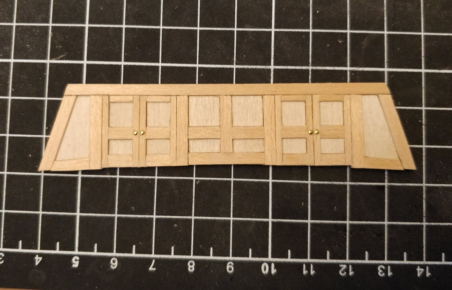
Just another small update for today. As a way of procrastinating on the more important parts of the build, I decided to (once again) copy the great Blue Ensign and Dan Vadas and make a cabin bulkhead:


The frame is made from leftover lime wood strip from the 1st planking, the panels are 1 mm plywood, and the doorknobs are the heads of the brass pins that came with the kit. Still need to add the cants that mount the bulkhead to the deck. I'm afraid it doesn't hold a candle to the builds I based it off of, but I think it's the best I can do with hand tools.
Not sure yet if I will do the other bulkheads. I would still like to open up the stern cabin, just doing some more research first.
-starlight
-
Hello Steve,
You have an exquisitely beautiful model, one that is in fact older than I am. I can only hope to someday have the level of patience and passion to take on such a monumental project as this.
Nowadays we are very fortunate to have access to things like hobby-grade CNC machining, computer aided design, and 3D printing. It's interesting to think about how the art of modelmaking has changed since the early 90s!
Regards,
starlight
- mtaylor and billocrates
-
2
-
41 minutes ago, robert952 said:
@starlight the article link links back to this thread. You may want to edit the link to point to the planking article.
The planking article can be found as you described via the Articles Database link you provided.
Oops, how embarrassing! Fixed.
-
Hi JDillon,
I believe you are looking for a "planking fan". You will find it in the Articles Database (located on the topbar). Scroll down to the "Framing and Planking" section, it is in the article "Lining Off Your Hull Planking, Tutorial and Fan" by Chuck Passaro, one of the administrators here on MSW. I would recommend reading all of the articles and other tutorials before commencing hull planking as it is one of the trickier parts of a build.
Hope that helps,
starlight
-
Hello Moonbug, hope you are doing well. Looking forward to seeing more of your beautiful build!
-starlight
- Dave_E, Knocklouder, AJohnson and 2 others
-
5
-
Hello bridgman,
My first instinct would be to look at resin 3D printing. Assuming you don't have a printer, there are a number of US businesses (e.g. Shapeways) that will print your designs for a reasonable price. Or possibly you could reach an agreement with a MSW member local to your area.
As for the actual design files, you could check online STL repositories, actual industrial suppliers such as McMaster-Carr, or just make your own. If you need these gears to actually function and mesh properly there will be a bit more work involved with tolerancing and getting the proper involute curves.
Feel free to reach out if you decide to pursue this option and need some help with creating the CAD.
Cheers,
starlight
- mtaylor and Keith Black
-
2
-
masa,
Congratulations on your wonderful build and the beautifully-instructive diagrams you've made to accompany it.
Good luck on your next project!
-starlight
-
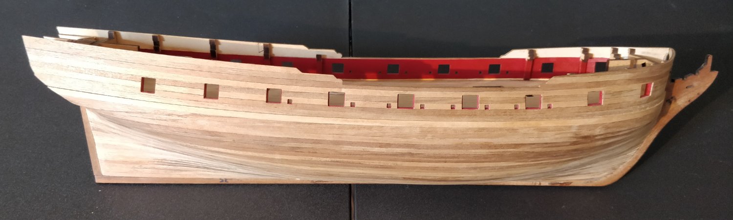
It has been a while since my last post and progress has been slow.
I finished laying down the wales:
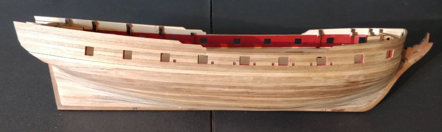
I am reasonably satisfied with how they terminate at the stern, which was a major concern of mine:
It was difficult to inspect the run of the wales so I applied a rough coat of black paint. I then began to lay out the run of the waist rail with tape. I did this by marking off where the rail intersects with the gunports based on the plans. Doing so, I noticed that the bridle ports seemed to be placed too high, creating a clear kink in the rail. This confuses me since the port locations are prescribed by the laser-cut gunport strips. Any advice would be appreciated. It looks to me as though the bridle ports should be moved down by a few mm:
That's all I have for now. I am still working on fitting out the guns and will make a set of posts when they are complete.
-starlight
-
-
Hello Ian,
This is a very interesting subject and I must say you've done some very impressive work so far!
On 5/21/2022 at 11:08 PM, Ian_Grant said:Further tinkering required. It would be cool if I could animate this. Dream on.
I am fortunate to have a student license of Solidworks, which has an excellent motion study and rendering suite. I think recently Dassault released a "maker" license available at low cost. There is also Fusion 360 which I think has the same capabilities but I don't have any experience with it. Certainly, some sort of CAD program where you can verify ranges of movement and linkage designs might be very useful.
Cheers,
starlight
-
Wow, I am very glad to see the attention this thread has received, and am grateful to all of you for your comments!
I asked the original question to get a general sense of when it is okay to use steel, and the answer seems to be: only when the part cannot be made from brass. As for the specific application I had in mind.... I wanted to use some nickel-plated steel dressmaker's pins, painted black, to represent the long transverse iron bolts running through a gun carriage. @Roger Pellett, you are certainly correct that brass would be much better for this purpose, and in fact I did purchase some thinner brass wire for making eyebolts and the like. Only, I forgot about these transverse bolts and am now looking around for something I can use.
@grsjax, @bruce d, @wefalck, @Thistle17: Thanks for your excellent advice on not mixing steel and wood. I wonder how much of a problem this would be if both materials are painted.
@allanyed: Alas, PVA glue was invented around the same time but my model is full of the stuff
. I concede that you raise a good philosophical point on the degree of "realism" that we can achieve in this hobby and the compromises that we must inevitably make.
@clarkt: You've perfectly echoed my worries about rust on the cut ends of steel wire. Glad to hear your first-hand experience.
-starlight
-
Hello all,
Having spent some time now on this site I have read a number of comments from very experienced modelmakers warning to never use steel parts in models due to corrosion. I must admit that I am a bit skeptic about this viewpoint.
In a clean, moisture-free environment, I don't see how steel would not have the same lifetime of say, wood or plastic. Especially in the case of stainless or plated steels, and if kept out of contact with dissimilar metals. And what about if the part is painted?
I would be glad to hear what your specific experiences have been.
Cheers,
starlight
-
@allanyed, @Gregory, thanks to both of you for your comments. I hadn't seen some of those references before so they were quite useful.
10 hours ago, allanyed said:Regarding the tapering the thickness of the wale at the bow, once you add the missing two strakes to complete the main wale a sharp chisel makes this a very easy process followed by a little work with a sanding stick. It looks intimidating but really is not at all difficult.
I will give this some more thought, Allan. I admit I am worried about weakening the planks, exposing the glue, keeping things symmetric, etc. What I should have done was reduce the thickness of the underlying 3 strakes on each side, but at that time I didn't know about the wales tapering in.
-starlight


Checkered cabin flooring
in Discussion for a Ship's Deck Furniture, Guns, boats and other Fittings
Posted
Thank you dafi, the resource you posted is very interesting and I think that level of detail certainly fits a 74 or any other ship of the line. I wonder what would be appropriate for a simple sloop-of-war as I am building.
-starlight