BANYAN
-
Posts
5,965 -
Joined
-
Last visited
Content Type
Profiles
Forums
Gallery
Events
Everything posted by BANYAN
-
 Hi Jason, could it be that if they are equal stacks (same dimensions separated) that one axle set is for the front the other for the rear? Nice simple assembly jig you have set up. cheers Pat
 -
What a fantastic portfolio of maritime and related art. You certainly have a talent for this. cheers Pat
-
pin pusher / nail nailer amati
BANYAN replied to michael101's topic in Modeling tools and Workshop Equipment
Ditto, unfamiliar with the two tube version. I have also stopped using these and find it better to use an old carpenter's hack/trick. Push the pin through a thin piece of card that is shaped to suit the job, and use a tack hammer - keeps the fingers out of the road and you have more control Sorry, that does not help you with the tool, but might be worth considering? cheers Pat -
I would have thought chicory - isn't that used for smoking (meat etc) cheers Pat
- 46 replies
-
- 5
-

-
- o16
- pacific crossroads
- (and 2 more)
-
Please help! What to buy.
BANYAN replied to semorebutts's topic in Metal Work, Soldering and Metal Fittings
Hi all, I have become a real fan of resistance soldering due to the control you have over it. I have been able to do some intricate work without heat sinks by placing the probes, and the solder, in the right place, The solder will draw towards the heat, and by using differing melting point solders, able to achieve this. The biggest issue with PE is that if you are not carefull you can blow through it very quickly with excessive heat. The pissdales below still need cleaning up but as you can see these are only 4.5mm and the two end pieces (triangular) and the tubes were soldered in without heatsinks. cheers Pat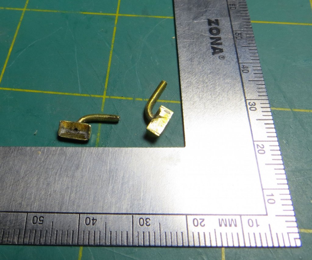
-
Ditto, I have already gained so much from your Naiad books and this log; I look forward to my Christmas present (YA Vols 1 and 2) but, in particular, I am looking forward to the next volume on rigging. cheers Pat
- 3,618 replies
-
- 5
-
-
- young america
- clipper
- (and 1 more)
-
Hi Carl, I have been watching this 'additional' build of yours for a while, but thought I should comment on the great finish you have achieved. A lovely little model. As they look like an elaborate pipe, perhaps on a 'pipe stand' ? cheers Pat
- 46 replies
-
- 6
-
-
- o16
- pacific crossroads
- (and 2 more)
-
Third time lucky; it does look good Russ, even in 'rough' state. cheers Pat
- 420 replies
-
- 3
-
-
- captain roy
- lugger
- (and 2 more)
-
Glad to hear you were able to resolve it Danny; the model is looking very good. cheers Pat
-
Thanks for the pointer Greg, you are absolutely right - I am even more impressed now! cheers Pat
-
Hi Danny, you will get many conflicting results from google or similar searches as the direction was a design criteria and differed from ship Class to ship Class. Even to this day, ships have different propellor configurations to meet the design requirements, which are determined by the winning bidder/tender (and accepted by the Navy/Company) unless specifically detailed in the tender request/Contract. There are arguments offered about fuel economy versus maneuverability etc etc. for the different configurations. Also, as you have summised you need sufficient flow over the rudders to make them effective. Even with twin rudders, if they were not big enough, or incorrectly placed, they may not have been effective with a particular screw configuration. Unless you can find a contract or authoritative document that states what the configuration was, I would recommend the best way to determine this would be to look at any photos of the screws if any exist. The pitch of the blades (I think they were all fixed pitch in these days) will indicate which way they turned? For the central screw, I would not be surprised if it turned in the same direction as the motor output to minimise gearing and complication. It may also be that this screw was only used if extra/the highest speed was needed. That does not help you determine the direction, but apart from the pitch, if you know the motor/engine type, it may be possible to trace that back as well to find it's mechanical properties ..... I would be very surprised that a ship of this fame did not have propulsion information, including about the screws, published about it somewhere. cheers Pat
-
ancre Chebece 1750 by Jeronimo - FINISHED
BANYAN replied to Jeronimo's topic in - Build logs for subjects built 1501 - 1750
Great finish Karl - you never disappoint with the quality of your work. cheers Pat -
Nice work on the hull Dan, looks very good. cheers Pat
- 287 replies
-
- 2
-
-
- michelangelo
- ocean liner
- (and 1 more)
-
Hi Eberhard, thanks for your comments, and yep they come in various guises and brands. I have three different sizes with the larger ones used for shrouds and the like. Not sure of the brand name of mine but they were relatively cheap to acquire from the local electronics store - I think the smaller ones are used for testing circuit boards and the like. Sure are a lot cheaper on eBay :). cheers Pat
-
Good idea with that jig Dave; but what a glutton for punishment doing it the 'real' way with those loops etc at that scale - good luck cheers Pat
-
Fantastic detail and superb metal work. How do you form those gudgeons to have such clean and sharp angles? Do you file them from a solid piece? cheers Pat
-
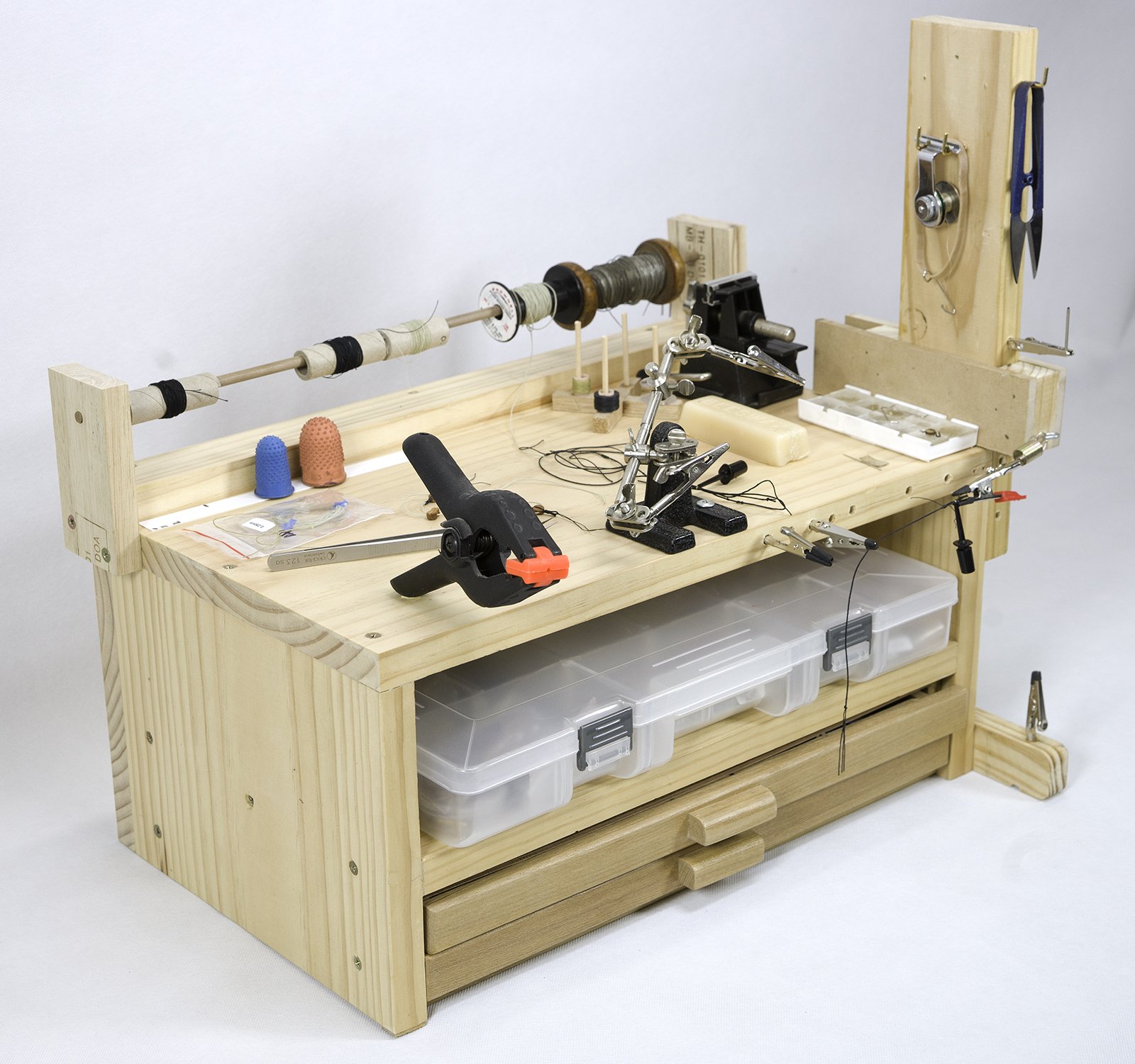
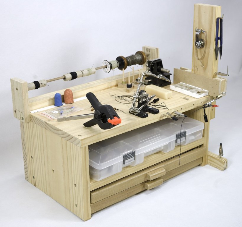
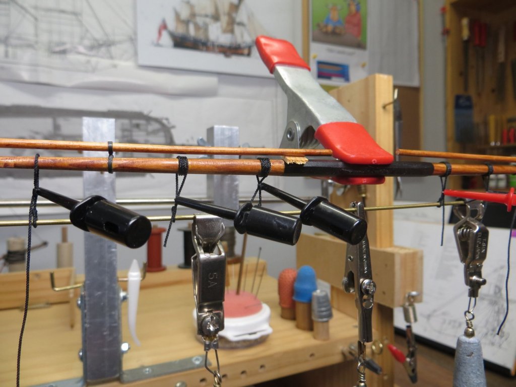
Hi Mike, as per Jud and I tend to rig mine off the model first using the vertical (adjustable) part of my rigging station shown below. i adjust this to the right distance apart (just longer than needed), clip the hooks into the alligator clamps (with both block facing the same way - end on or side on) and rig it here before transferring to the ship. If two single blocks, start with the rigging line attached to the heel of the upper block, run to bottom block threading from front to back, up to the top block threading back to front then down to the bottom block. Cut the running end allowing enough to form several loops or coils after belaying. Use a micro clip (see other photo - available from electronics stores) to temp hold the running end to the other parts of the tackle lines. The trick is to ensure you do not twist this setup during transfer This station (rigging crab) is based on one designed by the late Hubert Sicard (Wooden Ship Modelling for Dummies). I hope that helps?
-
Great techniques Ed. You have accomplished quite some detail with the parcelling and serving at such a scale - the result is excellent. cheers Pat
- 3,618 replies
-
- 5
-
-
- young america
- clipper
- (and 1 more)
-
Steven, try electronics stores for the isopropanol here; the techies use it with their electronics projects apparently. i got some from there in a spray can as well as solution. cheers Pat
-
Perseverance + attitude + problem solving = solution Great result Dan. cheers Pat
- 287 replies
-
- 5
-
-
- michelangelo
- ocean liner
- (and 1 more)
-
Very nicely faired hull Gaetan; you must be happy to moving onto new tasks cheers Pat