BANYAN
-
Posts
5,965 -
Joined
-
Last visited
Content Type
Profiles
Forums
Gallery
Events
Everything posted by BANYAN
-
 The rising of the dead I look forward to the revived build Ben cheers Pat
 -
Nice work especially at that scale Danny. You must have a 'surgeons' hands cheers Pat
- 524 replies
-
- 10
-

-
So distracted again Denis I hope you get back to finish her as she will make a nicely displayed model. Have fun with your Constitution. cheers Pat
- 453 replies
-
- 5
-
-
- thermopylae
- sergal
- (and 1 more)
-
HMCSS Victoria 1855 by BANYAN - 1:72
BANYAN replied to BANYAN's topic in - Build logs for subjects built 1851 - 1900
Thanks Eberhard, that is a very interesting observation about 'shipyard' support and well worth me remembering for some other equipment selections. The 'Victoria' being built by a commercial yard and not for Admiralty, although to RN standards, allowed significant departure from many of the 'current' practices and fit in RN ships of that era. Based on the evidence above, I think I will go with the non-aligned chainplates as depicted. cheers Pat- 1,021 replies
-
- 3
-
-
- gun dispatch vessel
- victoria
- (and 2 more)
-
ancre Chebece 1750 by Jeronimo - FINISHED
BANYAN replied to Jeronimo's topic in - Build logs for subjects built 1501 - 1750
Simply stunning detail and very clean work yet again. cheers Pat -
Very nice technique; well executed Ed. cheers Pat
- 3,618 replies
-
- 3
-
-
- young america
- clipper
- (and 1 more)
-
HMCSS Victoria 1855 by BANYAN - 1:72
BANYAN replied to BANYAN's topic in - Build logs for subjects built 1851 - 1900
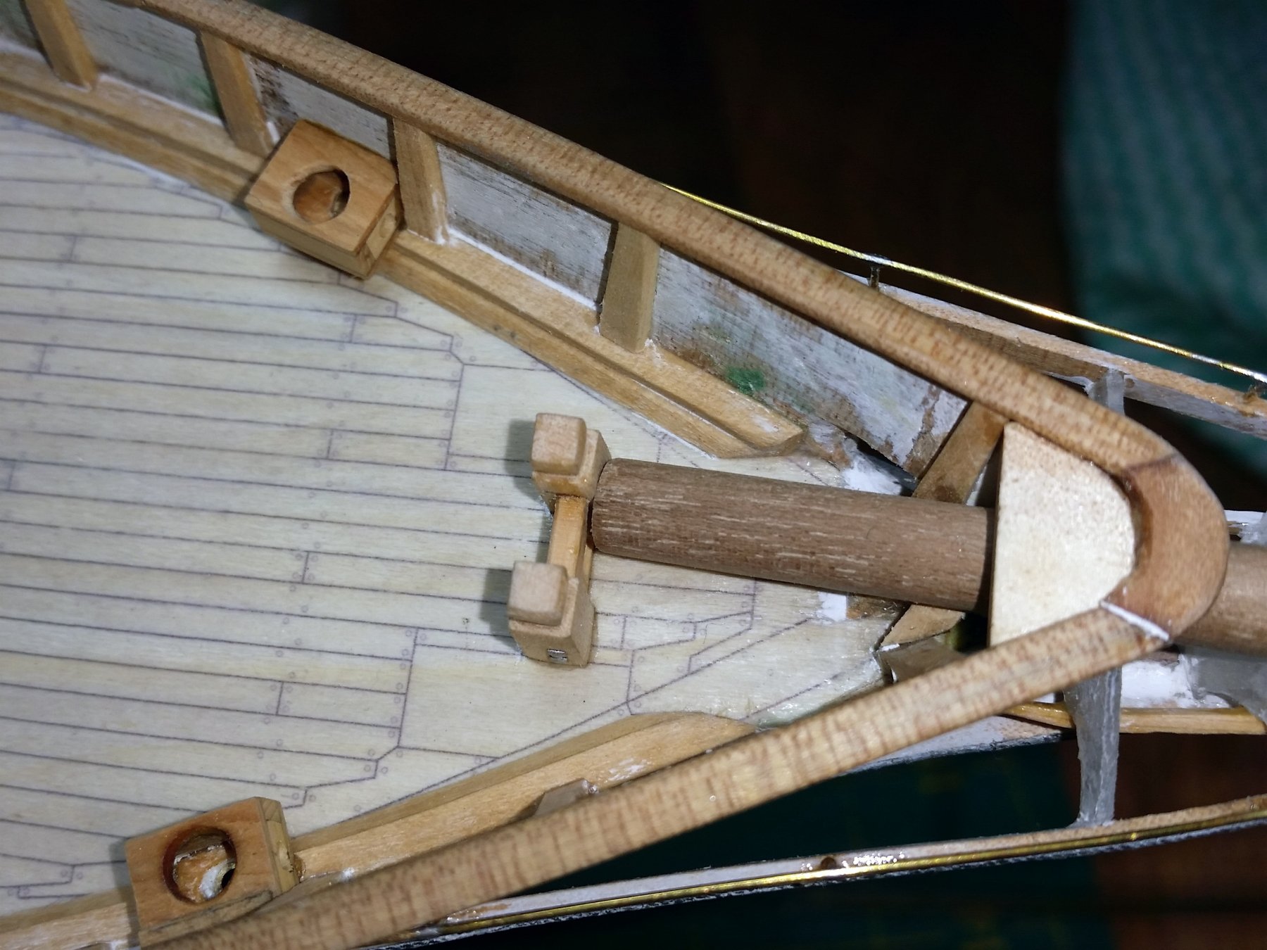
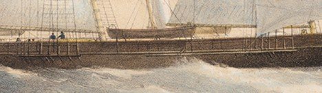
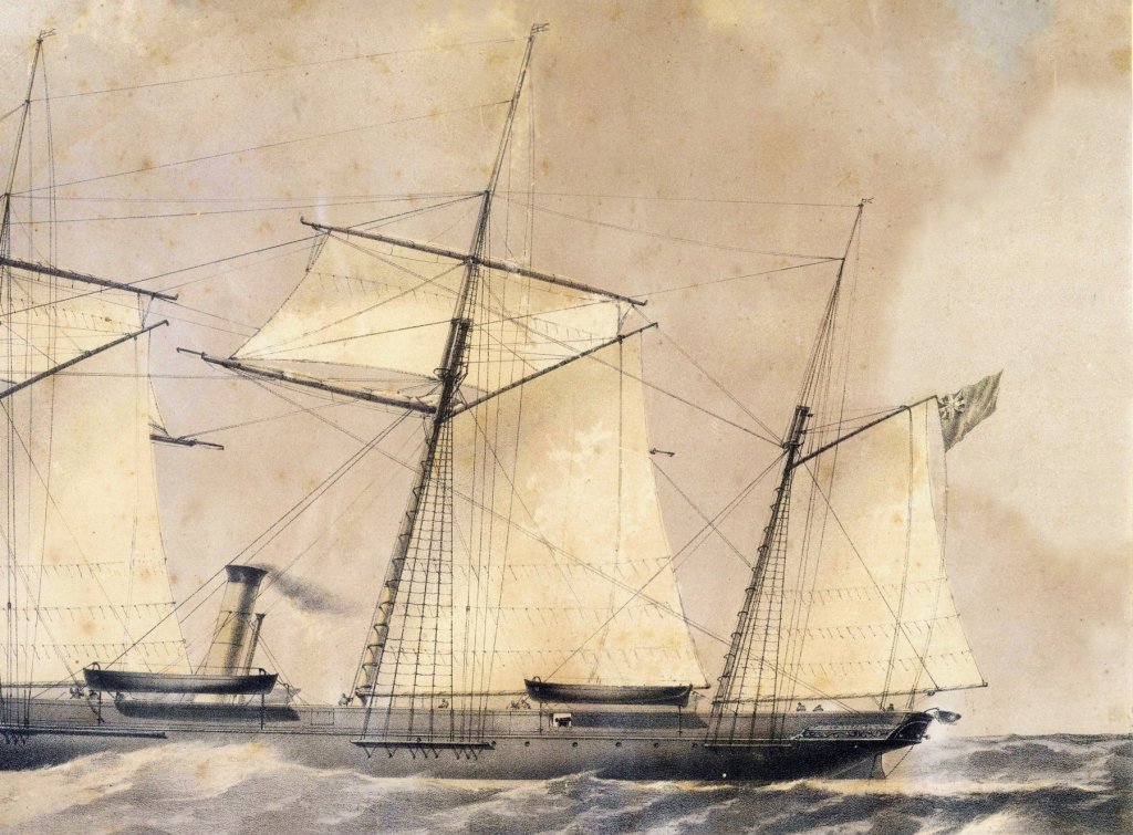
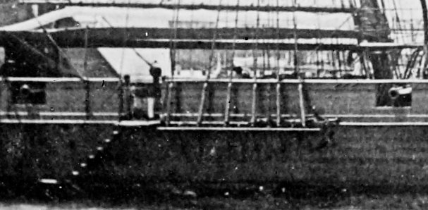
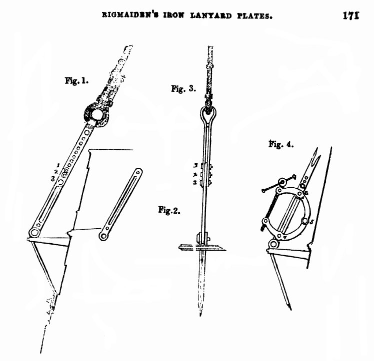
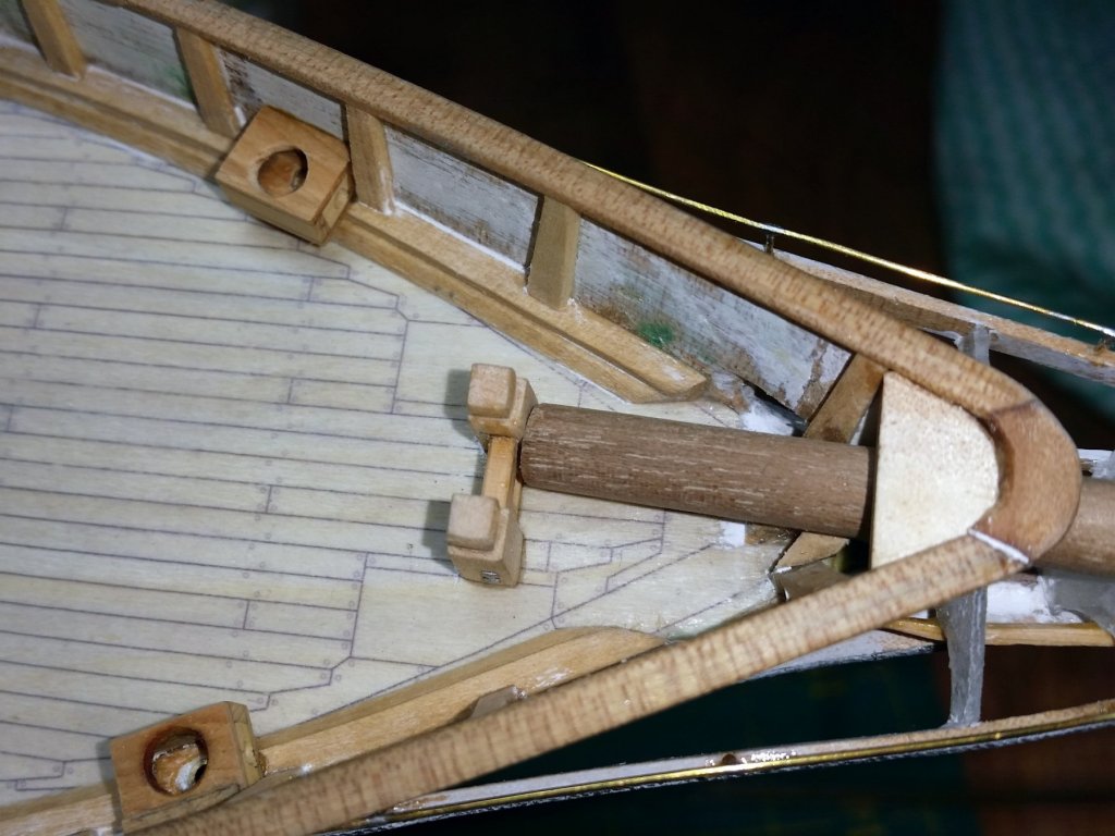
Another small conundrum to resolve before I finalise the rigmaiden lanyards (see last image - From The Mechanics Magazine - out of copyright). Whereas in most earlier sailing ships using deadeyes and rope lanyards, the chainplates conform/align with the angle of the shroud the associated plate attaches to at the channel. From what I can see in the following photo (one marked up, the other as is for verification of detail) and the two lithograph details (curtesy of the State Library of Victoria), it appears that the chainplates on Victoria were simply at right angles to the channel and hull when looking straight a them (still bent to get the right angles to approach the hull when looking fore-and-aft). cheers Pat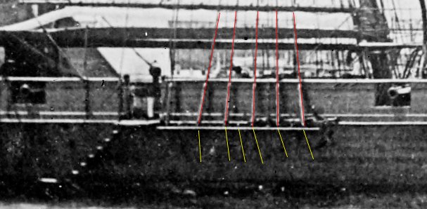
- 1,021 replies
-
- 9
-
-
- gun dispatch vessel
- victoria
- (and 2 more)
-
HMCSS Victoria 1855 by BANYAN - 1:72
BANYAN replied to BANYAN's topic in - Build logs for subjects built 1851 - 1900
Thanks for looking in and kind comments John and Dave. Alas, the cable is a bought aftermarket; not to that ability yet. It is 0.25mm oversize, but smallest I can find. cheers Pat- 1,021 replies
-
- 2
-
-
- gun dispatch vessel
- victoria
- (and 2 more)
-
HMCSS Victoria 1855 by BANYAN - 1:72
BANYAN replied to BANYAN's topic in - Build logs for subjects built 1851 - 1900
Thanks Russ, Carl and Denis - appreciate the support. Off to progress the rigmaiden lanyards - only 36 to do - ugh! cheers Pat- 1,021 replies
-
- 3
-
-
- gun dispatch vessel
- victoria
- (and 2 more)
-
HMCSS Victoria 1855 by BANYAN - 1:72
BANYAN replied to BANYAN's topic in - Build logs for subjects built 1851 - 1900
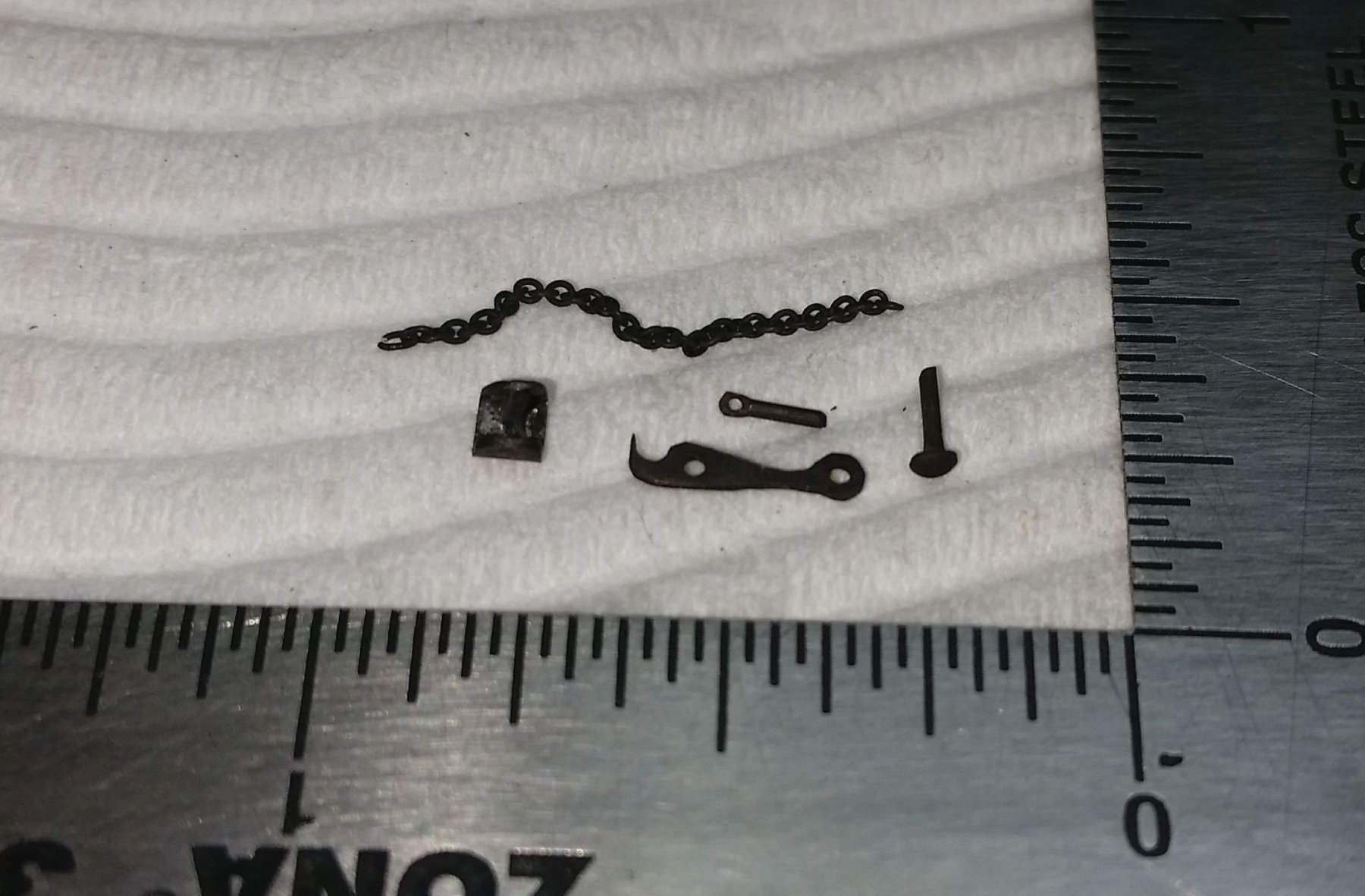
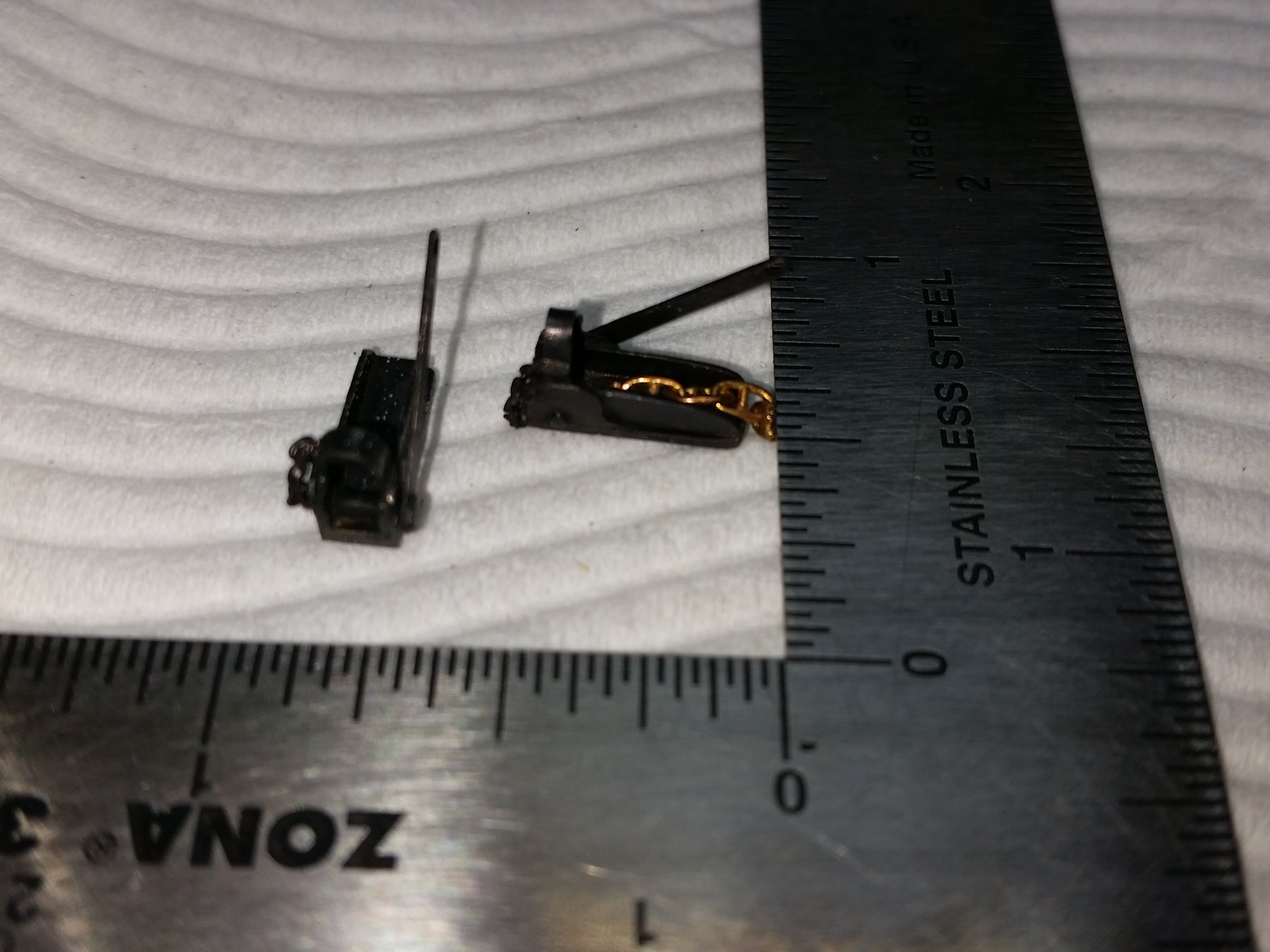
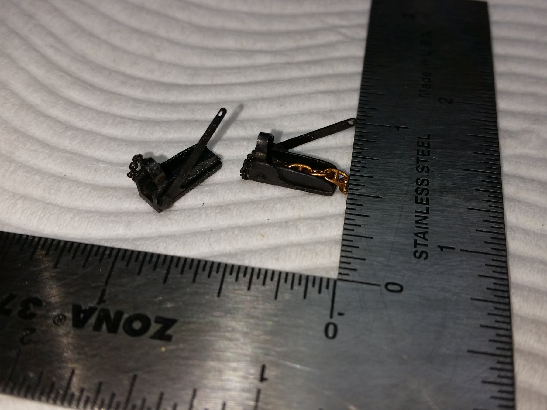
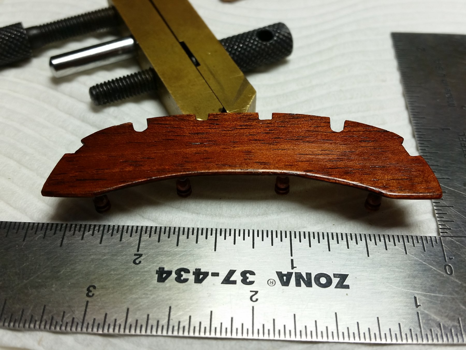
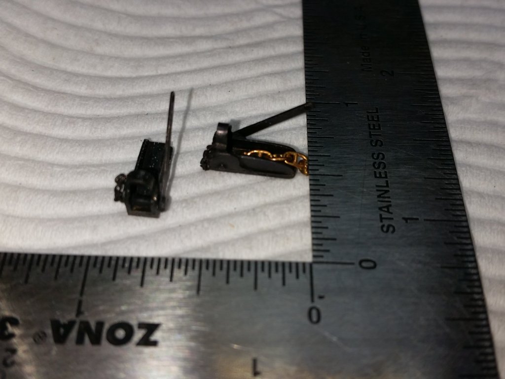
Hi folks, Work to progress all the parts that need to prepositioned or prepared prior to painting continues. I have been working on: the common Service Lifebuoy for the stern, started on the rigmaiden lanyards (these are used in lieu of the rope lanyards and deadeyes), refined the anchor release mechanism parts, the stern bench, the cable stoppers are finished, and I have fitted the heads (lids still to be fitted) - these align with the discharge pipes in the earlier photo to which a canvas hose was fitted to keep the sides clean. The Common Service Lifebuoy had two vertical rails on the stern which, when released, the buoy would slide down; at the same time smoke/flare in the top part would also be ignited by a gunlock. The weight at the bottom would pull down a rod telescoped into the vertical tube which would act as a keel for the two 16 inch (real life) copper balls and keep the flare/smoke vertical to the water. The buoy hung from the stern on the vertical rails by a small chain (just visible in the photo). I now have to predrill the four holes for the rods before painting. One standoff rod is slightly bent at the moment but easily fixed. Most of these parts are very small with the camera being very close it shows all the tiny imperfections just not visible normally - that is an inch ruler in the photos. I will be able to start painting very soon I hope. cheers Pat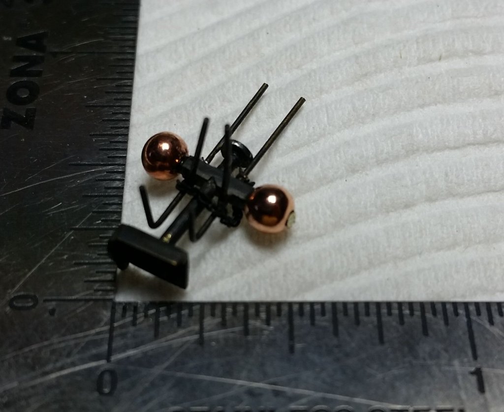


- 1,021 replies
-
- 11
-
-
- gun dispatch vessel
- victoria
- (and 2 more)
-
ancre Chebece 1750 by Jeronimo - FINISHED
BANYAN replied to Jeronimo's topic in - Build logs for subjects built 1501 - 1750
All I can say is: STUNNING - I wish I could add multiple 'thumbs up' cheers Pat -
Looks good in the photo Charlie; but the real test is whether you like it As to the tarp, that is one option I think, not sure if they may have used a lead 'flashing' in a grating. Only problem is that the heat from the "charlie noble' (funnel) may have ignited a tarp covering that was so cl;ose? cheers Pat
- 31 replies
-
- 2
-
-
- ventilator
- flue
- (and 4 more)
-
That is a particularly nice painting Jim; you have a great ability to convey the atmosphere of the scenes you portray! cheers Pat
-
Amazing detail Ed, and again very useful to me. That is a great way to mass produce these parts. I cannot wait for you to publish the third volume cheers Pat
- 3,618 replies
-
- 4
-
-
- young america
- clipper
- (and 1 more)
-
Thanks, it appears I put too much trust in the first converter Google suggested. You are right - worth considerable consideration me theinks cheers Pat
-
Your hands are probably working autonomously by now with muscle memory well and truly established - had enough yet? They look great Dave, some lovely detail on your model. cheers Pat
-
Seems the price may have gone up? I enquired today and A$130 (¥3,700 with postage) is just a little too rich no matter how good the saw. cheers Pat
-
Hi Charlie, what material was used? I had a model printed in 1:350 and it has amazing detail for its size. If I recall mine was printed with the Ultra Frosted stuff. cheers Pat
- 31 replies
-
- 2
-
-
- ventilator
- flue
- (and 4 more)
-
Some more gems, thanks Jim. I note you depict HMAS Melbourne with the LWO2 radar update (LWO4 aerial); when were you aboard? I served in her also and paid her off. cheers Pat
-
Very nice metal work Ed; thanks for the piccy and discussion re 'peening', which will be very useful. cheers Pat
- 3,618 replies
-
- 3
-
-
- young america
- clipper
- (and 1 more)
-
I have not seen one of that shape during my searches Charlie; I wish you luck. Have you considered making one? Seems like a bit of suitably sized brass tube cut cleanly at 45 degrees then soldered to form the 90-degree angle would make the main part. Simply find some conical shape in any material/medium, drill out and slide over the base - paint it black and hey presto cheers Pat
- 31 replies
-
- 4
-
-
- ventilator
- flue
- (and 4 more)
-
Nice work on the forecastle fittings Dan, she is really taking on her finery now! cheers Pat
- 287 replies
-
- 3
-
-
- michelangelo
- ocean liner
- (and 1 more)
-
Nice work Rusty; the detail on that lower sling is stunning. cheers Pat
- 310 replies
-
- 3
-
-
- cheerful
- Syren Ship Model Company
- (and 1 more)