


BANYAN
-
Posts
5,957 -
Joined
-
Last visited
Content Type
Profiles
Forums
Gallery
Events
Everything posted by BANYAN
-
 Coming on nicely Ben, seems like you have the 'paws' of approval cheers Pat
 -
HMCSS Victoria 1855 by BANYAN - 1:72
BANYAN replied to BANYAN's topic in - Build logs for subjects built 1851 - 1900
Hi Carl, thanks for the suggestion. I had thought of that option also, but that means the brass stock would need to be extra thick as the part that slips between the upper part sides is the same thickness as the straps themselves. I think it may be easier (and cheaper) to simply slip a piece in and solder both sides? I am still open to this idea though as it is the simplest, but I think I would need stock 2 x thickness just for these small bits to be part of the etch on one side of the total strip? The fold itself should be straightforward as I can bend it around a drill bit or the like (as a mandrel) but I like the idea of the fold creases being etched in to ensure consistent bending points and size. cheers Pat- 1,013 replies
-
- 2
-

-
- gun dispatch vessel
- victoria
- (and 2 more)
-
Nicely detailed work Jason; everything fits well and looks great. cheers Pat
-
HMCSS Victoria 1855 by BANYAN - 1:72
BANYAN replied to BANYAN's topic in - Build logs for subjects built 1851 - 1900
Hi Carl, Eberhard and Denis; thanks for all the great feedback and discussion. Denis, I have found the correct size brass plate/strip at 1.5mm wide. The total length is 9mm per item (upper and lower) so it would be very difficult (for me at least) to set these up in a mill and consistently replicate the small holes and slots exactly. A special jig/holding tool would be required and I do not have those manufacturing skills unfortunately Carl and Eberhard; I agree fully. The plan is to have the bottom part done as a single etched piece as it is just three holes and a slot. I have to toyed with options for the upper strap which is a little more complicated as it is a series of holes and an eye formed by folding the strap over on itself using a former to bulge it a little. This is the preferred way, as you have also observed, by etching on thinner stock then folding it. My biggest problem here is that I would need to create and fit a very small bolt in the middle to join the two parts together and I am not sure how to achieve that yet. The other option of etching it as a complete piece (both joined) will be much more difficult as you have pointed out, but we are exploring whether or not it is possible. I have to find someone that can do the photoetch first as all known sources here in Australia have shut their shop Eberhard, that is an interesting technique of soldering and I would like to explore that further. What is tinning solution please? I have tinned by soldering onto the surface of one side, then use heat transfer on the outer side of the other piece to join the other part to it - is that what you mean? With the folded strap option, I need to fit a very small spacer at the base of the eye (bottom of the throat) to maintain equal spacing of the straps with the gap formed by joining to the lower part (hope that makes sense) which would be the only soldering required? Light bulb moment - If the etch of the upper strap, when folded, gave the impression of the bolt head one side, and washer and nut on the other, then I could solder the two parts together even if I lose the flexibility of the joint (I still have the flex-joint where it joins with the chainplate) - glad you resolved that for me cheers Pat- 1,013 replies
-
- 2
-
-
- gun dispatch vessel
- victoria
- (and 2 more)
-
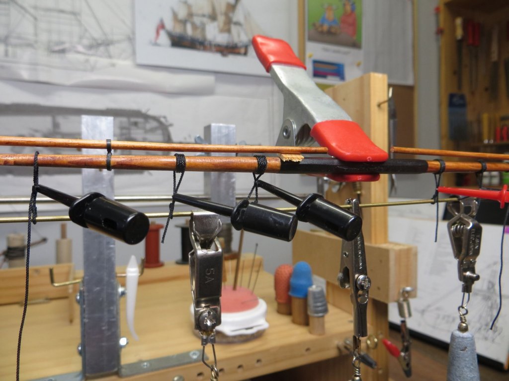
Hi Ed, with my limited experience and talent I am a little reluctant to suggest something but here goes For my Endeavour, I had some success in using diluted PVA (coloured would be better) and weights on a brass rod I had threaded through the lower eyes. the micro clips held the stirrup lashings around the yard in place (undisturbed as you suggest) until completely dry. I then threaded the footrope through having completed the outer eye and seizing beforehand. I then used the same micro clips hanging in the middle of each section to create the catenary by simple gravity. It worked for me but, I found I had to readjust the footropes again at the end as other work does upset them. Food for thought at least? cheers Pat
- 3,618 replies
-
- 10
-
-
- young america
- clipper
- (and 1 more)
-
Some well-deserved self-congratulations are in order Rusty; that is a very fine build. You have done justice to Chuck's products. cheers Pat
- 310 replies
-
- 2
-
-
- cheerful
- Syren Ship Model Company
- (and 1 more)
-
Some more very nice artwork Jim. I love ships from the era of 'great change' where sail was giving way to steam; you have captured that nicely. cheers Pat
-
HMCSS Victoria 1855 by BANYAN - 1:72
BANYAN replied to BANYAN's topic in - Build logs for subjects built 1851 - 1900
Hi Denis, great to hear from you again and your thoughts on the lanyard tensioning device. I have thought about that quite a bit and raised it with club members. A group discussion came to the consensus, that as the ship was minimum manned (as per a merchantman rather than a warship), it is unlikely they would have the manpower to adjust more than one or two shrouds at a time (in pairs). As such it was decided that she probably only had a couple of them, with one or two as spares. The thought was these were probably kept in the bosun's locker and not exposed to the elements - accordingly we don't plan on making or showing any at all. We also need to consider that the shrouds were 'wire rope' which is not prone to stretching, and as the lanyards were metal also, once set up, there probably was not a great need to adjust them like rope lanyards? The lanyards will be made in two parts, and attach at the channels to the plates as a swivel. I have tried making these on the mill but the brass bar/strip is so small it is difficult to achieve consistent results (with my limited skills anyway) - so we are looking for somewhere to have them done as Photo Etch. We haven't been able to find anyone in Australia so I will be searching for a source overseas very soon. The required detail to etch from both sides will need a specialist I think as it is not a simple etch process I could do at home. cheers Pat- 1,013 replies
-
- 2
-
-
- gun dispatch vessel
- victoria
- (and 2 more)
-
That is amazingly neat and very detailed work ED; I learn so much from watching (and reading) your techniques. It is not so easy to turn it into practice though cheers Pat
- 3,618 replies
-
- 5
-
-
- young america
- clipper
- (and 1 more)
-
Nice work Dave, those ratlines look very 'smick' Congrats on your son's achievements. cheers Pat
-
You're making good progress OC; I had missed your latest log - I hope there is still some room in the stalls cheers Pat
- 455 replies
-
- 4
-
-
- slightly modified
- greyhound
- (and 1 more)
-
Can't have that mate; the dead would never get to their resting place Look forward to seeing it come alive )so to speak). cheers Pat
-
What a way to dazzle your dinner guests - if you would trust them using these beautiful works of art. cheers Pat
-
Very nice work Danny; I keep forgetting how small and fiddly these parts are. cheers Pat
-
Lovely Rusty, a very nicely built model. cheers Pat
- 310 replies
-
- 2
-
-
- cheerful
- Syren Ship Model Company
- (and 1 more)
-
The rising of the dead I look forward to the revived build Ben cheers Pat
-
Nice work especially at that scale Danny. You must have a 'surgeons' hands cheers Pat
- 524 replies
-
- 10
-
-
So distracted again Denis I hope you get back to finish her as she will make a nicely displayed model. Have fun with your Constitution. cheers Pat
- 453 replies
-
- 5
-
-
- thermopylae
- sergal
- (and 1 more)
-
HMCSS Victoria 1855 by BANYAN - 1:72
BANYAN replied to BANYAN's topic in - Build logs for subjects built 1851 - 1900
Thanks Eberhard, that is a very interesting observation about 'shipyard' support and well worth me remembering for some other equipment selections. The 'Victoria' being built by a commercial yard and not for Admiralty, although to RN standards, allowed significant departure from many of the 'current' practices and fit in RN ships of that era. Based on the evidence above, I think I will go with the non-aligned chainplates as depicted. cheers Pat- 1,013 replies
-
- 3
-
-
- gun dispatch vessel
- victoria
- (and 2 more)
-
ancre Chebece 1750 by Jeronimo - FINISHED
BANYAN replied to Jeronimo's topic in - Build logs for subjects built 1501 - 1750
Simply stunning detail and very clean work yet again. cheers Pat -
Very nice technique; well executed Ed. cheers Pat
- 3,618 replies
-
- 3
-
-
- young america
- clipper
- (and 1 more)
-
HMCSS Victoria 1855 by BANYAN - 1:72
BANYAN replied to BANYAN's topic in - Build logs for subjects built 1851 - 1900
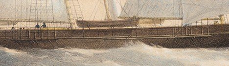
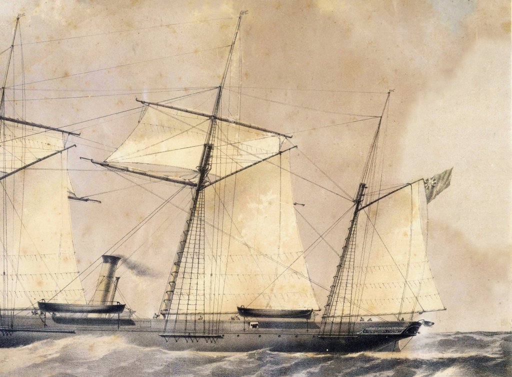
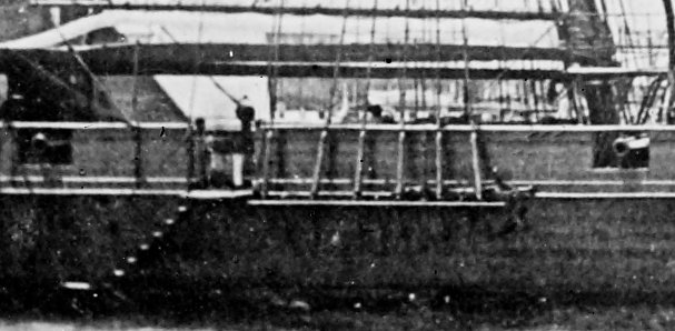
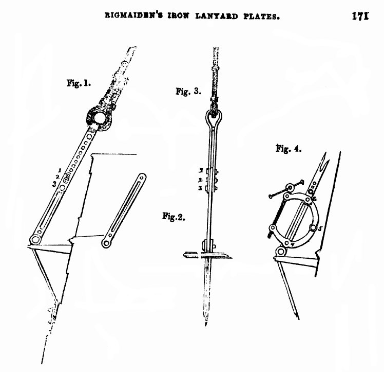
Another small conundrum to resolve before I finalise the rigmaiden lanyards (see last image - From The Mechanics Magazine - out of copyright). Whereas in most earlier sailing ships using deadeyes and rope lanyards, the chainplates conform/align with the angle of the shroud the associated plate attaches to at the channel. From what I can see in the following photo (one marked up, the other as is for verification of detail) and the two lithograph details (curtesy of the State Library of Victoria), it appears that the chainplates on Victoria were simply at right angles to the channel and hull when looking straight a them (still bent to get the right angles to approach the hull when looking fore-and-aft). cheers Pat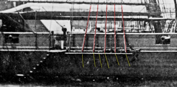
- 1,013 replies
-
- 9
-
-
- gun dispatch vessel
- victoria
- (and 2 more)
-
HMCSS Victoria 1855 by BANYAN - 1:72
BANYAN replied to BANYAN's topic in - Build logs for subjects built 1851 - 1900
Thanks for looking in and kind comments John and Dave. Alas, the cable is a bought aftermarket; not to that ability yet. It is 0.25mm oversize, but smallest I can find. cheers Pat- 1,013 replies
-
- 2
-
-
- gun dispatch vessel
- victoria
- (and 2 more)

