HOLIDAY DONATION DRIVE - SUPPORT MSW - DO YOUR PART TO KEEP THIS GREAT FORUM GOING! (Only 69 donations so far out of 49,000 members - Can we at least get 100? C'mon guys!)
×


BANYAN
-
Posts
5,946 -
Joined
-
Last visited
Content Type
Profiles
Forums
Gallery
Events
Everything posted by BANYAN
-
 I have been on holiday and only just found your wonderful build Druxey; add me to the list of enthusiastic followers. A great subject for a model also. cheers Pat
- 641 replies
-
- 4
-

-
- greenwich hospital
- barge
- (and 1 more)
-
Great progrees Dave, and glad to see you have very quickly come to grips with resistance soldering - it's the ant's pants once you work out the right power settings for the various types of jobs cheers Pat
-
Looks great Ron - hope you're back in your new digs soonest with no more major rumbles.
-
Somevery nice detail emerging Dave; will really add to the model presentation when complete. cheers Pat
-
Swee-eet work Danny, looking very good. Great to hear you will be back in your 'office' again mate; must have been a real pain with all that moving. Impressed that you have been able to achieve what you have given the circumstances. cheers Pat
-
Removing Blacken-It from Brass
BANYAN replied to mtaylor's topic in Metal Work, Soldering and Metal Fittings
Mark, try rubbing with a fibreglass pencil brush then soaking them in Muriatic (brickies) acid for a while. I was able to use this method with a bit of scrubbing with a toothbrush to remove some blackening (I used Birchwood Casey blackener) which had not worked so well in parts. This got them back to near clear brass but it certainly was not as shiny a surface but a scrub with fine steel wool certainly resolved that Please note this was not a deep blacken process as I notice the mottled effect before the full process had not completed. cheers Pat -
Go on Chris take the challenge (says me who only trenneled the deck planks) Nice progress cheers Pat
-
Make sure to drop in on Melbourne while you're here Mark cheers Pat
- 745 replies
-
- 3
-
-
- francis pritt
- mission ship
- (and 1 more)
-
Great to see some progress mate - will be great to see your build underway again, Really frustrating when you can't get getthe rightbits of materials huh? You may have to setup your own shop Dennis cheers Pat
-
Looking really neat Jason; you seem to be overcoming all the challenges being presented. cheers Pat
-
Some nice additions to your little lady John; she is starting to get her Character now. cheers Pat
- 745 replies
-
- 4
-
-
- francis pritt
- mission ship
- (and 1 more)
-
Keep on rattlin mate; you'll get there Love the effect you have created on the lines (close-ups) which reallygive the effect of grease heavy (tarred) lines. cheers Pat
-
Nice work Ian. I am doing these at the moment also (well finish when I get back from holiday ) and your method for the ball/knob on the end of the aiming arm will help me greatly - thanks for sharing. cheers Pat
-
Looking good Chris Pat
-
Nice save mate, they look good especially considering the scale. Pity about the attitude from Eduard - I won't purchase anything from them if that is the way they treat customers when it is their problem Question: How do you glue your stanchions, especially the singles - both glue & jigs to get them to stay in place and look perfectly aligned from the horizontal and vertical perspectives - and get them to stay there? [Edit - I realise that these ones still have the base fret attached, I am assuming you have done singles as well where required? The type of glue is applicable to all please] cheers Pat
-
Welcome back mate; she is coming along very nicely (pity my spelling isn't - fixed in edit). You'll have to bring her along to a meeting again soon (I won't be at the next one - travelling). cheers Pat
-
My of my John, she is really looking a treat. cheers Pat
- 745 replies
-
- 3
-
-
- francis pritt
- mission ship
- (and 1 more)
-
Thanks all for looking in and kind comments. John, yep - that is the downside as it does cost significantly more to set up. But I would argue that if doing a lot of soldering, and some of that may be on or very near the model at times (fixing breakages etc ) then it is still a WHOLE lot cheaper than rebuying/redoing the model if it catches fire The real advantage though is that I can do several different joints in very close proximity without de-soldering the others to get a new one ion place. if you can afford it, I would very highly recommend it. cheers Pat [Edit: I should have been a little clearer that the gun barrels are after-market - these are some of Chuck's excellent products.]
- 517 replies
-
- 3
-
-
- Endeavour
- Artesania Latina
- (and 1 more)
-
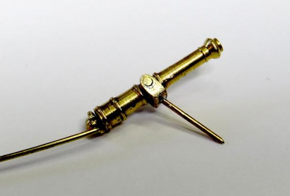
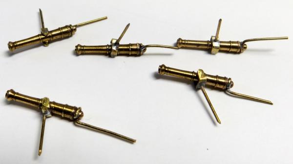
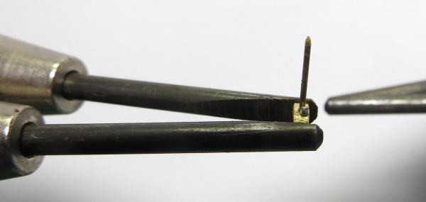
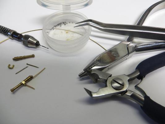
Part 2 of the Swivel gun assembly process with some partially completed units in the last photo. I still need to clean these up, blacken them and add the control arm knob/timber (not sure which way to go yet). I am also looking foe pointers/advice on what to use or how to create a fixed circular pate about half the way down the spigot that would sit on the gun post and stop the spigot going further down the hole. This then allowed to gun to rotate in the hole. This will require a very small washer type part to be soldered in place which at about 1.5mm may be a tad small to achieve cheers Pat
- 517 replies
-
- 11
-
-
- Endeavour
- Artesania Latina
- (and 1 more)
-
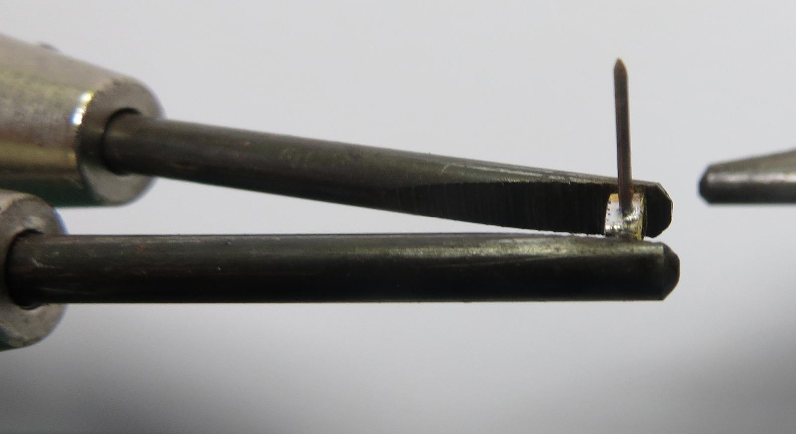
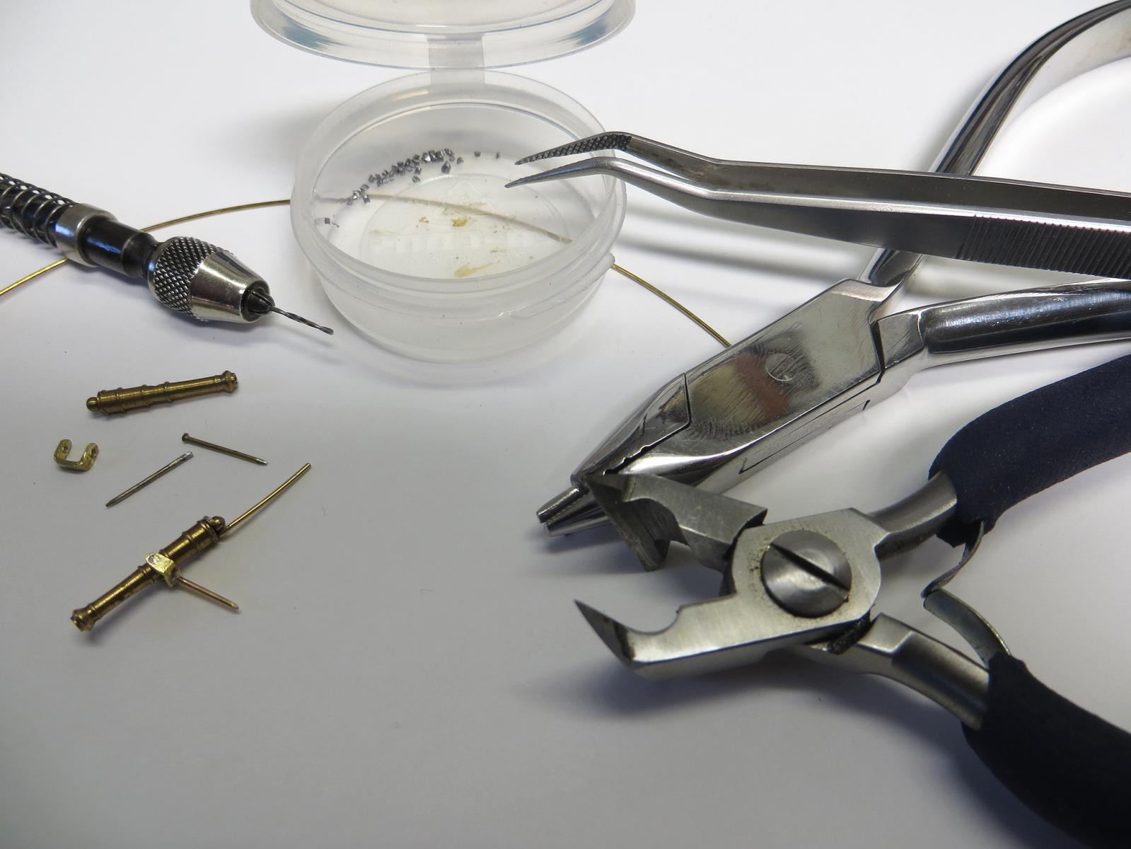
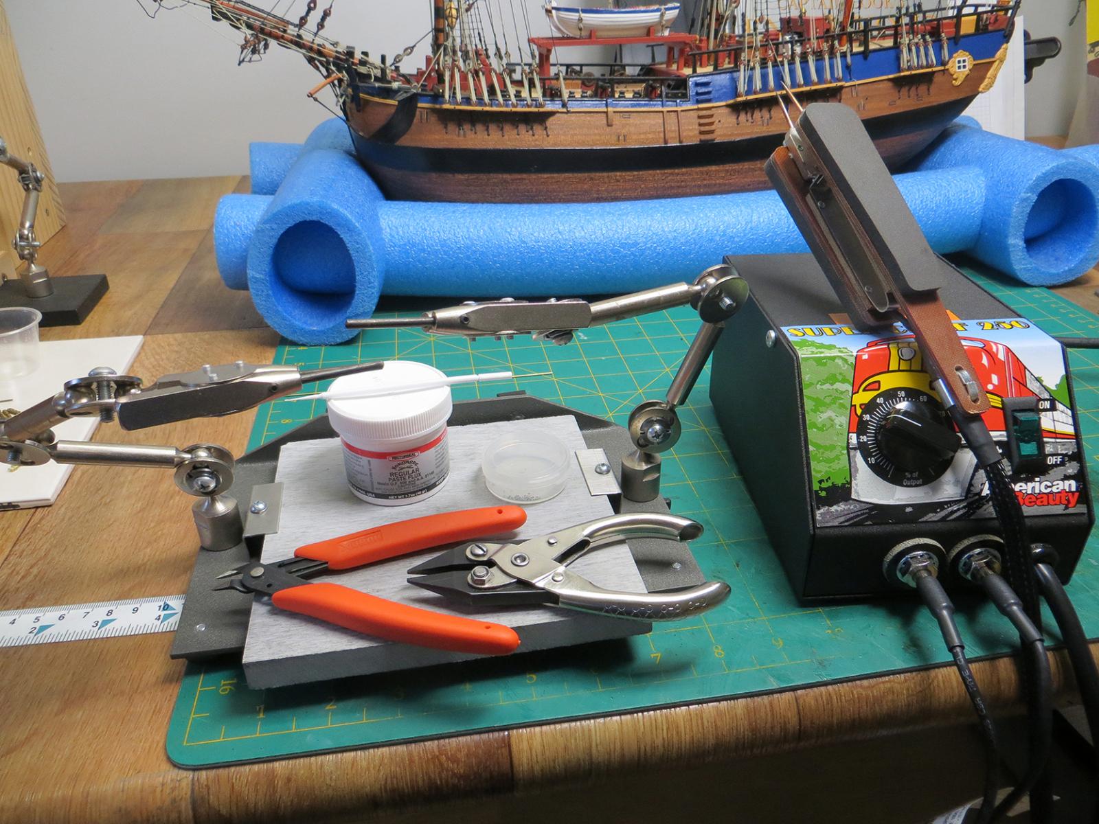
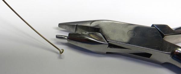
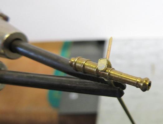
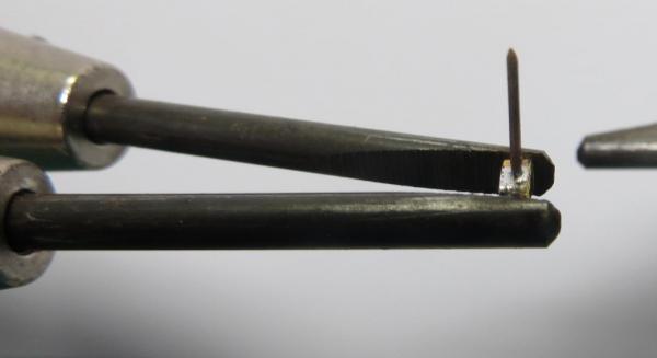
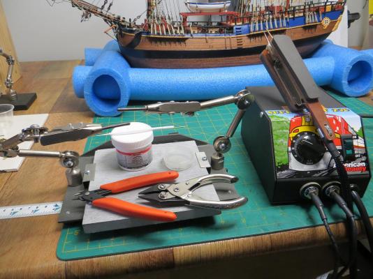
Part 1 of the Swivel Gun production line These show my soldering set-up and some of the tools I use. Also the first stages in preparing and soldering the cradle for the gun - one photo shows the part in place with flux applied and bead of solder ready to for the heat. As you can see a relatively clean joint with minimal clean-up required. Please note the part is only 1.25mm x 4mm long x 3mm high. I have moved to Resistence Soldering as it enables me to really control the soldering heat and restrict the area that is intensely heated for the solder to flow. The anchor ring above was soldered in-situ with the puddenning in place with no problems. this will also allow me to solder chains, plates etc on the model if required; but some care is still required. A lot better than putting a naked flame anywhere near these materials. cheers Pat
- 517 replies
-
- 7
-
-
- Endeavour
- Artesania Latina
- (and 1 more)