HOLIDAY DONATION DRIVE - SUPPORT MSW - DO YOUR PART TO KEEP THIS GREAT FORUM GOING! (Only 69 donations so far out of 49,000 members - Can we at least get 100? C'mon guys!)
×


BANYAN
-
Posts
5,946 -
Joined
-
Last visited
Content Type
Profiles
Forums
Gallery
Events
Everything posted by BANYAN
-
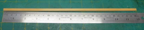
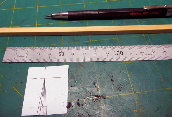
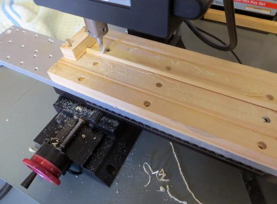
 Hi again folks. I have finally motivated myself to make a start on the yards. The following photos (across two posts) shows the process I have used with two yards now formed. After resizing the plans to suit my scale (1:60) I have printed them to form a guide and from which to take measurements - I double check these against the spreadsheet created by Dan Vad to ensure all is accurate. I then mark up the square stock using the 7:10:7 rule for which I have generated a template on my PC. The square stock is then fitted to the jig for milling into the octogan base yard. The jig and the process, are a modification of that recommended by David Antscherl in his "The Fully Framed Model, ....., Vol 4" - thanks David this Volume has been very useful. Once the octagonal has been formed, I spin the stock in my lathe to shape the tapered and rounded outer yard arms - I use a plastic tick strip as my ready reference. This has proven workable for me with the Main and Fore Main yards now shaped (yet to receive the furniture) - I will make a start on the crossjack this week and then onto the upper yards. cheers Pat
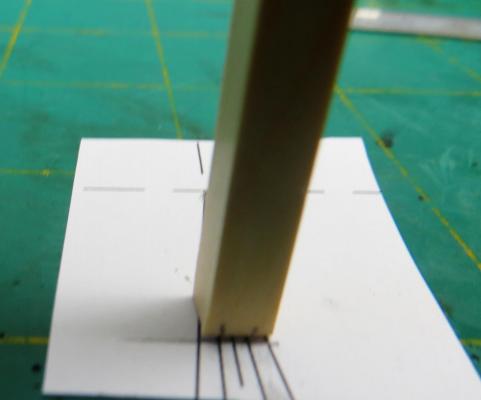
- 517 replies
-
- 12
-

-
- Endeavour
- Artesania Latina
- (and 1 more)
-
You'll have quite the fishing fleet by the end of this process mate and jump over to the MM for a bit of R&R Interesting concept re variations of the same hull base. cheers Pat
-
What an interesting subject for a model. I didn't even know she existed and thought the Japanese subs with their planes were unique (wonder where they got there idea??) cheers Pat
-
Dave, they are looking really good. If you can avoid doing so; I would recommend leaving the channel capping pieces off until you have finished rattlin - that way of any of the joints give way 9like they did for me) at least you won't have to worry about removiong the glued capping piece. maybe a temporary one that is pinned to hold the chains and deadeyes in place? Keep he good work going mate, she is looking great. cheers Pat
-
Exceptional carving mate. cheers Pat
-
Very nice work/progress Ian. Add ne to option 1 also for the rail - looks more natural. cheers Pat
-
I learned that the hard way also Dave. I use Birchwood Casey blackening which works on most soft metals and solders (tin and silver base). It is also easy to touch up on the model if you do happen to damage the finish by using an cotton bud to dab the solution and cleaning off with water. The main items likely to be surface damaged are the nails (bolts) where sometimes a little force is required to drive them fully - but properly sized drilled holes should minimise even this. cheers Pat
-
Thanks everyone for looking in and all the likes - very motivating and rewarding to see the interest. regards Pat
- 517 replies
-
- 4
-
-
- Endeavour
- Artesania Latina
- (and 1 more)
-
Ben, have you checked the "Titan" movies, one of them, clash of the titans I think, incudes a scene of this crossing which may help with ideas. cheers Pat
-
Hi all. I was remiss in not advising that the barrels I used were some of the excellent products offered by Chuck through Syren. makes a big difference to the level of detail. cheers Pat
- 517 replies
-
- 5
-
-
- Endeavour
- Artesania Latina
- (and 1 more)
-
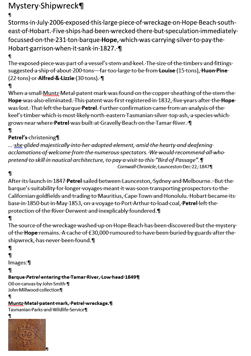
Robin, Druxey, I received the following response (partial text) which I copy below with permission of, and prepared by the Maritime Museum of Tasmania. It seems that further research has ruled out the "Hope" and identified the vessel as a locally built vessel, the "Petrel", which is more contemporary with your suggested period Robin. I hope this helps satisfy some of your curiosity I will ontinue to pursue the "Hope" as this snippet of info has intrigued me now (not the 'silver' as I am not a salvager) but rather what sort of ship she was. cheers Pat
-
Nice start to your build mate; coming along nicely. Sorry I missed your log as i like to follow all Endeavour logs. I'll follow along for a bit . cheers Pat
-
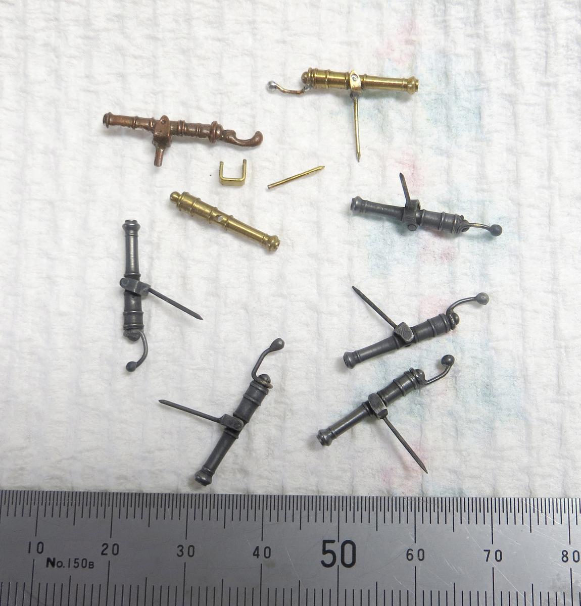
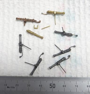
Hi all, a small update to the swivel guns. This shows some of the completed items along with the kit part and some left over parts (errors/badly made) bits left over, but give an idea of the process I followed. Dan, the beauty of resistance soldering is that you have much more control of the heat and soldering the pins on later was not a problem. cheers Pat
- 517 replies
-
- 12
-
-
- Endeavour
- Artesania Latina
- (and 1 more)
-
Rick, There is a replica in Tasmania. If you contact them they may be willing to open a discussion and maybe able to shed some light on your questions? cheers Pat
-
Nah Denis, that model actually looks unsinkable One ship at a time mate; you'll get there; I am sure a delay here or there can be countenanced? cheers Pat
-
Who'se to say whether right or wrong Steve, these design parameters usually morphed over a period of time rather than as a regulated change - they look good. cheers Pat
-
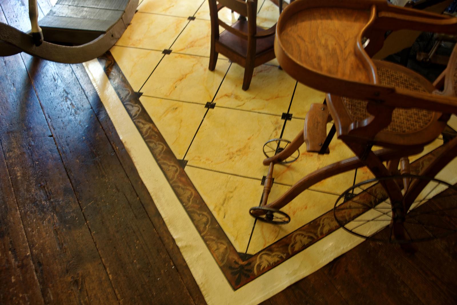
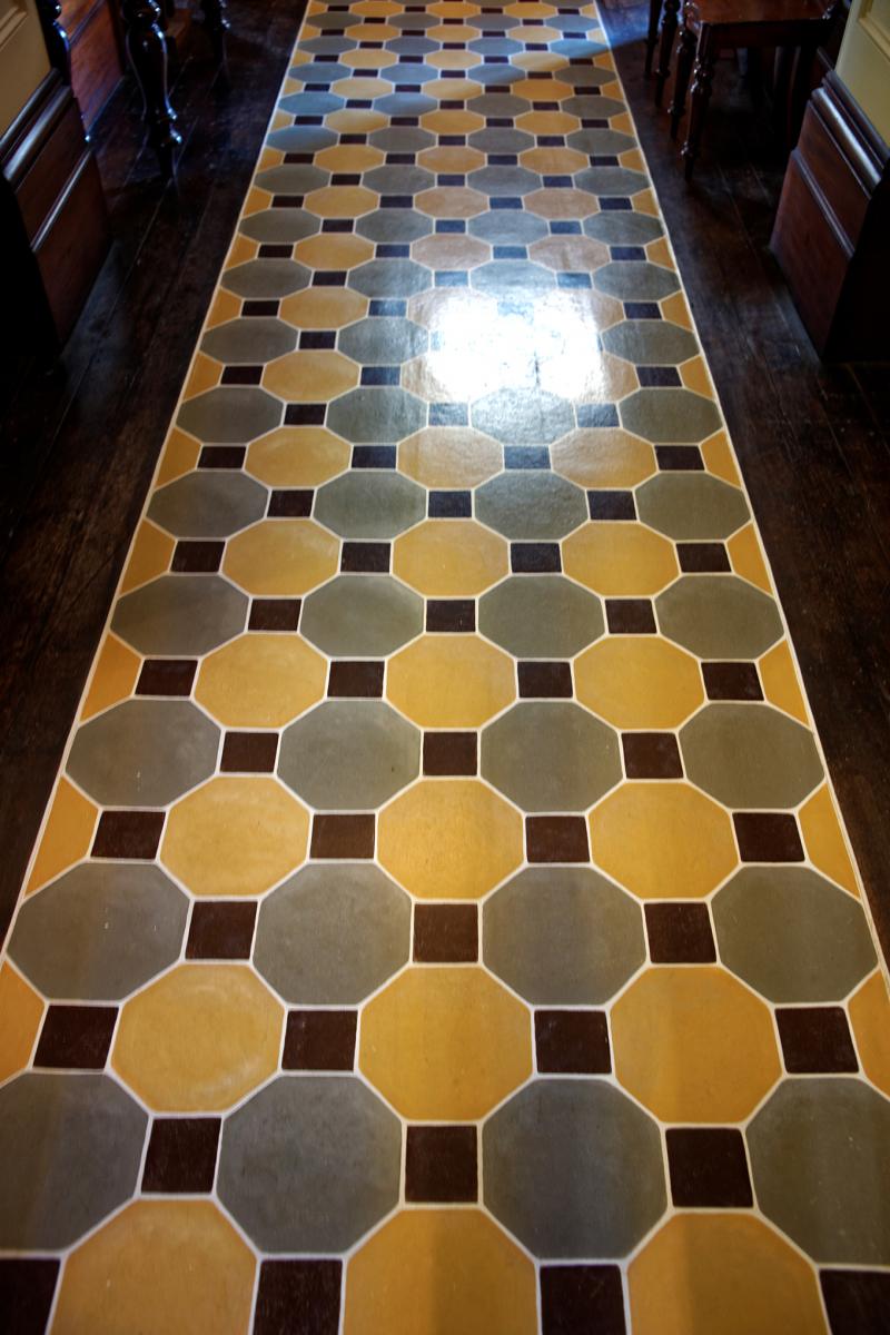
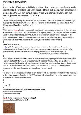
Hi folks, Also on this holiday we took a look in at a National Trust House called Runnymede; which was at one time, the home of a very successful Whaling ship captain and owner of a fleet of whaling ships based in Hobart, Tasmania. In there I found a couple of canvas mats/runners which I believe may have been made exactly like the ones in ships. they show Howell made these were with some very intricate patterns and look quite good. posted for interest. cheers Pat


-
Hi Robin, Here is another pic of this artifact but does not help with any specific information. https://www.expedia.ca/Maritime-Museum-Of-Tasmania-Hobart.d6086805.Vacation-Attraction I'll keep looking around and get back to you if I find something cheers Pat
-
Very nice and precise work Steve. Did you mill or hand cut the sheave holes? cheers Pat
-
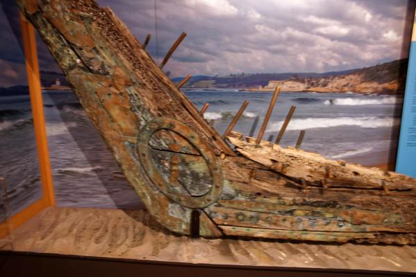
This may not be the best forum for this photo/info - mods please move if required. While on holiday in Tasmania recently I visited the Tasmanian Maritime Museum in Hobart. While small, it had some interesting artifacts including this section of timber from the bow of an unknown vessel believed to be mid-1800s (possibly the Hope). It shows some good exampls of the copper/brass fixings. It is a slightly fuzzy photo as I had to shoot hand held without flash under some very poor lighting. I hope it is of benefit to some members? cheers Pat
- 4 replies
-
- 10
-
-
Man you are a sucker for punishment Greg but those funnels will really look good with the PE. cheers Pat
-
She is looking good Dave; plenty of nice detail. I left the boat boom hardware off the channels as I thought I might catch them and damage them or the channels while rigging; I'll be interested to see how you make out. cheers Pat