BANYAN
-
Posts
5,965 -
Joined
-
Last visited
Content Type
Profiles
Forums
Gallery
Events
Everything posted by BANYAN
-

Understanding Truss Pendants and other rigging things
BANYAN replied to LucienL's topic in Masting, rigging and sails
Hi all, I think that perhaps the make-up of the pendants had begun to change in this era. Certainly the Rigging Warrant for HMCSS Victoria (1855) listed wire mast pendants with thimbles in lieu of blocks. Druxey, sorry, I am not trying to be contentious; I agree blocks had been the usual practice, but I think in the era of chain and wire this may have started to change? cheers Pat -
A few figurehead drawings in a collection compiled/collected by Oliver W Lang unearthed by researcher in the National Archives (UK) (I think?). These were in a box of drawings, sketches etc believed collected by Lang when commissioned to gather information from all Royal Dockyards in the mid-19th century, in an attempt to standardise the way equipment was fitted. cheers Pat Figure Head Drawings from a Package of drawing by Oliver W Lang.pdf
-
Good news Michael, looking forward to seeing you back at the workbench. Best wishes for a full and fast recovery. Pat
-
Very nice work Rob, she is coming along beautifully. cheers Pat
-
HMCSS Victoria 1855 by BANYAN - 1:72
BANYAN replied to BANYAN's topic in - Build logs for subjects built 1851 - 1900
Hi all, many thanks for the likes and comments; they are much appreciated. Tony, I used the thin walled one as its' ID was pretty well right - just need a very small stretch with a mandrel. The mill set-up is all Sherline. The rotary table is actually part of a horizontal indexing accessory bed from which I remove the rotary indexer head and fix it to the mill x-table bed, The drill is fitted into a 'sensitive drilling' accessory which makes life a lot easier. Once I had determined the angular spacing, all became a 'production run'. I am now debating how to create the 'wedges' in the mast collars. My initial thoughts are to use the horizontal indexing accessory mentioned above. The more difficult decision is whether to lightly score them in, or simply mark and draw in with a hard pencil. My worry with scoring them is that I end up snapping/splitting them based on the grain direction. I meant to mention in the earlier post that the lower masts in Victoria were red pine (the upper where needed were yellow pine), so the colour has come up pretty well. cheers Pat- 1,021 replies
-
- 4
-

-
- gun dispatch vessel
- victoria
- (and 2 more)
-
HMCSS Victoria 1855 by BANYAN - 1:72
BANYAN replied to BANYAN's topic in - Build logs for subjects built 1851 - 1900
Hi all, thanks to Tony's generosity I was able to complete the spiderband for the Mizen mast. The dust on the base of the mast is where I was sanding it ready to put on a coat of finish. I think the series of shots posted earlier, along with these are self explanatory as to how I made these. Once the set-up had been worked out it simply became a matter of production line activity. The final photograph is of the masts with their spiderbands and collars (I have yet to simulate the wedge shapes on the collars) cheers Pat
- 1,021 replies
-
- 13
-
-
- gun dispatch vessel
- victoria
- (and 2 more)
-
Not just 'discovered' Ed, but actively being used. The quality of this work and your books will continue to not only be an inspiration, but an essential reference for clipper ships. cheers Pat
- 3,618 replies
-
- 1
-
-
- young america
- clipper
- (and 1 more)
-
You are creating some very nice drawings/sketches ClipperFan. The high level of cooperative input will result in some very accurate renditions. cheers Pat
- 3,560 replies
-
- 3
-
-
- clipper
- hull model
- (and 2 more)
-
Nice work on the planking Mark, slowly but surely will get you there. cheers Pat
-
They look good (no excellent) Rob, I should never have doubted cheers Pat
-
For my tuppence worth, my mantra on this subject is that "there is always more than one way to skin a cat" (sorry cats). All I aim for is that the finished item looks right, and I make use of many 'false' finishes to achieve it Each to their own, and rather than take offence I simply ignore the 'rivet counters'. cheers Pat
-
HMCSS Victoria 1855 by BANYAN - 1:72
BANYAN replied to BANYAN's topic in - Build logs for subjects built 1851 - 1900
Hi guys, thanks for the offers; much appreciated. Rob, speaking for myself, but I am sure many others, are well and truely getting tired of the continuous lockdowns - made all the worse by idiots who will not do a few simple things - only interested in their own interests. Now that our vax levels are getting better we are all hoping to be able to avoid the lockdowns. Online has been OK during the lockdown but some supplies are getting scarce - I have heard a rumour K&S have stopped making some small shapes which may explain why I can't find much. John, thanks for that; certainly a fall back option. Tony, many thanks - much appreciated. I think I can easily stretch the 5.5mm ID tube on a mandrel to make it work; but either would work as I can ream out the thicker walled one. Would greatly appreciate a short length of either. Please let me know costs and postage etc. cheers Pat- 1,021 replies
-
- 4
-
-
- gun dispatch vessel
- victoria
- (and 2 more)
-
A lot of excellent detail there Rob, looks very good - even close up. Are the channels dry fitted? Doing the holes for the deadeye straps/chainplates will be difficult on the model? cheers Pat
-
That is one very fine model Greg - and you are not even finished with it yet. Your best yet I think. cheers Pat
-
HMCSS Victoria 1855 by BANYAN - 1:72
BANYAN replied to BANYAN's topic in - Build logs for subjects built 1851 - 1900
Thanks for the laughs guys; the levity is much appreciated while we are in lockdown Seriously though, back to the product: yep the spacing was out between three of the holes. Greg, I did use a a rotary table for the test piece but I made the error (about half way through) of miscalculation/set-up in only progressing 20 degrees instead of 30 degrees. Shows you really need to concentrate. I am having some difficulty finding the appropriate stock (tube) to use for the mizen mast spiderband. I need brass tube of 5.75mm ID, or something close to it with enough meat in the walls to ream it out a little. I have searched the online stores here in Australia, and some overseas with no luck. Does anyone happen to have a short length of something suitable that I could use? Edit: or point me to somewhere I can et it? cheers Pat- 1,021 replies
-
- 3
-
-
- gun dispatch vessel
- victoria
- (and 2 more)
-
HMCSS Victoria 1855 by BANYAN - 1:72
BANYAN replied to BANYAN's topic in - Build logs for subjects built 1851 - 1900
...and here I was thinking it was a band of spiders (mates to those guys that do rigging) cheers Pat- 1,021 replies
-
- 4
-
-

-
- gun dispatch vessel
- victoria
- (and 2 more)
-
HMCSS Victoria 1855 by BANYAN - 1:72
BANYAN replied to BANYAN's topic in - Build logs for subjects built 1851 - 1900
Just for Rob (and others if interested ) I have made a start on the spider bands for the three masts. I experimented with several methods but settled on using my tried and trusted soldering a brass tube into a brass washer as the starting point. Fiinding a brass tube that is of the correct diameter is the hardest as the OD can be thinned if need be, or the hole in the washer can be reamed out a touch. Below are two shots of my progress. The one to the right (as viewing it) was my test piece where I used a mild steel washer to work out how to set-up the mill to allow me to drill the 0.8mm holes equally spaced (for the belaying pins. The specification is silent on the type or material used for the spiderbands - the belaying pins were specified to be brass. I am going to leave them brass but equally, they could have been painted white. I will part the inner part on the lathe to the same height as the test piece once I finish polishing it. Points to anyone who can spot the error in the test piece. cheers Pat
- 1,021 replies
-
- 9
-
-
- gun dispatch vessel
- victoria
- (and 2 more)
-
Very clean and crisp work Dave. Funny how all those distractions come along oh so regularly cheers Pat
-
I'll jump on the rollin' band wagon - centre stain for me. I think the others are too deep and hide some of the detail/overpowering. cheers Pat
-
Wow - impressive work Brian! Some extraordinary work there, and I love the attention you are giving to the plumbing - that adds some lovely detail to the model. cheers Pat
-
HMCSS Victoria 1855 by BANYAN - 1:72
BANYAN replied to BANYAN's topic in - Build logs for subjects built 1851 - 1900
Thanks Roger, appreciate your very kind comments. I think you have convinced me that I will go with grey cotton/linen/rayon (not sure which yet) to emulate the wirerope. I think your comment re scale provided that last little 'nudge' I needed to settle on a method. cheers Pat- 1,021 replies
-
- 2
-
-
- gun dispatch vessel
- victoria
- (and 2 more)
-
HMCSS Victoria 1855 by BANYAN - 1:72
BANYAN replied to BANYAN's topic in - Build logs for subjects built 1851 - 1900
Ah Rob, you embarrass me; I don't think my work is that great when compared to some of the 'masters on here. I am somewhat 'becalmed' at the moment due to research etc, but have a made a start on the spars and some of the fittings. I will post a couple of small updates soon. cheers Pat- 1,021 replies
-
- 4
-
-
- gun dispatch vessel
- victoria
- (and 2 more)
-
That's really nice work Rob. Do you know if they used a 'trick stopper' to release the anchor? cheers Pat
-
Nice work with the 'plug', look forward to seeing all the planking in-situ Steven. What you have done looks great. Pat
-
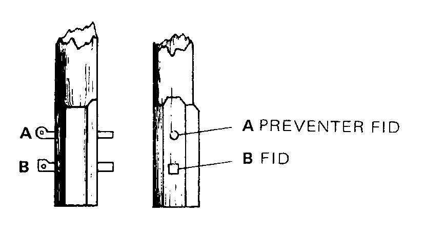
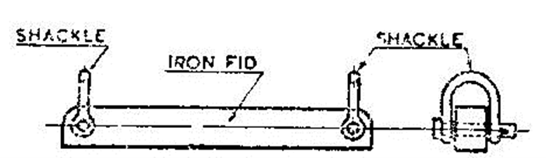
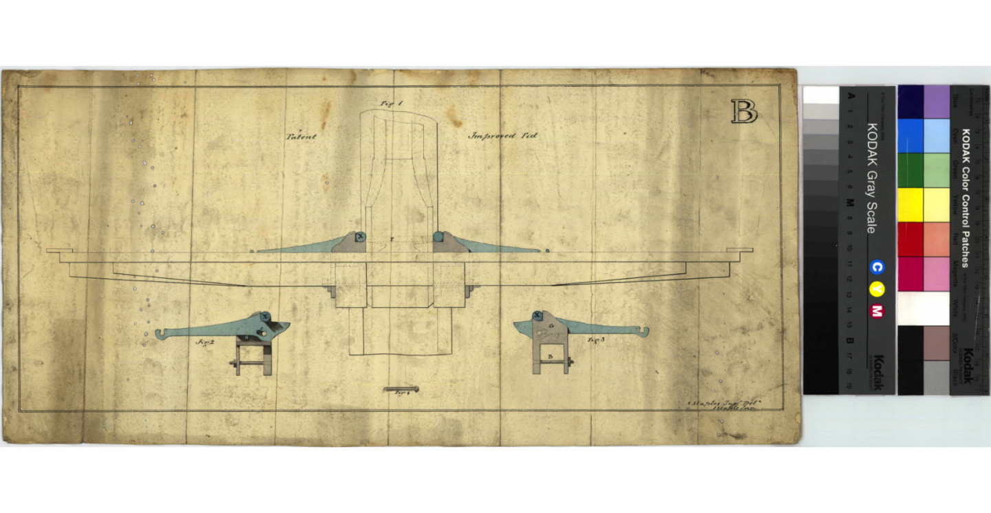
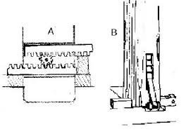
Grant, this an era in which a lot of things were happening. The type of fid may have been one of several designs and possibly influenced whether the tops were iron or wood. Also, by this time preventer fids were also in vogue, these were iron round rod put in about 8" or so above the fid - see attached set-up from Lees page 7. I have also attached another commonly used one in Clippers of this era from Underhill, Masting and Rigging the Clipper and ..., Plate 6. Another from the Rigsarkivet Plan C460b, and a line drawings for a patent jacking fid (cannot remember the source). The fid arrangement provided by Alan is another option for topmast fids. Sorry to confuse you further, but as you see there were a lot of options in this period. My suggestion is that if a reasonably simply rigged vessel, use a simplified fid arrangement unless you can find better or more specific info. cheers Pat