BANYAN
-
Posts
5,573 -
Joined
-
Last visited
Content Type
Profiles
Forums
Gallery
Events
Everything posted by BANYAN
-

HMCSS Victoria 1855 by BANYAN - 1:72
BANYAN replied to BANYAN's topic in - Build logs for subjects built 1851 - 1900
Thanks Eberhard, PE really helps with this. No way I could have cut those strips so consistently cheers Pat- 988 replies
-
- 3
-

-
- gun dispatch vessel
- victoria
- (and 2 more)
-
She looks great Dave; very nice job. As you said she looks particularly good with the backdrop painting, but as others have said keep the dust off her. cheers Pat
- 742 replies
-
- 4
-
-
- constitution
- frigate
- (and 1 more)
-
Take as long as you like between updates if this is the result ED; very nice rigging work (as usual). I learned the hard way about cutting the tails of the running rigging to early cheers Pat
- 3,596 replies
-
- 2
-
-
- young america
- clipper
- (and 1 more)
-
HMCSS Victoria 1855 by BANYAN - 1:72
BANYAN replied to BANYAN's topic in - Build logs for subjects built 1851 - 1900
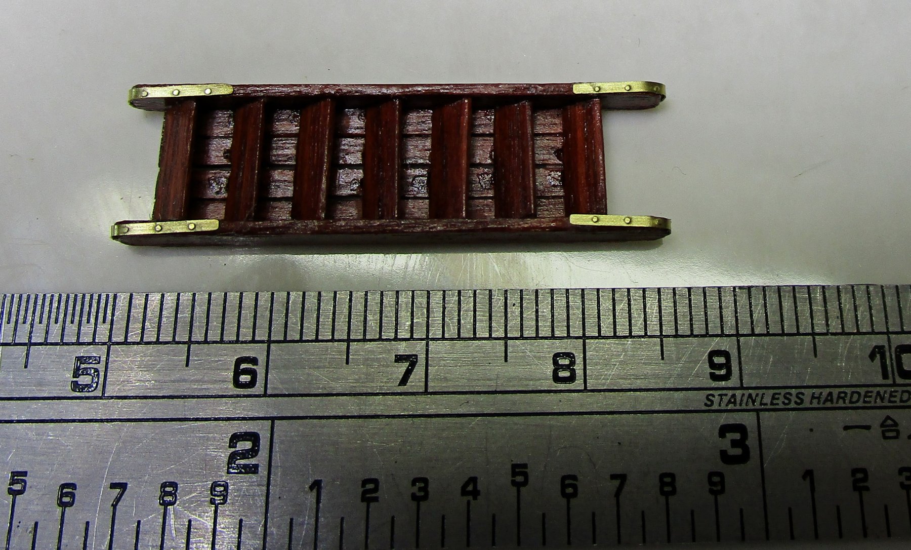
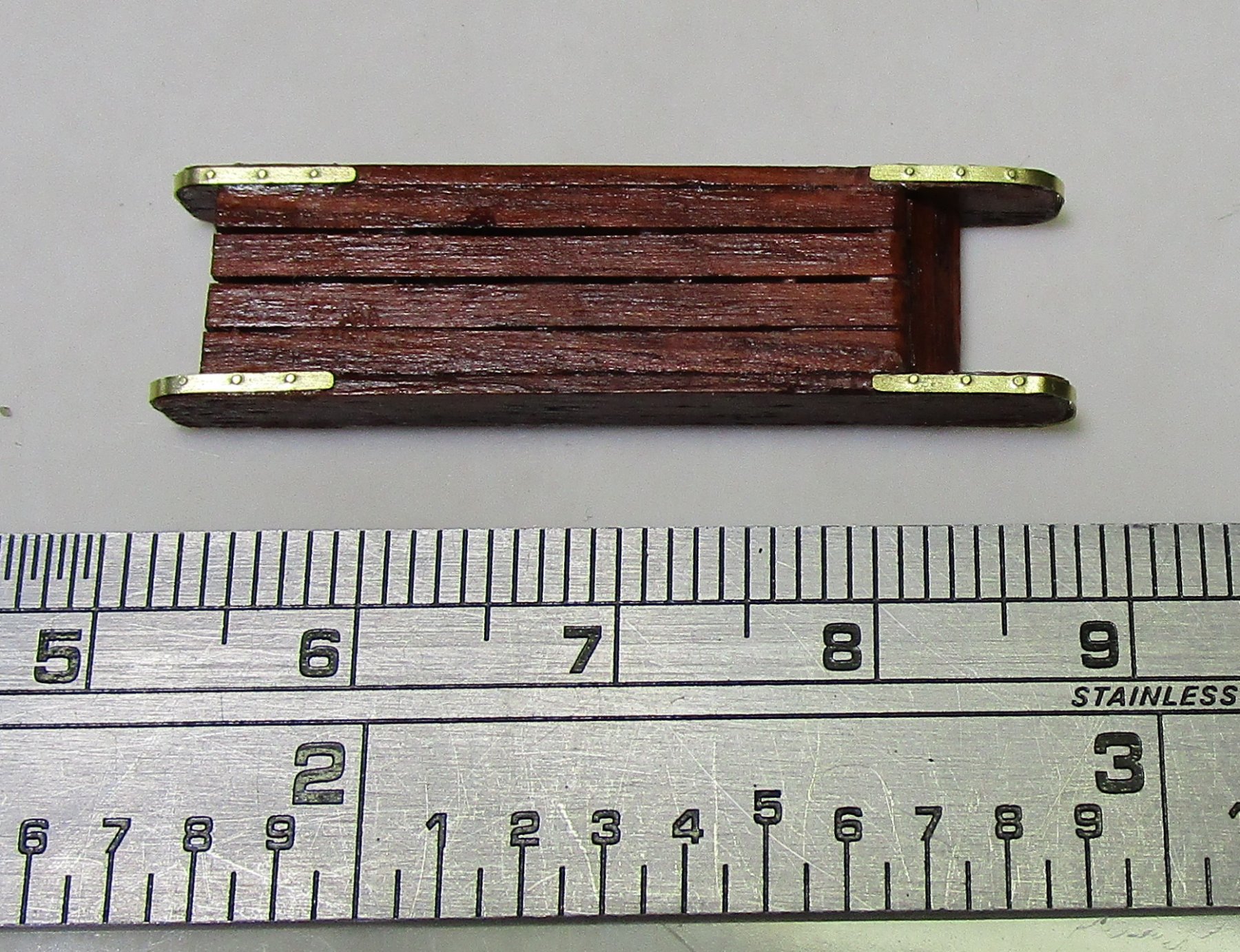
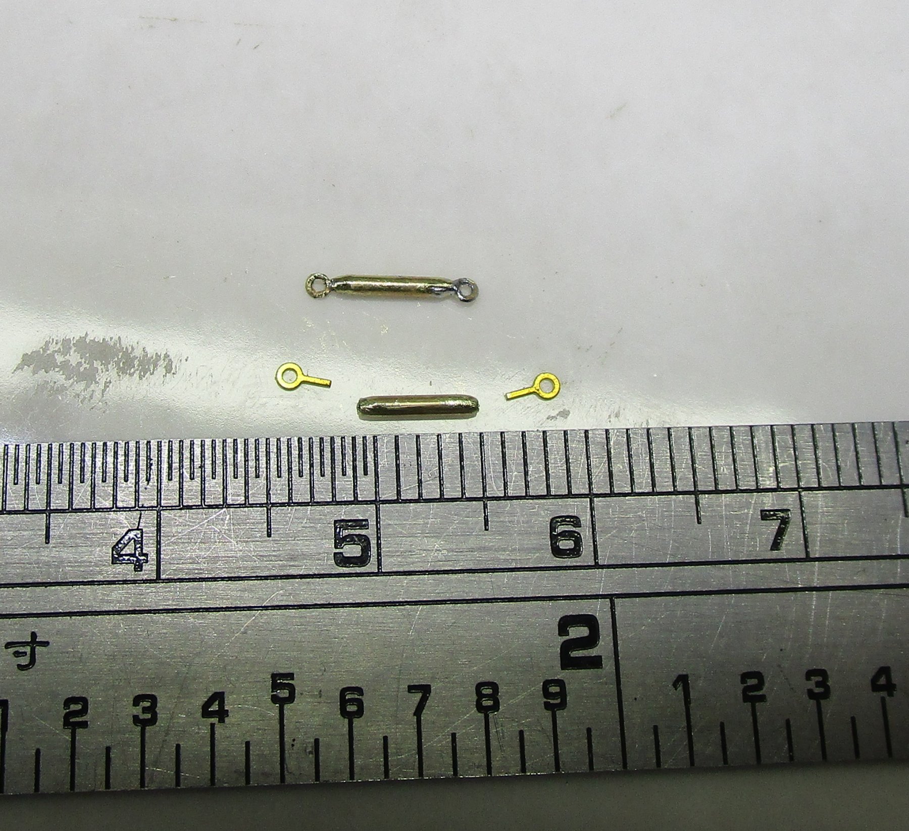
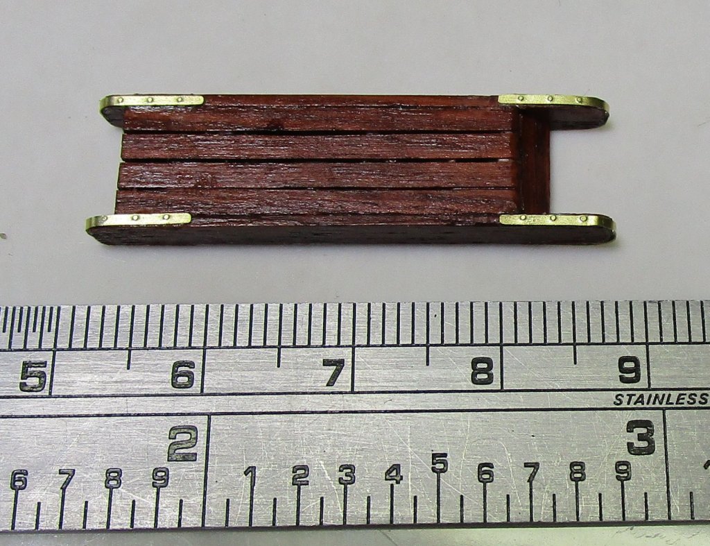
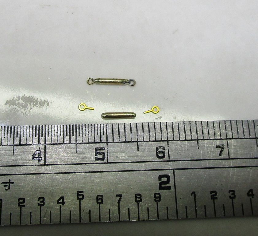
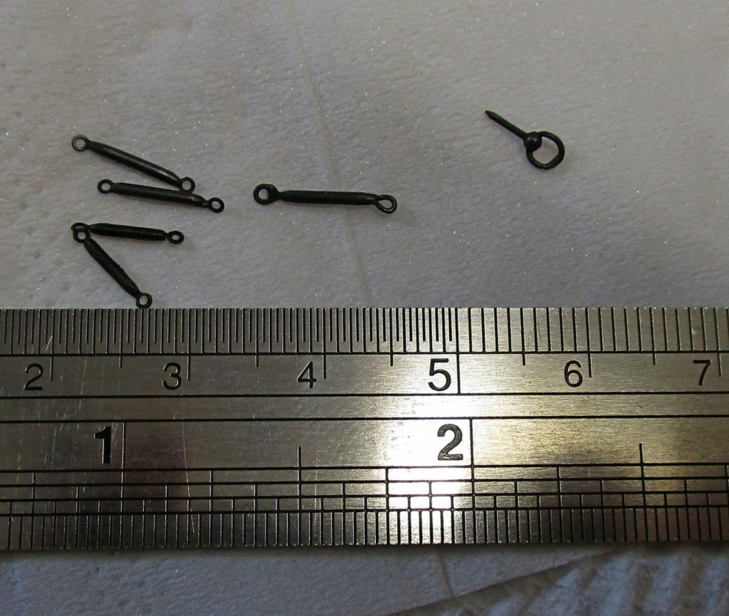
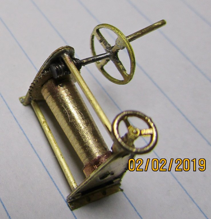
Some further small updates; not much but a start on the Accommodation Ladder (by another member) and I have started on some rigging screws for the funnel chains and the first of the broadside gun breeching rope ring bolts. The first two photos show the top and under sides of the main part of the accommodation ladder - wood unknow. The second two photos shows the parts for, and the made up and blackened rigging screws, and ring bolt etc. The slightly larger rigging screw will be used elsewhere. cheers Pat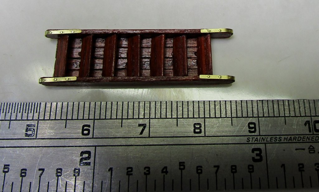
- 988 replies
-
- 15
-
-
- gun dispatch vessel
- victoria
- (and 2 more)
-
Now you have 'dropped' him in it Steven A 'tongue in cheek' reference to our 'extremely' dangerous Koalas Druxey - cause a lot of damage and injury when they 'drop' out of the trees Just a warning to all those tourists looking up Sorry John hijacking your thread here. cheers Pat
-
The world's weather is going nuts; floods and fires here, freezes and snow on the upper half - stay safe one and all. Sounds like you were well prepared at least Rob. cheers Pat
- 1,205 replies
-
- 3
-
-
- great republic
- clipper
- (and 1 more)
-
Looking good Steven, and you have thought this through thoroughly . I think the idea of removable handles is a good one as the crew would still need to have access around the forecastle for various tasks. cheers Pat
-
Nice 'get' - that looks like a Jim Byrnes draw plate (Model Machines)? cheers Pat
-
That looks good Greg; some of those hull 'scrapes and dents' look very realistic. cheers Pat
-
Hi all, I have a Lanco lathe that was given to me and for which I had plans to use in this hobby; however, I have decided the Sherline I have does all I need. I am selling this to get some money for more tooling for the Sherline. The Lathe comes in its original wood box, it is in good condition and spins freely. It uses 8mm collets (none included) which are readily available through the usual online shopping outlets on the internet. The photos show the lathe and the indexing stop; but I have not been able to determine what the bolts were for but were in the box. There are no other accessories but many are available through the above sources. These lathes are not cheap, but I will accept reasonable offers + shipping costs. Payment via PayPal or Direct Bank Deposit if interested please. Please PM me for details if seriously interested. cheers Pat
-
Mate, that's the way I work all the time - ALL at sea - Knowing your work I am sure it will be a thing of beauty when you finalise the transoms. cheers Pat
-
Looks good Steven; I hadn't realised how small this was until you placed the match against it. some very nice 'bashing' there. cheers Pat
-
HMCSS Victoria 1855 by BANYAN - 1:72
BANYAN replied to BANYAN's topic in - Build logs for subjects built 1851 - 1900
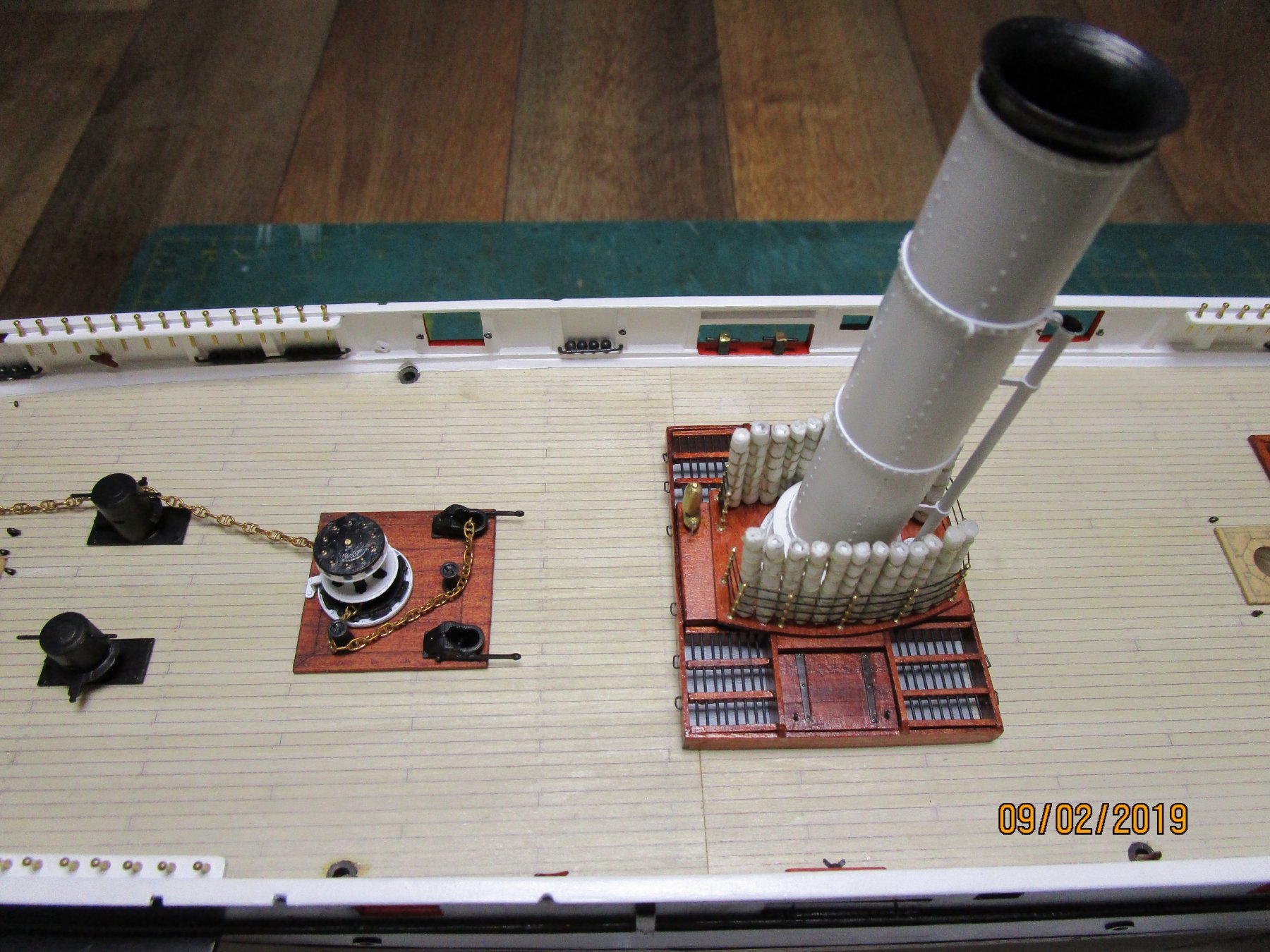
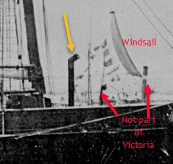
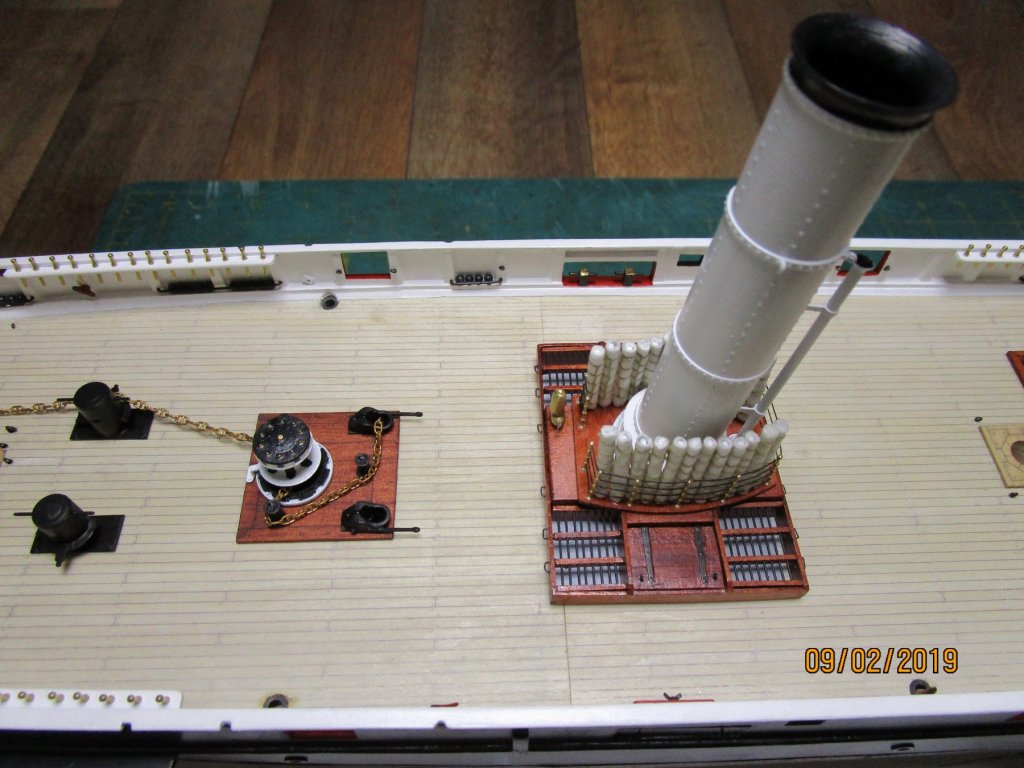
Hi Mark, this is the galley stove funnel (charlie noble) which usually (as far as I know based on plans of contemporary vessels) did not rise through a grating but was fixed direct to the stove riser somehow (usually just a sleeve arrangement passing through some form of deck seal/gland (simple wood gland probably). Sometimes this joint/ joining point was below deck. All the plans simply show a circle where it penetrated the deck What I am trying to determine is whether this joint was below or above during this era, and if possible, determine whether it would have been a two part, telescopic, or single funnel arrangement. I doubt it would have been more than 6 inches diameter and made from lightly cast iron? As such probably did not need chain/wire supports or the like - but you have raised another interesting question with that - it is rather tall and any wind force would have put some strain on it? cheers Pat- 988 replies
-
- 2
-
-
- gun dispatch vessel
- victoria
- (and 2 more)
-
Rob, I have a dremel version (also no longer made) but I find it just a bit too big - have never got around to modding it - but eventually :). Yours looked a little smaller but seeing Keith's link I think it is about the same size? I think the base of yours would also make it a little more articulated? cheers Pat
- 1,205 replies
-
- 3
-
-
- great republic
- clipper
- (and 1 more)
-
Very nice work Jason, I prefer the 0.3mm as well. Just noticed how nice the trunnion capping pieces are on the carriages. Did you make these? If not where did you get them? cheers Pat
-
Another way to make shackles
BANYAN replied to vaddoc's topic in Metal Work, Soldering and Metal Fittings
The horseshoe shackles are commonly referred to as 'bow' shackles and the straight or standard ones as 'D' shackles - each had a purpose. Bow shackles are often mistakenly referred to as anchor shackles (they look a little the same but a bow shackle has a more defined/larger arc or round than an anchor shackle with the latter usually a lot bigger as well. The curve or clearance of a bow shackle allows it to bear a load from more directions than the smaller curve in the straight sided 'D' shackle - so the bow can take significantly more side loads which is better for cargo handling etc. So a bow shackle is used where some amount of articulation may be needed. If only a straight (in-line) load/pull is required (as with much rigging) the standard or 'D' shackle is normally used. The smaller arc can take higher loads. The opening, with a bolt or clevis pin, is usually moused if a threaded bolt is used. I hope that helps clarify a little? cheers Pat -
Very nice woodwork Woodeater, those spars are very well executed. cheers Pat
-
HMCSS Victoria 1855 by BANYAN - 1:72
BANYAN replied to BANYAN's topic in - Build logs for subjects built 1851 - 1900
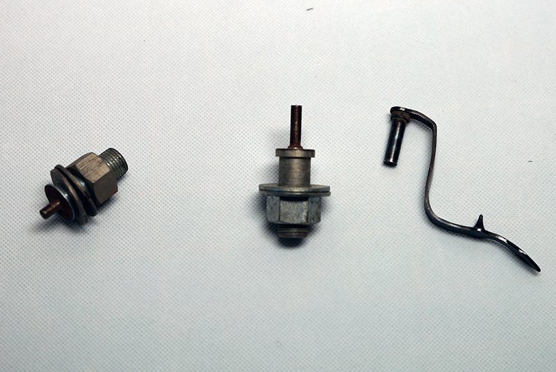
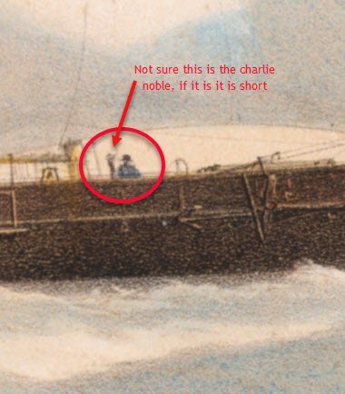
Another question for you more enlightened folks please. I am about to add the 'charlie noble' which is located between the fore hatch and foremast. It has a tall riser/funnel for use in harbour. I have not seen a photo with it fitted at sea, but one lithograph hints at a shorter one when at sea and an engraving a tall one again at sea - perhaps telescopic or a two part funnel? My main question though is how the funnel would have penetrated the deck. The stove is on the platform deck below, and even if the joint was below the upper deck, it would have required some form of waterproofed seal/gland at the upper deck. Not sure if you want the cook going up on deck to place the funnel in the correct position to draw air and clear smoke in the right direction - would that have been a function of the upper deck guys whenever they changed course? I don't see any wind vane adaptor on it to automate this. My leanings are to have a stub of the lower section from the stove penetrate the upper deck through some form of gland and then the charlie nobe (whether 2 piece or telescopic) would simply fit to this stub? I would then make that stub with a waterproofed cap that could slip on when the charlie noble was not fitted. I would greatly appreciate any feedback noting that we are talking 1855. I have found a letter from the Officer supervising the construction of the ship in London (Limehouse Docks) in which he states that the builders had chosen a galley/stove by Bedpath (The writing makes it look like Bedpath but perhaps Redpath? - There was a Redpath engineering in this era connected with improved stoves). Any info on the following most welcomed: 1. telescopic or two part? 2. type of upper deck gland/gasket or the like? 3. Bedpath/Redpath galley/stove (galley could feed 200 people and the stove was fitted with a "Grant's style condenser - This was a two part stove which could be isolated to cook from both or one part, and produce water with the other as required. cheers Pat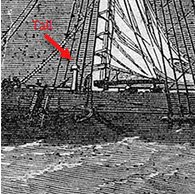
- 988 replies
-
- 3
-
-
- gun dispatch vessel
- victoria
- (and 2 more)
-
HMCSS Victoria 1855 by BANYAN - 1:72
BANYAN replied to BANYAN's topic in - Build logs for subjects built 1851 - 1900
Hello all, and many thanks for the likes and supportive comments. Carl, the levers are from brass strip (K&S) about 1.5mm wide, then hand shaped after drilling the holes at the appropriate distance apart. Eberhard, I cheated ; the Elliott pattern bitts are 3D printed then airbrushed - I added hex head bolt to the four corners as the hold downs. There should be a second set of bolts further in but I would damage the part adding those. The compressors are correct for the Brown and Harfield pattern of that time as far as we can research. They were the same as fitted to the 'Queen of the South' a contemporary mercantile vessel of 'Victoria' and commanded by Captain Norman, who was also the commissioning commanding officer for the 'Victoria'. One of the Brown and Harfield patent drawings actually shows the fit as on the 'Queen of the South'. There are two cable stoppers up forward near the hawse pipes, and these after pair, leading into the 'naval pipes' look a little different and were called 'controllers' but had the same function - control the run out speed of the cable as it approached the desired length on deck, and also to stop the cable slipping back. They took no real strain, that was done by the stoppers and the capstan. In Victoria, the cable lockers were located midships (5 tiers athwartship as far as we can tell) just forward of the stoke hole forward bulkhead so we believe they are positioned correctly. My understanding so far (as we don't have a better 'internal mechanism' drawing) is that the upper deck lever was actioned with a 'handy billy' which then acted on the horizontal lever below deck as per a standard compressor - no detail of the linkage found yet. If you have some additional info it would be greatly appreciated. cheers Pat- 988 replies
-
- 4
-
-
- gun dispatch vessel
- victoria
- (and 2 more)
-
Looking forward to seeing all that great detail come together at the business end Steven; looking good. cheers Pat
-
Great progress Rob; looks good. I like that vice you use too - ideas, ideas cheers Pat
- 1,205 replies
-
- 2
-
-
- great republic
- clipper
- (and 1 more)
-
HMCSS Victoria 1855 by BANYAN - 1:72
BANYAN replied to BANYAN's topic in - Build logs for subjects built 1851 - 1900
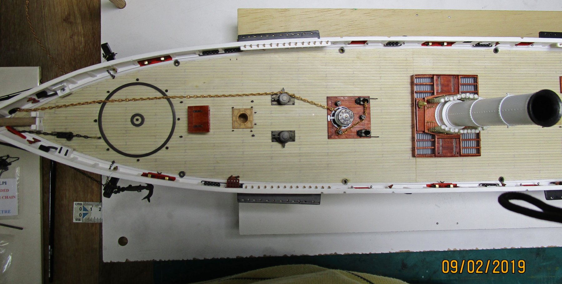
Hi again folks, another small update with some additional detail to show. I have now added the capstan, Elliott bitts and cable compressor after checking to be sure there was sufficient room for the bars to be fitted and turned. The men would have had to peel off and regain a vacant bar in places though as even with the space available it was pretty tight. The cable has yet to be blackened and fitted properly. At least the contrast shows how it was put onto the capstan. These are 3D parts we had printed but I had to replace the control levers as the parts are so small they broke too easily. I have not included a ruler but for an idea the levers were only 9mm long and less than 1 mm wide. I have also dry fitted the stoke hole skylight/ventilator with the funnel fitted and hammocks in situ. I will add the chain tie-downs before gluing it into place. The other shots provide some idea of the deck layout and fittings now added. I have also had a chance to adapt one of the winches to better show the worm drive - still a good clean required as you can see all the filing dust. cheers Pat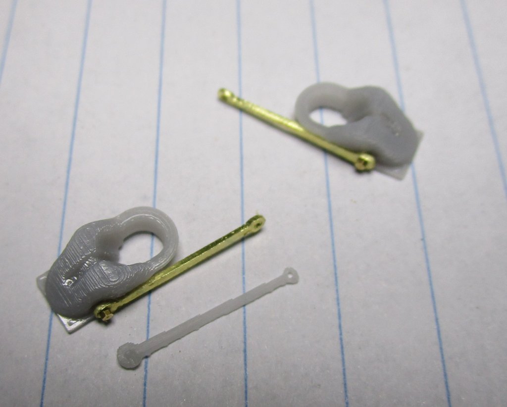
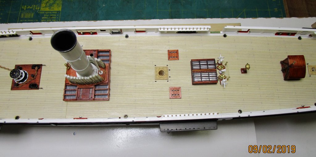
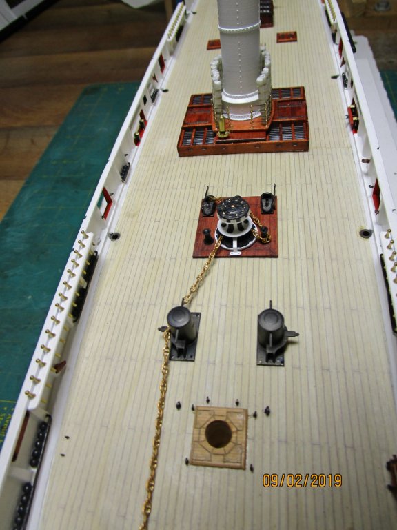
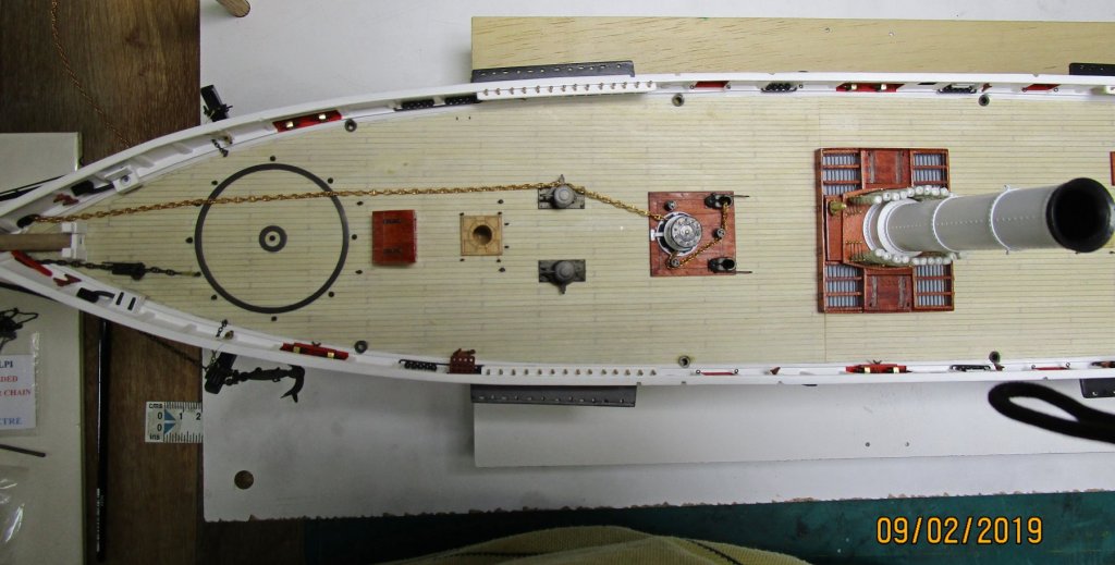
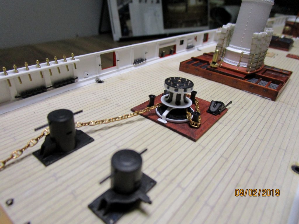
- 988 replies
-
- 17
-
-
- gun dispatch vessel
- victoria
- (and 2 more)
-
That is some very nice detail no matter what scale, but impressive at your working scale. And... you have a permanent memento of your work soaked into one of the parts - no arguing about who made the model as a simple DNA test will resolve that Surprising how much a small think like a bandaid in an awkward place can interfere. cheers Pat
-
Steamboats and other rivercraft - general discussion
BANYAN replied to Cathead's topic in Nautical/Naval History
I think Druxey nailed the first. Asto the second, if it is the same thing you are talking about, they may simply be large scuppers similar in design to a house downpipe? cheers Pat- 281 replies
-
- 2
-
-
- Steamboats
- riverboats
- (and 3 more)