


BANYAN
-
Posts
5,964 -
Joined
-
Last visited
Content Type
Profiles
Forums
Gallery
Events
Everything posted by BANYAN
-
 Hi Eric, I know the feeling, I too am guilty of such processes - moving ahead without being fully focussed. I wish you well in your travels and I am sure you will be able to fix the 'boo boos'. cheers Pat
- 599 replies
-
- 5
-

-
- sidewheeler
- arabia
- (and 4 more)
-
There are 'rivet counters' (my preferred term) no matter what you do Michael ; the other benefit of vertical slots is that any moisture will drain better. cheers Pat
-
Oh well, I tried More nice work; very effective faux-screws Michael - look the real thing! cheers Pat
-
Very nice joinery Michael; the wood is an excellent choice. Now I have about a dozen doors in the house if you wouldn't mind cheers Pat
-
Looooove those bollards - very nice executed Keith; the house guests must have inspired your work cheers Pat
-
Hi Steven, reading "iron-throwing ropes" - could not another possibility be grapnels for throwing during boarding? cheers Pat
-
Very nice panel work (joinery) Michael, and a very good explanation of how you achieved it. cheers Pat
-
The rudder look very good Alan, very nice work indeed. cheers Pat
-
"Satisfied" is just a tad of an understatement! They are excellent examples of miniature engineering and look so real. Have an extra rum ration for your efforts What did you use for the miniature bolt heads in the plinths? Probably not much holding power but they look good and very much in scale. cheers Pat
-
Hi Mikko, another welcome to the forum from 'Down Under'. Nice looking model, plently of helpful folks here to assist should you need any advice. cheers Pat.
-
A warm welcome from downunder; look forward to seeing your work. cheers Pat
-
Thanks Steven, I will have a look around as there are a few down this away I will probably be up your way in the not too distant future and will give you a bell before hand. cheers Pat
-
Very nice work michael, this will result in a authentic looking paneling. Will that card be prone to 'swelling' in the water environment? I am sure you have thought of that and will be interested to see how you seal it, particularly the edges. cheers Pat
-
Thanks for the updates Tim, this is a very fine model and it is interesting reading how you research and approach the making of the various components - duplicate just allow usd to enjoy the detail and workmanship twice to remove them simply edit your post, and in the strip at the bottom showing the thumbnails of all your uploaded image files, simply click on the delete icon at the bottom of the thumbnail. cheers Pat
-
The anchors look good Steven, that chain looks prety good too - would you mind advising the links per inch please? Also is the shop local or online? I am assuming local so a trip up your way may be in the offing. cheers Pat
-
Good solution, a significant improvement of the model compared with what you started with. cheers Pat
- 740 replies
-
- 1
-
-
- Tudor
- restoration
- (and 4 more)
-
HMCSS Victoria 1855 by BANYAN - 1:72
BANYAN replied to BANYAN's topic in - Build logs for subjects built 1851 - 1900
Thanks for the feedback Eberhard and John; appreciate your suggestions. I think you may be right re the positioning of the chock as the darker section (extension) could be something else. John, WRT to the cranes, a good point and I will revert (again ) to the gooseneck option I think; however, note that "Victoria" was minimum manned (along mercantile manning standards), but that said ash removal would not have been overly onerous on the crew most of the time. I say this as one of the design considerations made by the designer ,and insisted upon by the build supervisor, was a heavier (than for similar RN ships) spars to allow her to be undersail for the majority of time (to save on fuel as suitable Coals were scarce in Australia at the time). The engines were provided to allow her to operate in any condition when in her 'saving of life at sea' role, or, if required, in battle . I have been looking for a 'direct' connection between the Contractual wording of "iron crane" and gooseneck davit (or derrick), just to verify this but have found nothing yet; may just have to run with this as an assumption. I was running with derrick as it is more crane like? I too initially, and have reverted, was thinking a more simple arrangement would have sufficed. Also, the Contract was very specific in using the term davit for the boats and the fish davit??? Oh well, yet another conundrum. Thanks again Pat- 1,021 replies
-
- 4
-
-
- gun dispatch vessel
- victoria
- (and 2 more)
-
Edge Gluing Planks?
BANYAN replied to turangi's topic in Building, Framing, Planking and plating a ships hull and deck
Hi, I think it really depends on the finish you want to apply. If painting the hull, you can edge glue with PVA or CA but if a clear, stained and varnished finish any glue will more than likely result in a 'splotchy' finish no matter how careful you are as the glue penetrates the wood. More experienced modellers may be able to give better advice. cheers Pat -
Hi again, the distance seems OK to me but I will leave to more experienced and knowledgeable people to respond more adequately The bowsprit (outer end) for my Victoria (1855) is 23 feet (for a ship of 166 feet between perpendiculars and of 580 tons) so you are in the ball park I think ? I am unfamiliar with spritsail yards and the like so can't offer too much more to assist you; sorry. It is surprising what info is stored and what is lost. For example I have hundreds of letters written between the Crown Agency, the build Supervisor and the Governor of Victoria at the time, many of which refer to literally nearly a hundred drawings/sketches and plans - while the letters have been preserved, not a single plan or sketch has been cheers Pat
-
Hi Druxey, I read that as Main Mast above the deck 24? Asto the extension, this may relate to an extension of the head, but your ship may be a little early for that. Mid-19th C ships had extensions added to make them "Taunt" as described by Kipping and Fincham (that is tall). However, if we interpret the above deck measurement as being from the partners to the hounds (which is standard), the extension may be referring to the 'head' or doubling? cheers Pat
-
HMCSS Victoria 1855 by BANYAN - 1:72
BANYAN replied to BANYAN's topic in - Build logs for subjects built 1851 - 1900
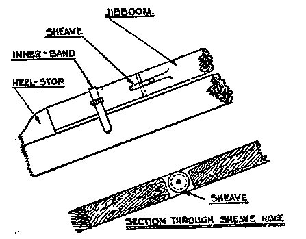
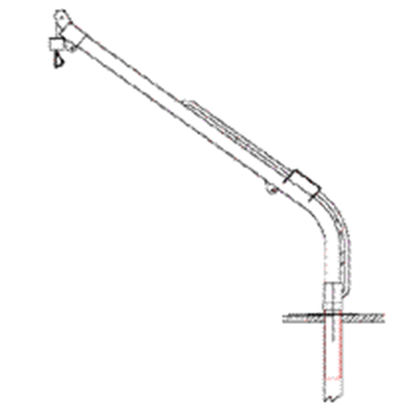
Hi again folks, yet another issue I am trying to resolve (well several actually) relating to the bowsprit and Jibboom (noting 1855 time frame) Q1. From Kipping I have sufficient information to dimension and shape the spars. What is not given, and not shown in any plan, is what ratio is used to determine the housing lengths (bed to step of the bowsprit, and the doubling of the jibboom onto the bowsprit. Is anyone aware of these ratios? As best I can determine the inner end of the bowsprit was only 5 feet - is this too short for a 23 foot bowsprit? Attached is a drawing I am doing which is superimposed on the profile photo of the ship. The profile and photo do not fully align as the photo is taken with the sip laying with a slight stbd bow inclination so the angles (and lengths change). Q2. You can see where I have circled or called out possible joints for the heel chock/jibboom. From what I can make out of this photo (not great quality as it was taken in 1867/8) is where I think the heel chock ends, but not sure where the butt joint is. Both options are viable according to Kipping and to Underhill, whereby some ships of this era still employed a small/short chock, whereas other ships, especially clippers, used a longer version. see other attached drawing from Underhill. I am leaning towards the latter (longer version) as there appears som rounding down (more than the proportioned shape of a jibbom) evident. that said though, this would leave a shorter housing? Hence Q1 (part 2) Q3. the last question relates to interpreting the bopwcap as shown in the image. My read is that as it is so close fitting it is more likely to be an iron cap rather the squarer and larger wooden (old style) cap? All comments ans suggestions most welcomed. cheers Pat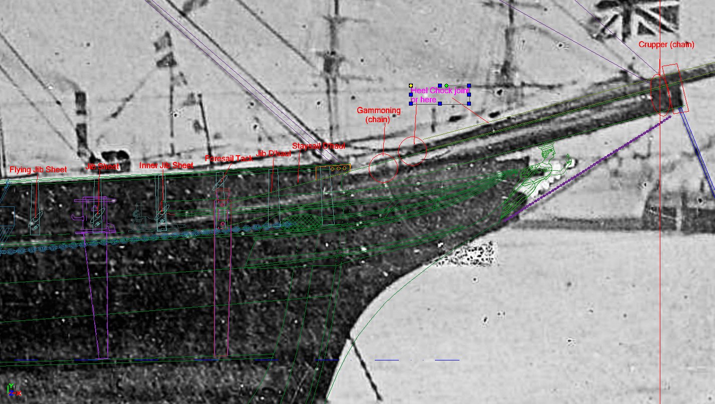
- 1,021 replies
-
- 5
-
-
- gun dispatch vessel
- victoria
- (and 2 more)
-
HMCSS Victoria 1855 by BANYAN - 1:72
BANYAN replied to BANYAN's topic in - Build logs for subjects built 1851 - 1900
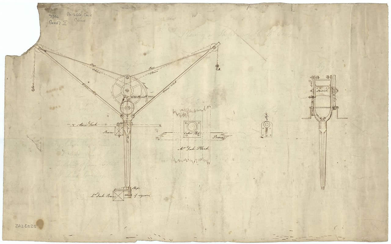
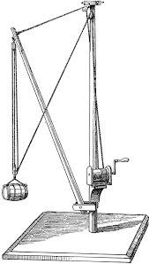
Thanks Eberhard, I've not found much either. I have assumed ash chutes as there is some reference to these in contemporary ship plans, and I have read that the ash, once raised was transferred by wheelbarrow to the lee chutes for disposal. The Contract called for portable 'iron cranes' which I read as 'shiftable' So three options; a gooseneck arrangement, a derrick arrangement or a full on crane. The NMM has sketches for two such cranes for this period, but they appear a little large and will have been obvious in the imagery. My assumption then is that when required the crane would be moved to the 'lee side' and would only need a reach to service the hatch and barrows. If a derrick was used, the reach may have been sufficient to allow the ash to be dumped overboard without transfer to a barrow. The derrick could be dismantled easily when not required and maybe why it cannot be seen in the imagery. I am leaning towards the simple derrick crane shown below. cheers Pat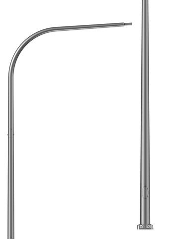
- 1,021 replies
-
- 5
-
-
- gun dispatch vessel
- victoria
- (and 2 more)
-
Nice production run Steven (cheaper by the dozen ) cheers Pat
- 740 replies
-
- 1
-
-
- Tudor
- restoration
- (and 4 more)