HOLIDAY DONATION DRIVE - SUPPORT MSW - DO YOUR PART TO KEEP THIS GREAT FORUM GOING! (Only 53 donations so far out of 49,000 members - C'mon guys!)
×


BANYAN
-
Posts
5,941 -
Joined
-
Last visited
Content Type
Profiles
Forums
Gallery
Events
Everything posted by BANYAN
-

Magnifying headset advice....
BANYAN replied to CPDDET's topic in Modeling tools and Workshop Equipment
Ditto Dave, I am currently using a brand with interchangeable acrylic lenses which I have grown to dislike for two reasons. First they mark and scratch easily, and secondly, if changing out the lenses, their designs make them prone to easy breakage (and if you accidently stress the folding mechanism. I would rather pay for a good set of glass lenses now I think and have started looking around. My criteria now are: 1. I would prefer glass lenses with at least 3 levels of magnification with focus (work) point at about 15 to 20 inches 2. hI would also prefer a head band mounted version (rather than spectacles add on, preferably with LED light mount option 3. Open sides so as not to restrict view angle range (loupes are too restrictive). Some brands that come are are the higher end Donegan 'optivisor' with glass inserts, Magni pros, and DKM. I will be very interested in better better quality versions if that is the way you prefer to go also. I seem to go through the cheaper ones all to fast (but may be a sign of my aging eyes ) cheers Pat -
Now that is a clever way of resolving that problem! You were fortunate to find eyelets to the exact diameter you needed, which sure saved on some manufacturing. cheers Pat
-
HMCSS Victoria 1855 by BANYAN - 1:72
BANYAN replied to BANYAN's topic in - Build logs for subjects built 1851 - 1900
Thanks Tony, you made my day with your comment re local history; exactly what I am trying to achieve here - preserve the history of this ship and, thanks also for the 'kudos'. cheers Pat- 1,008 replies
-
- 3
-

-
- gun dispatch vessel
- victoria
- (and 2 more)
-
That is some very nice clean work Keith, a pleasure following this build and learning some new ways to to do things. cheers Pat
-
HMCSS Victoria 1855 by BANYAN - 1:72
BANYAN replied to BANYAN's topic in - Build logs for subjects built 1851 - 1900
Thanks Ed, Rob and Keith, appreciate the feedback from such fine model builders. Six carriages now made, just waiting for some PE and the barrels. I have made a start on the gun tackles - ugh! Talk about a frustrating task with 2.5mm blocks and 2mm hooks - one down only 11 to go cheers Pat- 1,008 replies
-
- 6
-
-
- gun dispatch vessel
- victoria
- (and 2 more)
-
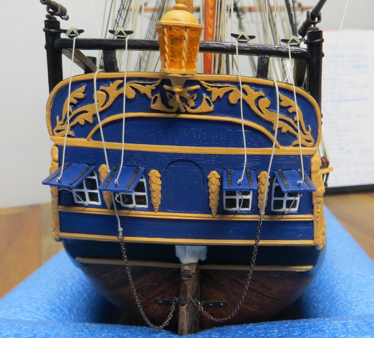
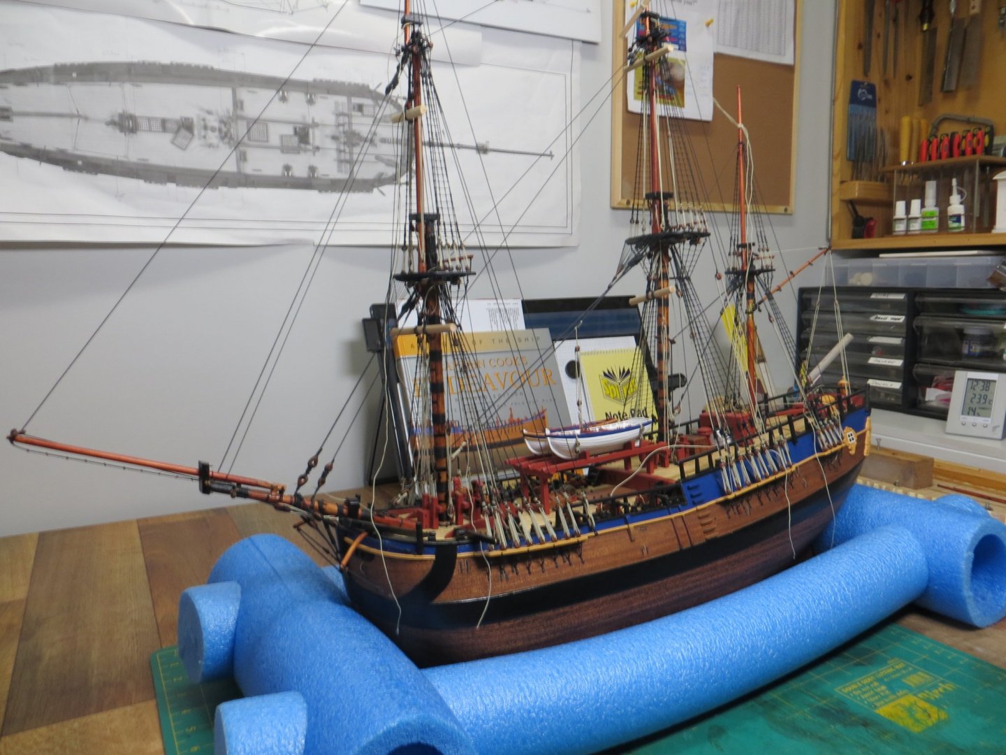
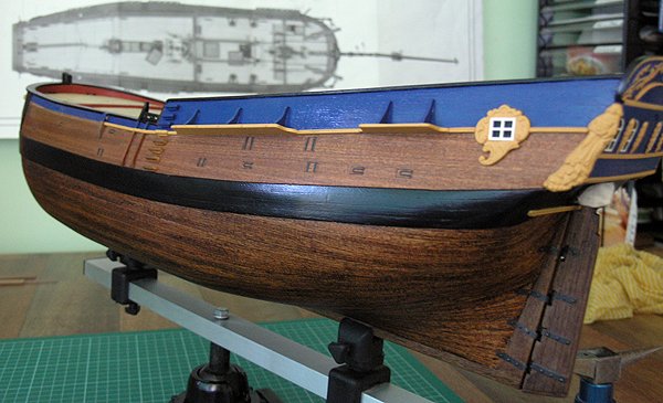
Hi Brett, for something left of field, I used a combo of a hull/clamping vice and pool 'spaghetti' The latter is cheap, works well and even allowed me to transport the model (even with the masts and rigging) with no problems at all. The slots allow the hull to be restrained, but simply lifting the hull you can lay it at any angle on the foam without damage to the planking etc. The sides and length can be adjusted as needed; and the round holes to accept the longer side pieces are precut, but it is easy to make new ones. I was lucky that the precut holes worked for me at 1:64. This is my Endeavour being rigged (top) some years ago, and being held by the keel clamp.
-
HMCSS Victoria 1855 by BANYAN - 1:72
BANYAN replied to BANYAN's topic in - Build logs for subjects built 1851 - 1900
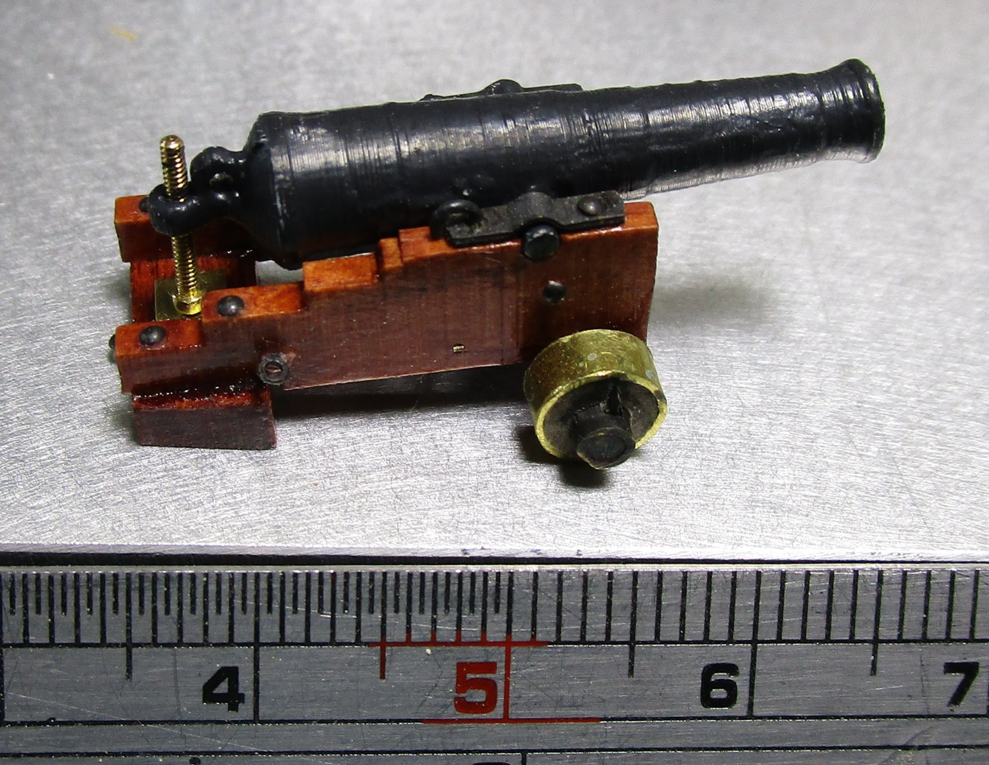
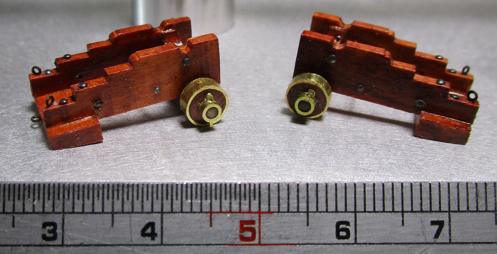
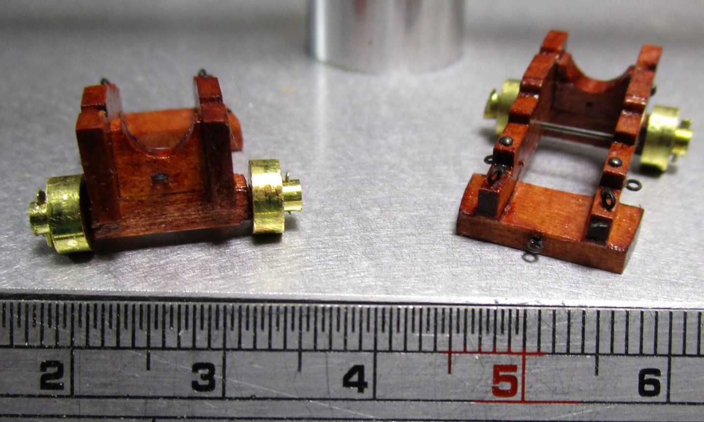
Hi folks, another quick update. I have been side tracked with research of late but have managed to make a start on the broadside guns. These were 32 pounder 25 cwt guns to the Dundas pattern, mounted on rear-chock carriages. As usual close ups show more dust, lumps etc than to the naked eye, so I am going to have to clean them up a little more yet As you can see these are small at 1:72, only 22 x 12mm at the widest, and the prototype is a rough 3D print barrel. The ones I will fit will be printed to a much higher fidelity and include the sights and gunlock - won't be as 'rough'. The prototype was used to ensure it fitted the ports etc correctly, and work out a way to run the production line. The rear worm drive elevating mechanism still has to have the handle added and the striker plate on the chooch will be a little more refined. The production version wheels are only dry fitted as I am still trying to determine whether to blacken the outer hub. the photo I am using as a reference (of the actual ship's gun) and contemporary information suggest these, and the wheel rims /rollers were made from gunmetal and not iron. They just seem a little too bright but my attempts to dull them have produced inconsistent results - I may just live with them cheers Pat

- 1,008 replies
-
- 15
-
-
- gun dispatch vessel
- victoria
- (and 2 more)
-
A lovely collection of bent sticks there John Looks like a great base for her planking. cheers Pat
-
Thanks Roger, until I came across this I too had the same interpretation re boats, especially the sea boat, from my service days alsdo. WRT Whaleboat / Barge, the confusing part here is that from all the correspondence she had polished timber interiors (a la Dignitary or other senior officer's boat), but there are so many other mentions of it being used for survey and other work. I do agree however, it was probably the designated 'Barge' as well as it being a workboat - boat's party will have been kept busy with the maintenance Now to establish the link with the Pinnace. I am lucky enough to have correspondence from the ship's (and boat) designer and the build superintendent where the designer specifically refers to it as the "Life Boat - Cutter" so I am happy with that terminology for the two lifeboats. The 1851 Steam Navigation Act was also very specific in stating that a steam ship of 'Victoria's' size, she had to carry two of them and they had to be 'buoyant. The NMM Collections have several contemporary plans for such a 'Life Boat - Cutter', and as the plans for the boats have not survived I have used one as a 'representative' version for use with the model. The dinghy was straight forward - so as mentioned above just the matter of verifying the relationship between Barge and Pinnace. I'll have to have a look in May's book also, never know what that may offer (should have thought on that book myself) . cheers Pat
-
Hi all, in researching my current build I am finding that different writers are using different names for the types of boats in the ship's logs, official correspondence and even the builder's correspondence). By the Specification, HMCSS Victoria was outfitted with 2 x Lifeboats, 1 x Gig, 1 x Whaler and one Dinghy. Except for the dinghy and gig, the other terms/names used are: Cutter, Cutter-Life Boat, Barge, Pinnace and even one instance of Launch. I have discounted the latter as it was a newspaper article and more than likely prone to misuse of terminology. I have been able to determine that the Cutter reference is to the Lifeboats as this was directly attributed by the designer (Oliver Lang) in one of his letters and Life Boat-Cutters were in common use in 1855 (I have found plans under that terminology in the NMM Collection). However, I am seeking confirmation that the terms Whaler, Barge and Pinnace all refer to the same boat (the whaler). A barge was usually used to convey the Commanding Officer and Dignitaries and the correspondence from the build supervisor advises that both the gig and whaler were outfitted more elegantly than the other boats (polished wood rather than painted inside). As these two boats were hung on the quarters where the 'Captain's' boats were usually stowed, it made some sense that the terms aligned (even if a tenuous link). I also noted while searching in the NMM Collections that the terms Barge and Pinnace were used together on the same plan in two instances so I have assumed these terms can be used alternatively also? Could someone please confirm or enlighten me as to whether I am on the right 'course' or not please? cheers Pat
-
Hi Greg, Yves has offered a really nice option cheers Pat
- 345 replies
-
- 5
-
-
- graf zeppelin
- trumpeter
- (and 2 more)
-
Beautiful work Eberhard; miniature perfection You don't happen to have a spare around do you? Just the other night I cam across a reference somewhere which I will need to find for you again; unfortunately just as I found it our woeful National Broadband Network (NBN) which is MANDATORY her can you believe, played its usual trick of losing connection). Hopefully I can find it again and I will copy, not that is much except a description which describes a similar horizontal tabl;e (as they called it) for communicating with the engine room - 1940s I think and it was under a patent listing I think. cheers Pat p.s. This is another one I had found c1858, similar bit a little more refined. Not sure where I found this as it was in the days I hadn't realised how important to note the source withing the image title - possibly from one of the contemporary 'The Repertory of Patent Inventions ' periodicals? I will need to try and track down the other one referenced above, but not so confident in finding it as it was one of those random things that popped up while doing another search.

-
Beautiful result, and thanks for the step-by-step for us mere mortals to follow cheers Pat
-
The bulkheads look good Mark, practice makes perfect huh? I could not make it out for sure but have you cut the rabbet yet? cheers Pat
-
Nice job and clever idea Pat cheers Pat
-
I can empathise Keith, our second grandchild arrived just three weeks ago Enjoy the moment and congrats to all cheers Pat
-
aghhhh no I wasn't - SORRY - I feel a twit.... Works well. many thanks cheers Pat
-
Thanks, still no go this morning but I am sure it will appear cheers Pat
-
Nice work Steven - unfortunately no matter how good the brush my hand shakes too much these days to do such fine artistry cheers Pat
-
Thanks Richard, I did, and I tried a direct access from your earlier link and no go - no biggie, just may take a while to filter through? cheers Pat
-
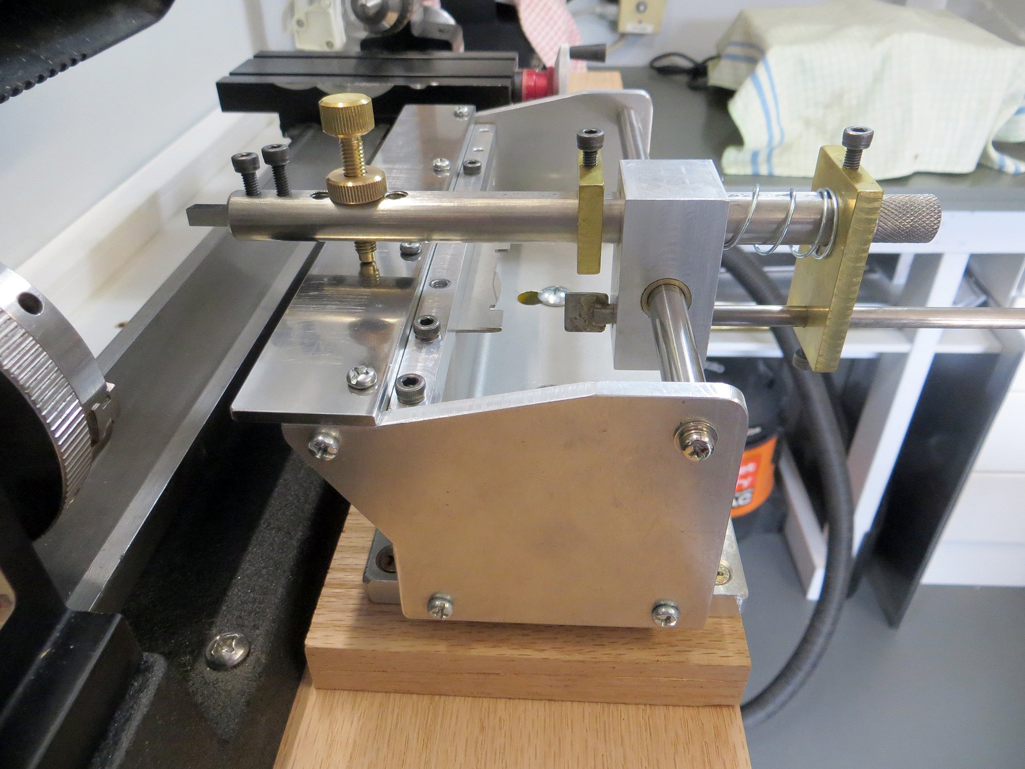
Duplicates for Sherline Lathe
BANYAN replied to John Rose's topic in Modeling tools and Workshop Equipment
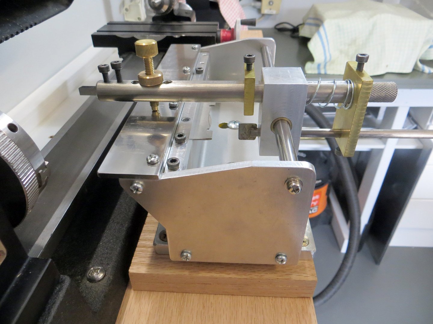
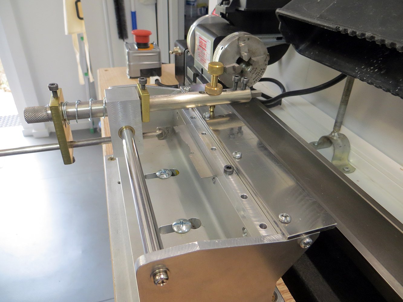
I also made my own using Druxey's published idea and pictures. I experience the same finish results and restrictions pointed out by Wefalck and Druxey, The greatest problem is getting the blade for the tracer to be fine enough to allow a precise copy. I am in the process of modifying my tracer rod to accept interchangeable blades which will be ground with a left flat, right flat etc. This will not eliminate the 'rounding' issue needed on the tracer blade but will make it a little more precise. Not great for smaller jobs but work fine for larger copies such as columns/pedestals etc. Note this design removes the need to free the cross slide as the cutting tool is ground to match the blade and is part of the duplicator. The template is held within the duplicator also as shown. I have also redesigned the way it is fitted to the bench since I took these photos. It now sits on a much longer aluminium base plate drilled with equally spaced holes (matched to the current mounting slot space) allowing me to better place it relative to the work. I have invested in some travellers and jackstand to support longer work also. The longer baseplate has also allowed me to utilise it to support an off lathe 'stop'. I am still adapting that to hold a micrometer head to allow repeated cuts to the stop. PLEASE ignore my learning 'whoopsie evident on the Y table - hence my need for a stop - major embarrassment) cheers Pat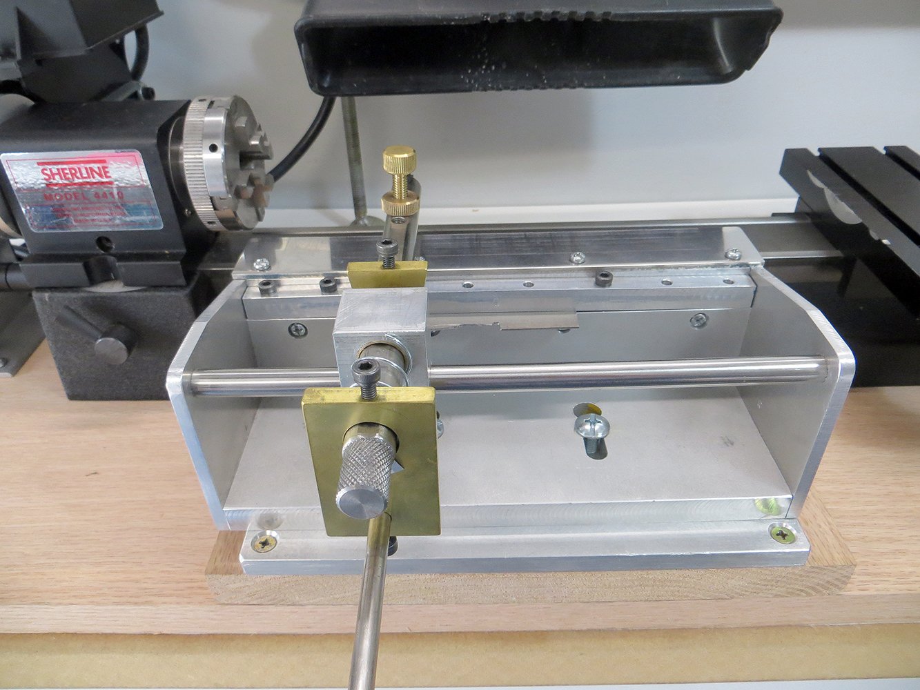
-
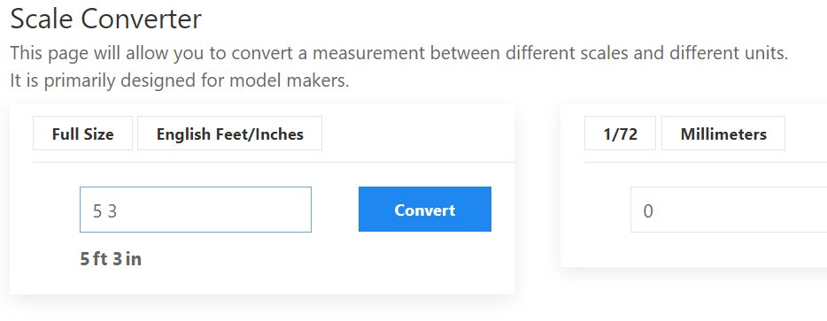
Many thanks Richard, appreciate that as it is a very handy tool. Have you uploaded the new version yet. I tired through my bookmark this morning and no change? The reason for my asking for the decimal is that many calculators etc now out put inches as decimal as it was 'too hard' for them to do the fractional readout. As a result I have several sets of dimension that are all printed as decimal inches I'll see if I can find some data on the other national metrics and forward to you if I do. It was just a suggestion which I am not sure how many will use. I know I have been bitten once or twice thinking I was using a standard foot but it was something entirely different. Perhaps a straw poll here using the polling option may help identify identify which dimensions would be more useful? to modellers? Many thanks again. Pat
-
Must have used 'Jeffrey's compound (marine glue) or the like? Either that or a very talented carpenter plugging the 'nails' with very tight plugs with grain oriented in the same direction. Either way the deck looks very 'clean'. cheers Pat
-
The skills will come back to you as you progress Joss; bit like riding a bike after putting it in the garage for many years The tops look great, must have been a tedious process doing all that drilling? cheers Pat
- 38 replies
-
- 2
-
-
- bounty
- caldercraft
- (and 1 more)
-
Thanks Richard. I will go back and recheck again, but it does not seem to work for me - the values under the input box does not update when entering the decimal as shown in the screen grabs (even if I click on the Convert buttons). I am using Chrome browser on a PC running Win10 pro 64 bit. Not intended as a complaint, simply raising a potential bug (probably my end) and appreciate your continued support. Thanks again. Pat