BANYAN
-
Posts
5,924 -
Joined
-
Last visited
Content Type
Profiles
Forums
Gallery
Events
Everything posted by BANYAN
-

Cleaning Small parts prior to blackening
BANYAN replied to src's topic in Metal Work, Soldering and Metal Fittings
They're the ones SRC - nice looking set those ones. cheers Pat -
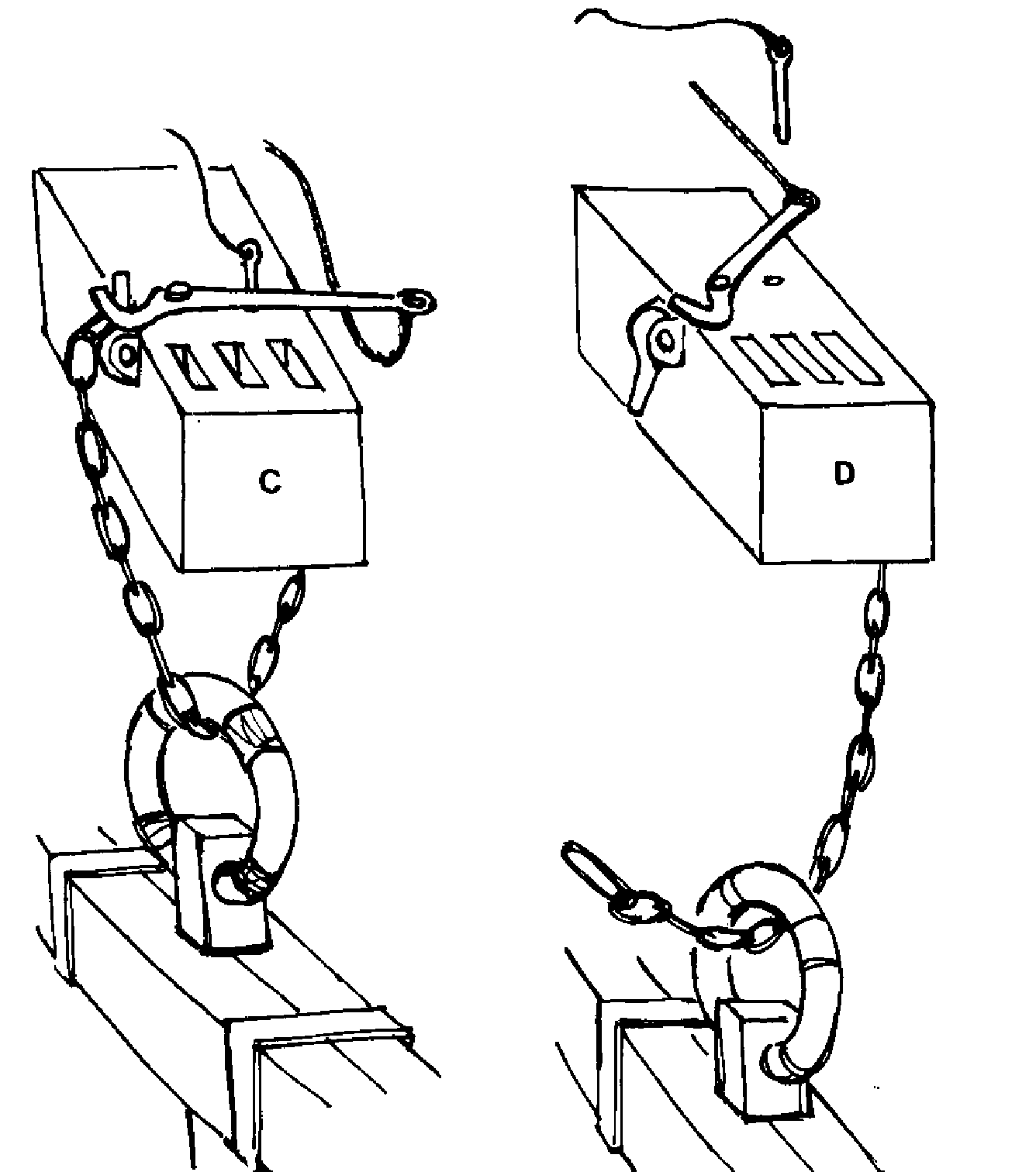
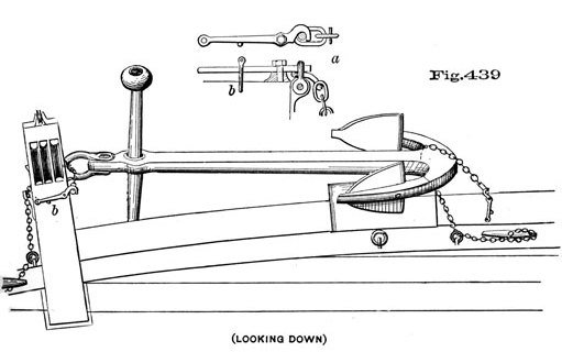
Hi Gregory, those 'trick stoppers' as they are known; this one being a 'Spencer' design, were a 19th century release mechanism. Other similar designs used a pressure plate instead of a swiveling lever, and others used different types of 'tumbler' mechanisms amongst other options to release the anchor. This is the mechanism I went with for my build of HMCSS Victoria (1855) I have included better pictures of the Spencer Trick Stopper, so you can see how it worked. Sorry to hijack the thread Vossie - but I thought this may useful to others at some time? cheers Ppat

-
Cleaning Small parts prior to blackening
BANYAN replied to src's topic in Metal Work, Soldering and Metal Fittings
Hi Sam, to answer your earlier question - depends - sorry. If it is one of those products with the protective/finish coat on them I still use the fibre-glass scratch pen; but, the ultrasonic cleaner has certainly reduced the number of times I have to use the pen. cheers Pat -
Very (VERY) nice model Rob; even incomplete. cheers Pat
- 1,208 replies
-
- 2
-

-
- great republic
- clipper
- (and 1 more)
-
Nice job on the fairing john, all looks nice and symmetrical. You may need that 'cone of silence' on Monday cheers Pat
-
Stunning model Ed; the rigging brings her to life. In 'Victoria' some lines/tackles were also led to eyes (Lang's eyeplates) in the channels - still trying to sort through that one though cheers Pat
- 3,618 replies
-
- 2
-
-
- young america
- clipper
- (and 1 more)
-
Hi Gregory, Vossie is working with a windlass close to the bows and riding bitts (see earlier picture). Capstan bars cheers Pat
-
Cleaning Small parts prior to blackening
BANYAN replied to src's topic in Metal Work, Soldering and Metal Fittings
I have tried several processes successfully but I have now settled on a more efficient way having purchased a small ultrasonic cleaner. I use Birchwood Casey (diluted) as the blackening agent. Always rinse and buff with a soft cloth or towel paper on completion and redip in blackener if required. As Mark points out rubber gloves when handling , then cotton gloves after blackening (until buffed and you are happy with the finish, as handling is usually not a problem for me after the item has been blackened and buffed. I use cotton once blackened until buffed as i found the rubber tends to grip the item too much making it harder to manipulate. Method 1: wash and rinse, soak in vinegar and rinse, soak in a weak acid solution and rinse then blacken and rinse again. I use a tea strainer (dipping type that closes which allows me to swish all the items around in the solutions. The acid can be diluted nitric, or muriatic (brickies acid) or even acetone. I only soak in each solution for about 15 mins and vigorously agitate quite often; but a longer soak if you have the time can create a better finish first up.. Method 2: (a little more time intensive) first I use a fibre bristle-pen to 'scratch' clean the entire surface of each item. I find this necessary on some after-market parts (especially K&S brass shapes) as they seem to be treated with some sort of finish - then as for method 1. This takes more time but usually yields an acceptable finish on the first attempt. be careful with the fibres from the pen (fibreglass) as the very small 'dust/pieces' are a real pain to get out of your fingers if they stick in Method 3: (if you have an ultrasonic cleaner - small ones are pretty cheap these days). Almost the same as for method 1 or 2 (depending on the type of brass i am blackening) but instead of a prewash in warm water and detergent I use the ultrasonic cleaner - a lot faster and better clean. With some trials I was able to blacken with very acceptable finishes without the vinegar and/or acid soak afterwards. I have settled on using the fibre-pen and ultrasonic wash before blackening on all my pieces now unless it is a very (very) small part made from soft brass - the extra time in using the fibre-pen results in a lot less rework. I hope this provides some help in choosing a method suited to your needs; cheers Pat -
I believe Keith may be on the right track. Even if two anchors are used it is possible the anchors would have been secured by the windlass alone. One likely scenario MAY have been that the first anchor is dropped, set then the cable secured to a riding bitt (having been stoppered, with the tail remaining wrapped around the windlass drum and back into the cable locker tiers. The second anchor could be dropped by a boat, set then secured the same way having the tails veer around the drum when that cable is not being worked, or 'leant back on' to allow the selected cable to be worked (after removing the turns from the riding bitts. I have heard of the windlass acting as the riding bitts also, in that case I would suggest the same procedure except there would be no turns transferred to separate riding bitts? Pure conjecture on my part - over to other for comment. cheers Pat
-
Beautifully crafted Keith; if I didn't know better I would have thought it the real thing. cheers Pat
-
Nice work Pat
-
Welcome back and glad to hear all had a good time on your trip. The pendants look good Dave; who's to say which is correct? I used the Sidney Parkinson drawings (port quarter aspect drawing) as my main reference for this. cheers Pat
-
It is a pleasure to see your work Chuck; the clean lines and crisp joints are always inspirational! cheers Pat
- 1,784 replies
-
- 3
-
-
- winchelsea
- Syren Ship Model Company
- (and 1 more)
-
Further to the advice CapnMac offers re deck numbering which is correct for USN vessels; the RN (and most Commonwealth Navies) use a different system of single digit designators (1-n) decks down from the weather deck (weather deck being 1 deck), and double digit (01 - nn) above the weather deck for upper decks - 01 deck being the next up from the weather deck. In this instance, as it is pre 1947, the 04 designation would align Offered only to clarify for other classes /nationalities of vessels. cheers Pat
-
Hi all, from my limited research so far I believe that in the RN (Service ships) it was preferential to 'box' the compass until later in the 19th century (once the quadrantal correctors had been proven proven) - this meant applying a known 'error' for each of the compass points (as well as allowing for magnetic deviation for the heading) when steering. Note: this term is more commonly known to mean "To know, and be able to recite the 32 points and quarter points of the magnetic compass from North, both clockwise and anticlockwise." BUT it is also the term applied to determining the magnetic compass' error for each of the 32 points and requires swinging the ship through 360 degrees around her anchor or a buoy - a practise still used in the 'Service' today for magnetic compasses. In the mid 19th century, mercantile ships 'commonly' used iron pieces implanted into the decks and deck furniture in an attempt to correct the compass on each compass point. Another earlier correction (I think from 1850s - but stand to be corrected) was the use of the "Flinders bar" a metal rod fitted within the pelorus/binnacle as a vertical rod? For the 'Victoria' (1855) I am reasonably confident that she was fitted with at least one, possibly 2, Gray’s prismatic azimuth type compasses with internal compensating bars. Sorry to hijack your thread Keith. cheers pay
-
Nice job on the 'bodging' Pat; a great improvement. cheers Pat
-
rail function
BANYAN replied to MESSIS's topic in Discussion for a Ship's Deck Furniture, Guns, boats and other Fittings
Another possibility, but less likely, is hat it may simply be a 'bent' rising timber to allow for the lead of some rigging such as braces etc? cheers Pat -
I do like to paint my models BUT, that is one stunning hull finish Keith. cheers Pat
-
HMCSS Victoria 1855 by BANYAN - 1:72
BANYAN replied to BANYAN's topic in - Build logs for subjects built 1851 - 1900
Thanks Gary, very much appreciated your kind remarks. cheers Pat- 993 replies
-
- 3
-
-
- gun dispatch vessel
- victoria
- (and 2 more)
-
Very nice job on the parrels UV; looks good fitted. cheers Pat
- 786 replies
-
- 2
-
-
- Royal Louis
- Finished
- (and 1 more)
-
Hi Pat, I fitted them as I based most of my build on the AOTS book (Marquardt). Note however, there are a few things in the AOTS that remain open to further research/questioned by other researchers, and a couple of errors. That said, I was happy to fit them as the colliers (of which Endeavour was first built) generally show them fitted, and being very 'hardy' vessels, this sort of reinforcing was probably essential - some further research may throw-up other info though. cheers Pat
-
Hi Rob, many thanks for looking in and your suggestions; I very much appreciate your contributions. I have a copy of the book and I am kicking myself (very hard ) that I have not checked it previously; it is one of those books I did not readily identify (changed opinion now) with this level of research as the author mostly provides drawings/illustrations with very little supporting text (need to trust he is accurate). That said, there are lots of examples of equipment, and in particular ship rigs, provided, and after looking at them I am confident in staying with my assessment/proposal of a 'Steamer Rig' as most (NOT all) steamers appear to use this, or a slightly modified version of the rig. Contemporary authors probably avoided defining it as a 'particular type' of rig, especially calling it a 'Steamer rig' (or something similar) as it was developed in the transitional phase of sail-to-steam powered vessels and there were some modifications / other rigs used in steam-powered ships - they would therefore have believed it to be a transitory evolution of a rig (as Druxey pointed out). Also, by the time the rig was established steam-power, along with iron construction, was well and truly preeminent and the 'need' to name these rigs was probably thought less relevant. However, I still believe (my opinion) that the very wide use of this style/type of rig in steam powered vessels, and its continued use well after steam became the main motive power for ships, that it can be 'identified' as a specific style/type of rig. The name I have offered should really be attributed to Kipping, and to a lesser degree Fincham, whom discuss the rig under the topic of 'steamers' without actually naming it so. Unfortunately, we cannot associate it as a Jackass Bark due to the fact Victoria (and other steamers) also carried a course on the main as well as the fore mast. However, his diagram of early steamers on page 92 (option B ) is a close fit once you add the clipper bow and associated rigging - that agrees with Kipping's description also. (Note the two part masts with long extension poles - combined Topmast and TG mast). A pity he does not provide some further text to support the drawings, as a 'scan through' of the rig illustrations tends to support the association of a two-part mast with fore-and-aft sail rigged ships. cheers Pat
-
Hi all, another update. After some deeper reading of Kipping and Fincham (both authors published in 1854) I think I have some resolution on this rig. Neither author (actually no author then or since) have actually named this rig. However, all authors tend to discuss the rig under reference to 'a Steamer' - that is, the relevant discussion relates to a subject (such as masts, or tops, or fittings etc) under the auspices of as fitted to a steamer. Based on their writing, supplemented with information gleaned from several authors and sources, I have established a 'common fit' for a rig that was used exclusively for steam powered vessels (paddle or screw driven). The 'rig' appears to have been derived when steam was used as auxiliary power (late 1840s/early 1850s) and sail was still the primary 'driving' force until much later when steam prevailed as the primary motive power. The rig appears to have been used well into the late 19th century. It also closely aligns with Victoria's rig with a few minor differences. These differences can be attributed to her merchant vessel design features and the 'whims' of the designer/builder. The research has also exposed that the rig, especially the forms of the Tops' framing, differed slightly between the 'typical' Service (Naval) and Merchant vessel fits. The rig also, as suspected, was a composite Barque/Schooner rig but can now I think be identified as a specific type which for want of a better term I will call "Steamer Rig" Essentially, the main characteristics of the 'Steamer Rig' are: 3 masts and a bowsprit. Two part masts with a taller (than for other similar sized vessels) single tree Lower masts and all with a single loose extension pole mast. The Fore and Main mast pole extensions were usually formed as a combined Topmast and Topgallant mast with short stub pole (to fly pennants, flags etc) - however, in one of those identified differences in Victoria, she also had the Royal mast included in this single Upper pole mast. The Mizen mast comprised the usual (for square rigged vessels) pole mast extension with no crowjack. The bowsprit is short, nearly horizontal, with a jib and flying jibboom in one. (The 'steeve' of Victoria's bowsprit was measured at 15 degrees up from the waterline as the reference (75 degrees from the vertical).) Square sails to the Fore and Main mast, Spanker/Driver on the Mizzen; Staysail, Jib, Outer Jib and Flying Jib to the Bowsprit/Jibboom. The Fore and Main masts carried a Gaff Trysail with Gaff booms ( or Boom-Sails as Kipping refers to them) - as large as the spacing between masts and deck equipment etc would allow for them to be conveniently worked. Some versions also occasionally carried Gaff Topsails (not in Victoria) Additional detail to assist identifying this rig includes: All masts were fitted with a lightweight skeletal form of Top at the Lower mast hounds only; no other tops/trees were fitted to the pole extension masts. The pole masts had stops/shoulders at the appropriate height where the yards for the associated yards were to be lifted; these were fitted with a iron and copper 'funnel'. Spreaders were not fitted to the Tops. Service vessels had different forms (framing) of Tops fitted to the Fore and Main/Mizen masts - curved rim on the Foremast only. Merchant vessels had the same, lighter (than Service vessel Tops) framed form of skeletal Tops fitted on all three masts; all had the curved rim forward. The lower yards were usually fitted with an iron-Truss, with an option of Truss or Parrels used for the upper yards Fincham also stated: The masting of steam-vessels is not subject to the same strict rules that are made to determine the masting of other classes of ships. The length of the masts and yards must, however, bear some general relation to the length and breadth of the vessel; but both this relation, and the positions of the masts, are subject to many variations depending on particular circumstances, especially on the service in which the vessel is to be employed, whether for long and short voyages, or only in rivers. The positions of the masts must, in many cases, be determined by the situation of the machinery, and the quantity of sail be regulated by the requirements incident to its employment. It is, however, important, on account of the obstruction which the masts and yards present in steaming head to wind, that they should be made as compact as possible. ………….. There is a significant amount of information on the shaping, form and fittings of masts for a Steamer provided by both authors, but their 'rules-of-thumb', or formulae, for reducing/tapering spars differ. Unfortunately neither (any) author provides a 'rule' for dimensioning the single pole extension. I will continue to find something on this and advise when i have anything worth mentioning. I hope this information helps others whom may need to use similar rigs to ships they are/or wish to model. cheers Pat