


ERS Rich
-
Posts
609 -
Joined
-
Last visited
Content Type
Profiles
Forums
Gallery
Events
Posts posted by ERS Rich
-
-
Hi Avi,
Wow, my heart sank when reading the beginning of your post. So sure glad that it worked out. Yes, there is a subtle, but after noticing, an obvious difference between the catalog picture and what was delivered.
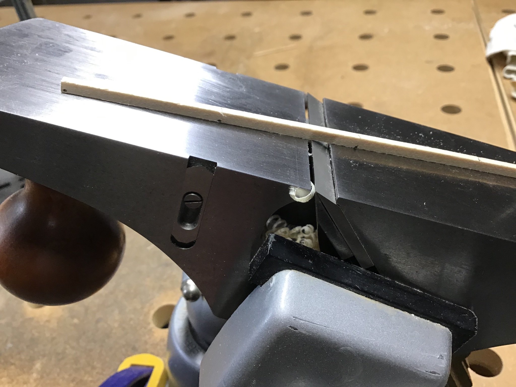
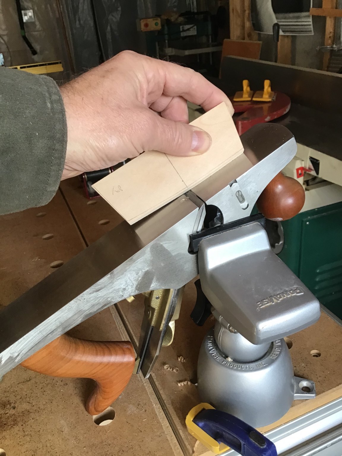
Forgive me if this is repetitive, but I love plank tapering and block shaping, with the plane in a vice, learned that technique from the late Phil Lowe, Master Furniture and Cabinet Maker and founder of the Furniture Institute of Massachusetts.
Happy Labor Day!


-
Welcome and good luck with your project!
- Keith Black and mtaylor
-
 2
2
-
-
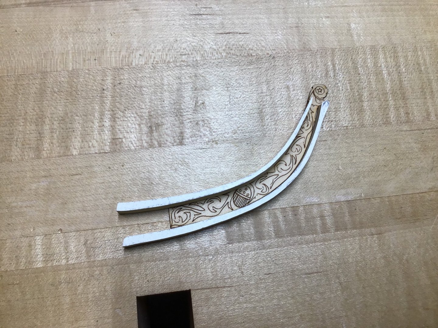
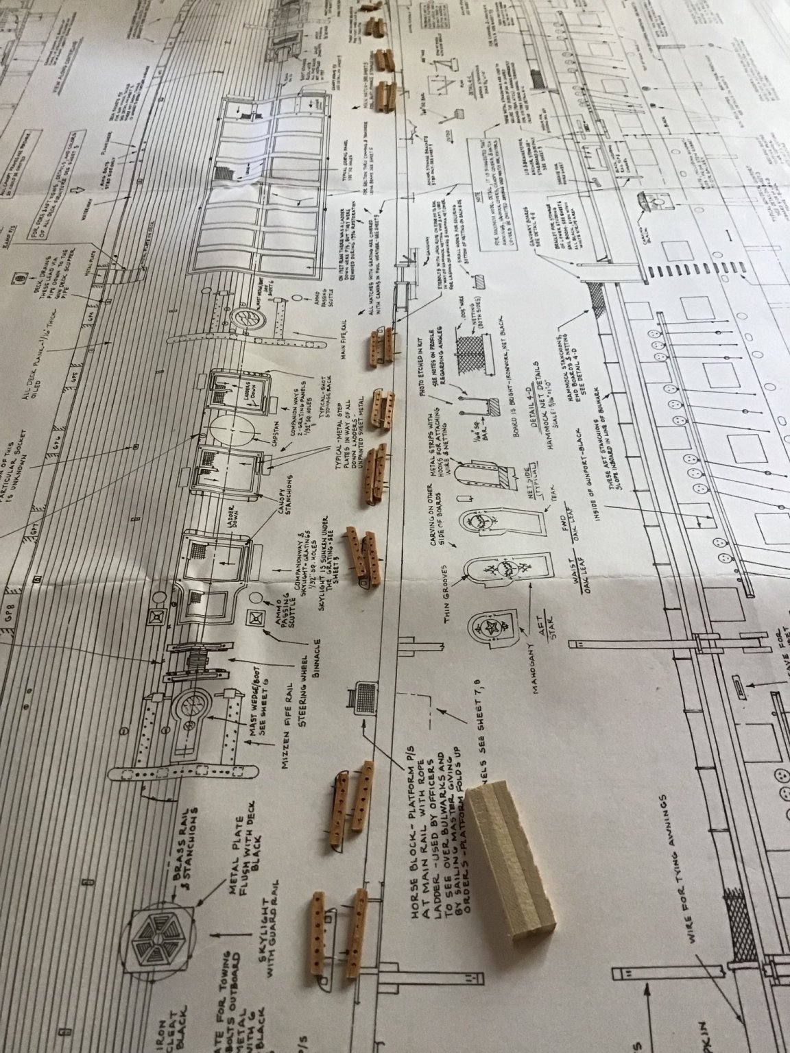
Cheek Knees and Rails - Part 1
Onward to building out the stem detail.
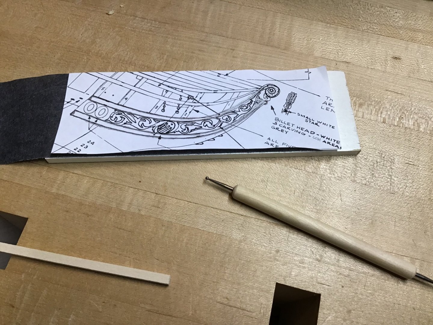
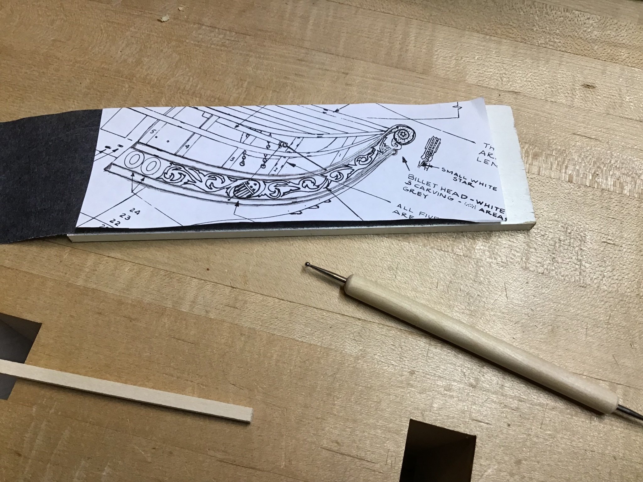
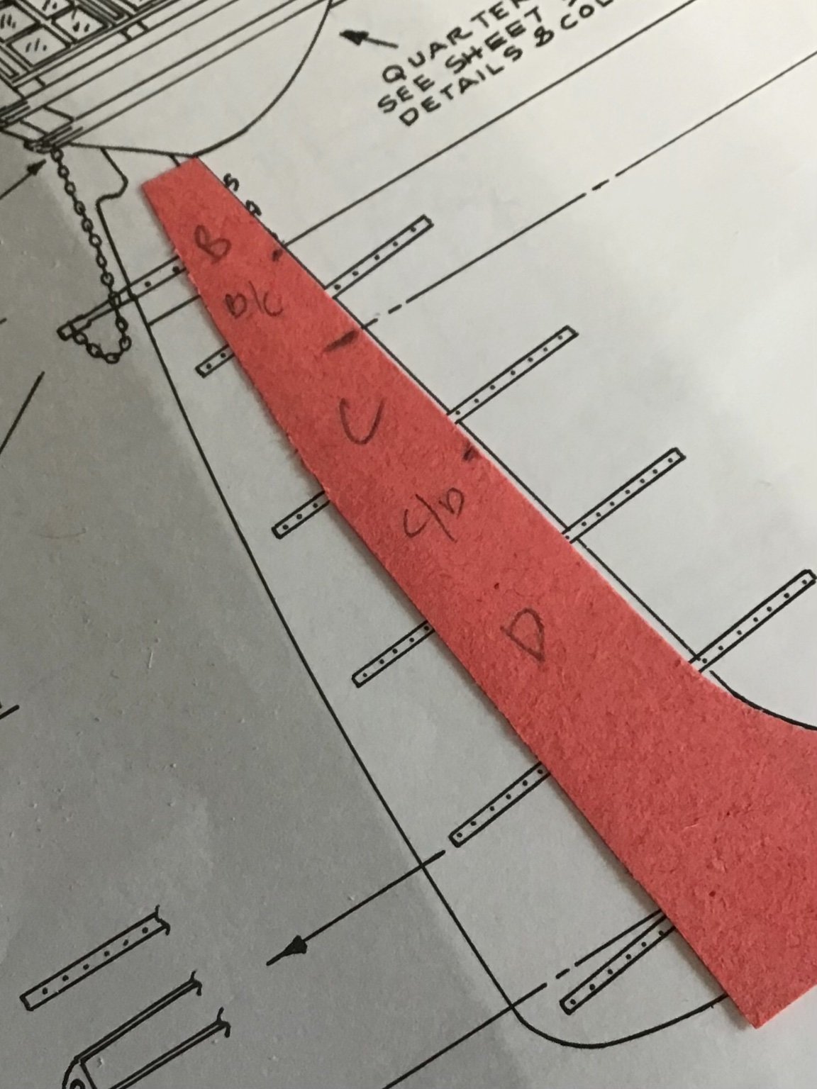
First is to make a template of the cheek knee/rail top view from Plan Sheet 4.
First picture shows a photocopy of the stem area from the plan, on top of a 1/4” thick piece of poplar, with carbon paper in between. A stylus was used to trace the upper and lower rails.
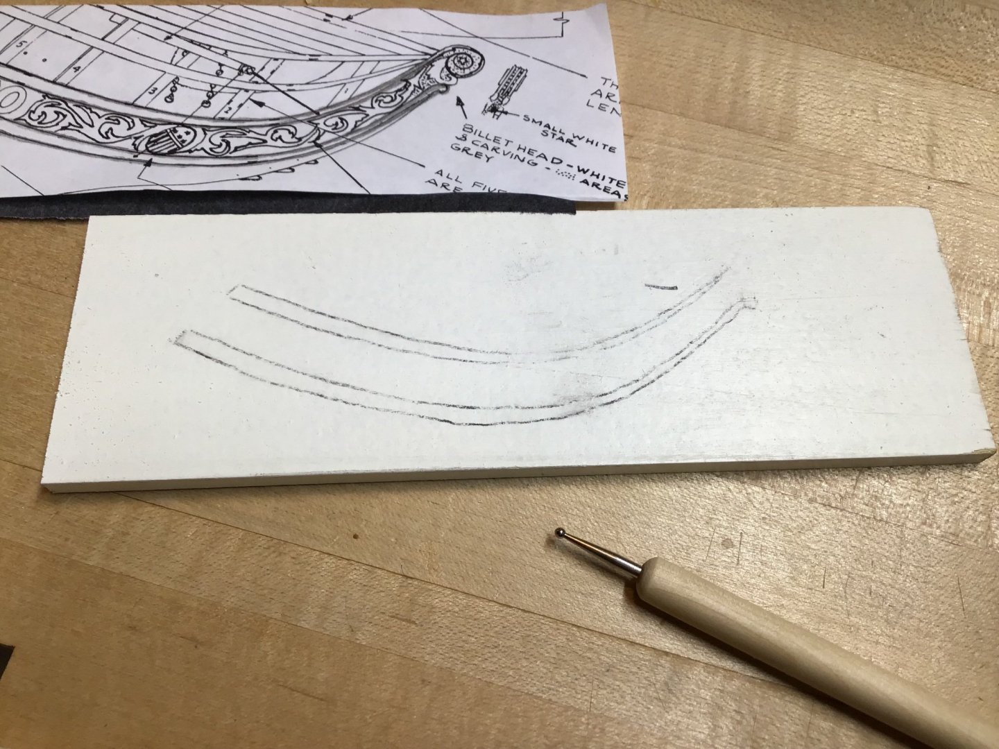
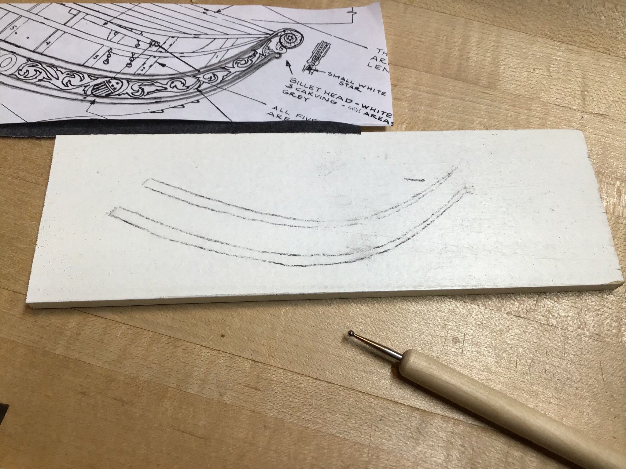
Picture 2 shows the result, a little rough but workable.
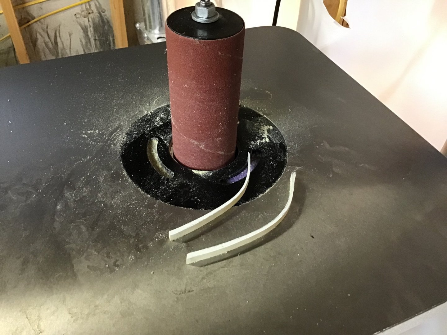
The pieces were cutout with a scroll saw and shaped with the oscillating spindle sander - Picture 3.
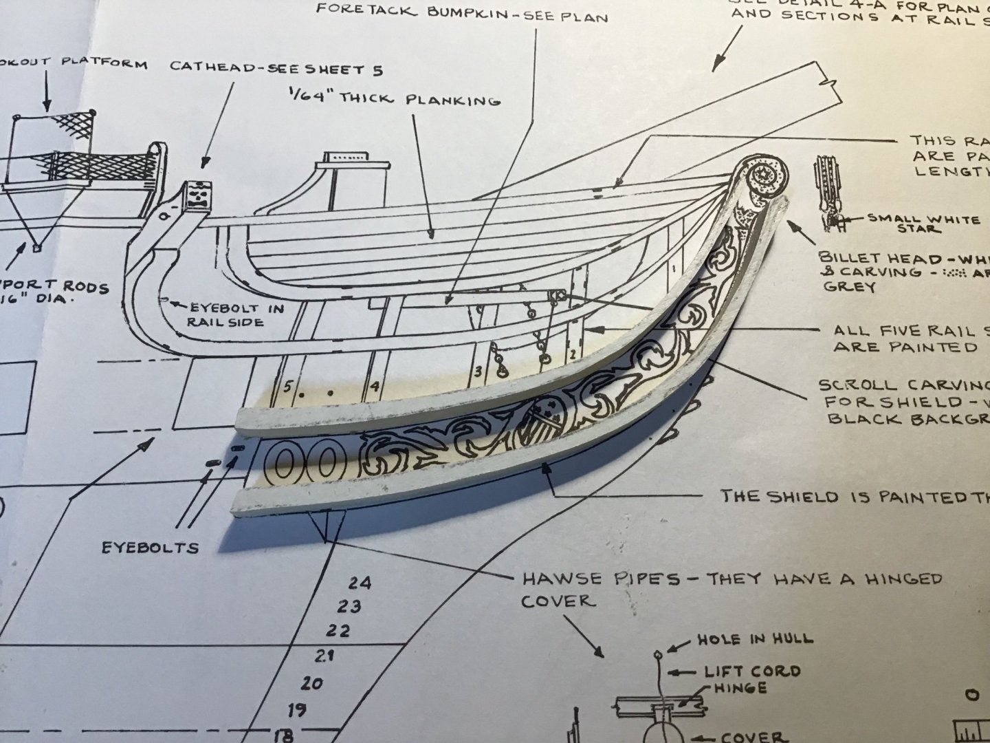
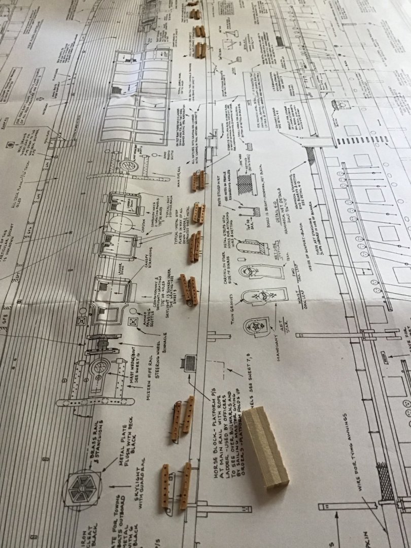
Picture 4 shows the pieces on the plan, note the aft ends are long - the ends will be trimmed to fit the cheek knee pieces.
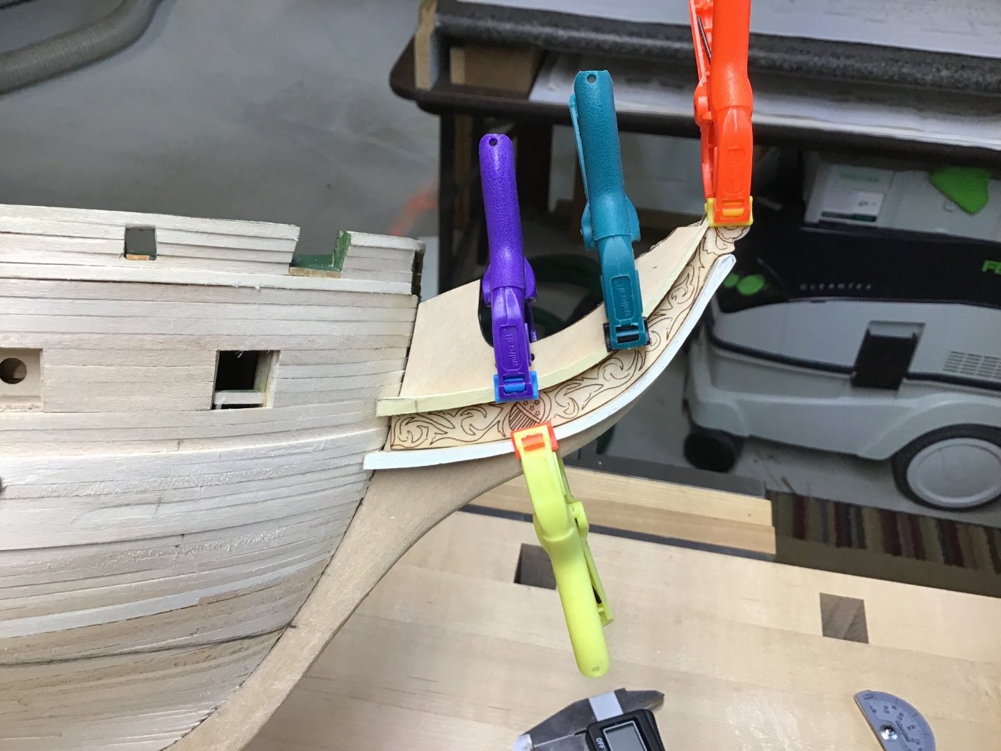
Fit to plan is one thing, but the trailboard edge governs, so the pieces were shaped to fit the trailboard - Picture 5. The tailboard itself is a nice template.
The rails were tapered towards the forward end, also using the spindle sander.
Picture 6 shows the dry fit positioning of the pieces on the stem. The aft ends of the rails need to be shaped and beveled to fit the curve of the hull. Took a while to get it all straightened out - cut one rail to short. Ended up making 6 rails.
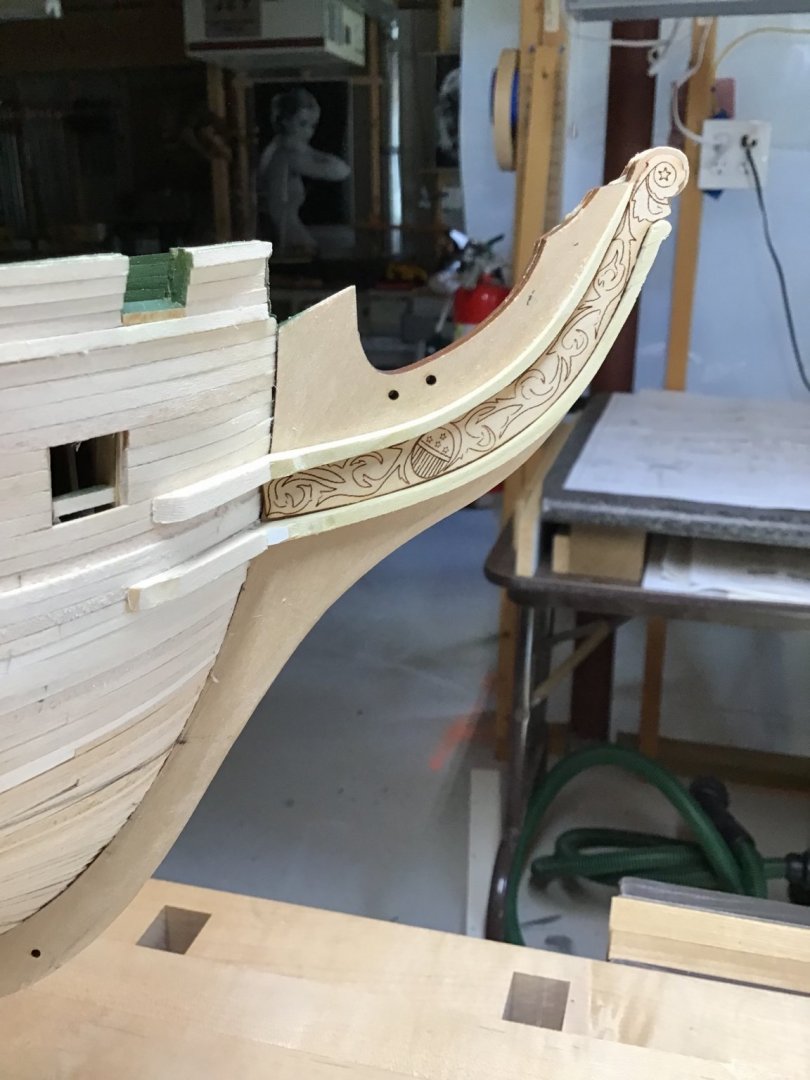
The knee pieces were made using the template from sheet 4. They also need to be shaped and beveled to fit the hull.
Last picture shows everything glued in place. The trailboard is not glued so it can be removed and painted separately.The popular is stiff but brittle and I broke a couple of rails while shaping. The lower rail has a smaller fiddle head on the forward end, after breaking a rail while shaping it, decided to shape the forward end after glueing the rail to the stem.
- Wahka_est, usedtosail, JeffT and 9 others
-
12
-
1 hour ago, BobG said:
Impressive work, Rich!
Thanks Bob.
-
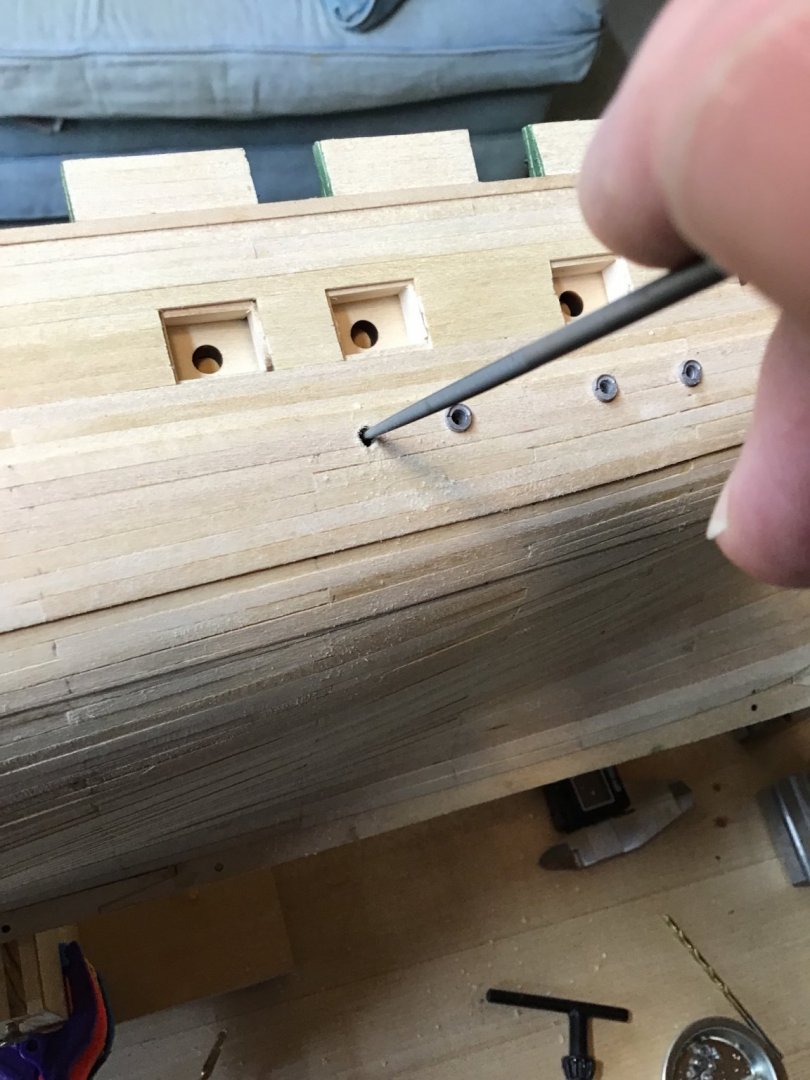
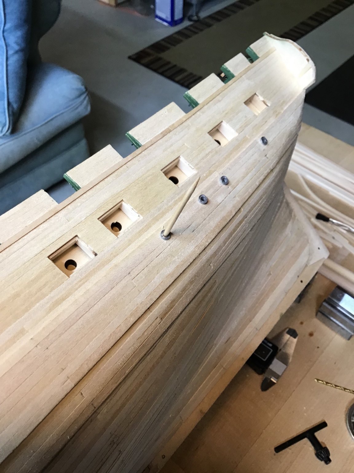
Installing the Berth Deck Portlights and Gundeck Scuppers
We need to drill holes in the wales for the port light and scupper fittings.
First thought was to draw a line with a compass across the hull and mark off the necessary locations.
The most important consideration is we need to get clean holes by minimizing tear-out, sharp bits are essential. So decided the portlight holes would be made in the middle of the second wale strake from the top. The scuppers were installed along the seam between the first and second strake. The portlights have a nice flange to hide a rough edge, but work towards getting a nice clean hole.
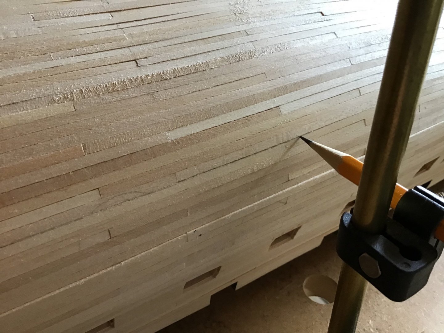
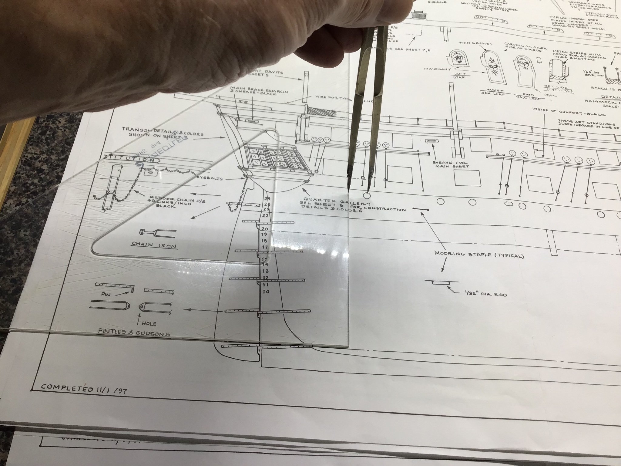
Picture 1 shows a triangle on the plan aligned on the baseline and dividers measuring the distance from the forward edge of the last gunport to the aft portlight. The dividers were then used to mark the location of the aft portlight on the second wale strake.
Picture 2 shows how subsequent hole locations can be marked based on the distance between portlights and always in the middle of the second wale strake from the top of the wale.
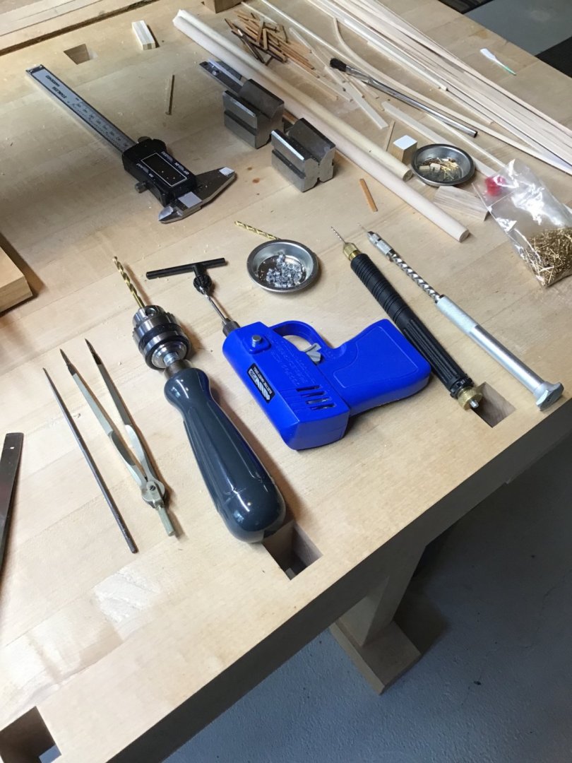
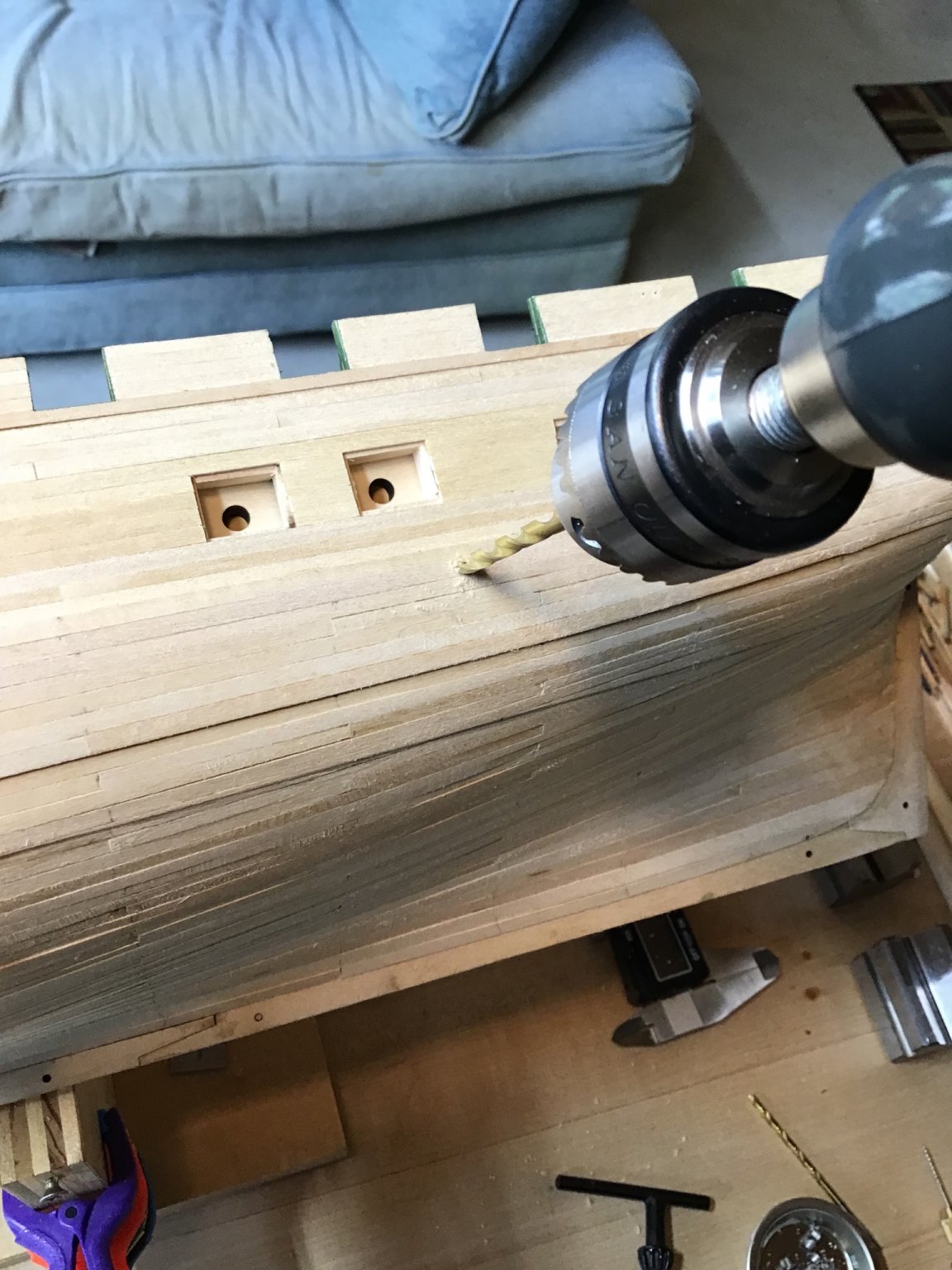
Use progressively larger bits to drill the hole. Picture 3 shows the tools with smaller bits on the right to the final size bit on the left.
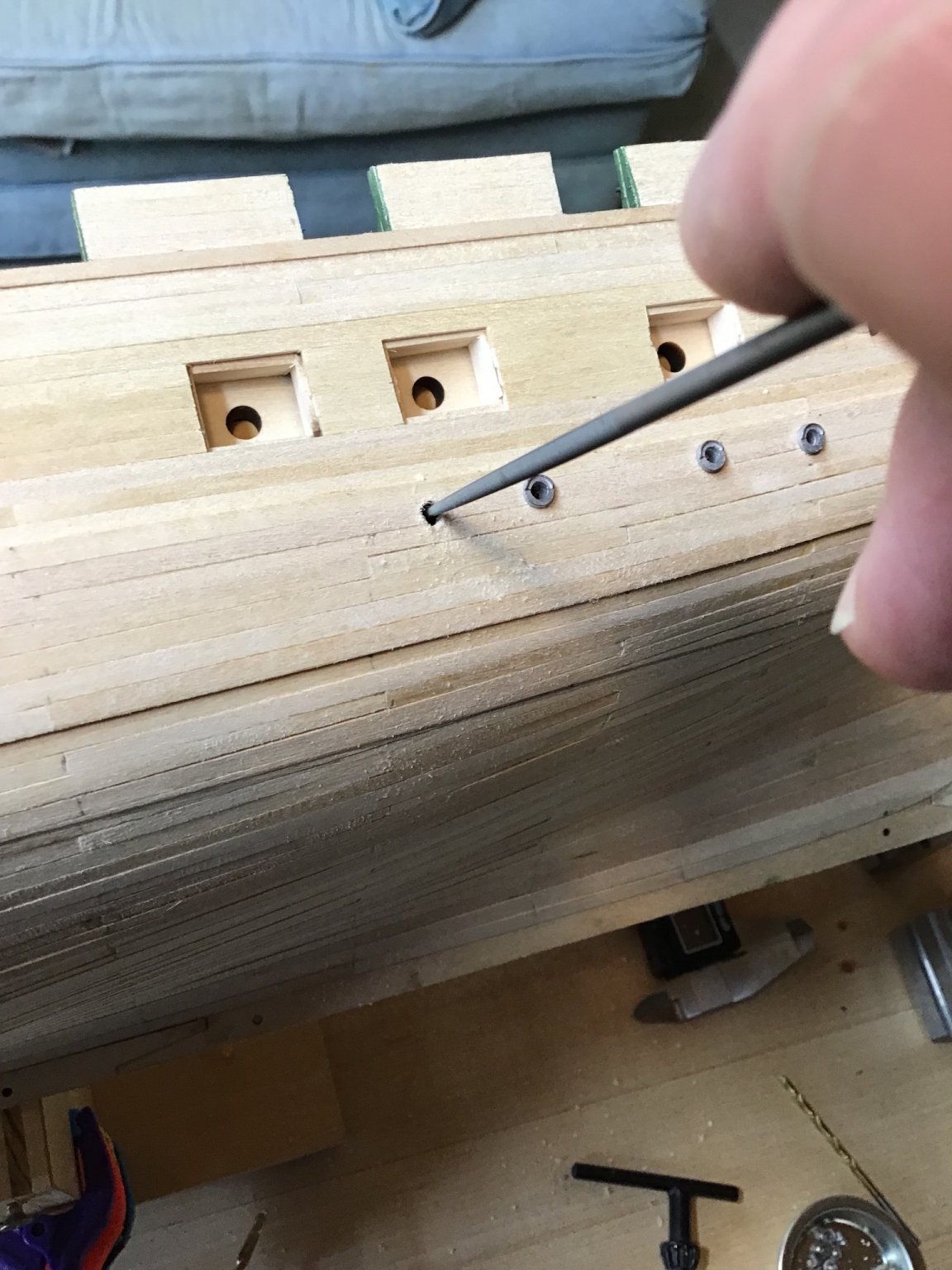
Picture 4 shows drilling the final hole by hand. Take care, start by turning the tool to the left to compress the fibers around the hole. Then turn to the tool to the right to enlarge the hole, and occasionally to the left, to again compress the fibers.
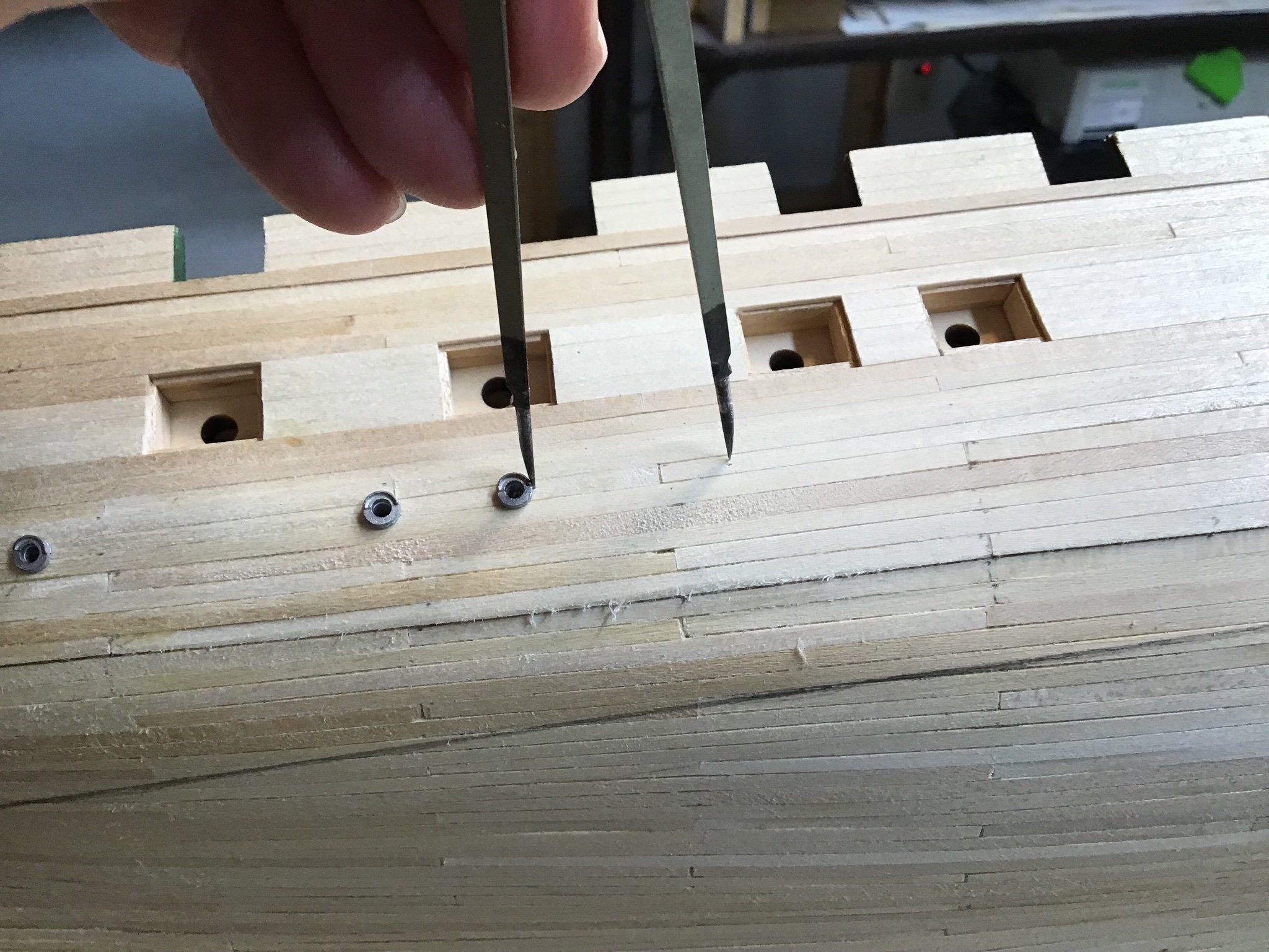
A round file can be used to cleanup the hole, Picture 5.A toothpick can be used to help with installation Picture 6. The adhesive is a tiny bit of epoxy.
Last picture shows the lights and scuppers installed on the starboard side.


-
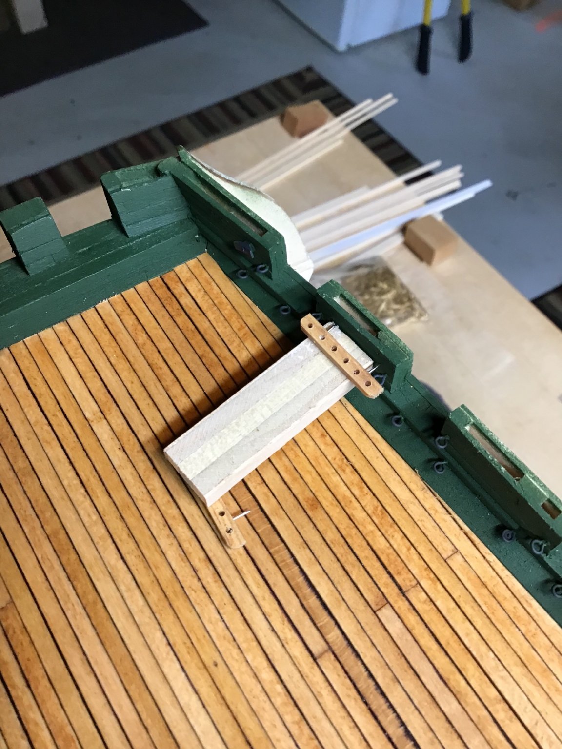
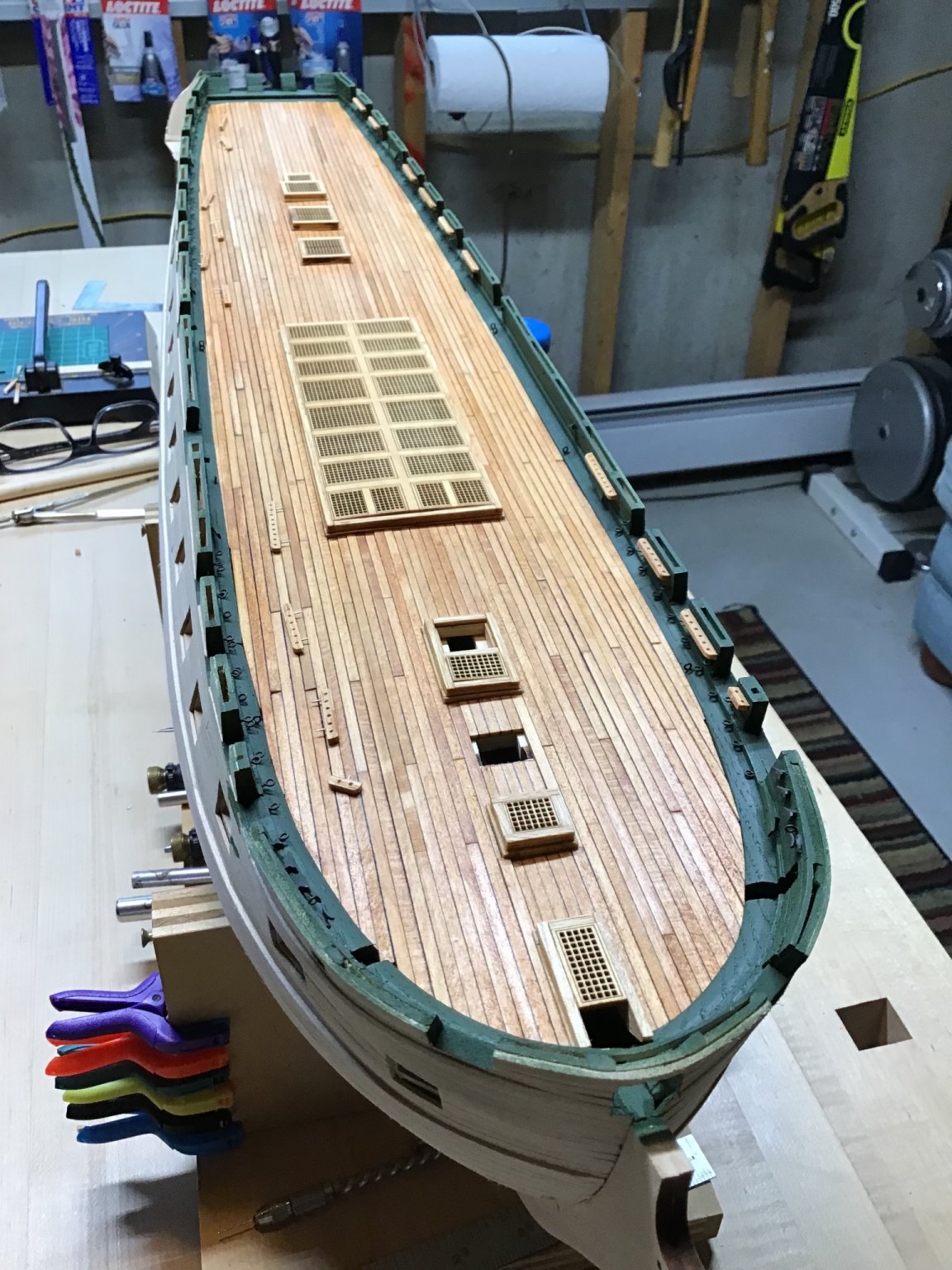
Making and Installing the Pinrails
Stained stock and drilled the holes along the stock with the Foredom drill press.
Then cut the stock to length and drilled two holes and installed 2 pin nails in each piece, with points out. Pieces were placed on the plan to keep track.
Pinrails are located 7/32” above the top of the waterway, so made a spacer block to help with positioning. Then it was just a matter of pressing the pinrail into the bulwark, with a bit of glue along the edge.
Last picture shows rails installed on the port side, with pieces on the starboard side ready to go.


- BobG, GrandpaPhil, HIPEXEC and 3 others
-
6
-
-
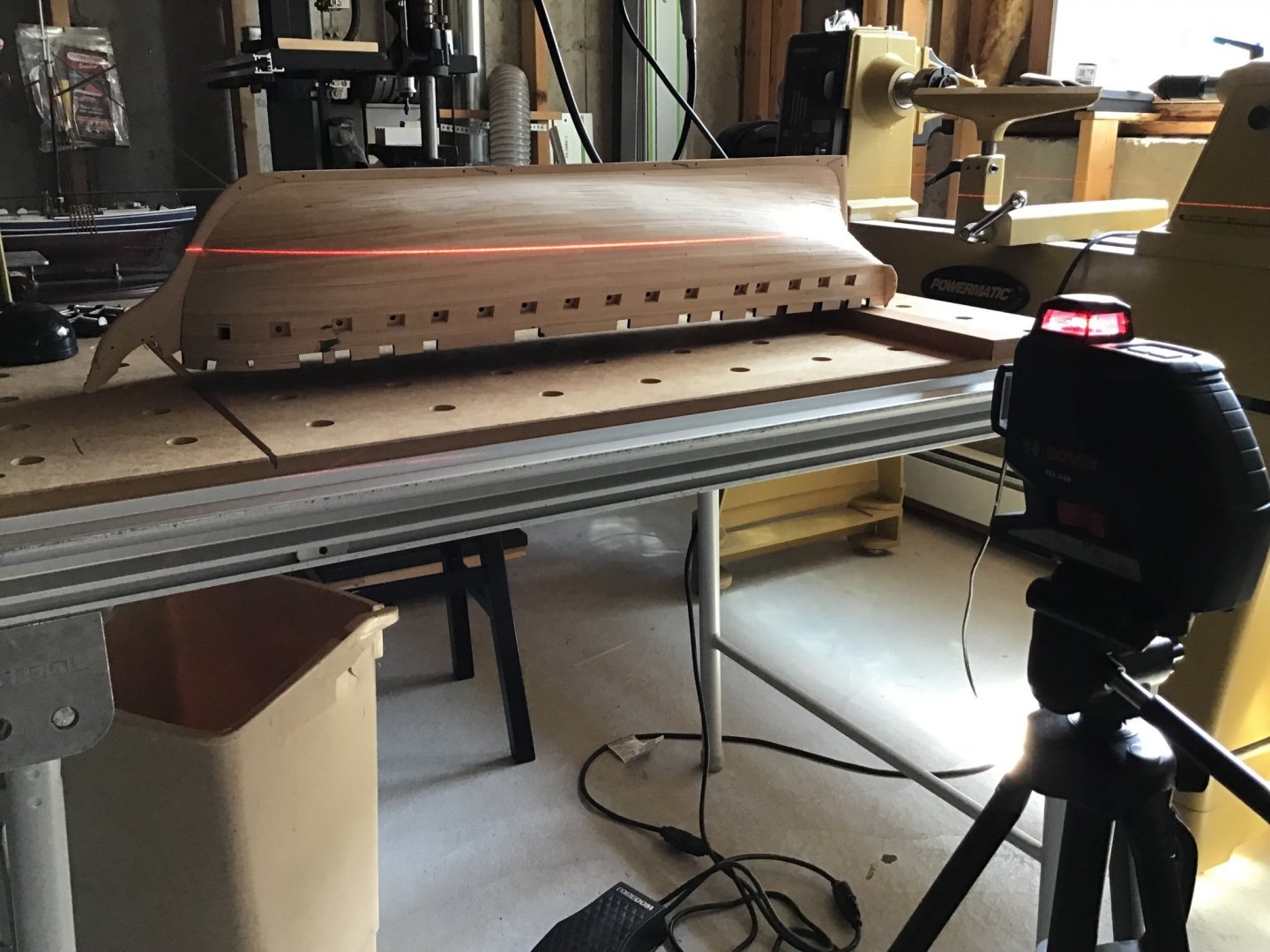
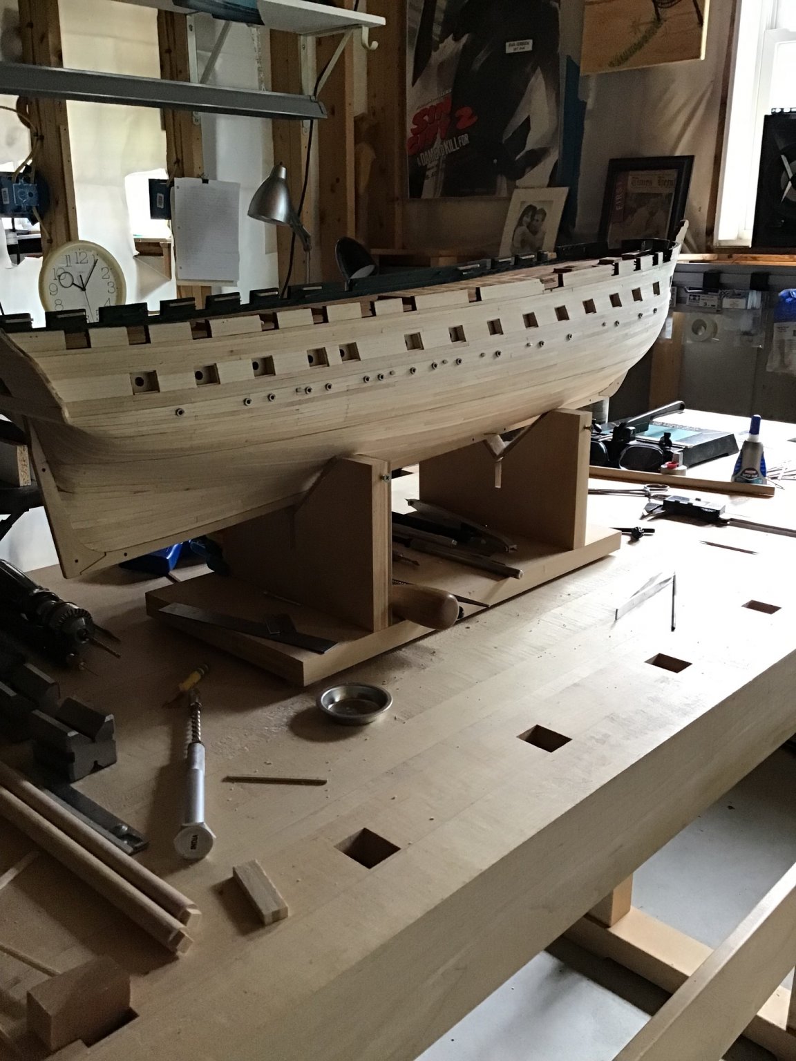
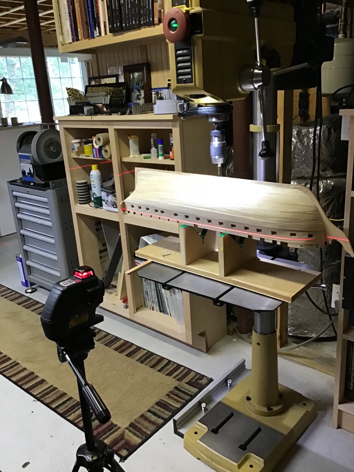
Drilling Keel Mounting Holes
Now that the waterline is marked, it can be used to setup the drill press for drilling 2 pilot holes, for the mounting screws, in the keel. Will probably use a cradle but maybe pedestals. TBD.
Again used the laser level, and shimmed the cradle level. Drilled a small hole first, then the final hole corresponding to the screw root diameter.

- BobG and GrandpaPhil
-
2
-
Hi Jason,
Just noticed your log and the way the work is progressing, for a first project, is remarkable. Good for you.
Coming late into this as the planking as almost complete.
Going forward take a look at proportional dividers for measuring plank widths. Fast and autocorrects for errors. Checkout my USS Constitution build log. The dividers are a huge time saver.
When planking I like to use a dot of CA on the bulkhead, and elmers carpenter glue on the edges, this gives a quick hold without clamping.
Planks should lay easy along the bulkheads with very little if any edge bending required - if edge bending is necessary or a clamp is needed to force the plank against it’s neighbor most likely the plank is too thick at one bulkhead or two - there is a tapering issue.
Your experience with the butt joint spacing is par for the course, the “correct” spacing is a goal, but in practice it’s not possible to maintain across the entire model.
Obviously you have a high standard for your work. Notice though, when the model is upright that lower hull minor imperfections will not be noticeable.
Anyway, hope this helps. Again, nice job, looking forward to following along.
-
Hi Chuck, greetings from Massachusetts welcome to MSW!
- mtaylor and Keith Black
-
2
-
Hello and greetings from Massachusetts USA. Feel free to ask a question, and good luck with your project!
- mtaylor and Keith Black
-
2
-
Hello and welcome! Good luck with your project. Always around if you have a question.
- mtaylor and Keith Black
-
2
-
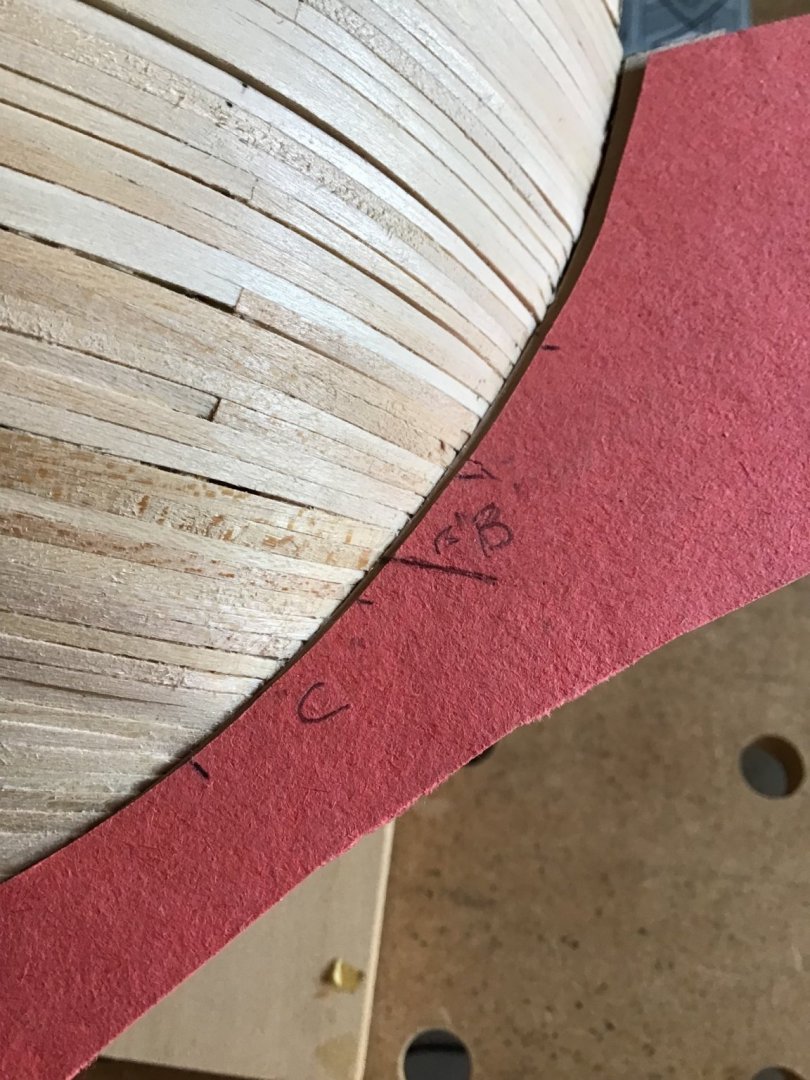
The Road Ahead and Marking the Waterline
At this point we are working towards the milestone of prepping and painting the outer hull.
The sequence will be: making the hull penetrations for and installing the hawse lips, deck lights, and the scuppers; building and hanging the rudder; and last building the stern galleries and head works.
The big idea is, to minimize damage from handling, the galleries and head works will be built last.
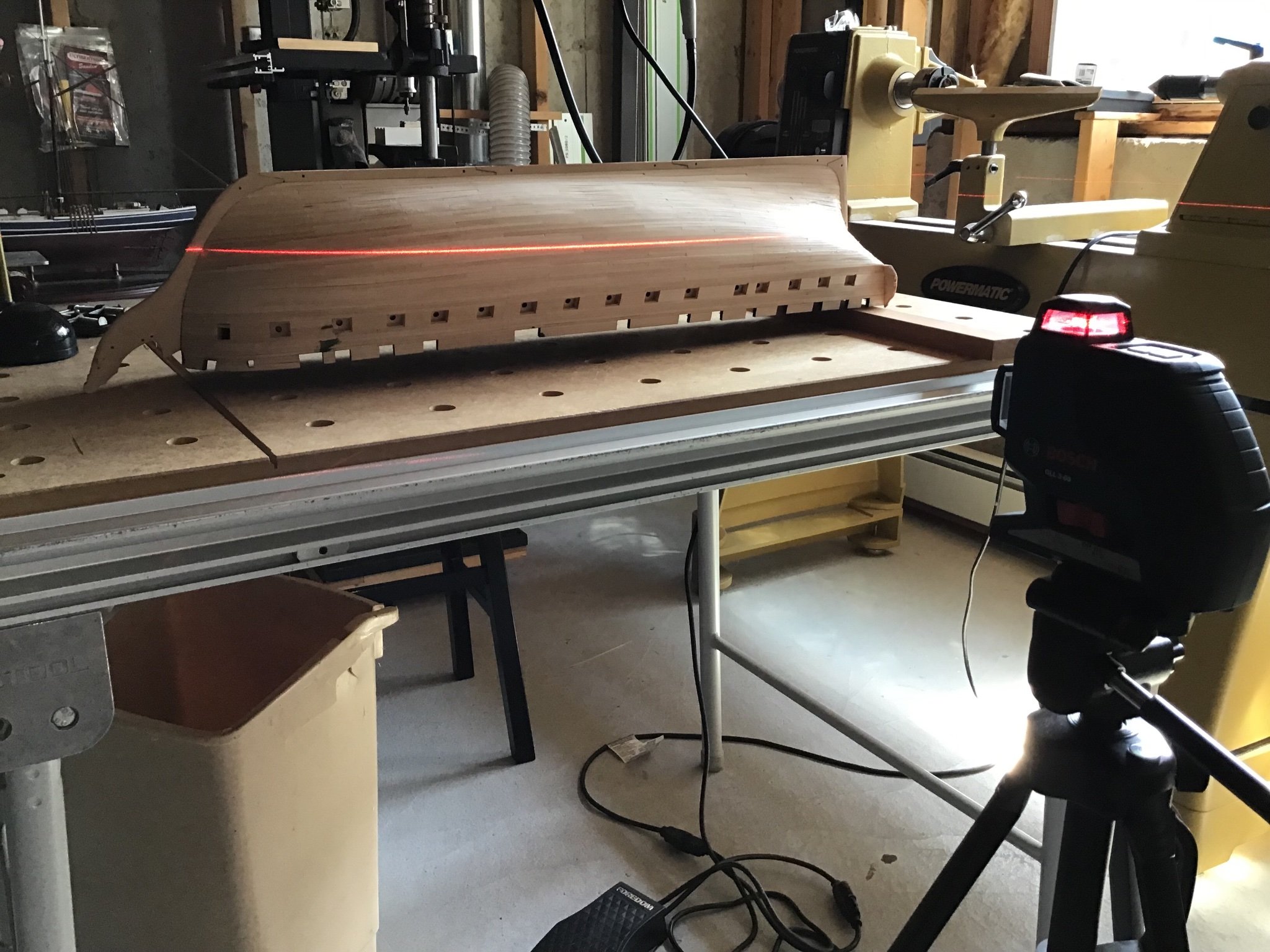
To mark the waterline, first templates were made and used to locate and mark the waterline on the stem and stern posts.
The hull was placed upside down on the bench and a laser level and a block used to level the marks made on the stem and stern post.
Last a waterline was drawn connecting the dots, with the Amati tool.

- Sea Hoss, GrandpaPhil and BobG
-
3
-
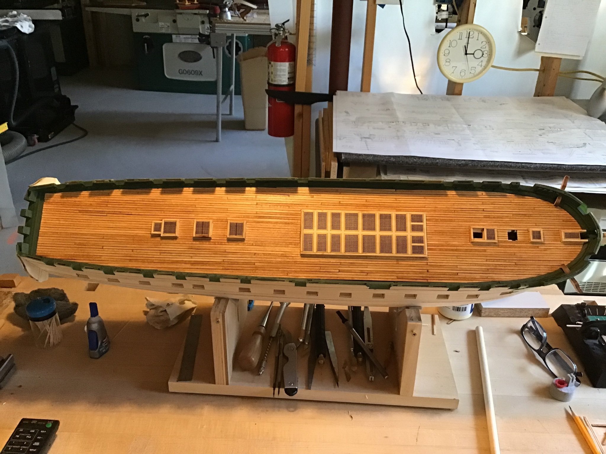
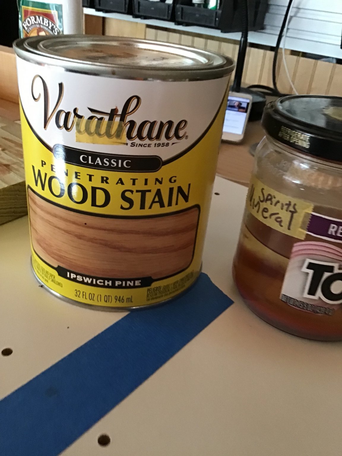
Deck Finish Update
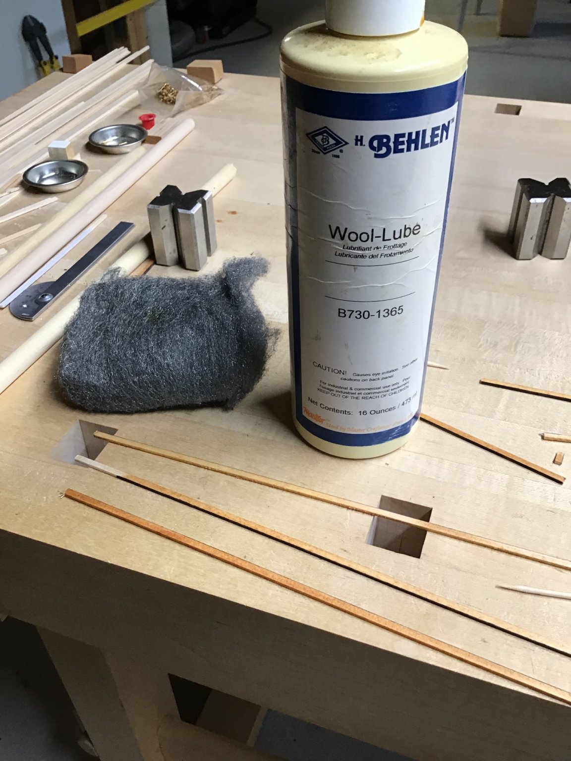
Worked the finish with the steel wool and wool lube. After, applied several additional coats of stain, I like Varithane Ipswich Pine.
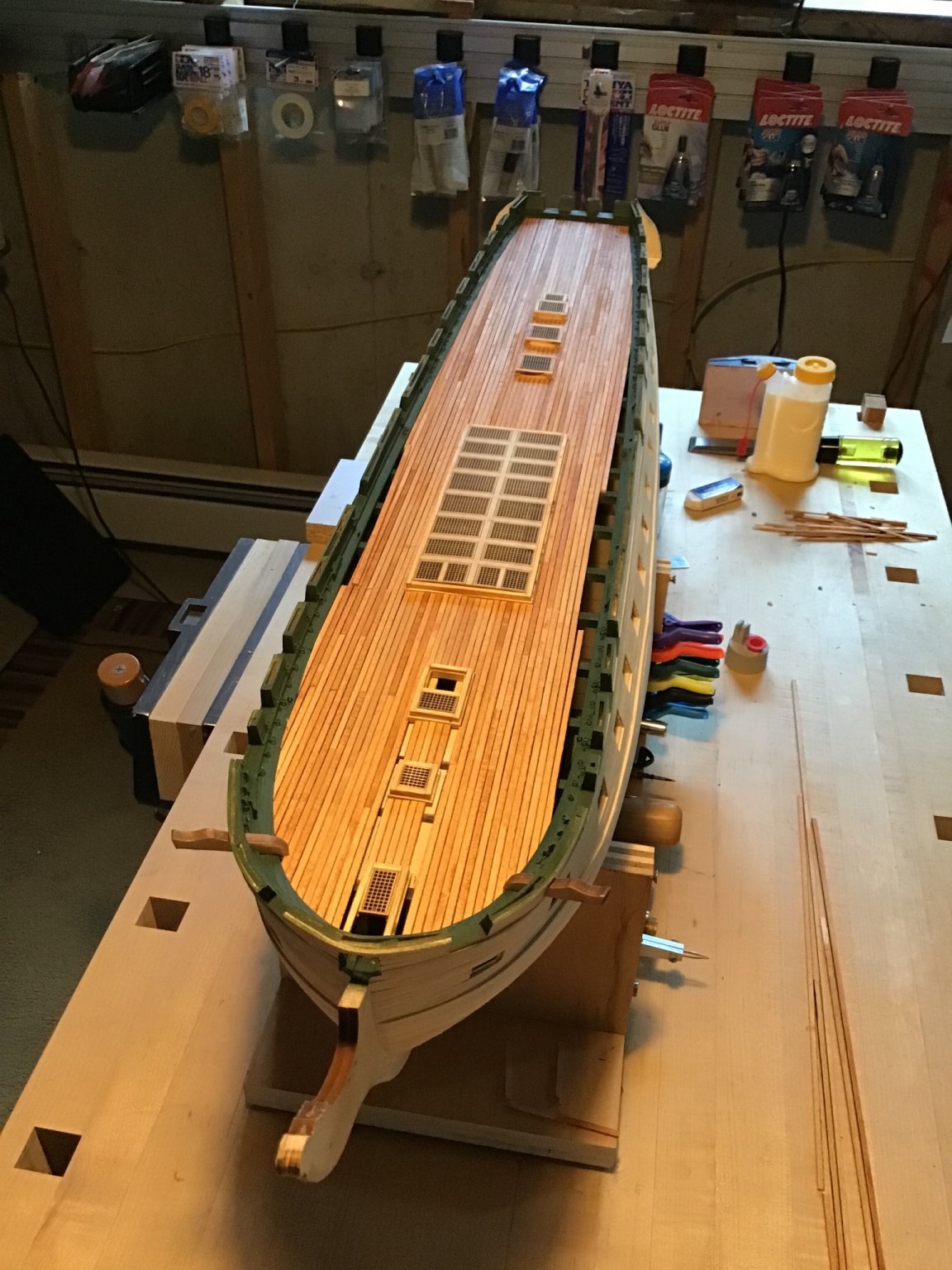
Here is how it’s looking at this point. Probably a few more applications to go.


- Sea Hoss, BobG, GrandpaPhil and 3 others
-
6
-
Checkout this video from Lie-Neilson Tools up in Maine….
-
Hi Avi,
Thanks for the mention. Read through your log, and I’m going to follow along with interest.
Like the way you are using templates and pencil lines.
Hope you don’t mind a couple of thoughts.
Noticed the mention of chisels and gouges in the last post. How is it going with “sharpness”? Are you able to get a razor sharp edge on your tools?
When I first started out it took me a while to realize that I had to learn how to sharpen my tools. Sharp tools make life a whole lot easier. Saves a sore wrist from sanding as well.
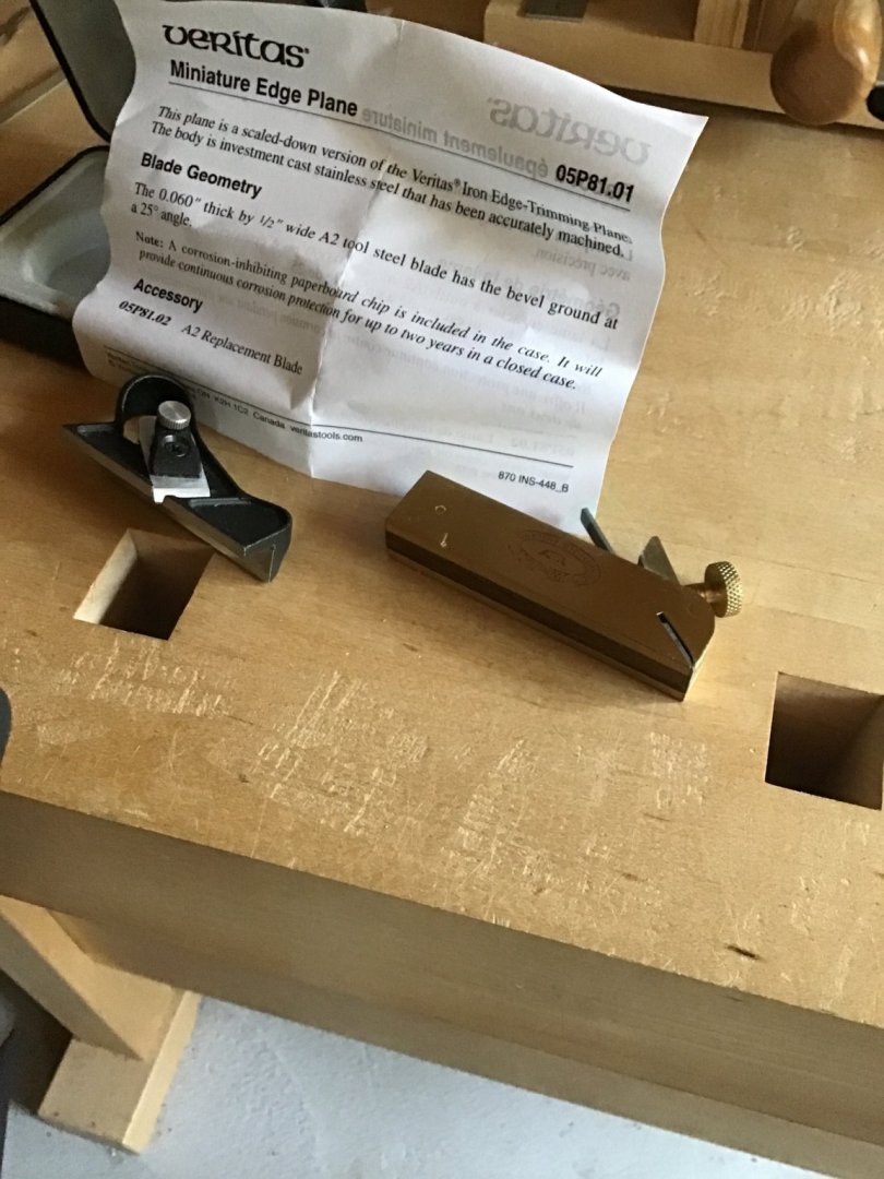
Regarding the bulwarks. Mini planes are a big help. Lee Valley tools offers a collection of mini tools including the edge plane, on the left in the photo below. On the right is a bull nose plane.
It looks like the project is going well, best of luck and may your problems be small!
-
Keep going you’ll get the hang of it! I use CA applied with a pointy toothpick. Just a tiny dab at the location. Dries clear.
Good luck with it….
- Organ tech and Tigersteve
-
2
-
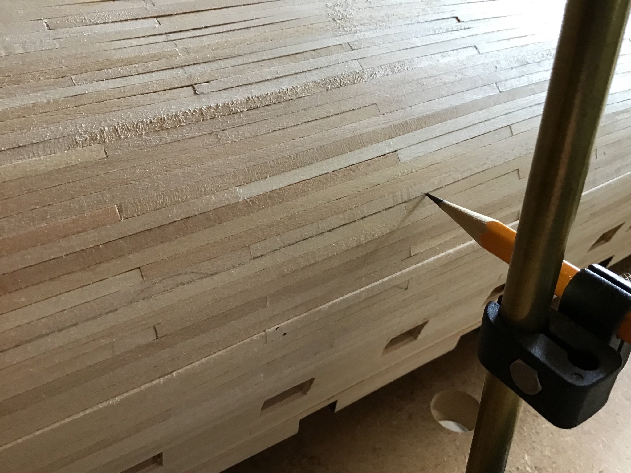
Evening Deck Finish Color
There is a little to much variation in the stain across boards. The darker boards have dried stain.
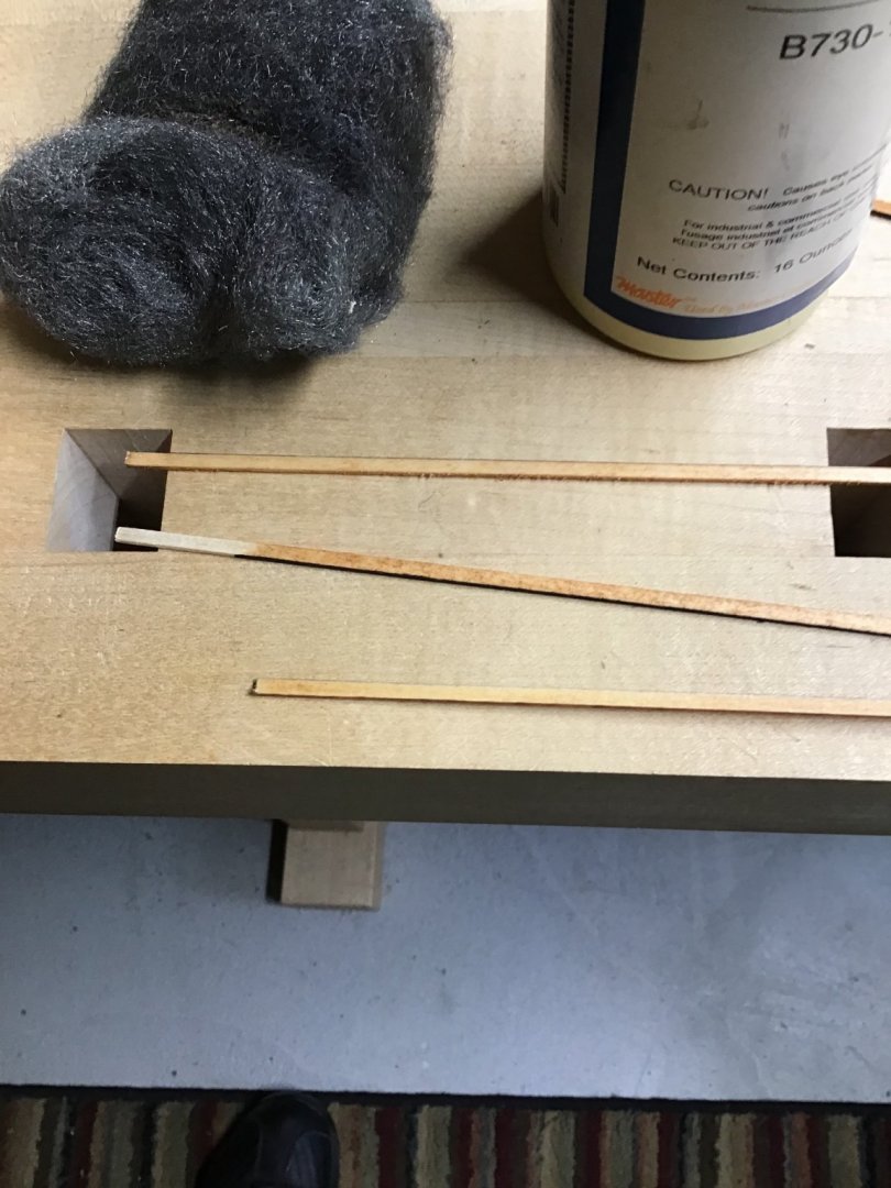
To address the issue steel wool can be used to remove stain.
I like to use a product called “Woollube”. It’s a lubricant for steel wool. Just a dab on the steel wool pad is needed.
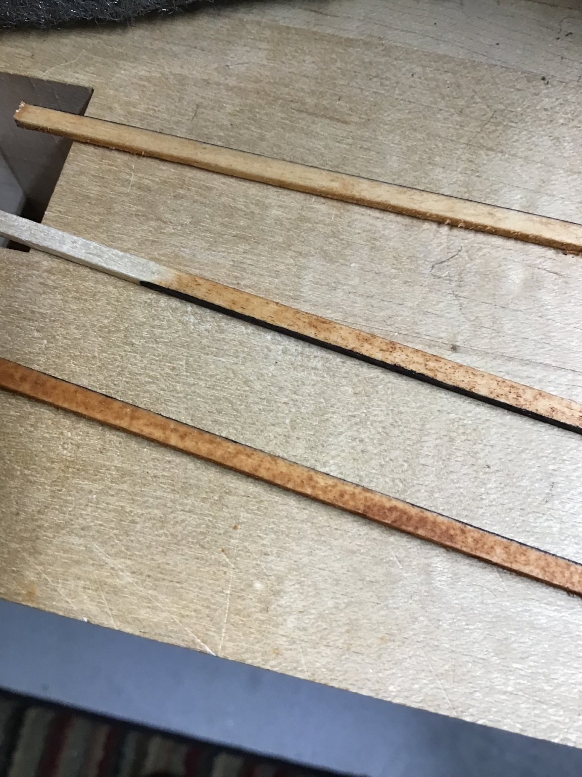
Photo 1 shows 3 boards in the lower left with the over-stained board at the bottom.
Photo 2 is a closeup, with the over-stained board at the bottom.
Photo 3 shows the over-stained board after rubbing down with the steel wool pad and Woollube.
Plan is to use this process on the entire deck.


- BobG, GrandpaPhil and Duanelaker
-
3
-
On 8/20/2021 at 10:04 PM, BobG said:
Beautiful work, Rich!
16 hours ago, Avi said:Wow @ERS Rich that spardeck is beautiful!
Thanks guys! A little unhappy with the stain variation between boards. A couple of things, pine takes stain unevenly, and some of the stock should have been wiped down before the stain dried.
The next post shows how to address this issue….
-
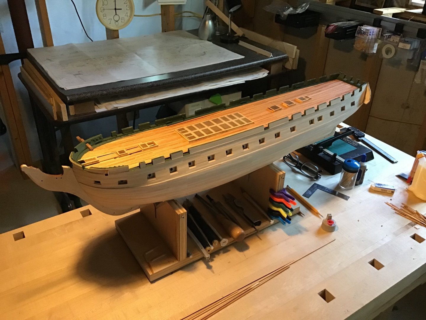
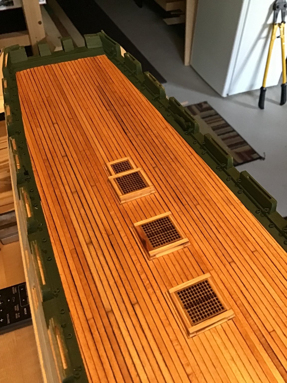
Planking the Deck - Part 4
Just a few shots - almost complete.

- usedtosail, Avi, Boatsinc2000 and 7 others
-
10
-
Handsome ship, thanks for posting….
- Egilman, popeye the sailor, mtaylor and 1 other
-
4
-
Greetings from Massachusetts, USA. Always open to answering a question. By the way, that’s the Sydney skyline in the background of my profile picture. Cheers!
- mtaylor and Keith Black
-
2
-
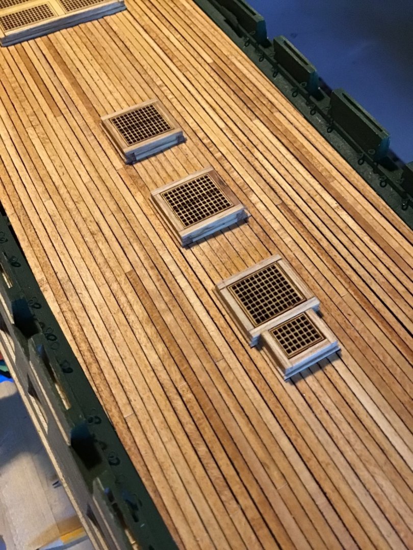
Planking the Deck - Part 3
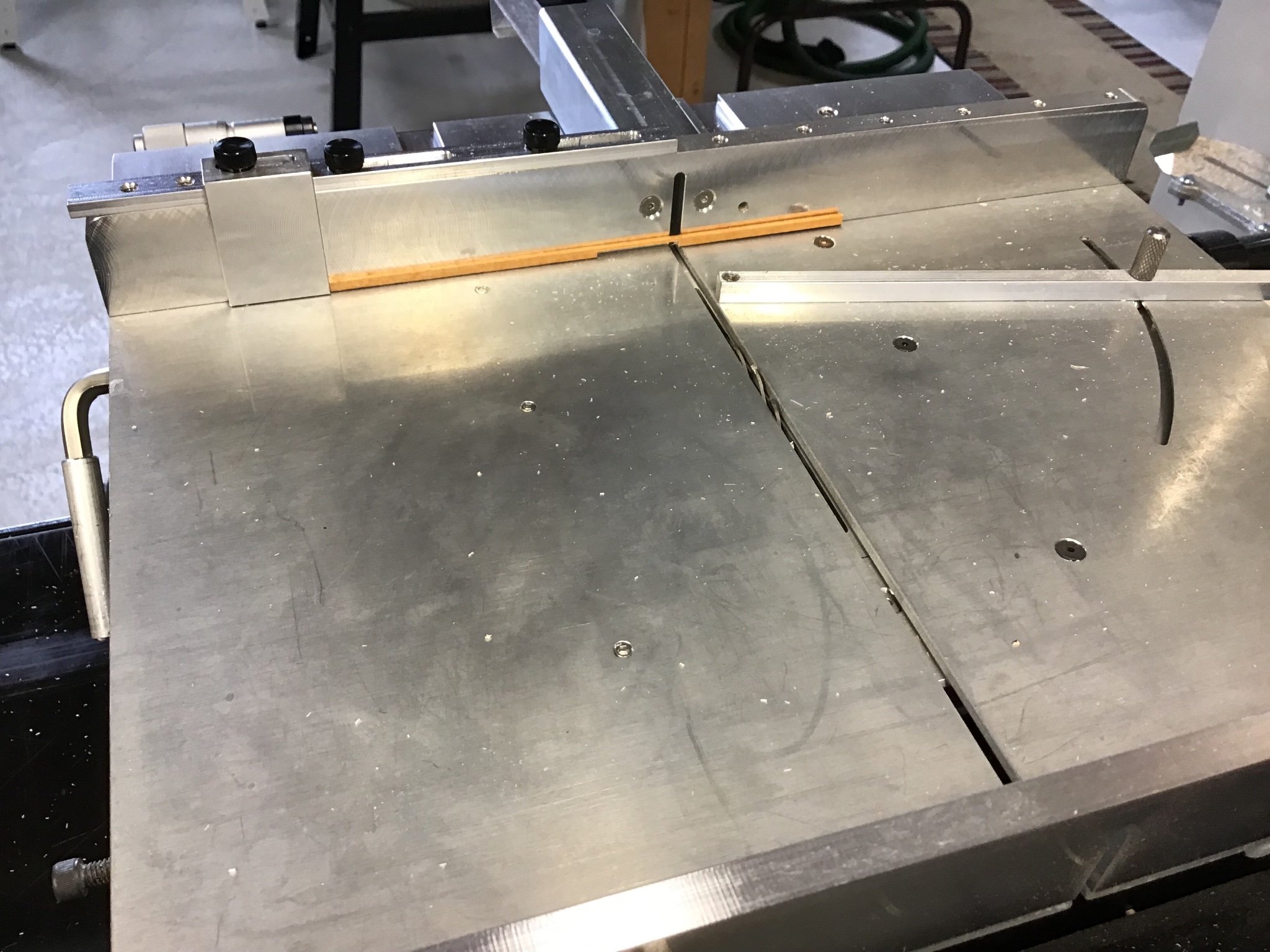
This work is an exercise in using the table saw with the fence and stop cuts. Detailed instruction on table saw use is beyond the scope if this log, there are plenty of free videos out there.
The task at hand is to make multiple notches in a board to fit around two hatches.
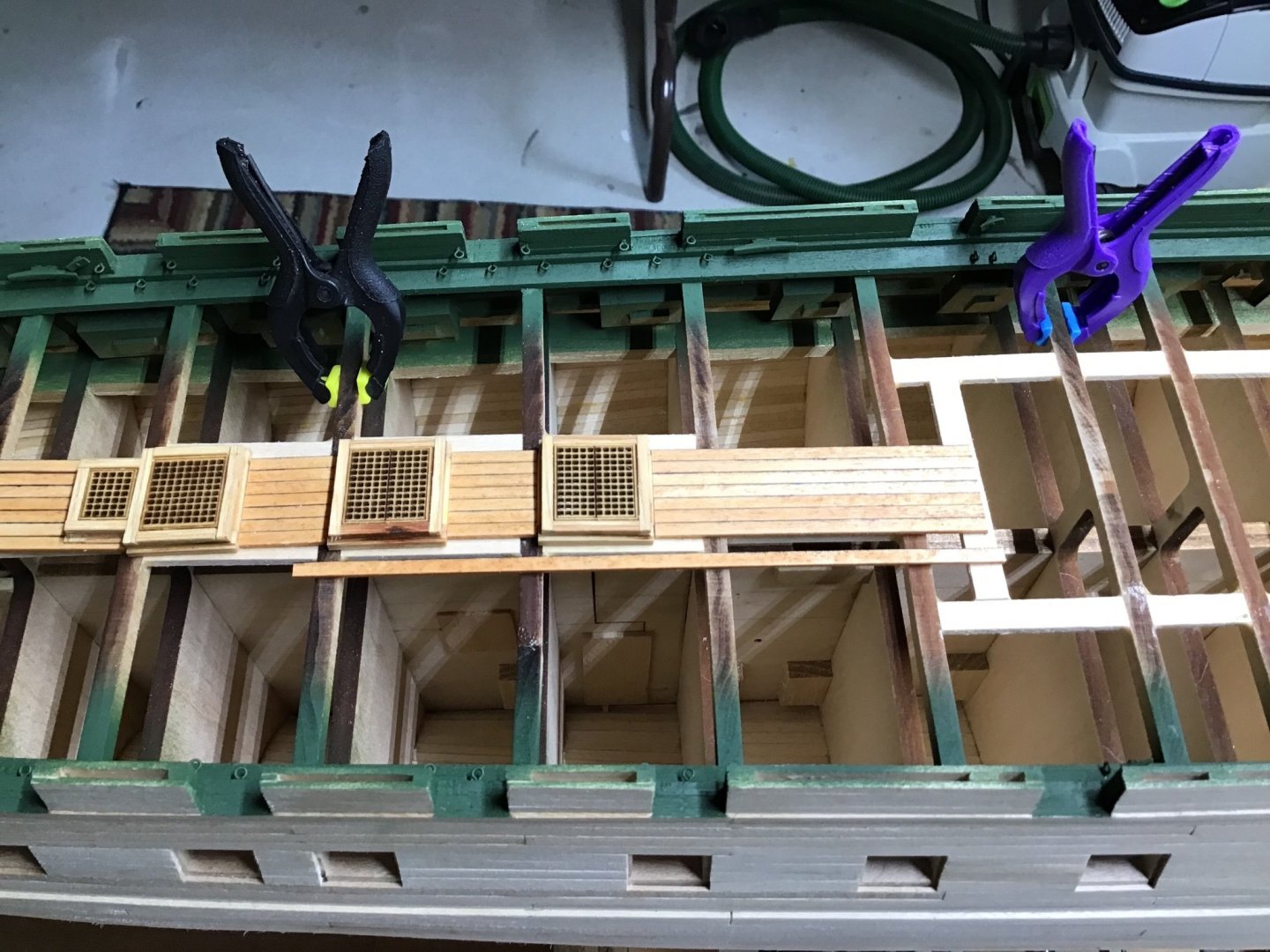
As before start with a longer board that overlaps the end points. Picture 1.
Notice we need a notch in the middle and at the aft end. The middle notch has 2 corners and needs to be 31/32” wide to fit around the coaming, while the aft notch is open ended. and space between the notches is 49/64”.
The notch depth is the same as the previous post, no need to change the blade height.
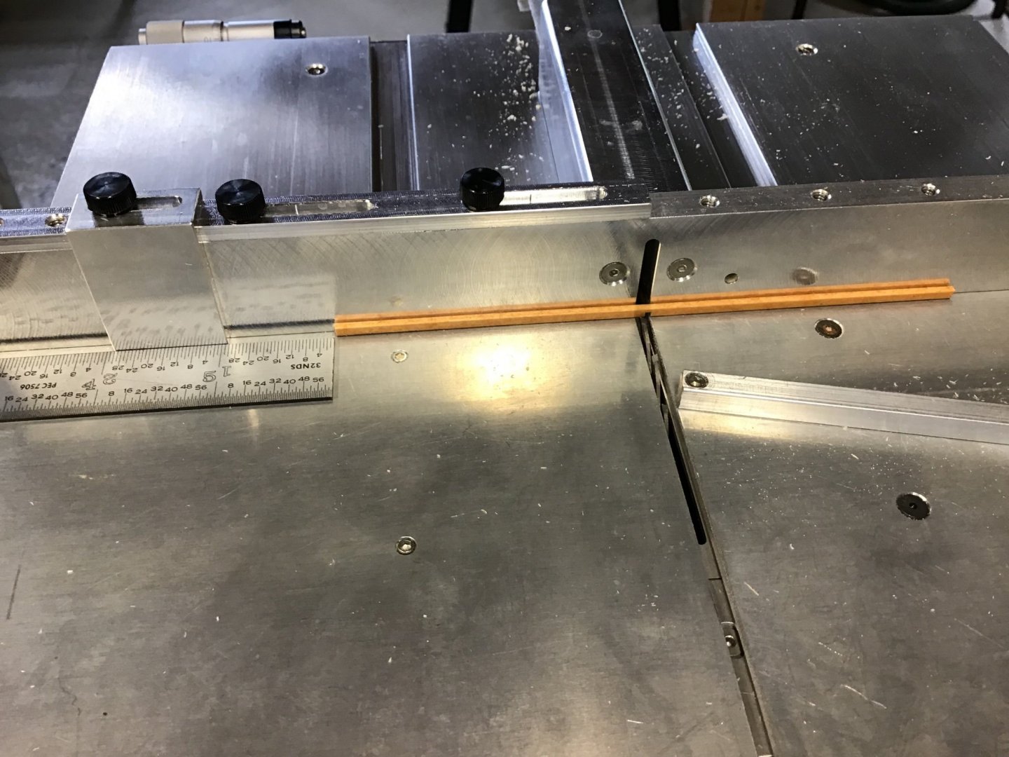
Picture 2 shows a pencil mark to locate the forward end of the middle notch.
Picture 3 shows the board on the saw with a cut at the pencil line. And to the left, a steel rule is used to set the end stop and define the width of the cut. Important take the blade width into account. My first attempt resulted in an override cut because I forgot to subtract the width of the blade when setting the end stop.
Also set up the end stop a little short, then sneak up on the final cut.
The aft notch is done in a similar manner.
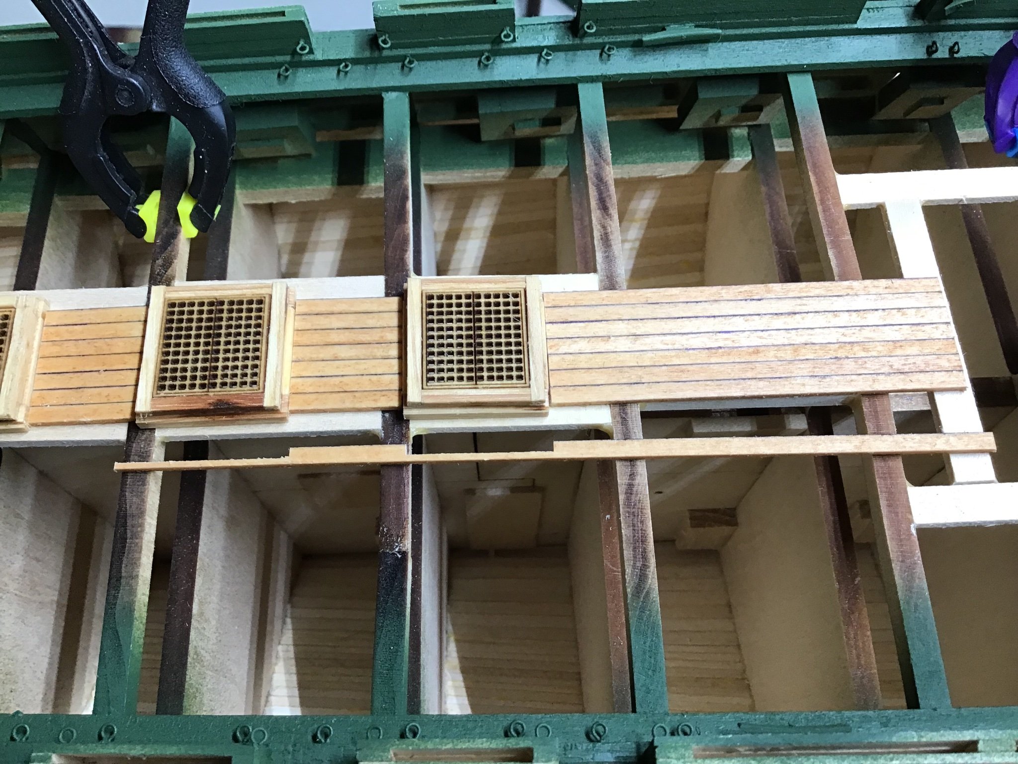
Picture 4 shows the board after cutting with it’s end up against the stop.
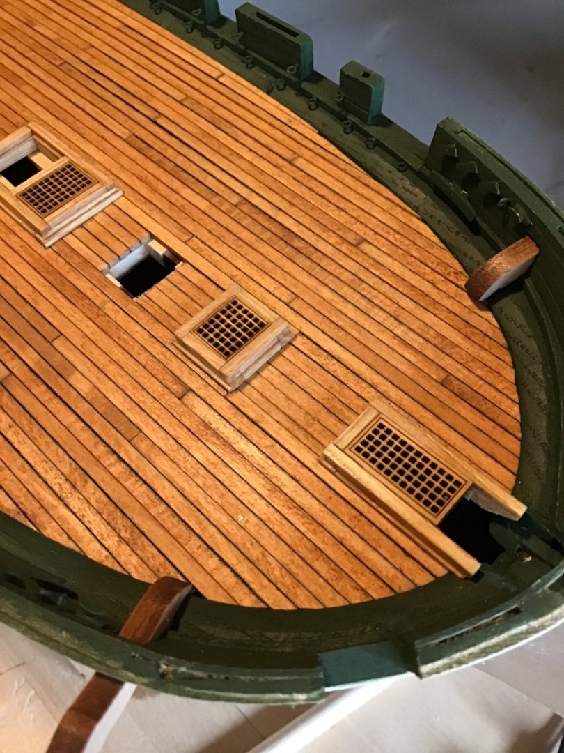
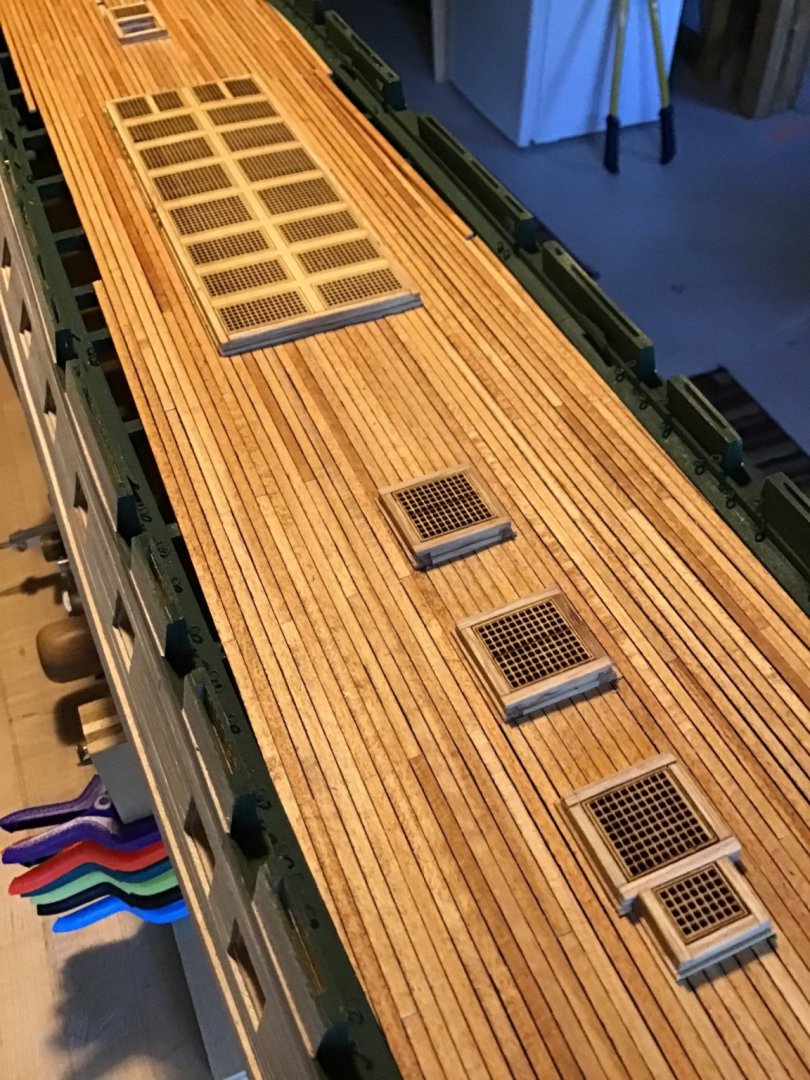
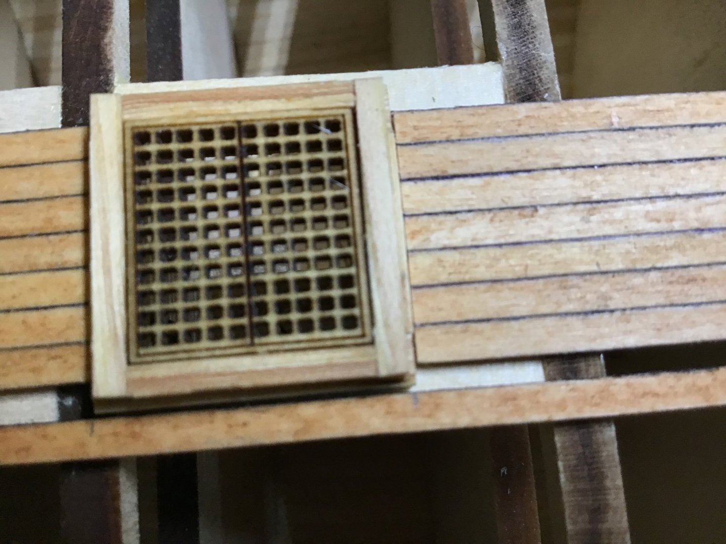
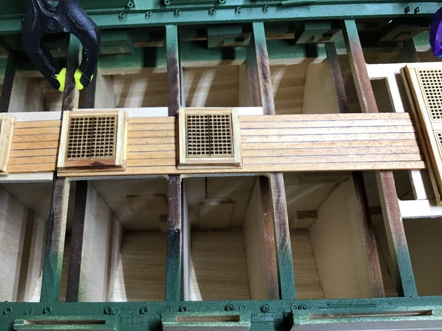
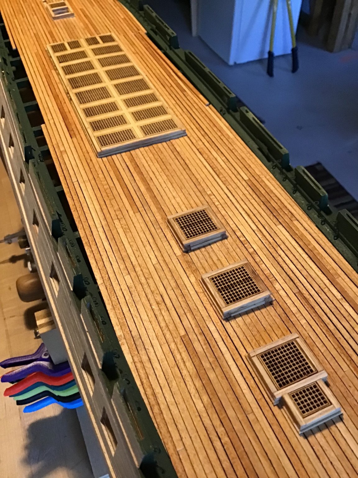
Picture 5 shows the board in position, with the two notches.
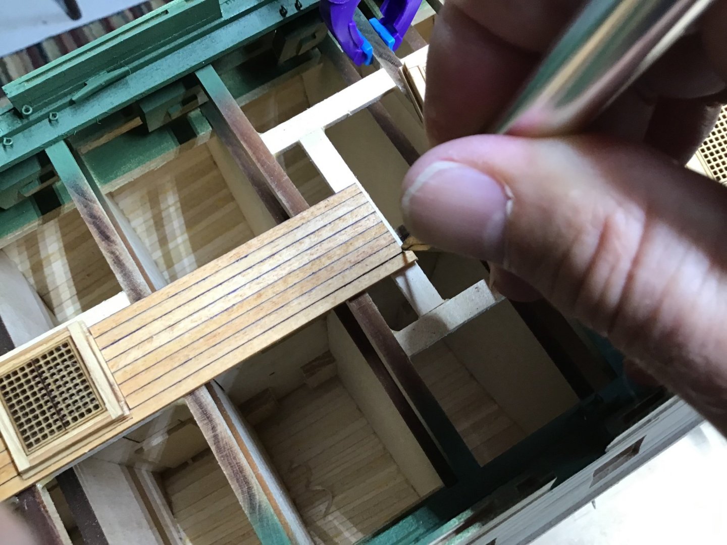
Last is to cut the overlapping forward and aft ends to fit, make a mark with an X-Acto and cut to the mark on the table saw. Picture 6.
Picture 7 shows the final result.


- GrandpaPhil and Duanelaker
-
2


USS Constitution by ERS Rich - Model Shipways
in - Kit build logs for subjects built from 1751 - 1800
Posted
Thanks Boats, one motivation for doing the log is a record to refer to when I don’t remember how I did it the next time around….
About the trailboards, the College of Model Shipbuilding Guide shows how to make relief carvings from plastic stock, I’m not ready for that. Plan to seal the boards, then airbrush paint white, then paint the black areas and the shield with a fine brush. I think to the casual observer it will look the same as the real thing….
For the white trim, plan to also airbrush paint white, then mask the white paint and paint the remainder black. The CMS guide shows how to use plastic for the trim. However, I think plastic on wood is kind of out of character, plus there isn’t, in my opinion, such a difference between applied trim time and paint, that justifies the extra time.
Happy Labor Day!