


DocBlake
-
Posts
1,811 -
Joined
-
Last visited
Content Type
Profiles
Forums
Gallery
Events
Posts posted by DocBlake
-
-
-
-
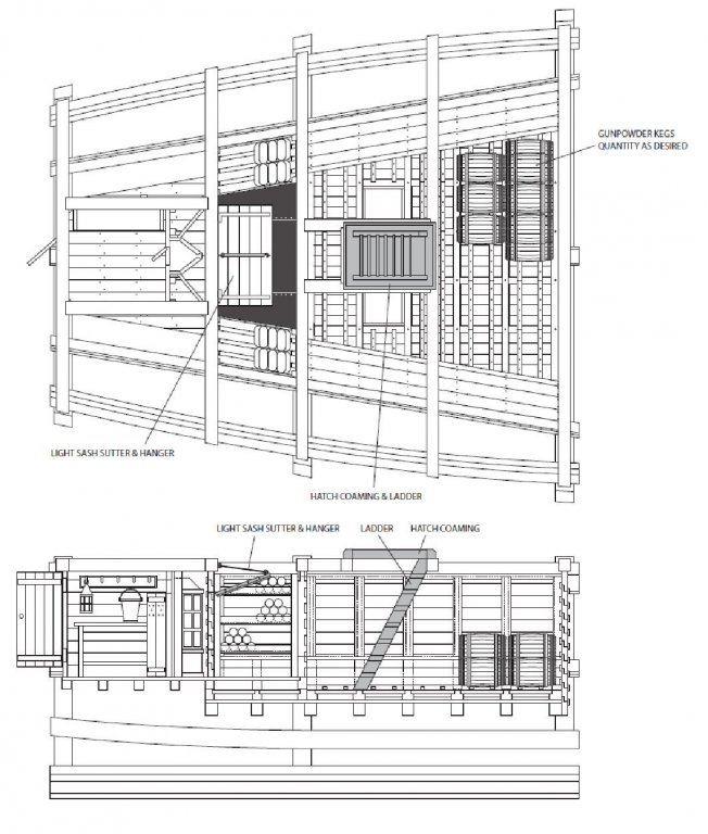
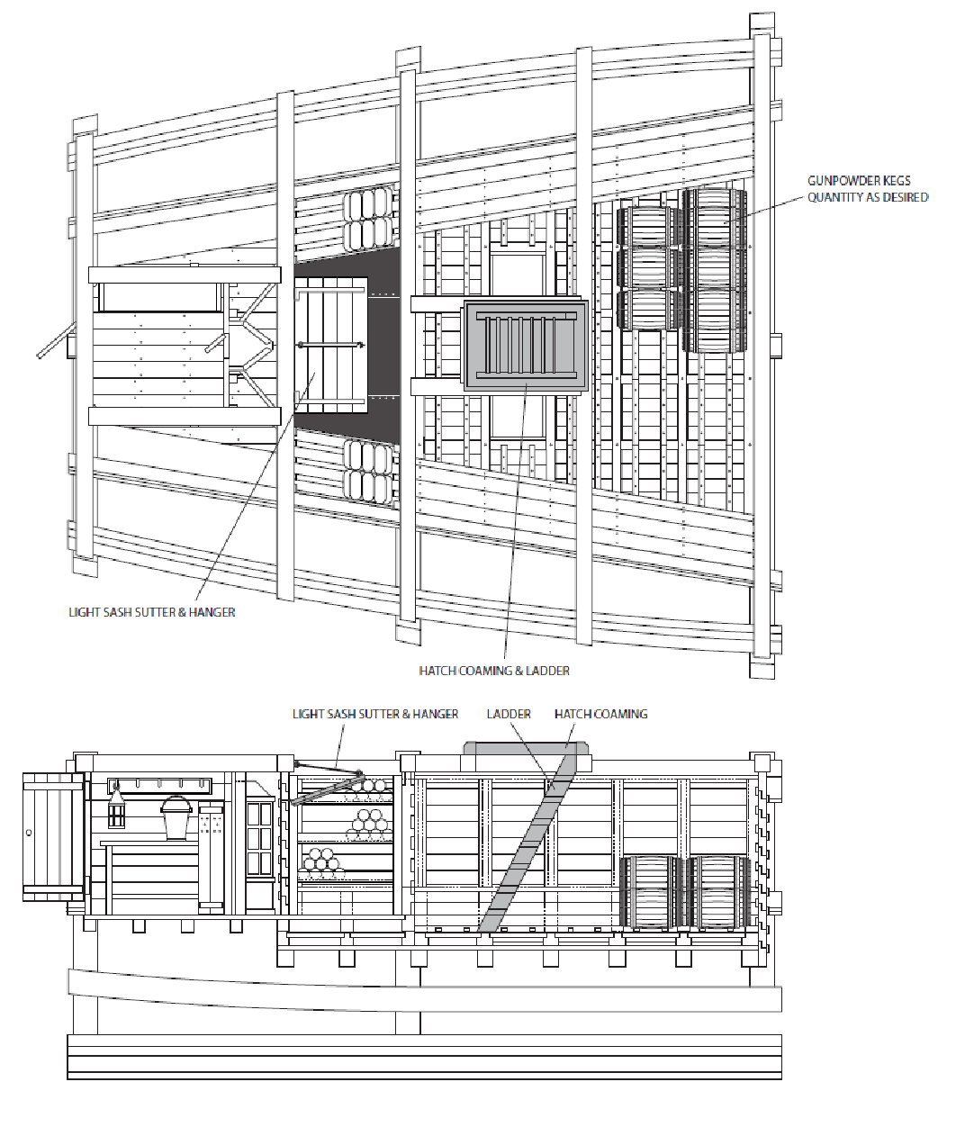
This will be a build log for my next project, a 1:32 scale model of an aft magazine including a light room, filling room and powder room. I will use a variety of hardwoods for the project, avoiding paints and stains.
The plans are, once again, drawn by Jeff Staudt.
As Jeff states in his practicum:
"No specific ship, rather a concept showing the various components that make up the magazine, and how it's fitted into the vessel.
She's built using a different approach. Rather than make the hull framing first and build the magazine in place, it will be added last and act as the display "cradle" for the finished model. ""HISTORICAL BACKGROUND OF THE SHIP MAGAZINE
18th century shipwrights were faced with two major issues when designing the magazine for ships; Keeping the gunpowder and contents stored there dry, and that of safety from the danger of any open flames of candle light or being hit from shot by enemy fire during battle. Thus they were typically fitted low in the hull below the waterline.
The magazine consists of three distinct compartments. Generally speaking, they are the:
Powder Room – This large area was used to store the kegs of gunpowder. Depending on the size of the ship a large amount of highly explosive content would be kept here.
Filling Room – This room adjoined the powder room and was used to fill, store, and distribute the powder cartridges for the ships guns.
Light Room – The means to illuminate the powder and filling rooms. This area was completely isolated from the other two, with a separate scuttle, or passageway to access it.
As the build progresses I'll get into more detail of the construction of each area.
ORIENTATION OF THE MODEL
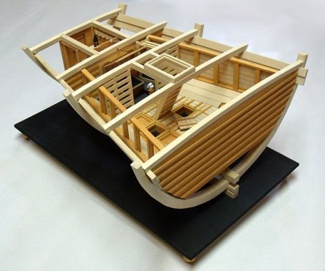
The magazine will be located in the Aft portion of the ship with the light room farthest to the rear, progressing forward to the powder room. The finished model will be displayed looking inboard from the starboard side. "Here's a look at part of the plans and a photo of Jeff's prototype:
- KenW, DORIS, Ryland Craze and 10 others
-
 13
13
-
-
I own a Byrnes saw and I wouldn't trade it for the world! A marvelously precise and well designed tool. My go-to for all cross cutting, ripping , mortising etc. The only flaw in the saw is the lack of a tilting arbor for angle cuts. The tilt table accessory is cumbersome and time consuming to set up, and not really amenable to small pieces of stock. I'm thinking of investing in a dedicated tilting arbor saw for angle cutting. Recommendations??? Proxxon vs. Micro Mart?? Which model (s)?? Where to purchase - Ebay vs website?
-
-
The fashion pieces on Hannah are a little odd, both in shape and in placement.
- jct, popeye the sailor and thibaultron
-
3
-
Great job, Bob! All the best to you and those you hold dear this Holiday Season!
-
Glad to hear all went well. Welcome back!
-
Really innovative, David. The hoops (and the pump) turned out great!
-
I’ll be following this build. I’ve always been interested in Hannah and would like to do a POF build at a larger scale. This build is intriguing, though.
- mtaylor, jct, thibaultron and 1 other
-
4
-
Hi David!
I was unaware of this build, but now I’m here. Great job! I’ll be following with interest. I spent a couple of hours on the Morgan at Mystic two years ago.
-
-
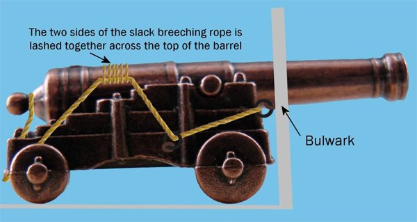
For those of us who hate to rig cannons, here's a great idea. I've not yet seen this method of securing a cannon when not in use. The train tackles are attached to the carriage and bulwark by hooks, so they can be removed. The breeching line is then lashed across the top of the cannon barrel. Slick!
-
Great job on the rigging, Bob!
- Canute, Old Collingwood, Osmosis and 1 other
-
4
-
-
-
I assume in most cases the keelson was bolted to the frames with metal bolts. What would be the spacing? one per frame? Two per frame?
- mtaylor and pontiachedmark
-
2
-
-
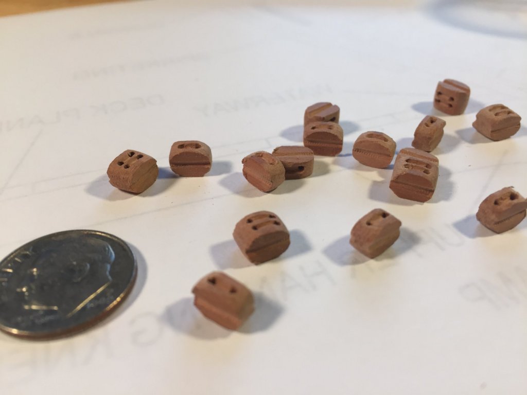
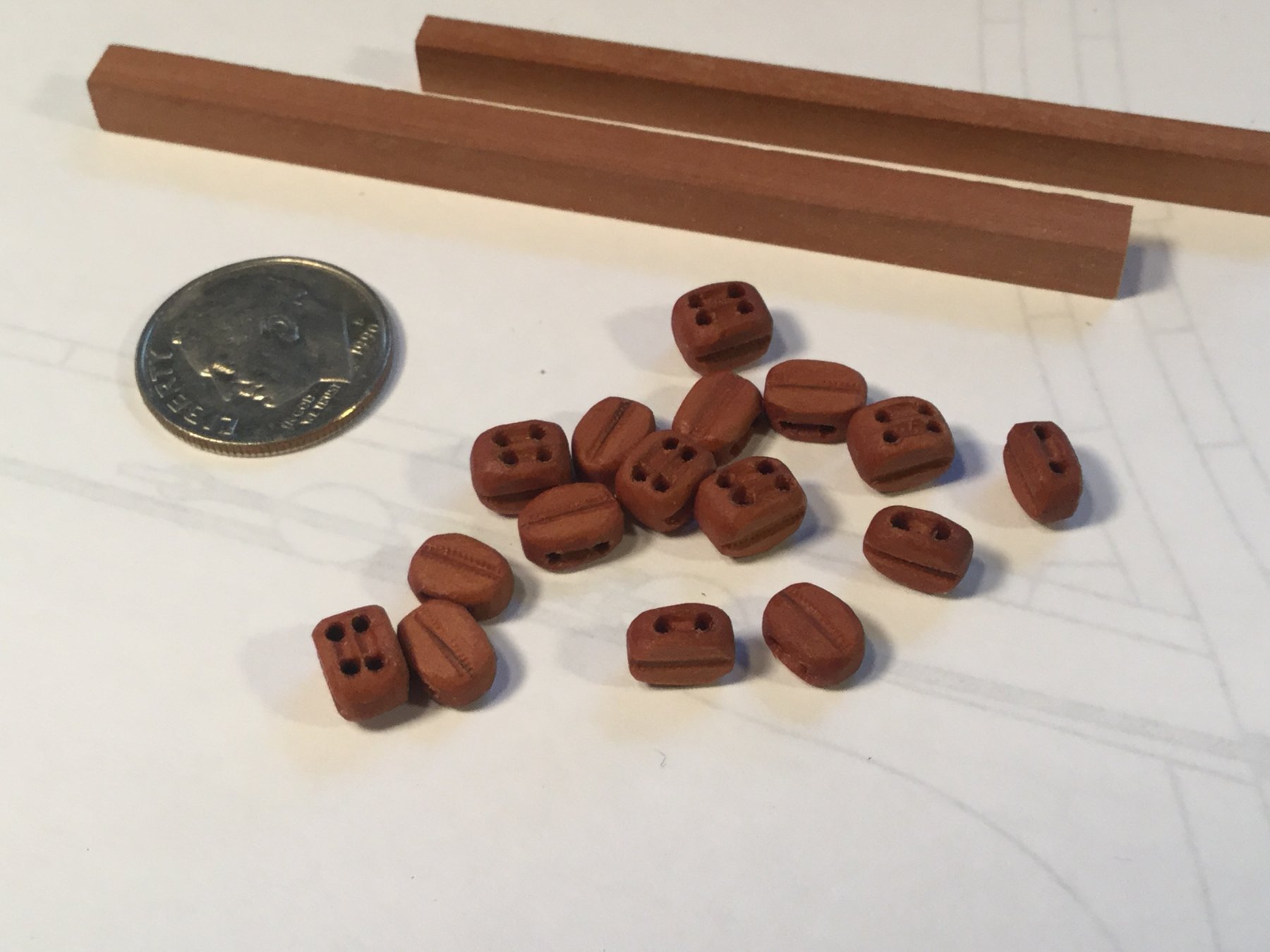
A lot of things have gotten in the way, including a 17 day holiday, but I'm back in the shipyard. The next thing up on the battle station build is the blocks. Trying to stick to the totally scratch built principle, I made them from scratch. The blocks for the cannons would be 8" long, or 1/4" long in scale. I milled up some 3/16" square stock for the double blocks and 1/8" X 3/16" stock for the single blocks. I need 6 double blocks and 10 single blocks. The extra single blocks are for rigging the gun port lid control lines. The stock is swiss pear.
I marked and drilled the sheave holes with a #60 drill, then used a curved X-acto blade to cut out the simulated sheaves. The blocks were sanded round on the stock, then cut off and the other side sanded round. The stropping grooves were marked with an X-Acto and shaped with a file. All that is left is a final sanding and a bath in some boiled linseed oil to darken and protect them.
-
-
I’m with Brian. Great job on the treenails!
-
The veneer isn’t going to need radical sanding, so I’d start with 150 grit in a rubber backed sanding block. 200 grit final is all you’ll really need.
- CaptainSteve, lmagna and BETAQDAVE
-
3
-


Aft Magazine Section by DocBlake - 1:32 Scale
in - Build logs for subjects built 1751 - 1800
Posted · Edited by DocBlake
Thanks, Michael!
Construction begins with a base deck which supports the magazine. I chose cherry for the beams supporting this deck. There are eight beams altogether, and there is framing beween two of them to create two scuttles, which allow access to the bilge for repairs or to clear debris. Laying out and planking this deck needs to be precise, so the plans provide for a jig to hold each deck beam perpendicular to the center line and a fixed distance from each other. The final photo shows the beams resting in place. The beam ends are beveled 11 degrees in the horizontal plane and 45 degrees in the vertical plane (not yet done in this photo). The scuttles have also been framed in.