


DocBlake
-
Posts
1,811 -
Joined
-
Last visited
Content Type
Profiles
Forums
Gallery
Events
Posts posted by DocBlake
-
-
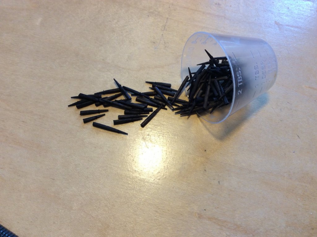
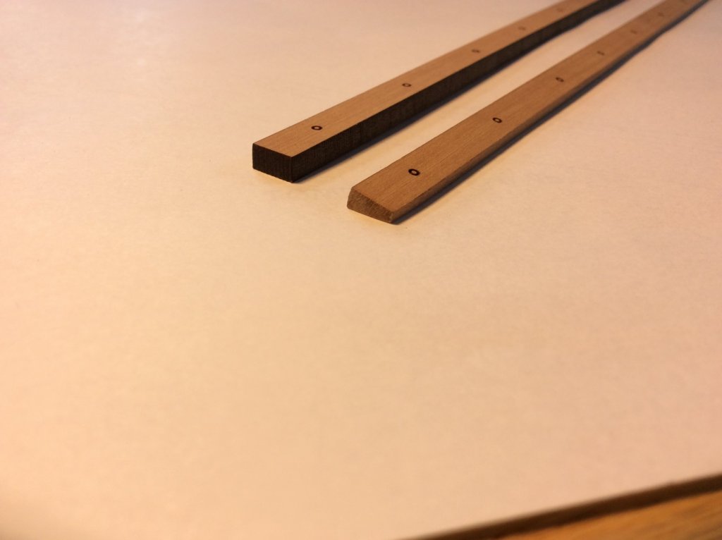
I use black annealed wire to simulate smaller bolts - a 3 pounder cannon carriage in 1:48 scale. At this scale the bolt head would be 2 scale inches in diameter (1/16"). It would be hard to fine the proper wire, and very tough to sand it down. The toothpicks work easily!
-
Thanks for stopping by, Richard!
I use black Fiebing's Leather Dye. Cut off the ends of a bunch of toothpicks and let them swim in a bath of the dye overnight. The birch sucks up the dye, so when you cut off the little bolt level with the plank there is no white wood in the core! Drill the appropriate holes for the bolts, touch the end of the dyed toothpick in some CA glue and push it in the hole. Cut off flush and sand. Simple.
The only thing to watch is that if your hole isn't deep enough (due to plank thickness, etc.) you may need to cut some of the tip of the toothpick piece so that there is a nice tight fit in the hole.
- Ryland Craze, Bob Legge, CDW and 8 others
-
 11
11
-
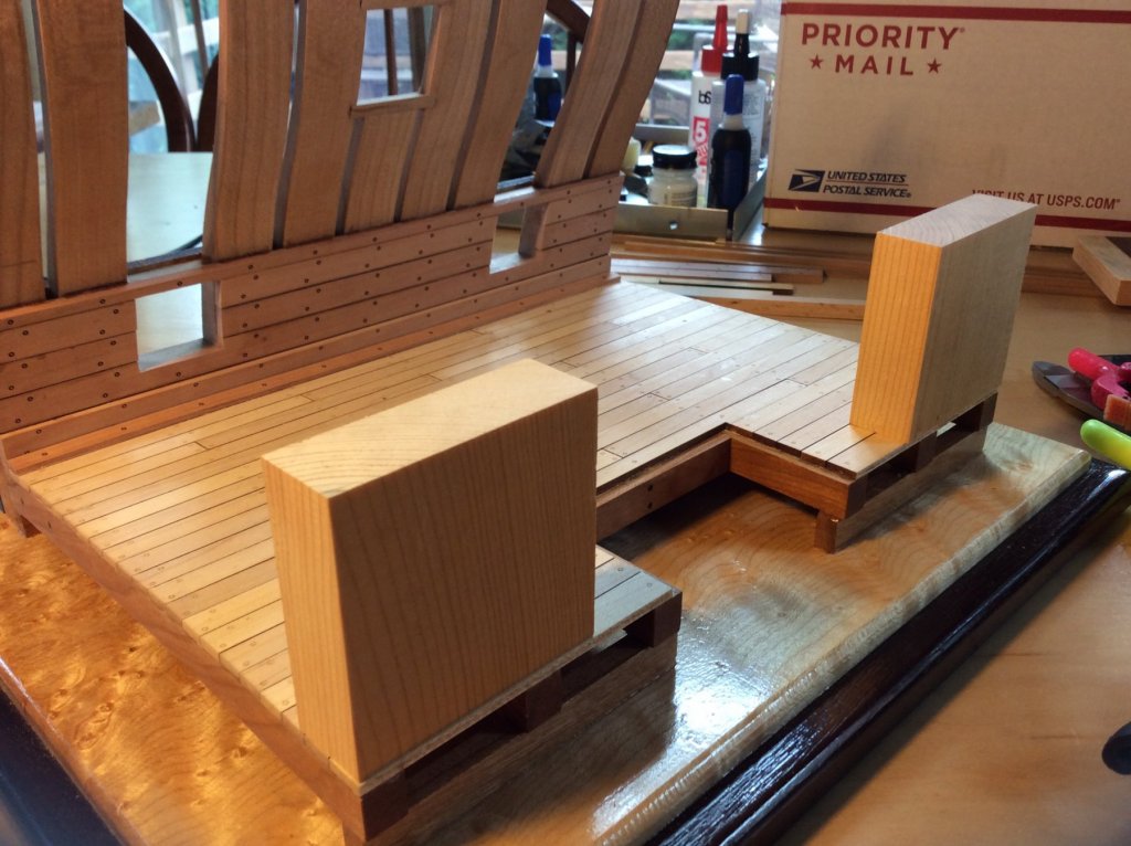
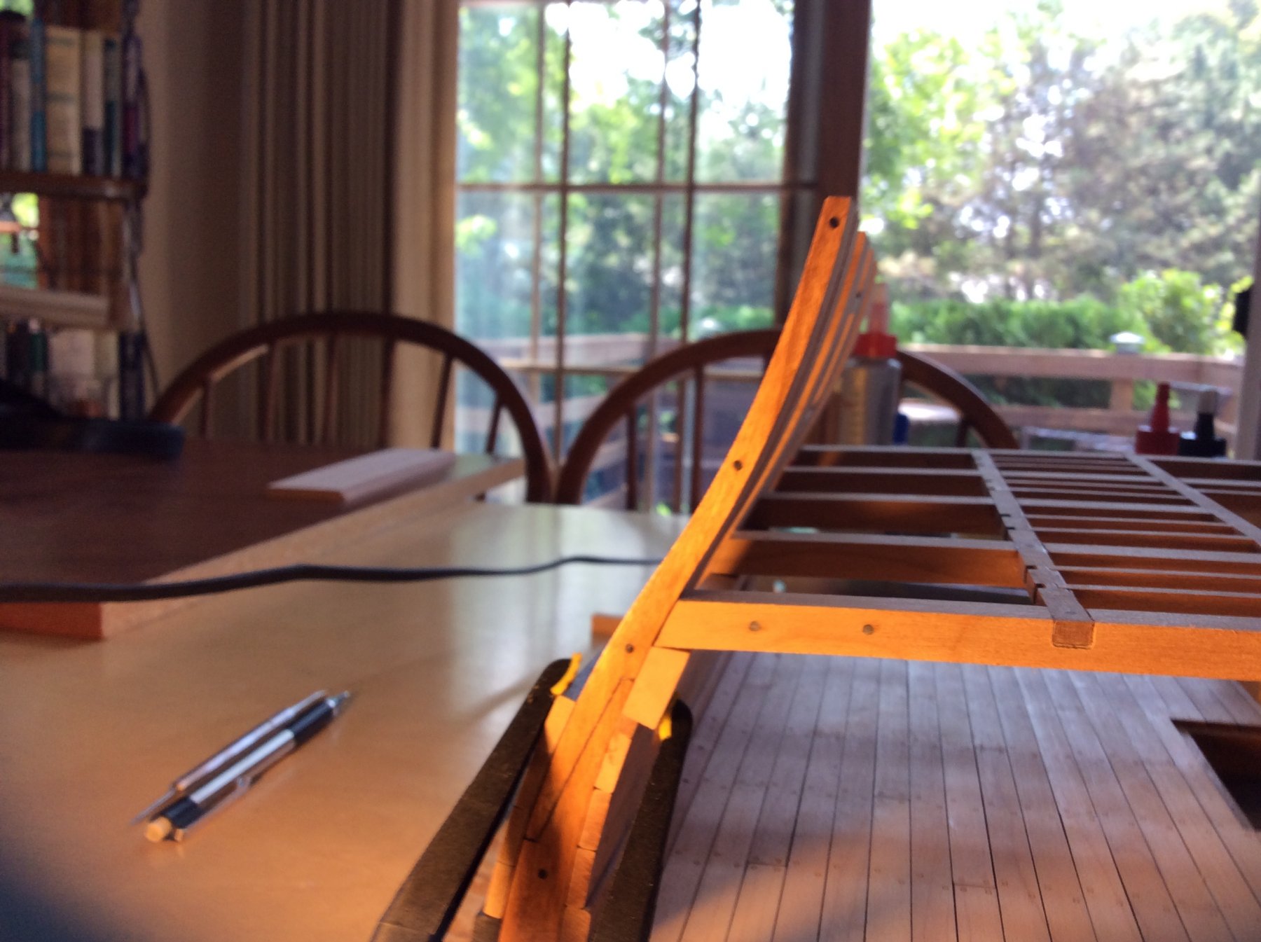
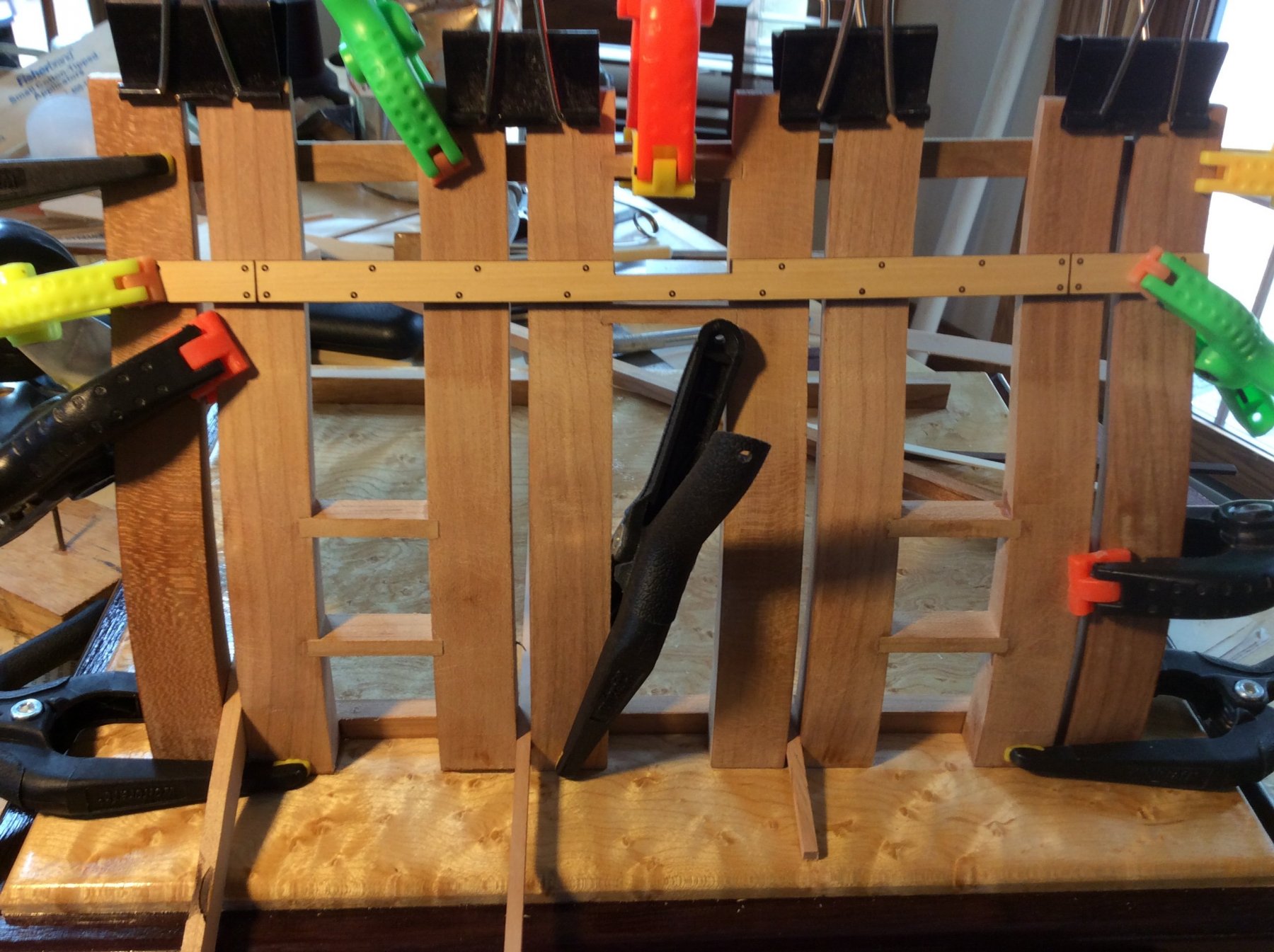
I started work on the upper deck clamp. The the lower edge of the clamp was fine, sitting squarely on the spirketing. The lower edge of the deck beams must be 2-1/4" above the lower deck surface. This is important so that the upper bulwark planking turns out correctly. The first thing I did was cut two blocks out of scrap, exactly 2-1/4" tall. These would be double sided taped to the lower deck and support the inboard end of the deck beams at that proper height. When I started to fit the upper deck clamp, and I ran into a problem. I thought I'd have to cut a little of the top of the clamp at an angle to accommodate the beams, and reach the "magic number" of 2-1/4". In my case, the beam sat on the clamp right at that number but there was no excess to cut on an angle to accommodate the beam resting on it. I needed a wider (taller) deck clamp. This happened because I may have been a little zealous sanding the inboard planking edges! I determined that 17 degrees was the proper angle for my model, and cut an oversized deck clamp. I then cut it the the right height by "sneaking up" on the final measurement using my Byrnes saw and carbide blade. The "magic number" is now there, but the clamp is about 3/32" taller than it should be. Hopefully no one will notice! Also, the angle the clamp is cut to would probably be better at 18 degrees, but I'm just leaving it as is! Check the photos! I also drilled holes and placed the simulated bolts that held the clamp in place.


-
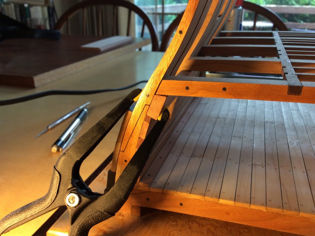
I glued the main deck beams and carlings together in my new steel squaring jig. Because the ledges were cut to size to fit the mortises in the carlings perfectly, sanding the char from the pieces made the fit too lax. i just cut some cherry stock, milled it to the proper thickness, and cut my own ledges that I custom fit to the deck and glued them all in place. The lodging knees, hanging knees and the remainder of the ledges outboard will be fitted later. Next up: Shaping and fitting the upper deck clamp
.thumb.JPG.b25ea1e237fd3edb9cd1b3514626b066.JPG)
.thumb.JPG.4d8904003986920878fc76fc6c8d2075.JPG)
- mtaylor, Ryland Craze, egkb and 14 others
-
17
-
Great work, Bob, as always!
-
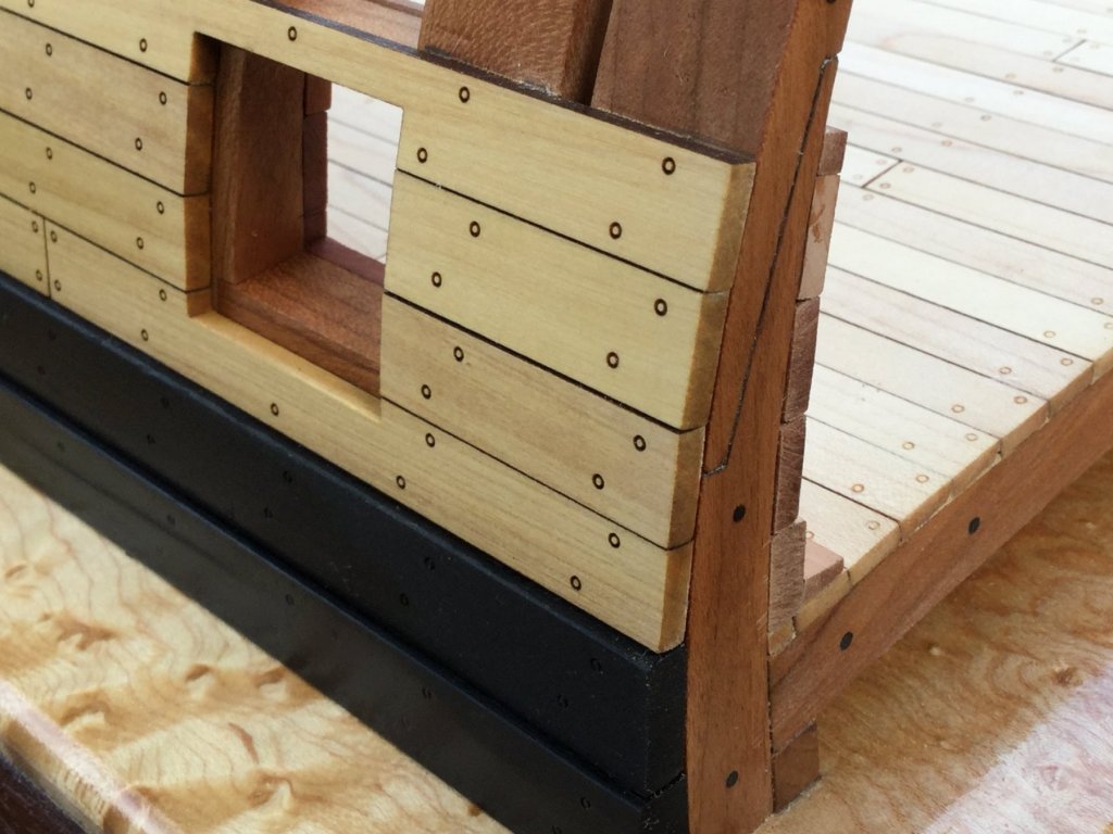
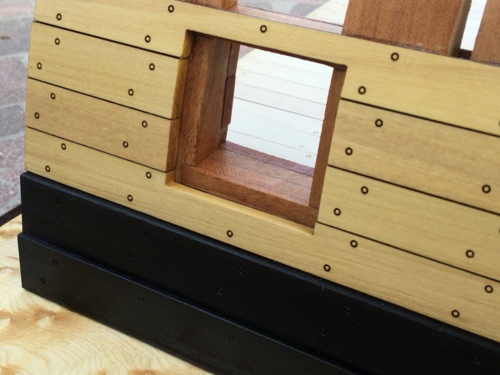
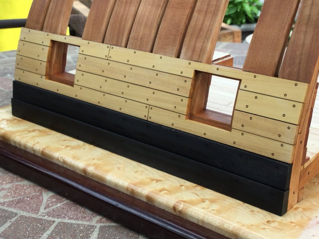
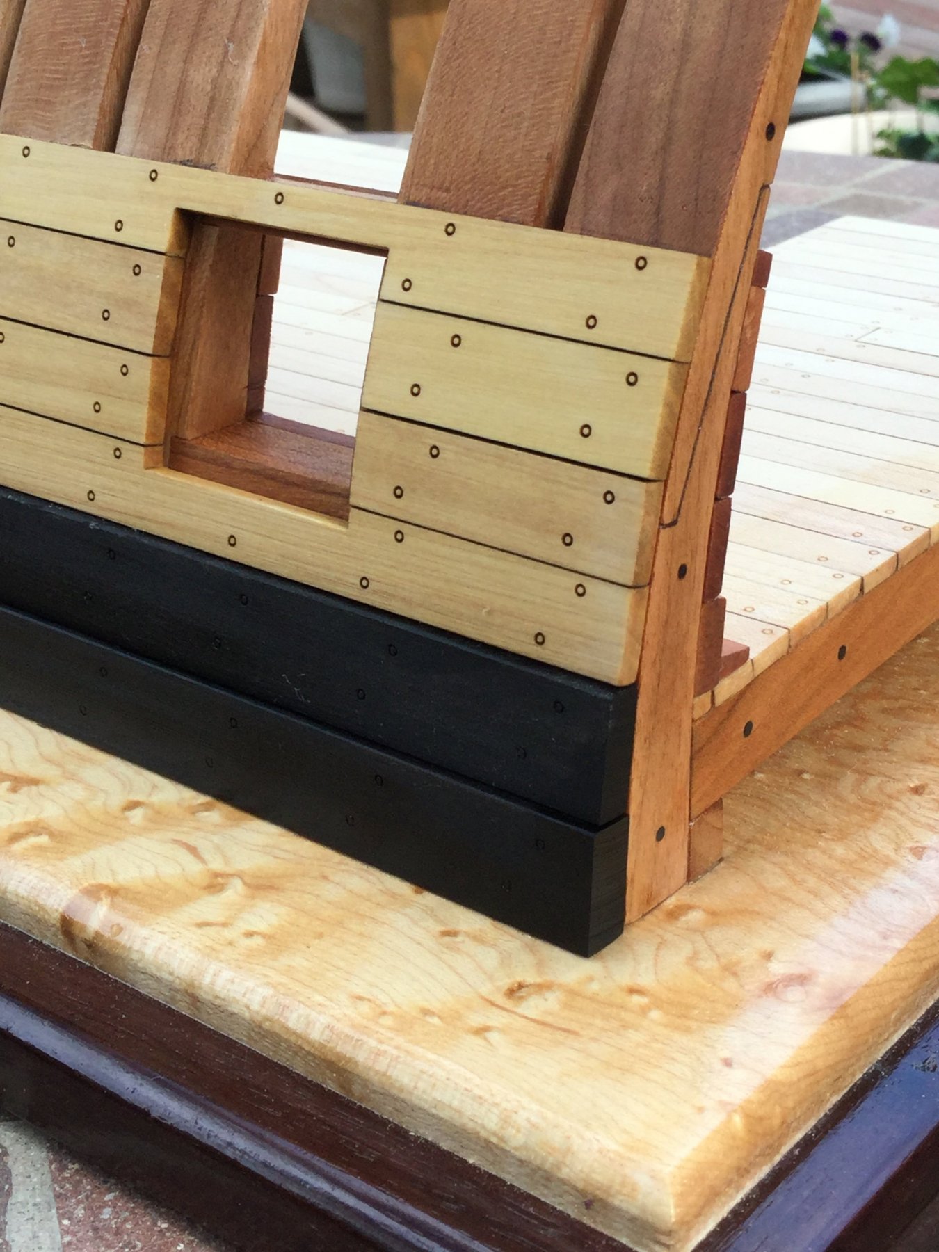
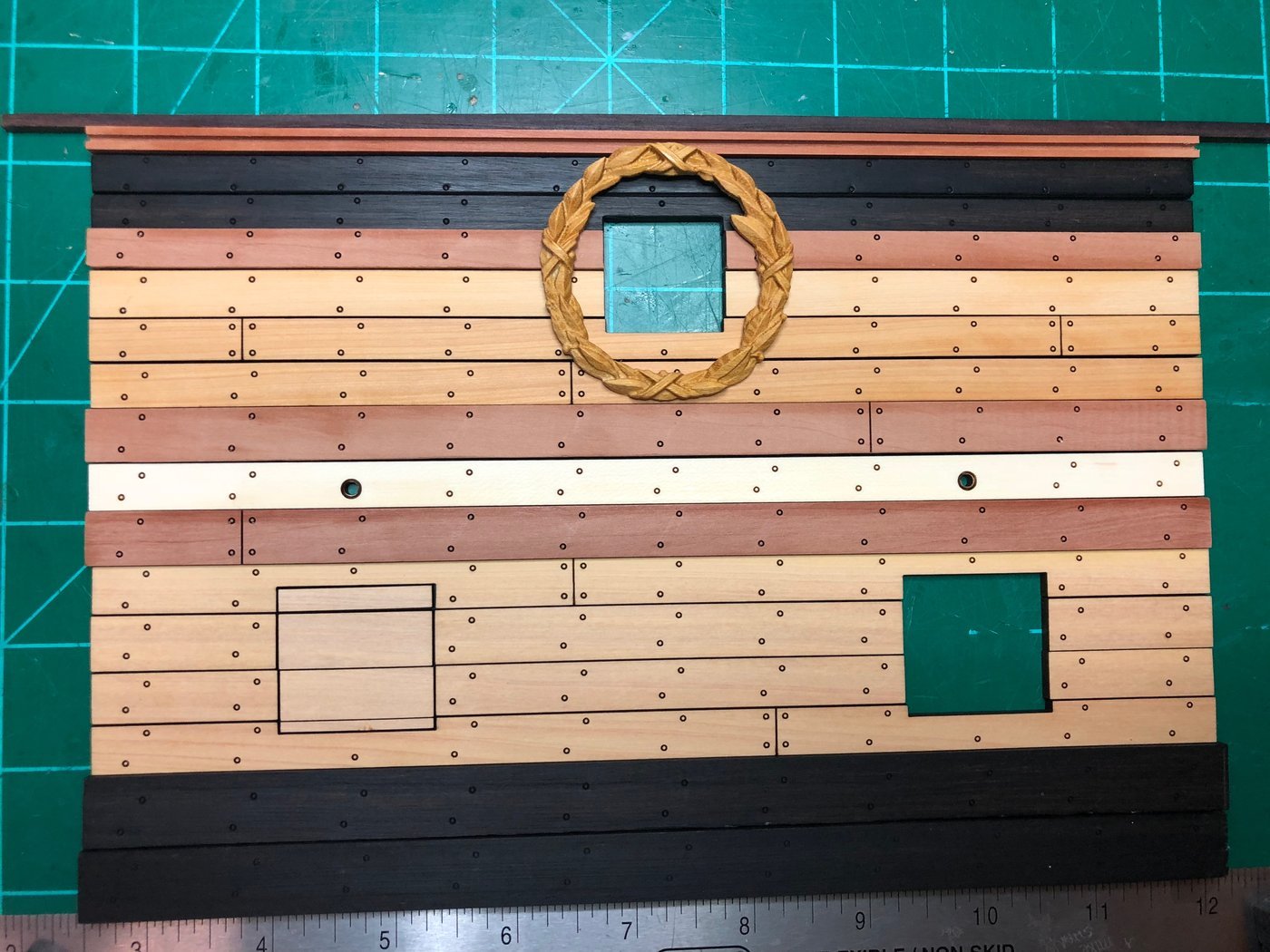
I turned my attention to the outboard planking. The model is already exceptionally rigid and once some outboard planks are added, I could probably drop it from a second story window and not damage it! The lower wale and black strake above it are ebony, measuring 1/4" and 3/16" thick respectively. The outboard planking framing the gun ports is boxwood. I included some detail shots on how the gun ports turned out and the ends of all the strakes at the exposed frames.

- oneslim, JpR62, marktiedens and 19 others
-
22
-
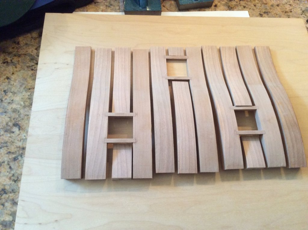
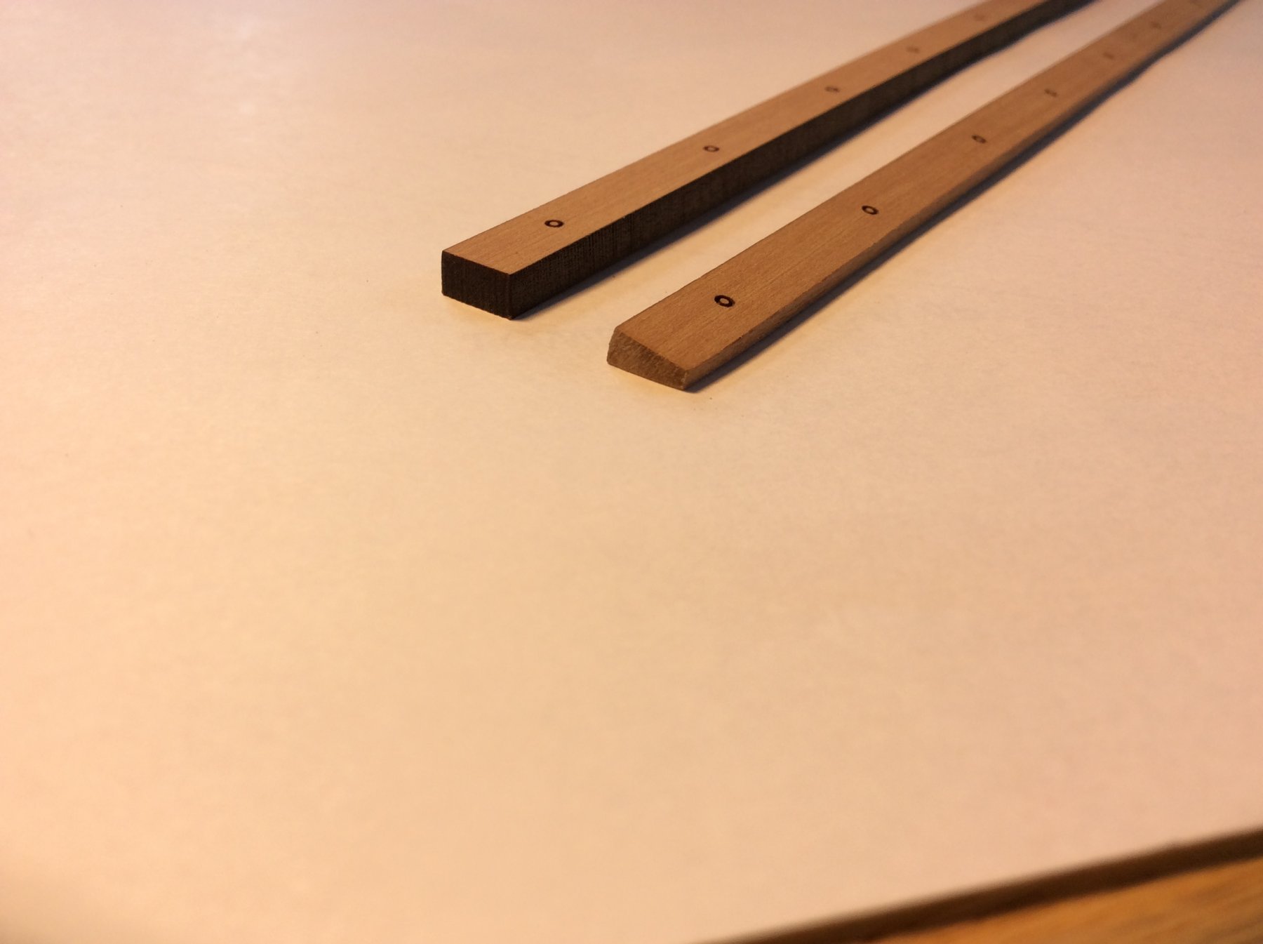
After I finished the waterway I installed the lowermost spirketing plank. It is thicker than the others and required a slight bevel to fit snugly into the angle created by the deck and the hull frames. The bulwark was planked with each plank require a bevel on both edges so that in profile they resembled parallelograms. This was because of the hull's curvature. After beveling the planks fit tight to each other and the frames. The final strake is thinner than the others and defines the lower edge of the upper deck clamp. The waterway was glued in place last. All this planking is swiss pear.


-
-
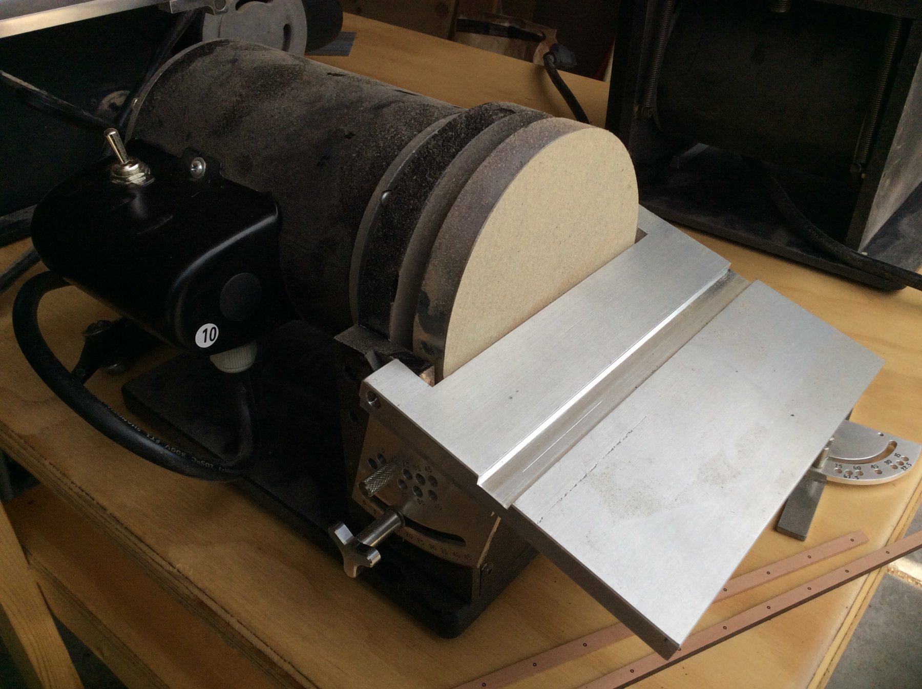
Glad you stopped by, Svein!
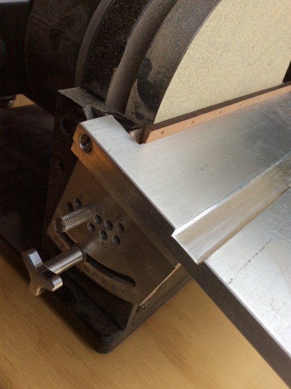
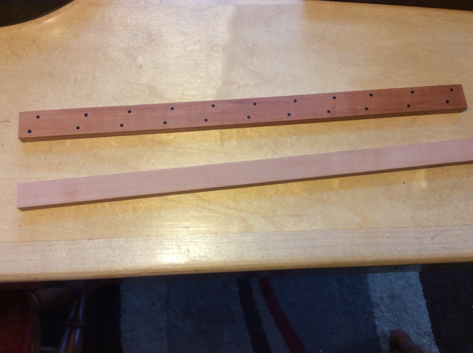
I started planking the bulwarks by forming the waterway The thick spirketing plank is actually the first plank glued in place but I wanted to get the waterway out of the way. It needs to be tapered 15 degrees across is back wide dimension. I set up my Byrnes sander and it made fast work of the job. The last photo shows the rough blank for the upper deck waterway and the finished lower deck waterway.

- Canute, Magellan1520, GrantGoodale and 7 others
-
10
-
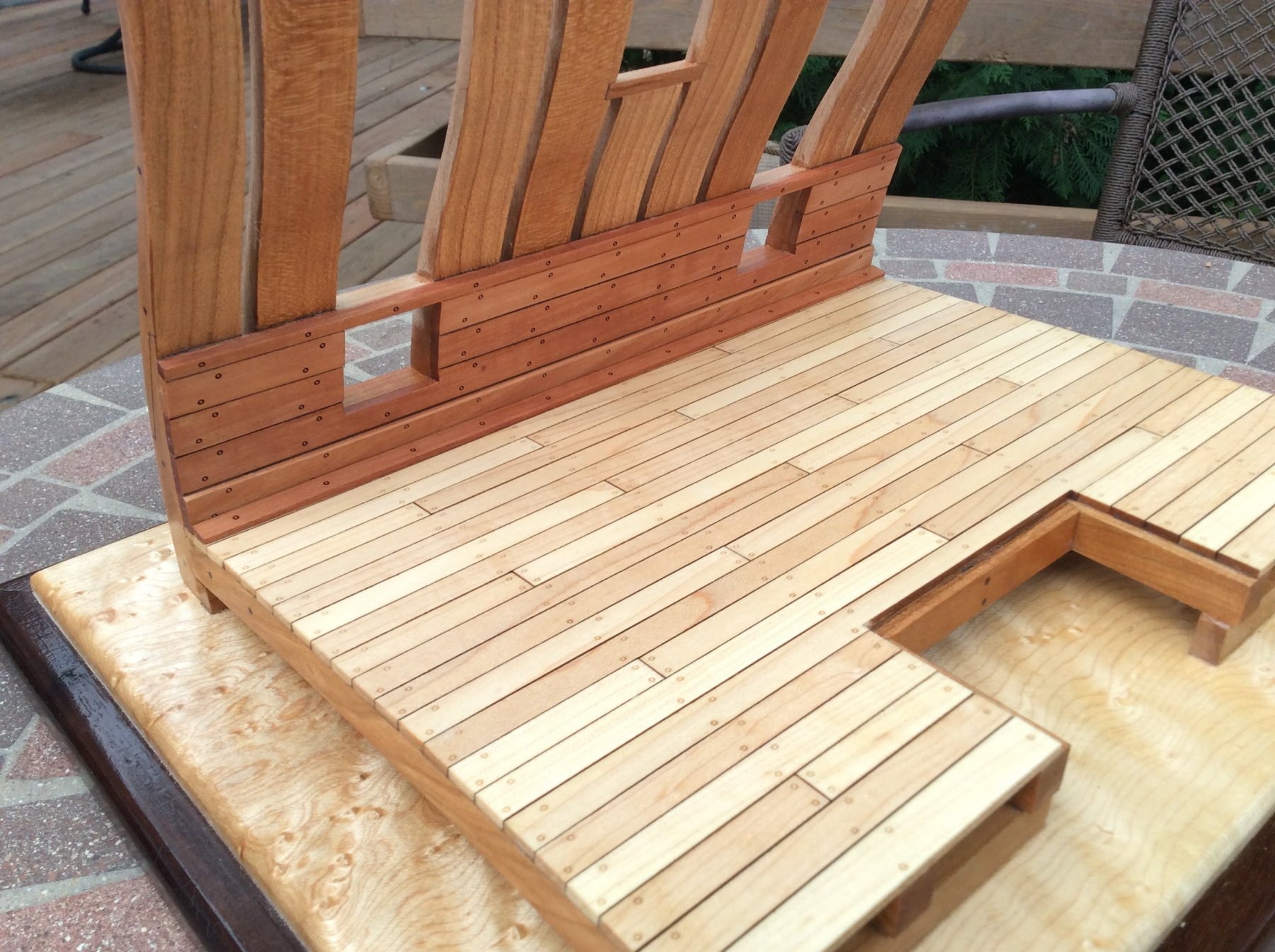
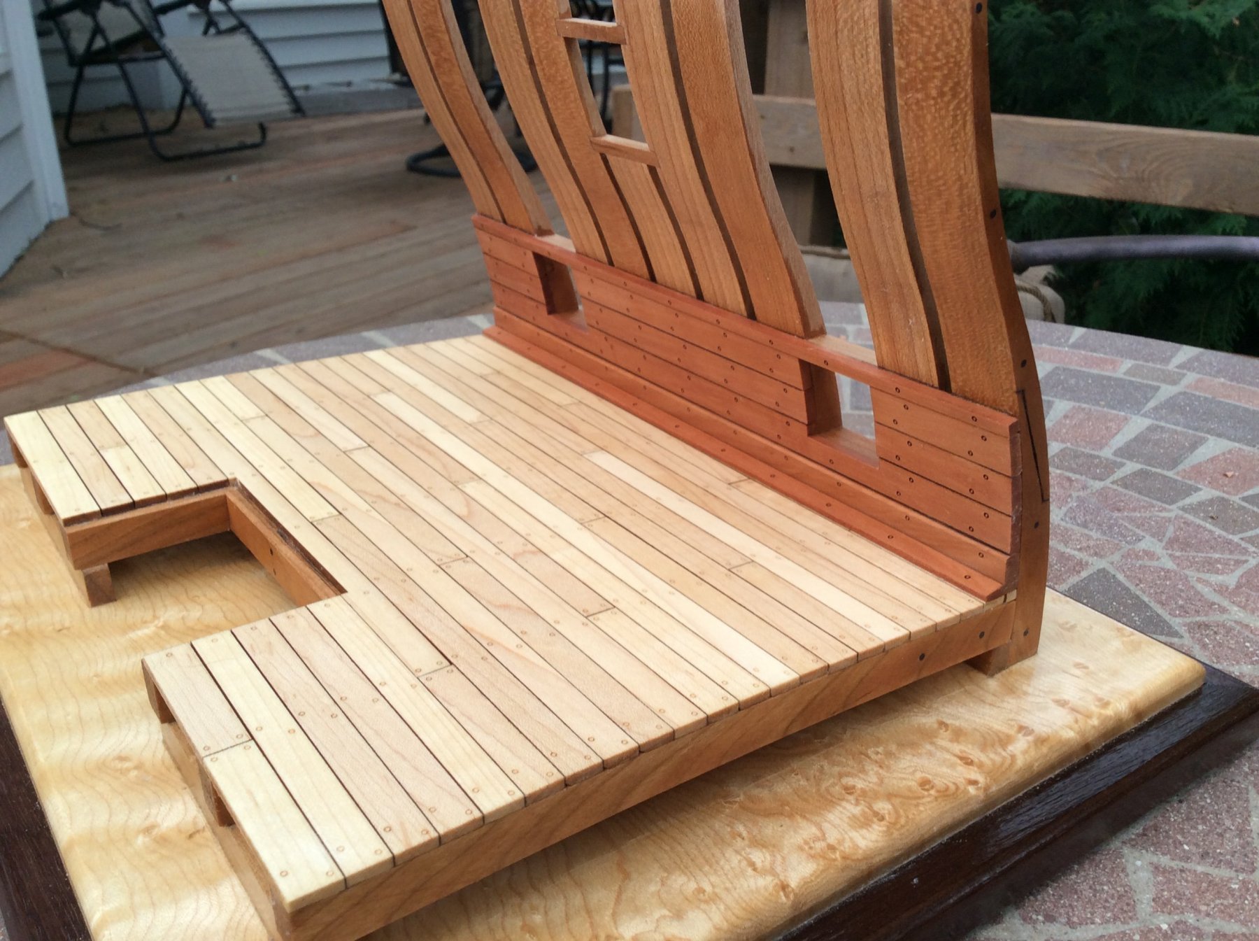
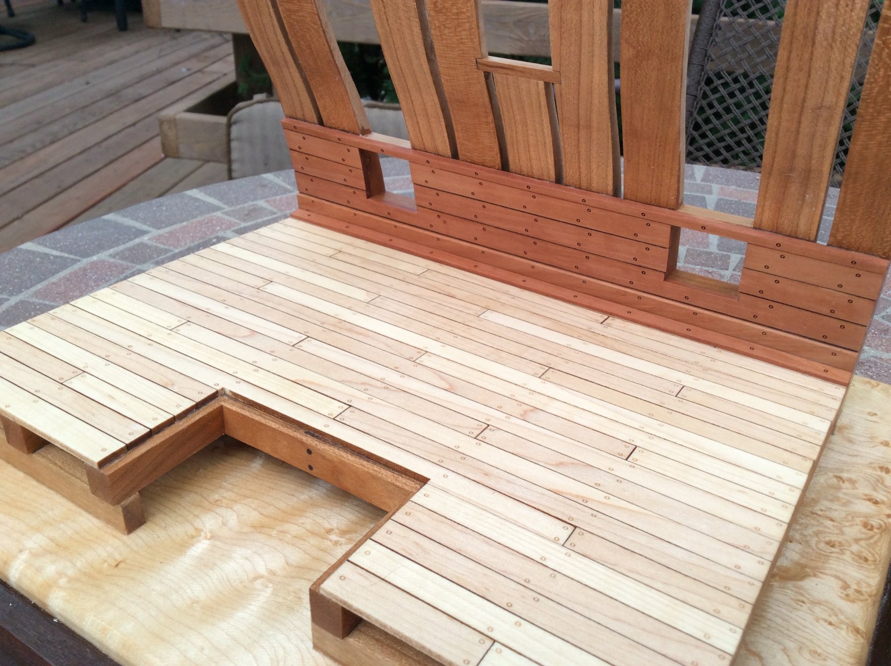
-
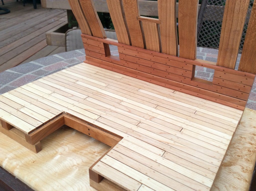
The lower deck was installed next. All the decking for the three kits was randomized so there was no discernible grain pattern in the finished deck on any of the three models. The effect is much more realistic the a plain vanilla deck of holly would be...although we did consider holly for the decking! Next is a fine finish sanding and some poly on the decking.
.thumb.jpg.d4364bc90637ac5e2e488592bdf88110.jpg)
- MEDDO, coxswain, Ryland Craze and 13 others
-
16
-
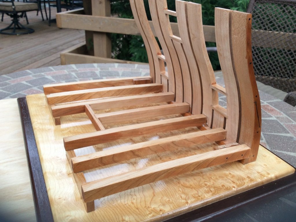
The frames are all glued in place except for the upper futtocks, above the gun ports. I'll wait until the main deck clamp is installed. Although most of the gun deck beams will be hidden by planking, the ends are plainly visible and the beams must be laid out exactly so the butt joints and treenails fall in the center of each beam. Each kit was provided with different wood options for the channel wales, great wale, gun port control strake, sheer trim etc. The fourth photo is a preview of my choices for finishing the outer hull.
- Seventynet, DORIS, cristikc and 17 others
-
20
-
-
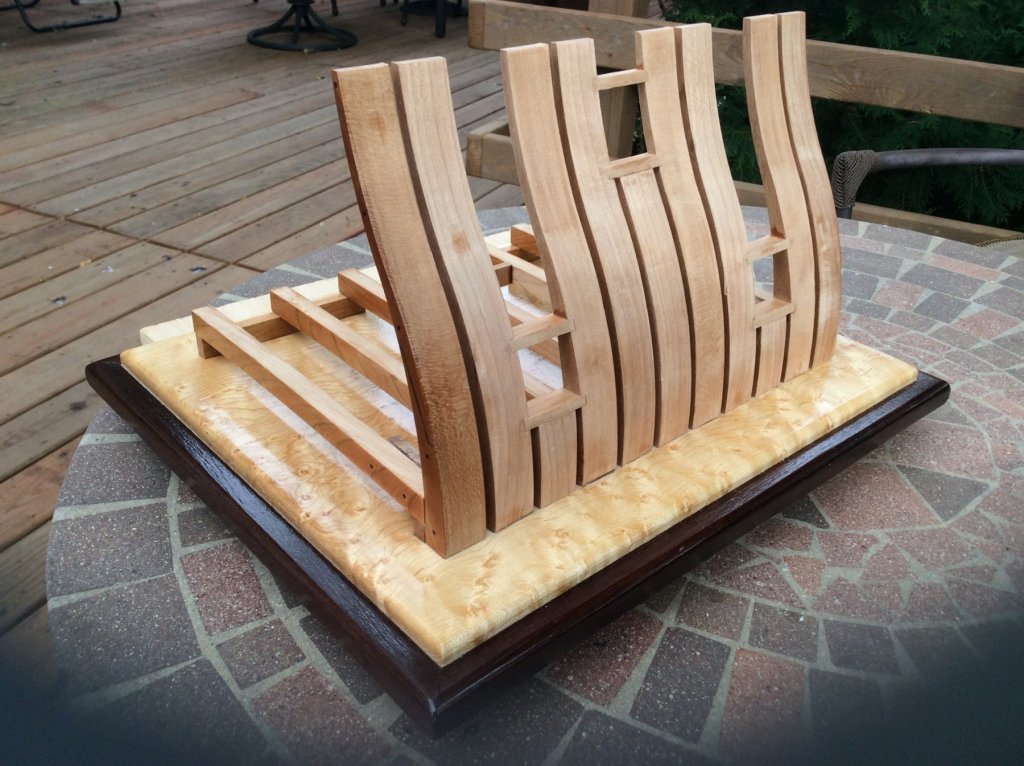
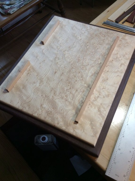
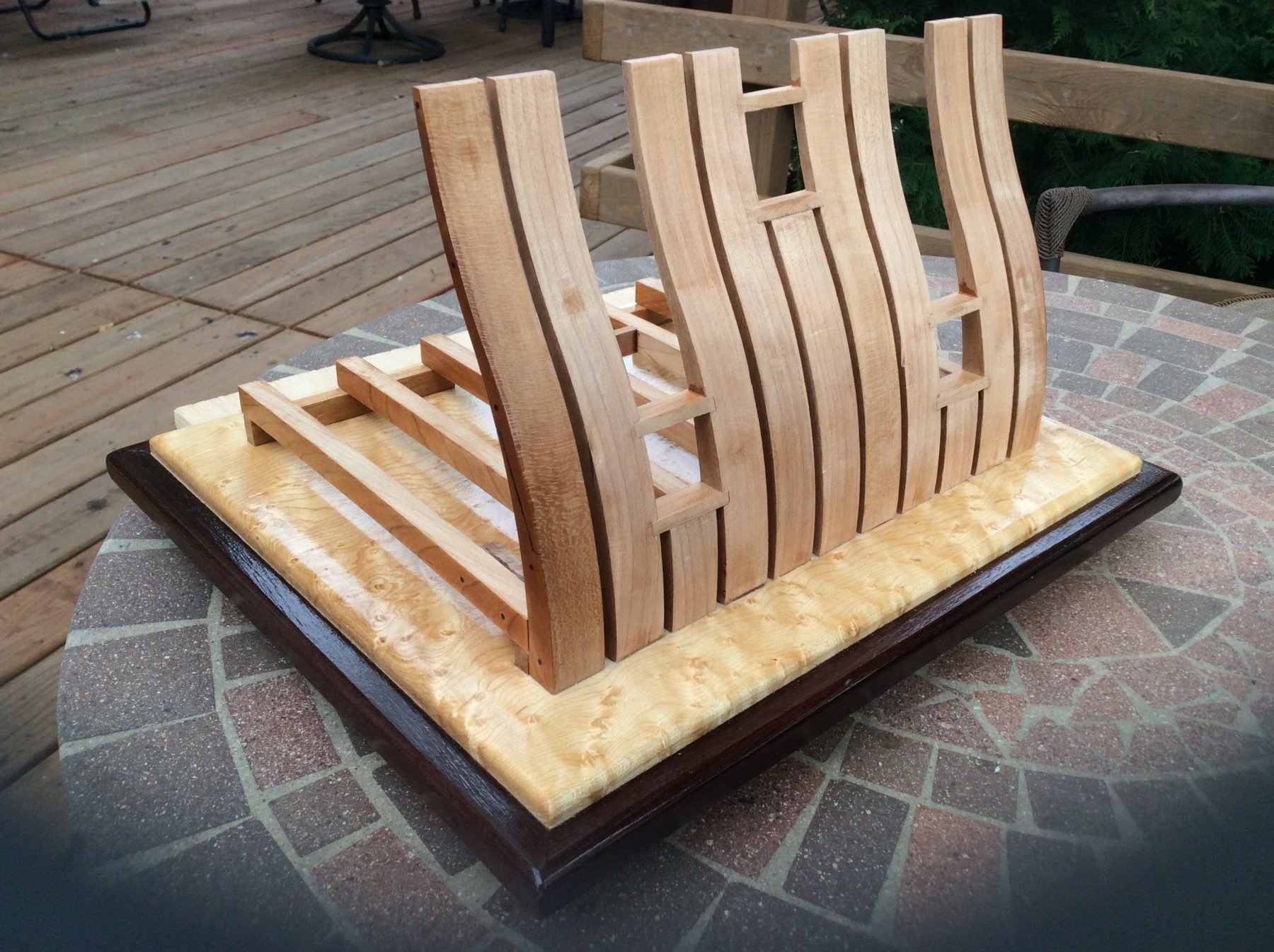
I started gluing up the frames by attaching the two outermost ones to the buildboard and the deck clamp. I built a quick little jig to ensure these were exactly perpendicular, and measured the same distance apart at the top as at the bottom. the jig straddles the deck clamp and keeps the frames square to the buildboard.
Because the planking is pre-cut and pre-treenailed, it's very important that the inside frames align with the three gun ports properly.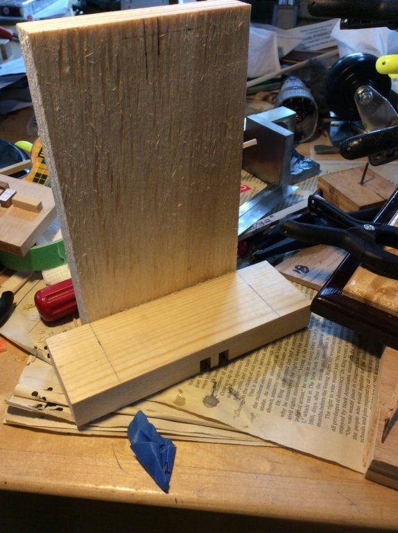

-
-
Thanks for looking in, guys!
Model Ship Builder does have this kit available. The wood is milled by Dave at the Lumberyard but the kit is sold by Winston at MSB who owns the rights. Here is a link: http://modelshipbuilder.com/page.php?131
Our kits have some features and options not available in the commercial kit. The surface etched treenails, gun port covers and individual planks for decking and bulwark planking for example. We also use some woods not included in the commercial version, including rosewood, holly and boxwood. The deck supports holding up the weather deck are actually turned on a lathe in our kit. Unfortunately, given what goes into this kit, we'd likely have to price ourselves out of the market even if we did own the rights and started making kits!
-
-
I trimmed the sills and finished sanded all the frame parts. I also glued the support piece between the two deck beams that frame in the hatch. I also test fit the deck beams on the build board. There is a final beam that will be fitted once the deck beams are glued in to this point.
-
I applied multiple coats of wipe on poly to the board. While waiting for it to dry, I went ahead and installed the sills that frame out the 3 gun ports at the bulwark. The sills are a little oversize in thickness, so they need to be sanded down for a nice tight fit in the frame mortises. Squaring up these assemblies is critical. I used two try squares to get things aligned and some weights to hold the parts until dry. Glue was Weldbond, with some CA applied to the joints later (drawn in by capillary action) for added strength. The sills are proud of the frame surface and need to be trimmed with a sharp blade and then sanded flush with the frames themselves.

- rafine, coxswain, Magellan1520 and 8 others
-
11
-
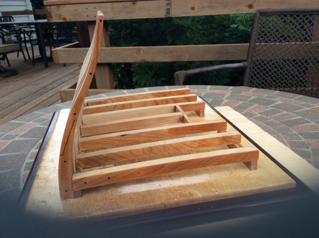
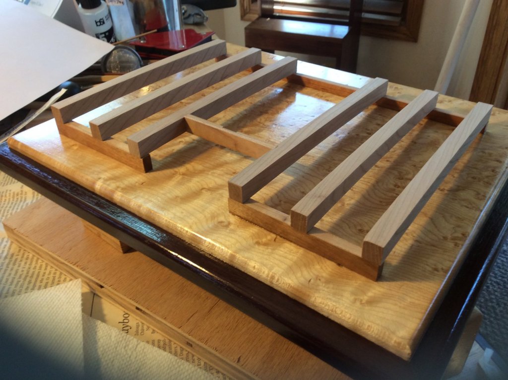
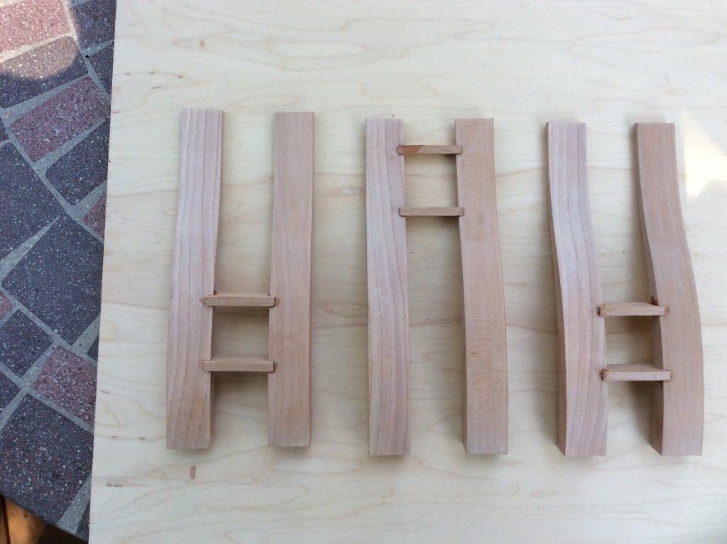
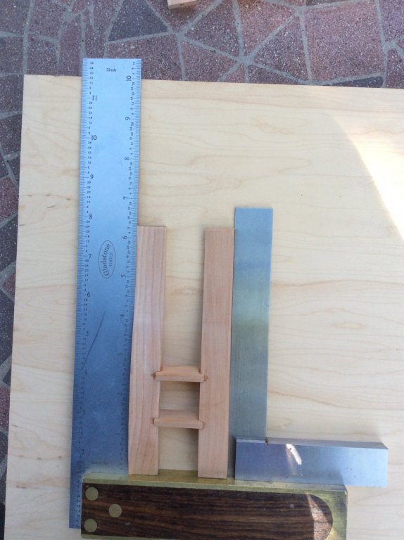
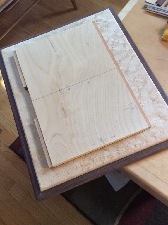
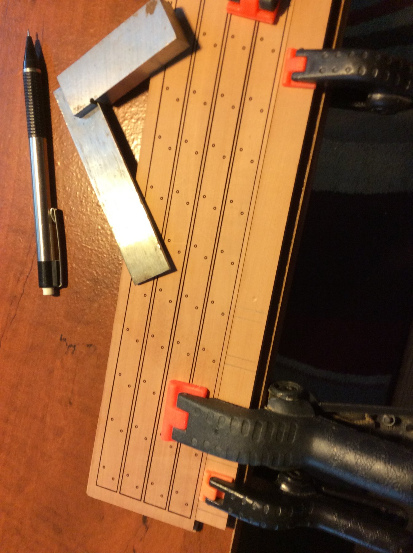
The most important part of the build is squaring up the frame from the bottom. The lower deck clamp must be parallel to the two inboard supports, and the ends of the supports must lie on the perpendicular of each end of the clamp. I drew a baseline, parallel to one edge. I then cut out a rectangle of those dimensions and used double-sided tape to stick the plywood template to the build board. The clamp was exactly as long as the template and the two supports lined up with the perpendiculars. I then glued all 3 parts in place, removing the template after the CA grabbed a bit. Before gluing the deck clamp in place the plans call for a slight bevel of the top surface to the outboard edge. One of us said it was "minuscule" and eyeballed it with his sanding block. Suffering from OCD myself, what I did was blow up the profile of the clamp on the plans, measure the actual angle (4 degrees!) and re-mill the clamp with a 4 degree bevel in the top!!! Will I ever learn??
- GuntherMT, Canute, Magellan1520 and 12 others
-
15
-
-
Nice work, Jon! At this scale, very challenging.
Sorry to hear about your back, but I feel your pain (literally). In the last 18 months I'ved had 2 MRI's, 2 EMG's, 5 epidural steroid injections and been in physical therapy twice. The neurosurgeon is talking about a laminectomy with fusion, but the chances that will solve the problem are, in my opinion, less than good. My limitations are very similar to yours. Getting old is NOT for sissies!

-
1 hour ago, allanyed said:
Dave,
Looks like a very nice piece of work!!
What is the object on top of the cannon barrel near the area of the touch hole? As this is circa late 17th century, I assume it is not a gun lock as they did not come into use until 1718 in France and soon after in England.
Again, very nice work.
Allan
Thanks guys!
Allan: The cannon barrel in the prototype is not the barrel in the kit. It was a spare we had lying around that fit the prototype’s carriages. The part was likely a gun lock.
-


.JPG.6dd91b7c6ba6ec8b7e9771113d501f85.JPG)
.JPG.14d6186f9d2d853f6be12ed35ae515f0.JPG)


.jpg.e918b7a8ab51075a30fae329939275fb.jpg)


17th Century Battle Station from HMS Mordaunt by DocBlake - FINISHED - 1:32
in - Build logs for subjects built 1501 - 1750
Posted
A little more progress!
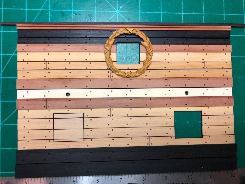
I glued the remaining half frames above the gun ports into place and worked on planking the exterior. The two channel wales and the great rail are swiss pear and the strake between them was supplied in both boxwood and holly. I chose the holly. The wale, black strake and two sheer strakes are ebony. The remainder of the outboard planking is boxwood. There will be a rosewood gunwale at the top of the bulwark. There were pre-drilled holes for the gun port lid control lines, but these had to be drilled through the framing to emerge just above the upper deck clamp's upper edge. With that done I completed the planking up to the sheer trim. The piece of trim was provided with either a double bead or triple bead design. I haven't decided which to use yet. Work turns to the upper deck next as we fit the support columns, knees and remaining ledges.
I enclosed photos made indoors with incandescent light as well as outdoors in daylight. Amazing how different the colors appear!