


DocBlake
-
Posts
1,811 -
Joined
-
Last visited
Content Type
Profiles
Forums
Gallery
Events
Posts posted by DocBlake
-
-
Yup...I need to get back to full hulls!
Chuck: how difficult would it be to modify the existing plans for Winchelsea to include the hull framing section detail as in Confederacy (post #17)?
-
Found them. Thanks, Chuck! The Winchelsea is very intriguing. I have a few odds and ends to tie up, but I am strongly considering a build!
- mtaylor, JpR62 and Ryland Craze
-
 3
3
-
Maybe I’m missing something, but why is there no forum category for the Winchelsea build logs? You can access them by typing “Winchelsea “ in the search box and the logs come up, but there isn’t a simple link on the main menu page of the forum. Am I just not seeing it?
-
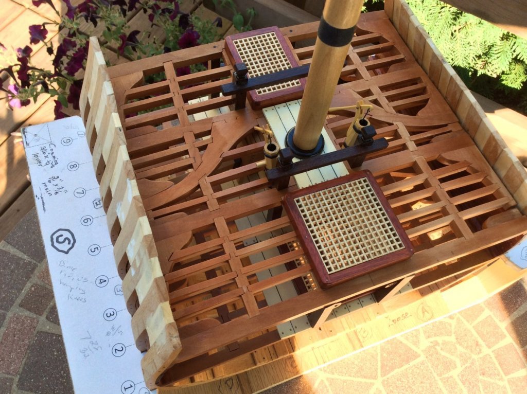
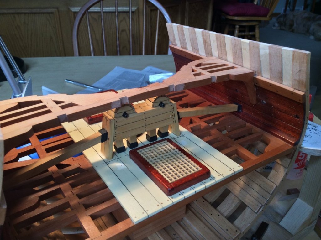
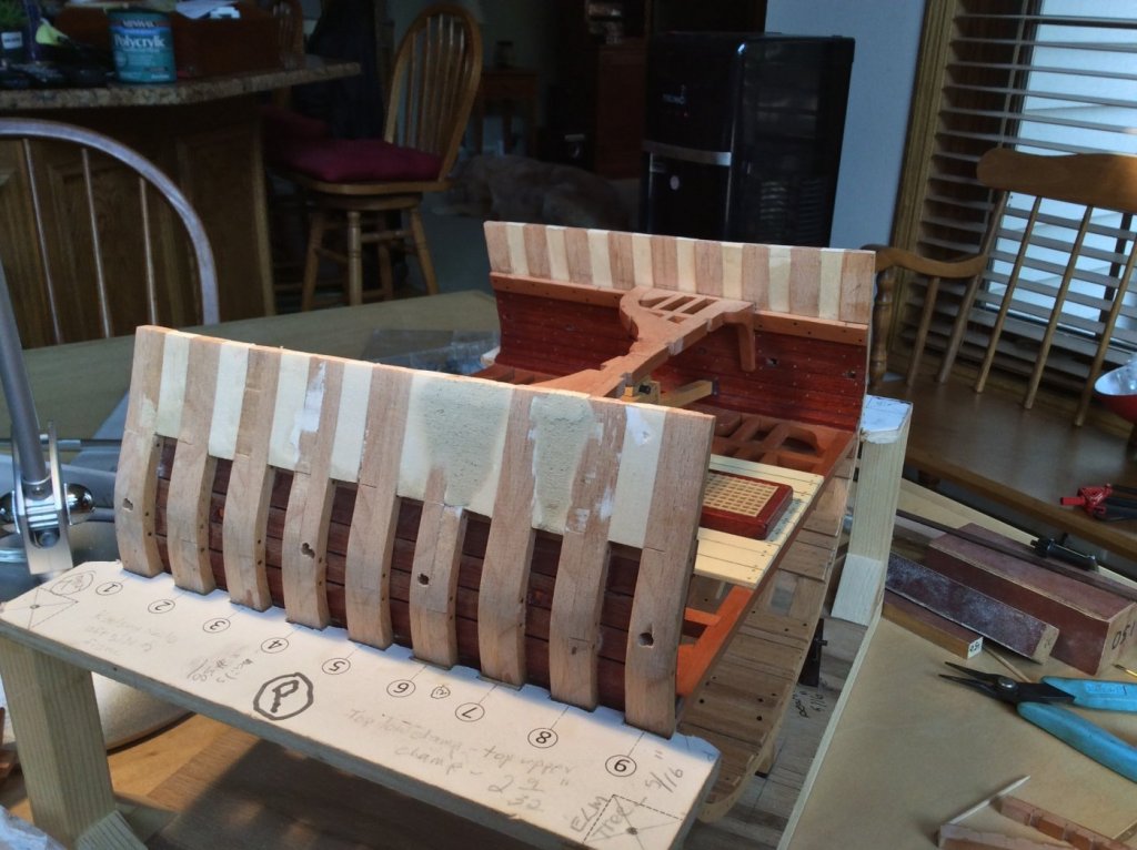
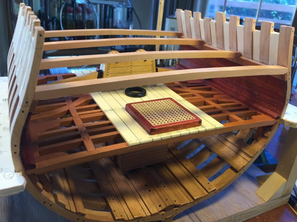
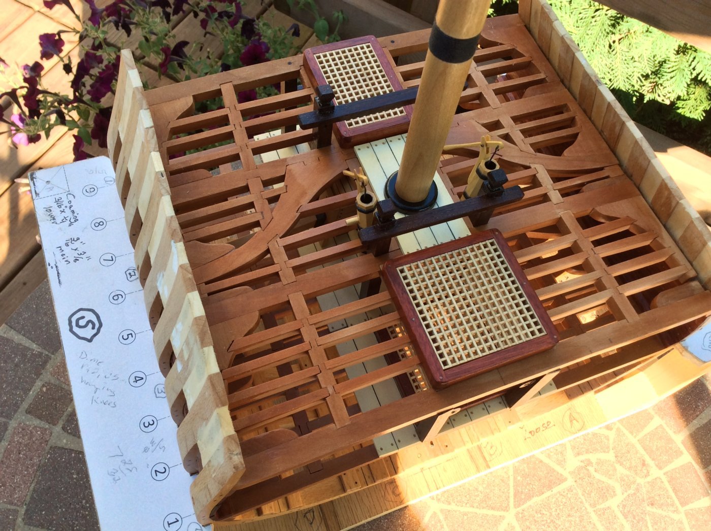
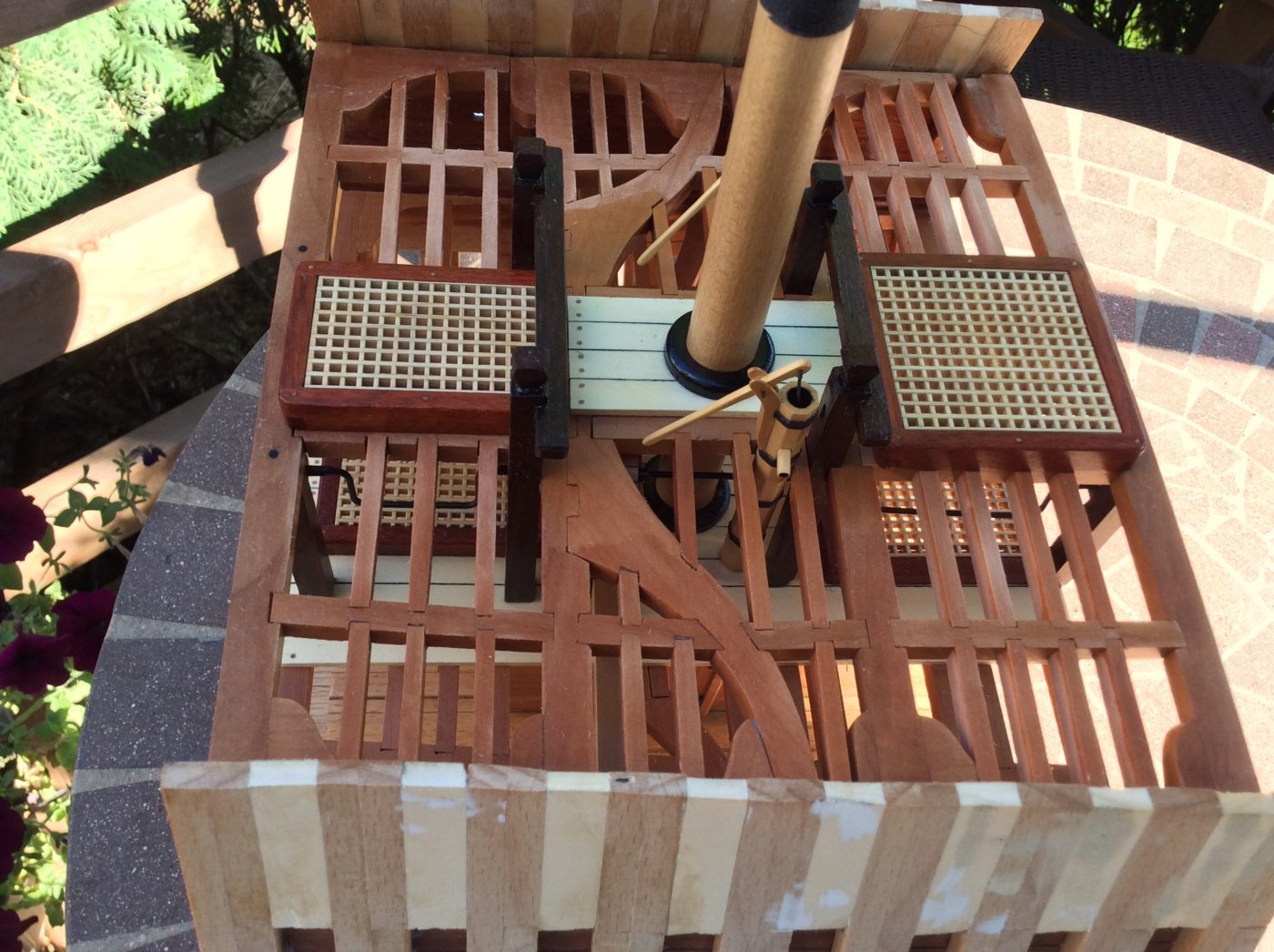
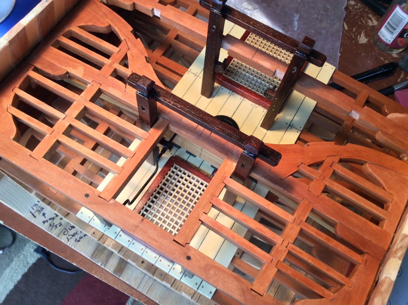
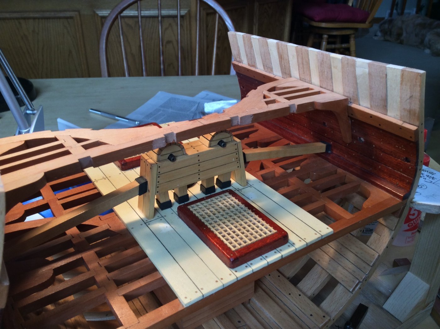
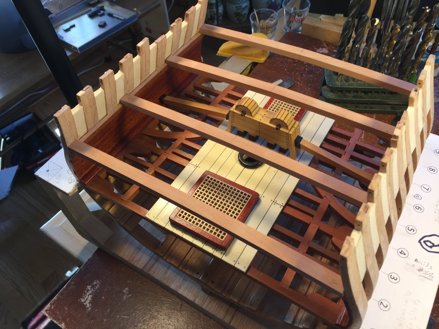
The main deck framing is complete. It still needs final sanding as well as planking and a couple of coats of poly. I'll plank the port side to accommodate 2 cannons and leave the starboard side unplanked.
Fitting the elm tree pumps was a real pain. They stand at an angle of 5 degrees, and the handles are long. If the handle placement is off the tiniest hair, the handle positions won't match and will be obvious because they are so long. Mine don't match perfectly, but I have to live with them!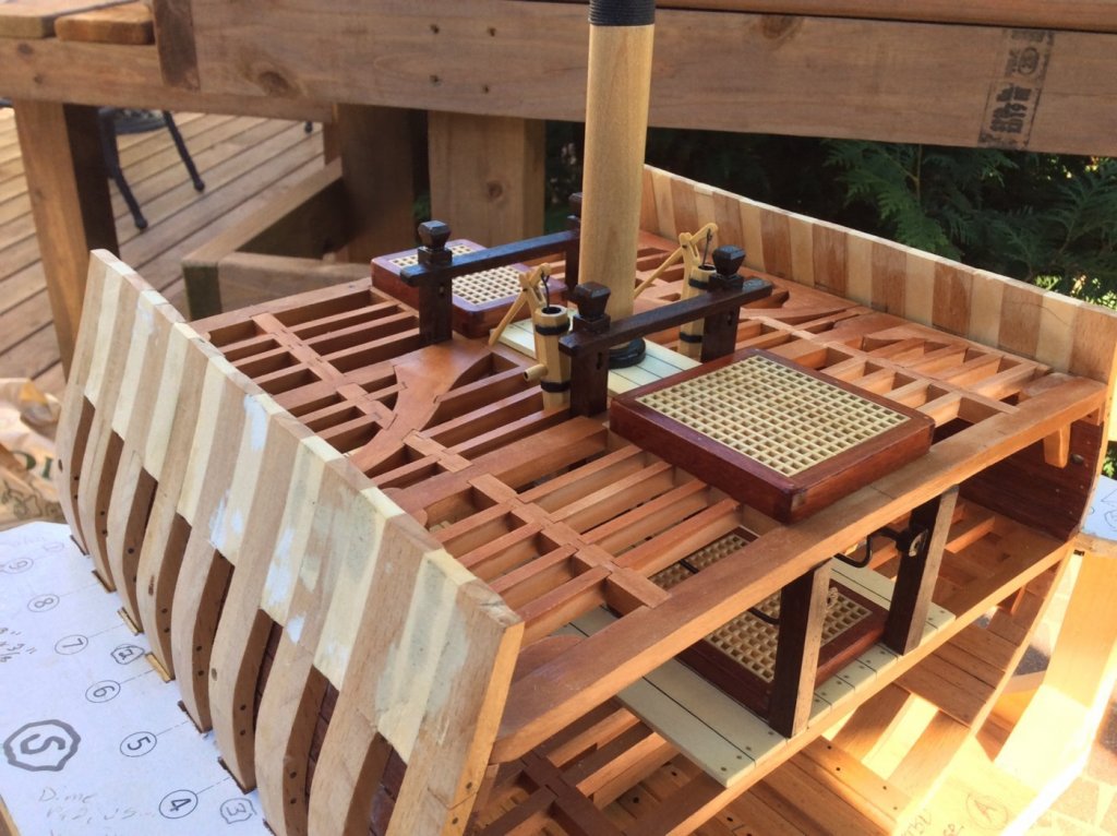

- Elijah, mtaylor, FriedClams and 11 others
-
14
-
The bands are actually shrink wrap used by electricians. Choose the proper size, cut off the bands, put them on the pump and shrink with a heat gun or put in a 300 degree oven for 5 minutes. Works well for banding on anchor stocks also!
- John Cheevers, FriedClams, MEDDO and 4 others
-
7
-
-
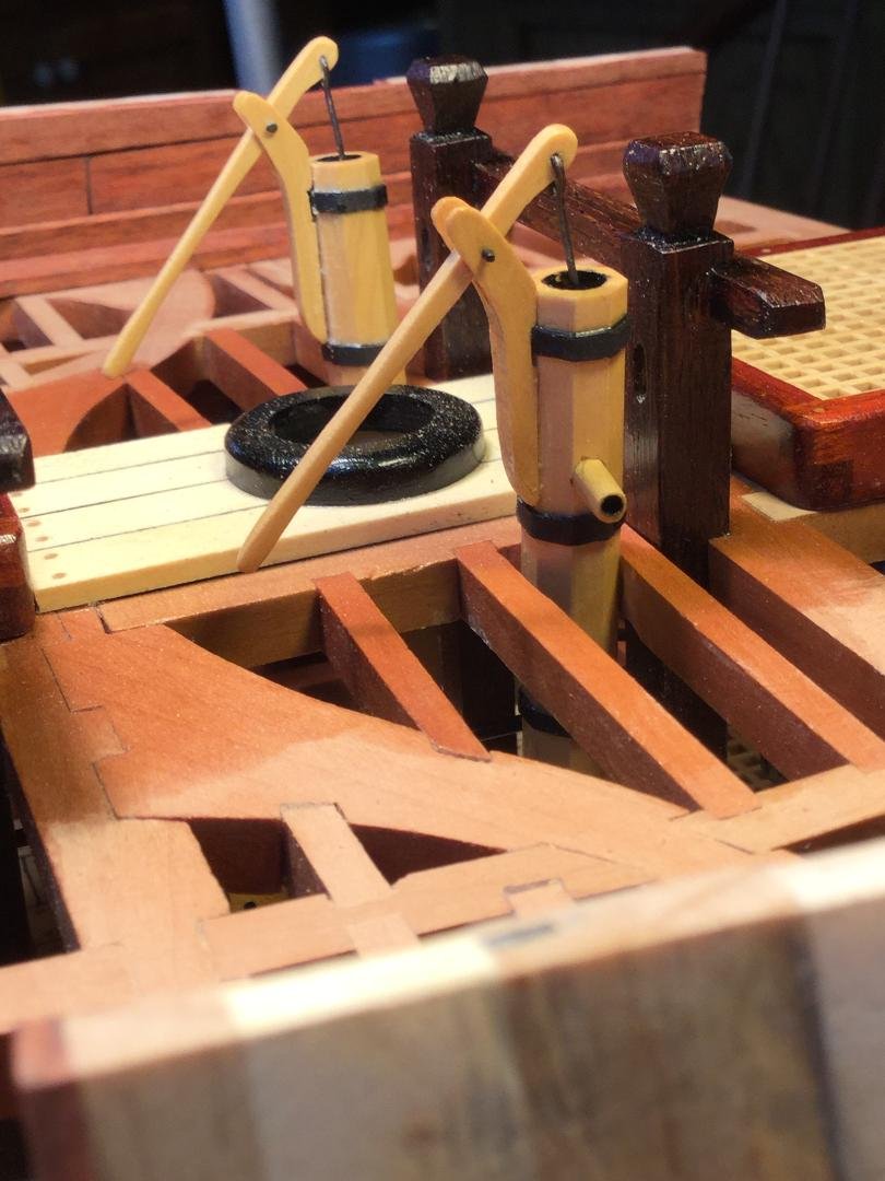
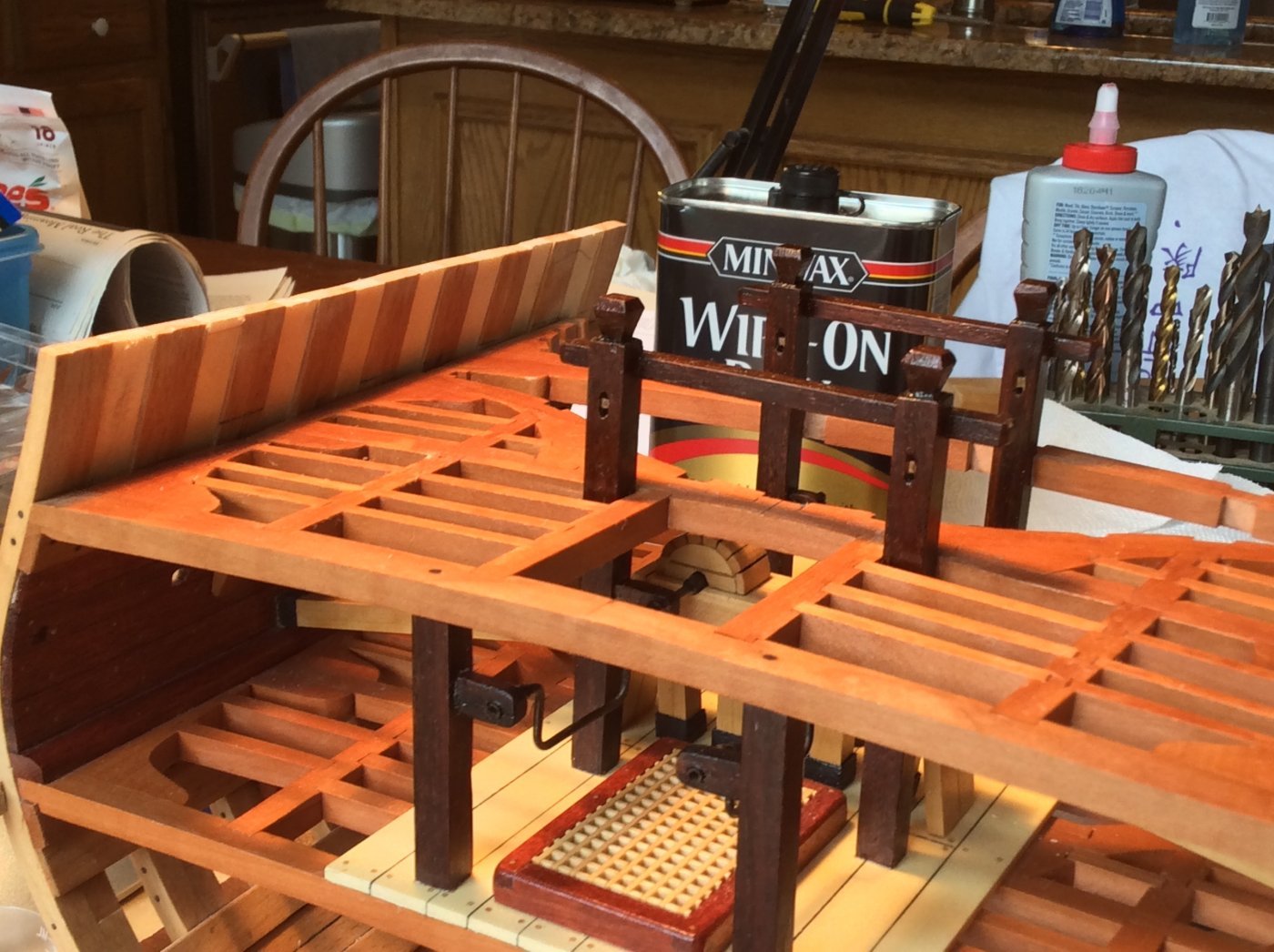
I need to install the elm tree pumps before I finish framing the main deck. I'll need access to the lower deck to pin and glue the pumps down.
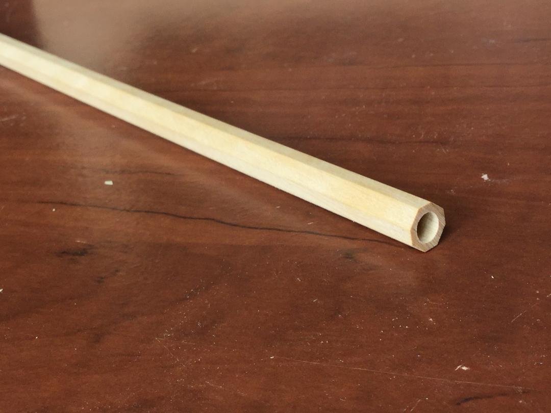
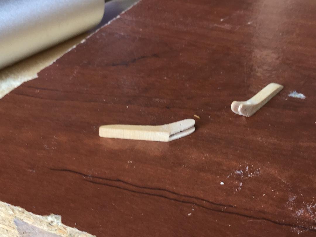
The first step is to cut a piece of 5/16" square boxwood into an octagon on the table saw. This isn't necessarily historically accurate, but I like the look. I found the center of the octagon on the ends and starting with a 1/16" bit, started drilling out the ends with successively larger bits until I got the size I wanted. The inside of the hole will be painted flat black. Then I made the handles and the brackets for the handles. I cut the handle brackets to size then used a razor saw to cut the groove where the handles fit. I enlarged the cut with first a single thickness of sandpaper, folded it to double and sanded some more then tripled it and finally finished with a 1/16" emery board. The handles are 1/16" stock. II still have to make the spigots. The pumps will be cut so they have a 5 degree "lean" from vertical so they can enter the well.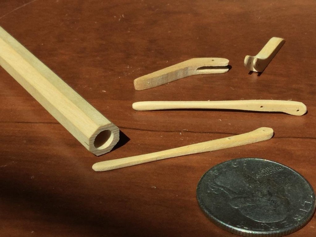


- rafine, FriedClams, bruce d and 10 others
-
13
-
-
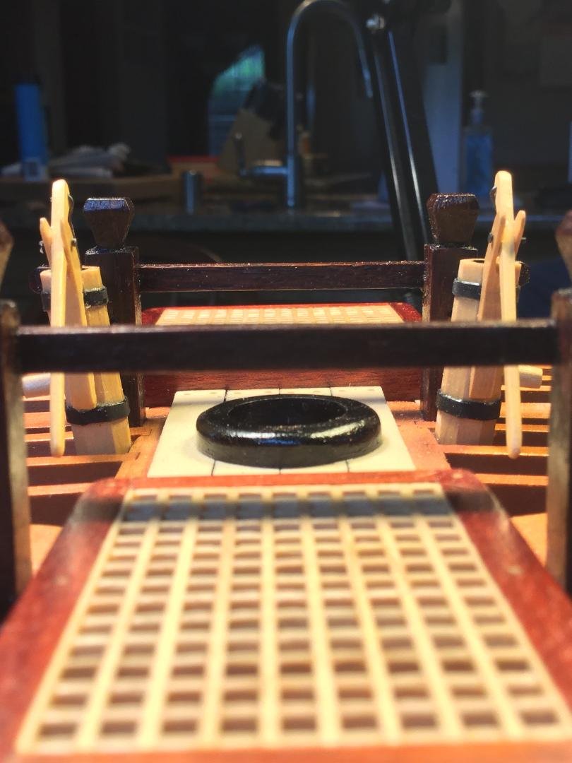
I agree with Mark. All the rings are the same diameter and wide enough to sit comfortably at the base of the mast.
-
It all looks great Bob! Just as we’ve come to expect!
-
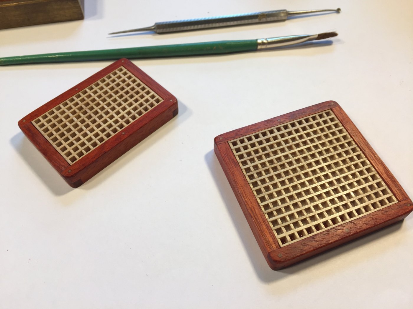
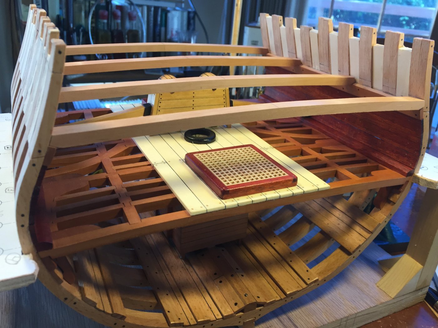
You caught me, Michael! I didn't realize it until I had glued the aft hatch on the lower deck in place that I left the grating a tiny fraction of an inch high. You can't notice it in real life unless you use your fingers, but at the magnification of the photos it shows up. My bad!
- Elijah, Canute, FriedClams and 1 other
-
4
-
-
-
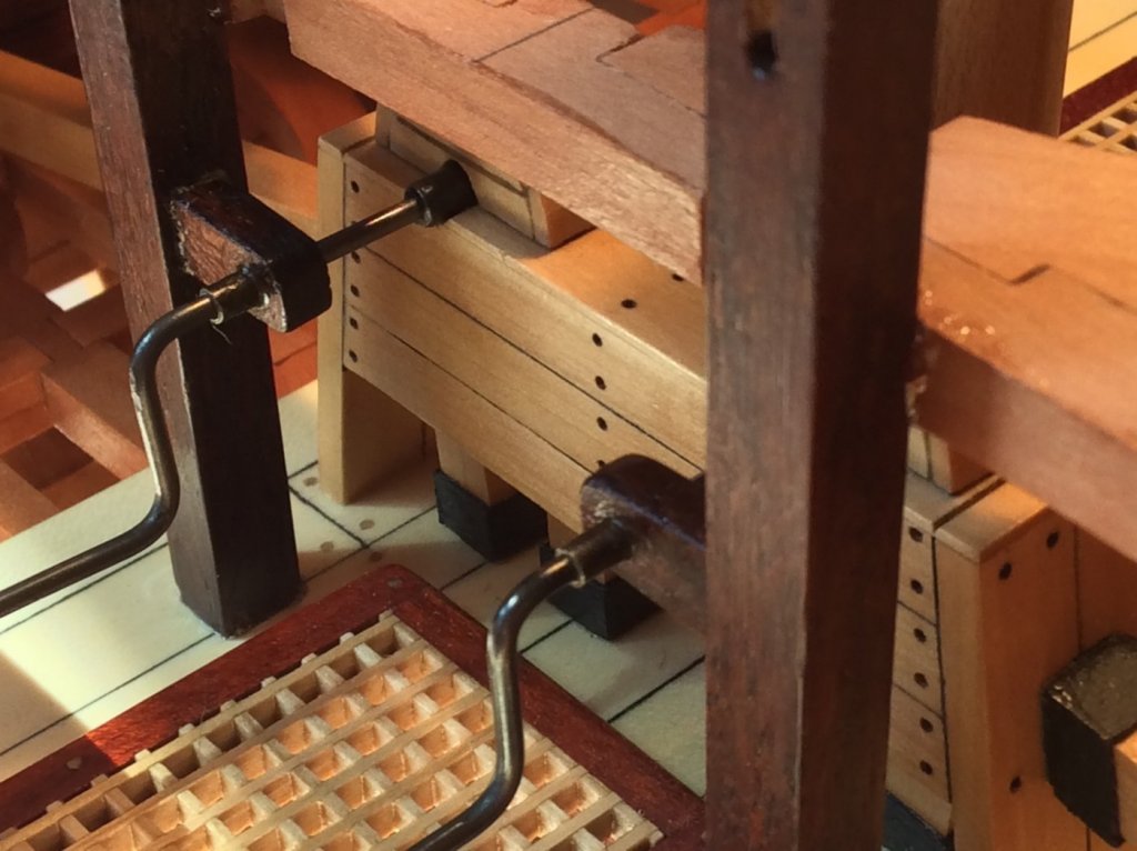
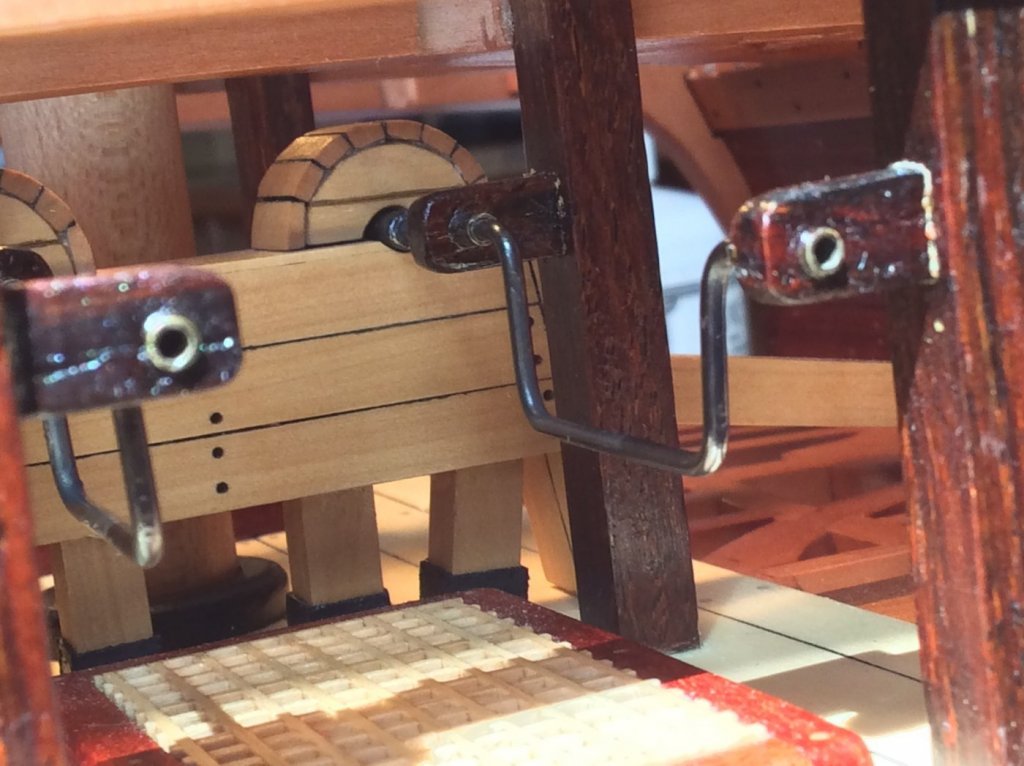
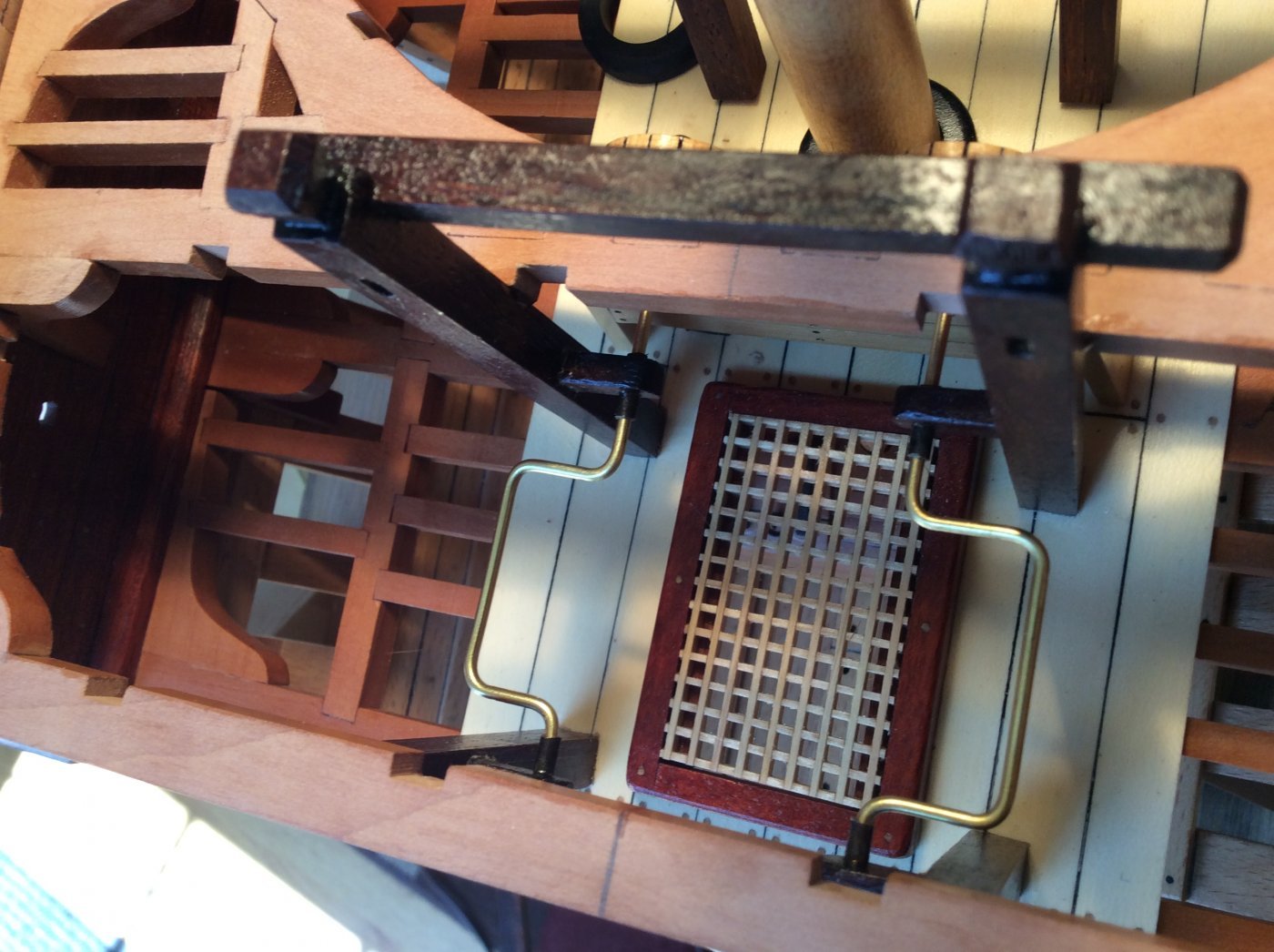
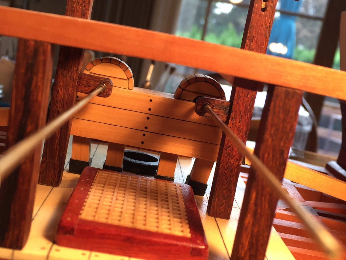
Blackened cranks. The cranks are completely blackened using Birchwood Casey Brass Black. The light areas on the last photo are from the sun's glare.
One word of caution: When you fabricate the crank handles, make sure the "offset" (where the seaman grabs the crank to operate it) isn't so large that it can't clear the two carlings that frame the hatch above. The plans show this to be a pretty close fit, so pay attention: smaller, rather than larger for the "offset"! I didn't want to anneal the brass for fear it would be too "floppy". It's hard to accurately bend 1/16" brass that's not annealed...it can result in an oversized crank. How do I know this???...………LOL!!
-
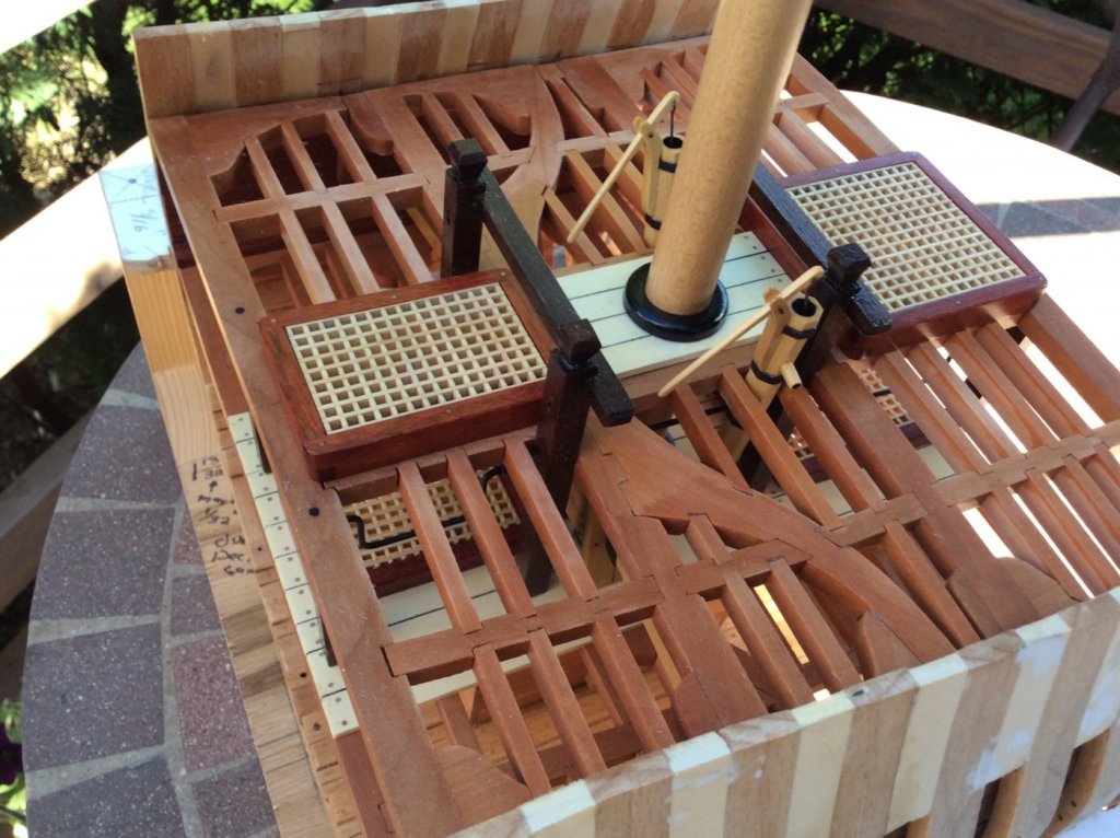
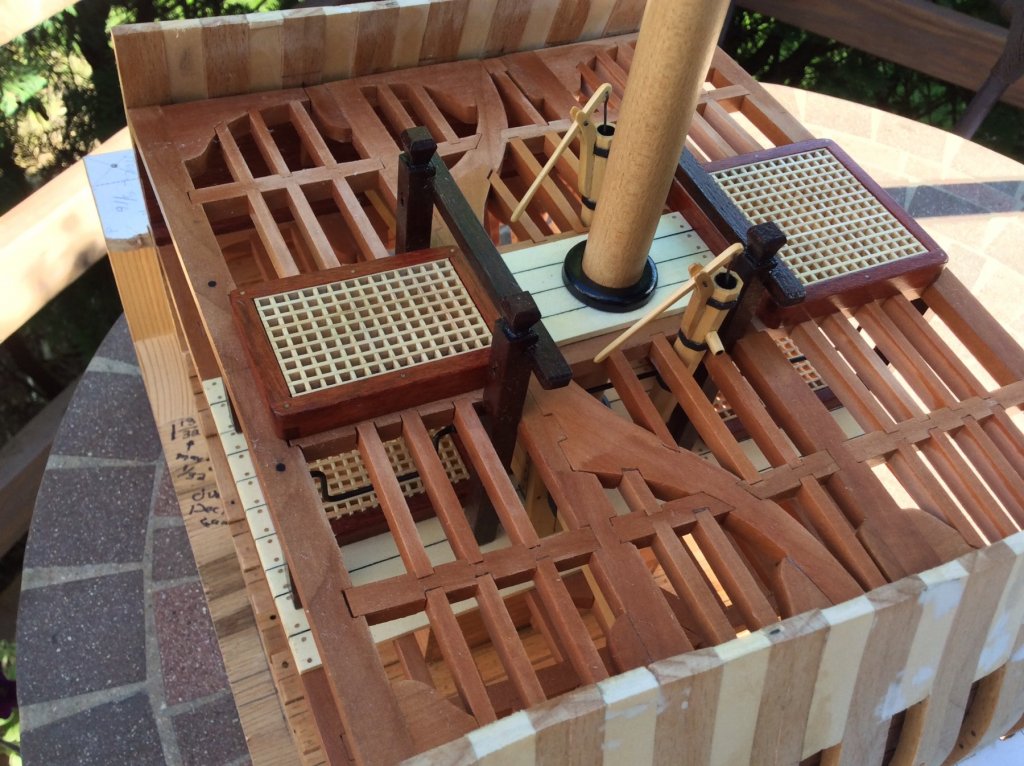
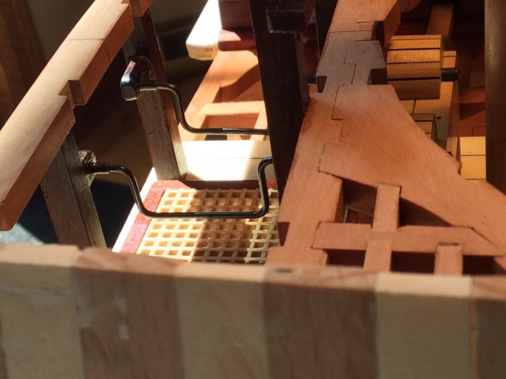
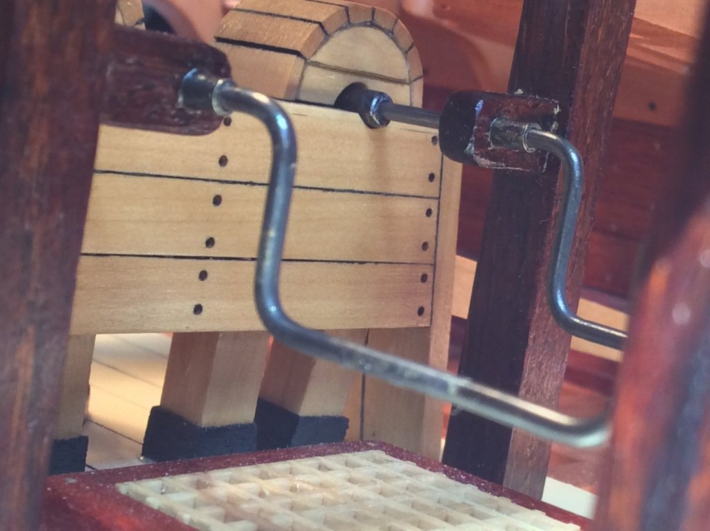
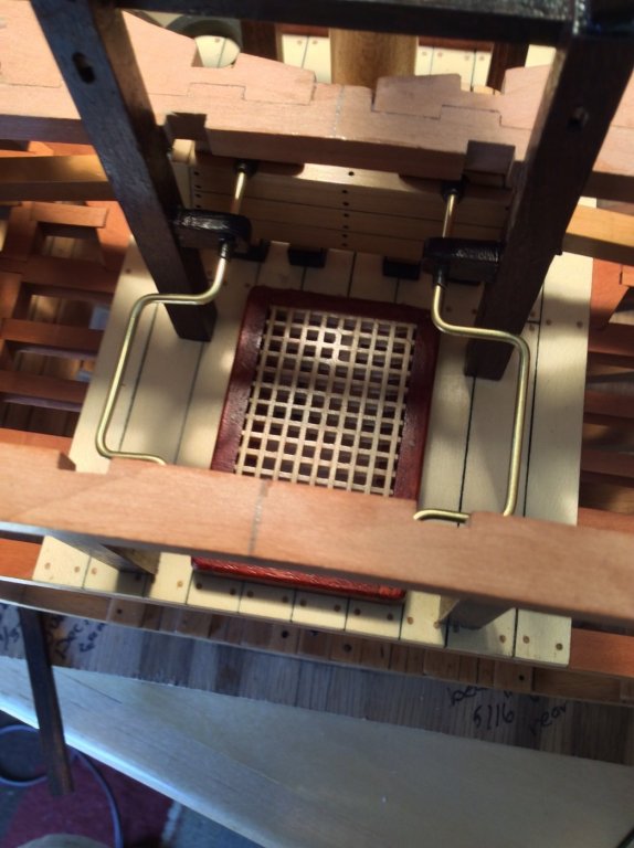
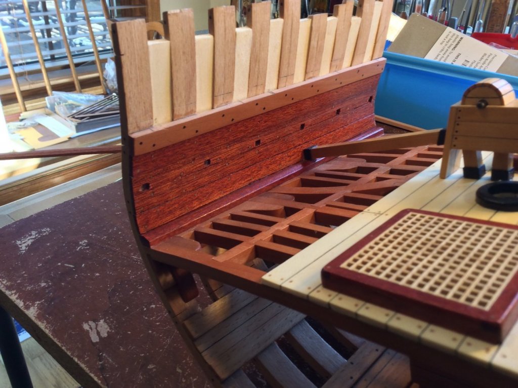
I pinned and glued the main jeer bitt to the lower deck as well as to the aft surface of beam 2. I then pinned and glued the support columns to the lower deck and used clamps to hold beam 1 in place, so the support beams underneath beam 1 stay where they are supposed to. I made the chain pump cranks of 1/16" brass rod. They need to be blackened.

- mtaylor, bdgiantman2, Zarkon and 16 others
-
19
-
Thanks, guys!
I finally trimmed the top of the bulwarks to their finished length. I also used a little wood putty (I used a Dremel sanding drum for rough shaping) to fill in a few boo-boos, then sanded everything smooth. I just epoxied beam 2 of the main deck in place. Main deck framing along with finishing up the chain pump crank handles are next.
- hamilton, rafine, usedtosail and 12 others
-
15
-
Thanks, Yves!
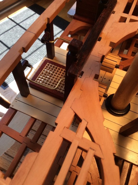
This is a complicated part of the build because several things are happening at once. This is how I plan to approach it:
1) Measure and fit the two pillars supporting main deck beam 1 and install the support pieces and bearings.
2) Pin and glue the pillars to the deck and glue them to the underside of beam 1 while gluing beam 1 to the deck clamps (use epoxy)
3) Fit and glue the two carlings that support the aft hatch.
4) Pin and glue the main jeer bit to the lower deck and glue it to the two aft hatch carlings. Also epoxy.
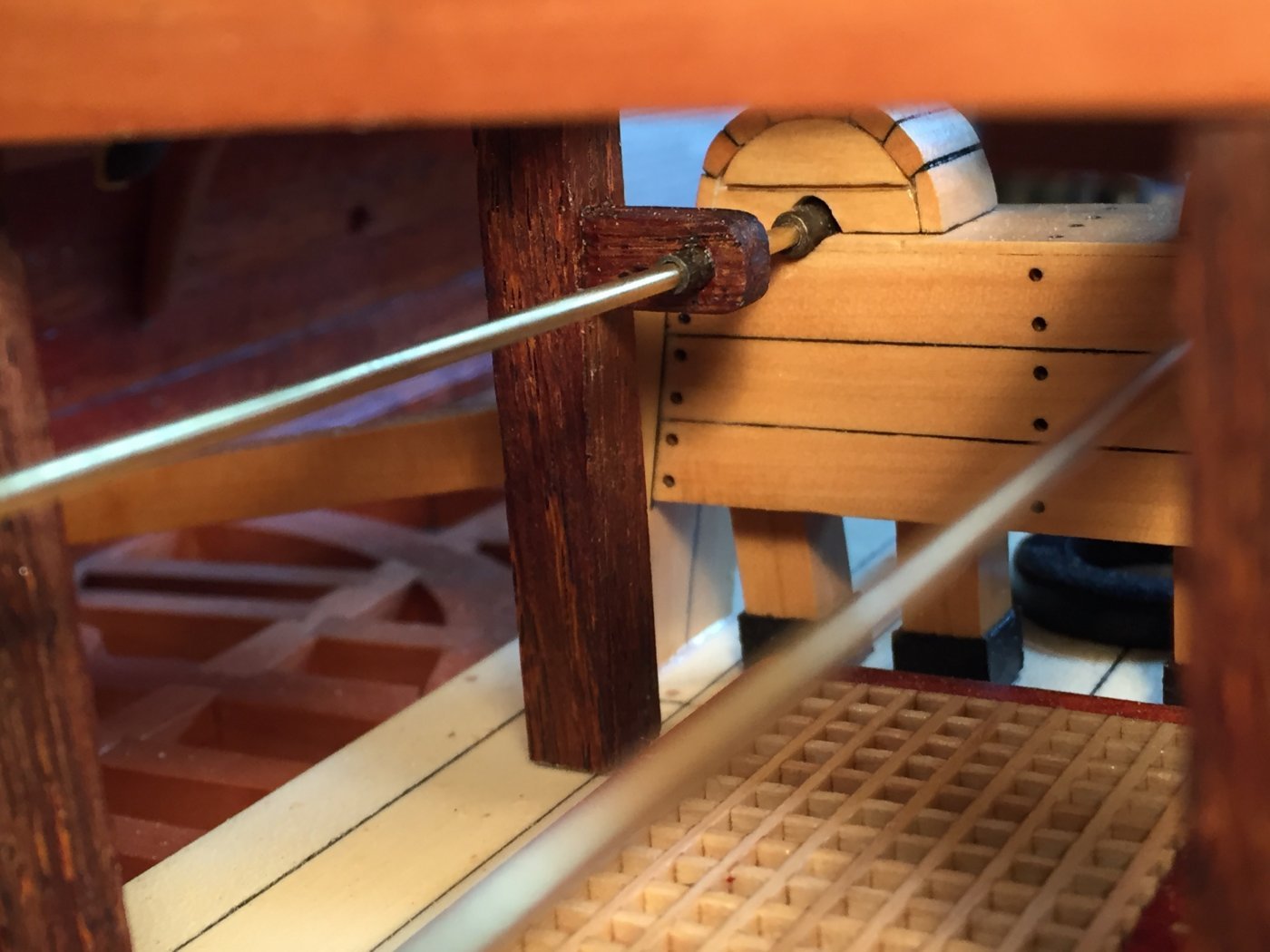
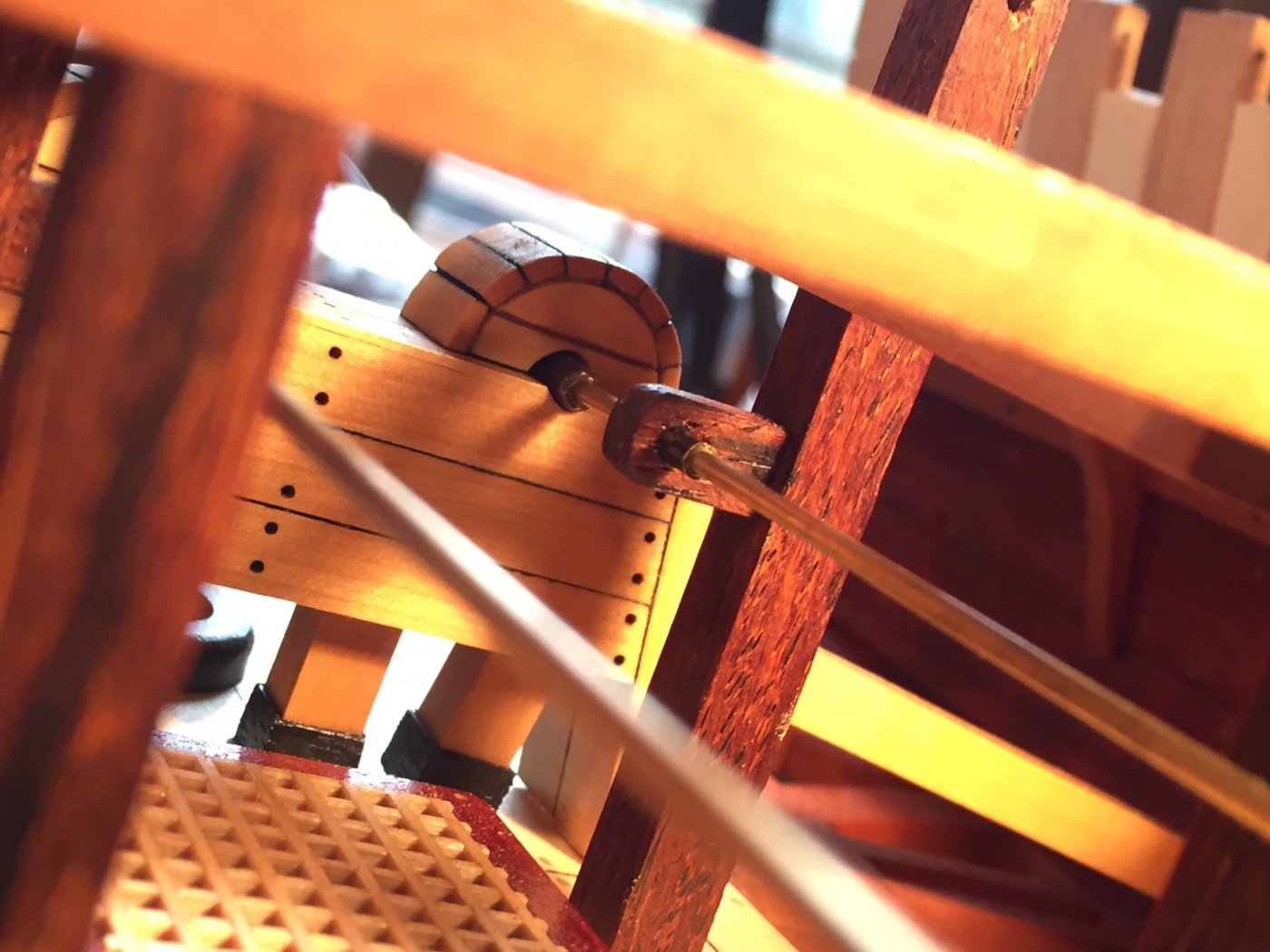
5) Fit the cranksHere is the bitt sitting in place, with the support beams in place, but bearing support pieces not yet attached. I fit two pieces of 1/16" brass (not blackened) to check the fit.


-
-
Thanks, J P!
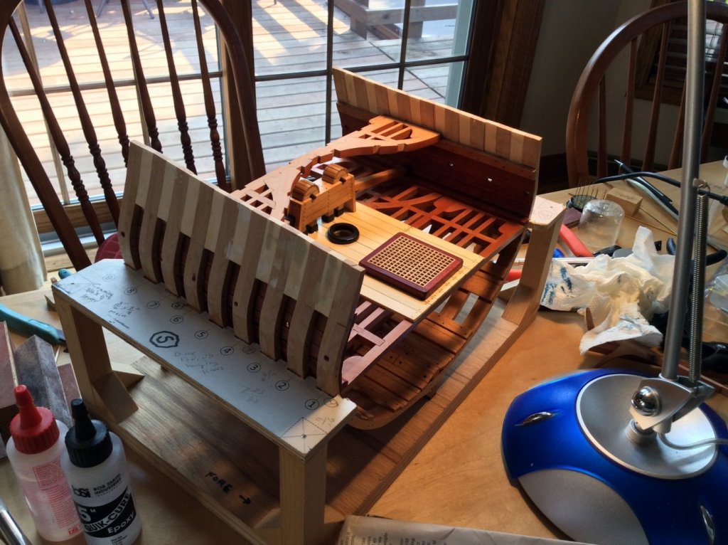
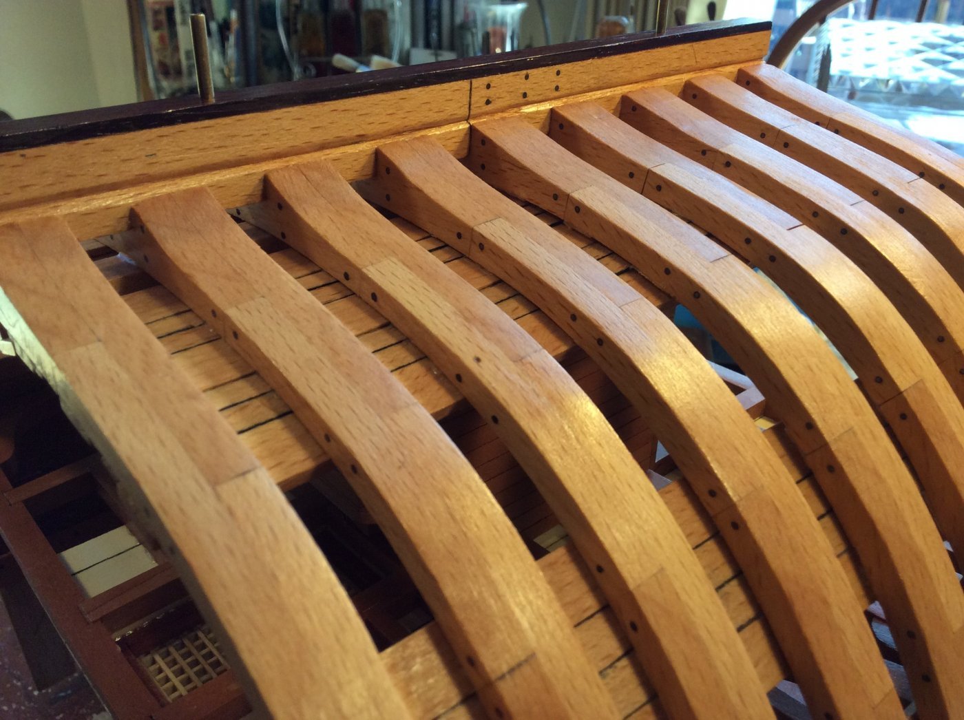
I trimmed each frame so they flowed nicely into the rabbet. I then gave the frames a couple of coats of poly. I also cut out the sweep ports on the inboard bulwarks.
Slow going as I line up and measure the supports and the bearings for the chain pump cranks and attach them to the bitts and pillars. The last photo shows the main jeer bitt with the supports and bearings in place.


-
-
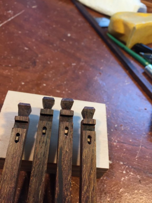
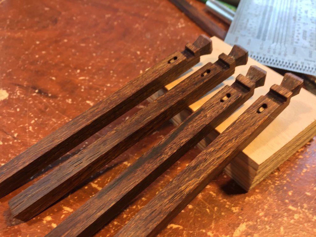
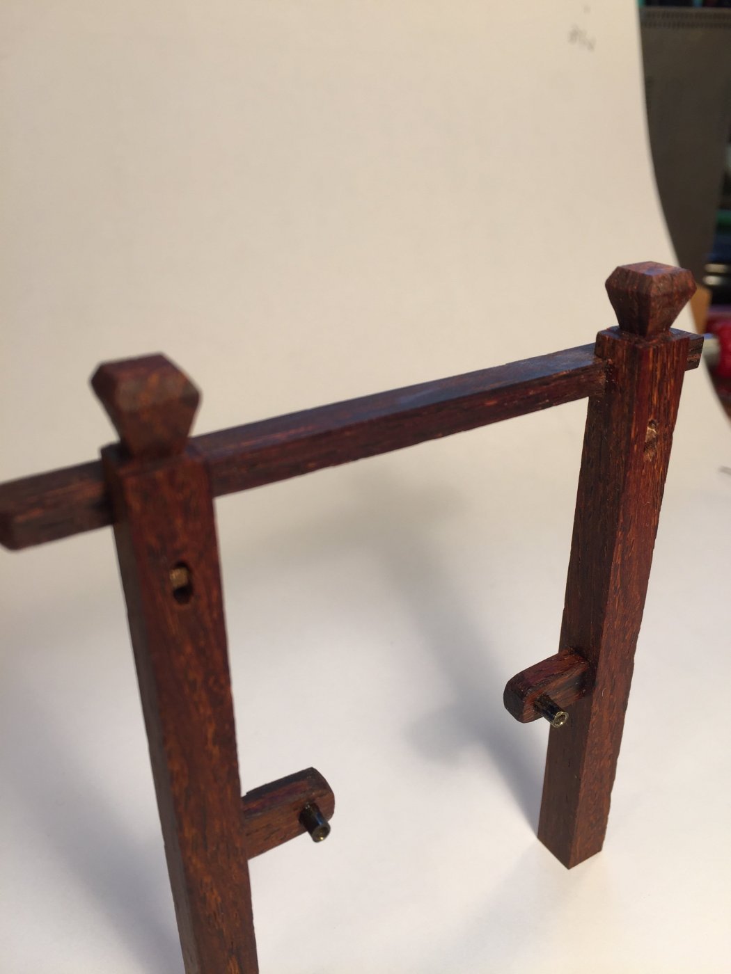
I'm laying out and gluing together the main deck beams with their assorted knees. I'll fix these in place before fitting carlings and ledges, as I did with the lower deck. The problem is that this is a very complicated part of the build because simultaneously with building the main deck, you must complete the chain pump crank mechanisms and their supports, which are attached to the mean jeer bitt, the topsail bitt and 4 columns between the lower and the main deck. I started with the bitts. Here are 4 vertical timbers that will make up the two bitts, with their simulated sheaves and rabbets for the cross pieces. Here they are before trimming, and without poly.
-
Great work, Bob! Good to see you back!
-
Tuning back in. Nice progress! She is coming along well. The extra time and detail will pay off in the end. Keep going!
-
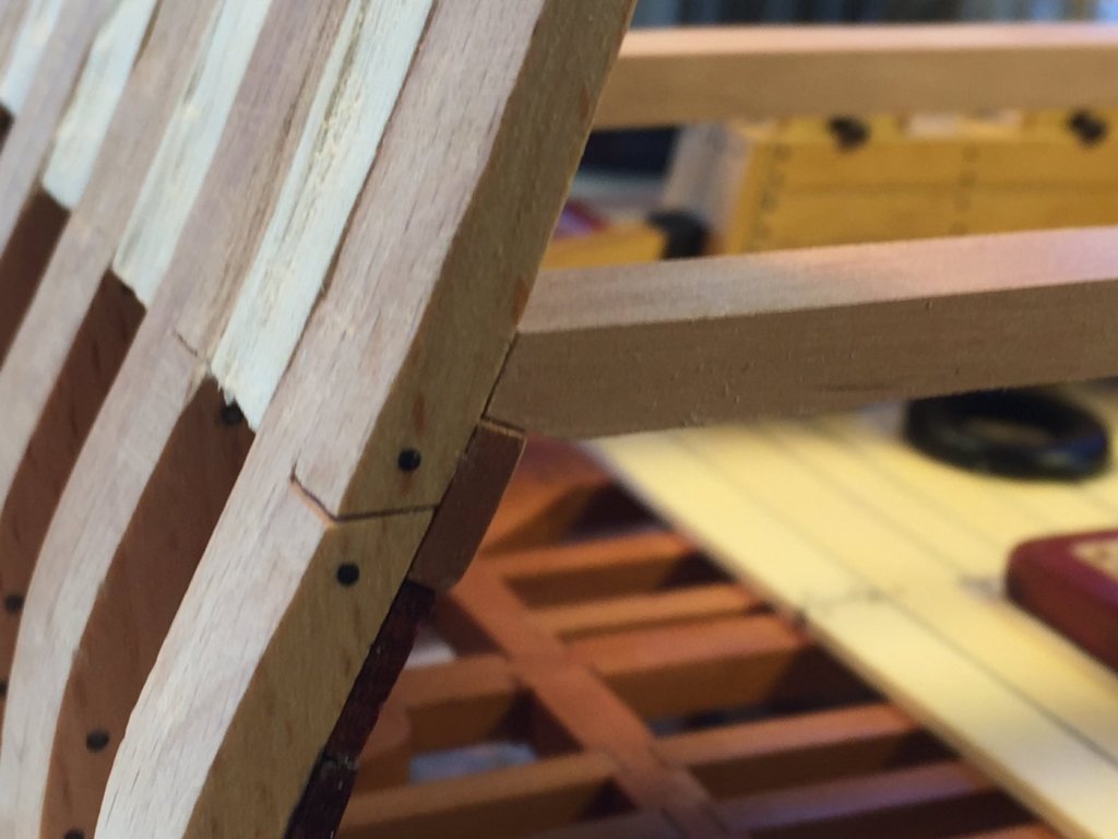
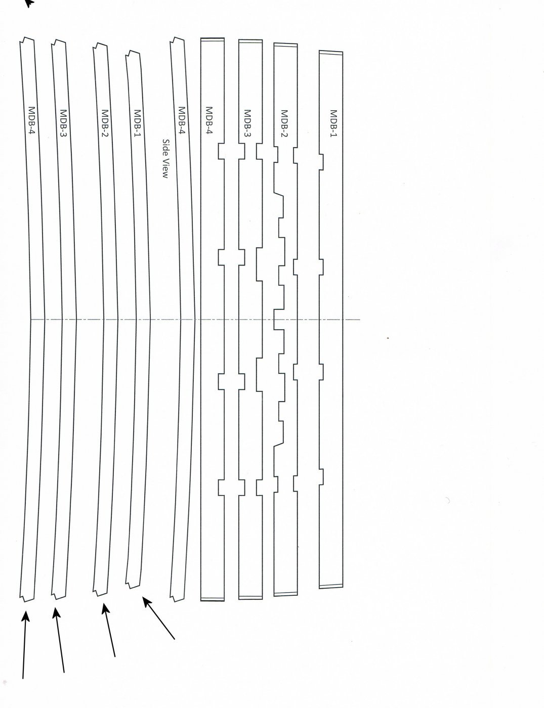
I cut out the four beams for the main deck. The 3/8" wide and 1/4" thick. There is a discrepancy in the plans regarding the main deck beams, so I had to lengthen them to fit. I took my time fitting them in place on the main deck clamp. To make that easier, I modified the ends of the beams. According to the plans, there is a little notch that fits over the top and the face of the clamp. I eliminated the notch, leaving a "flat" - much easier to fit in place.


Discussions about chapter one - Bulkhead material-skeleton framework for Winchelsea
in General project discussions on planking, fittings and monograph chapters
Posted
Chuck: Assuming birch ply for the false keel and lite ply for bulkheads, cut out with a scroll saw, how many 12” X 24” sheets of each are needed for the project?