


DocBlake
-
Posts
1,811 -
Joined
-
Last visited
Content Type
Profiles
Forums
Gallery
Events
Posts posted by DocBlake
-
-
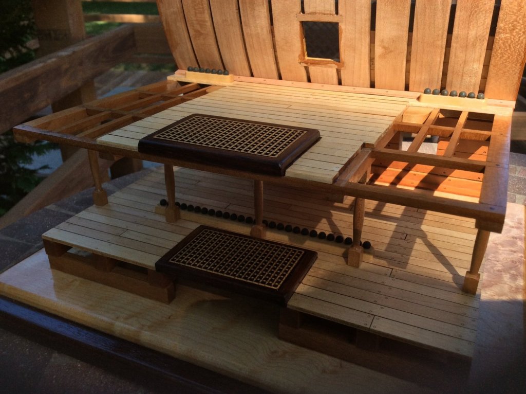
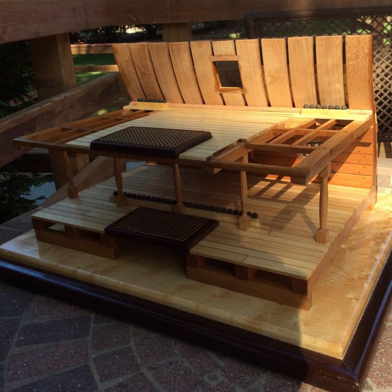
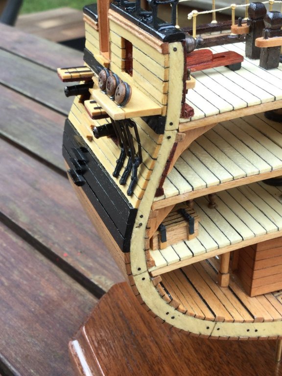
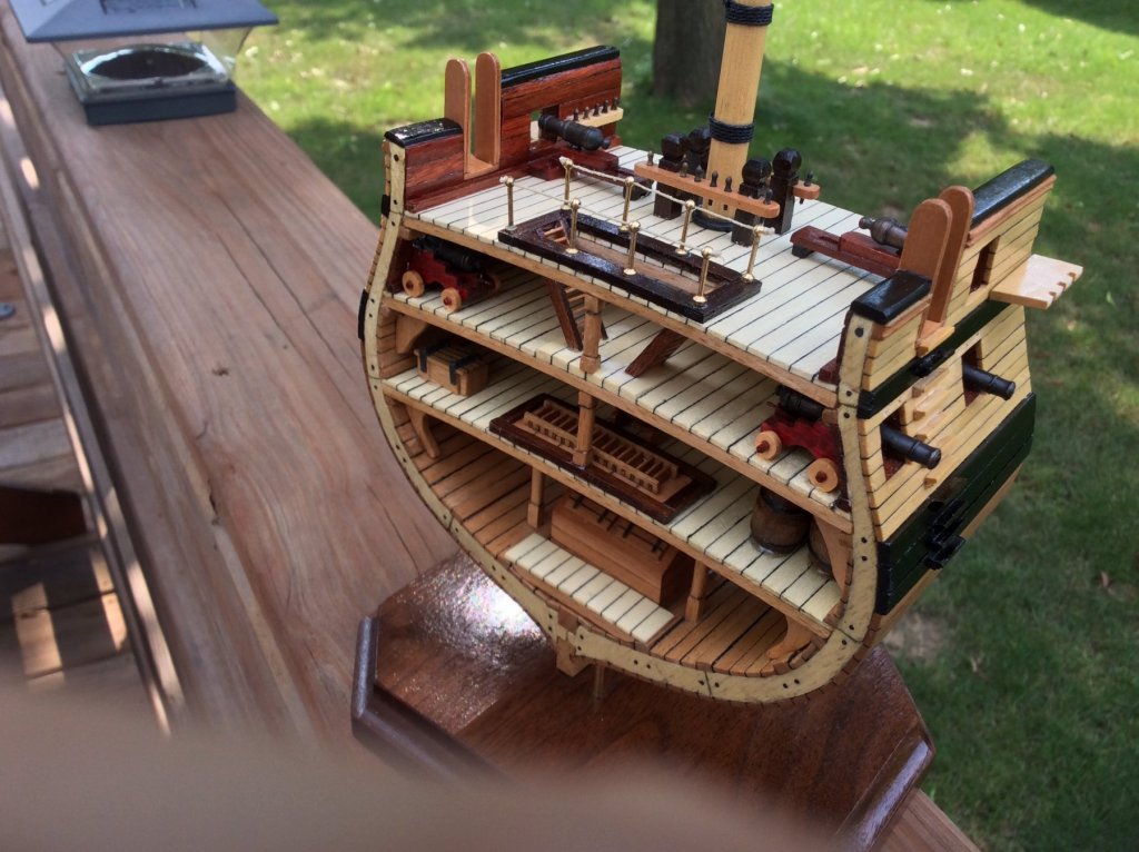
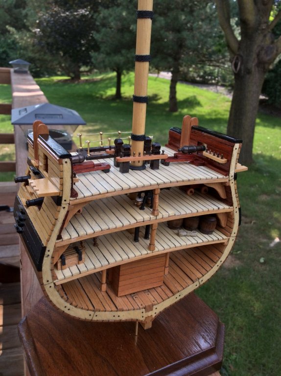
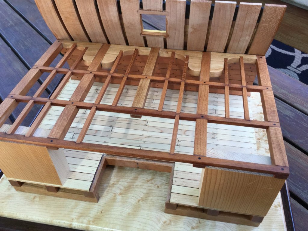
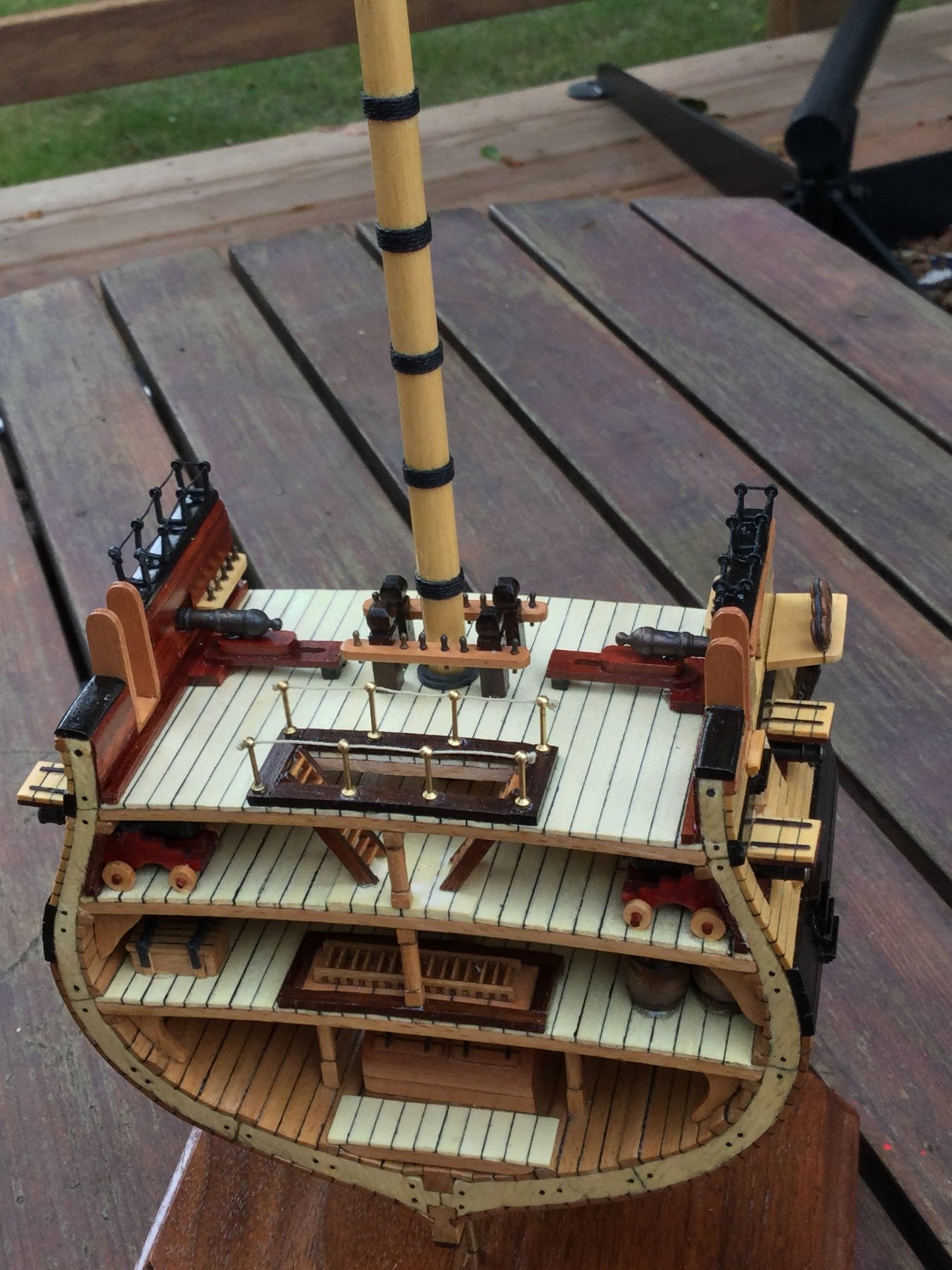
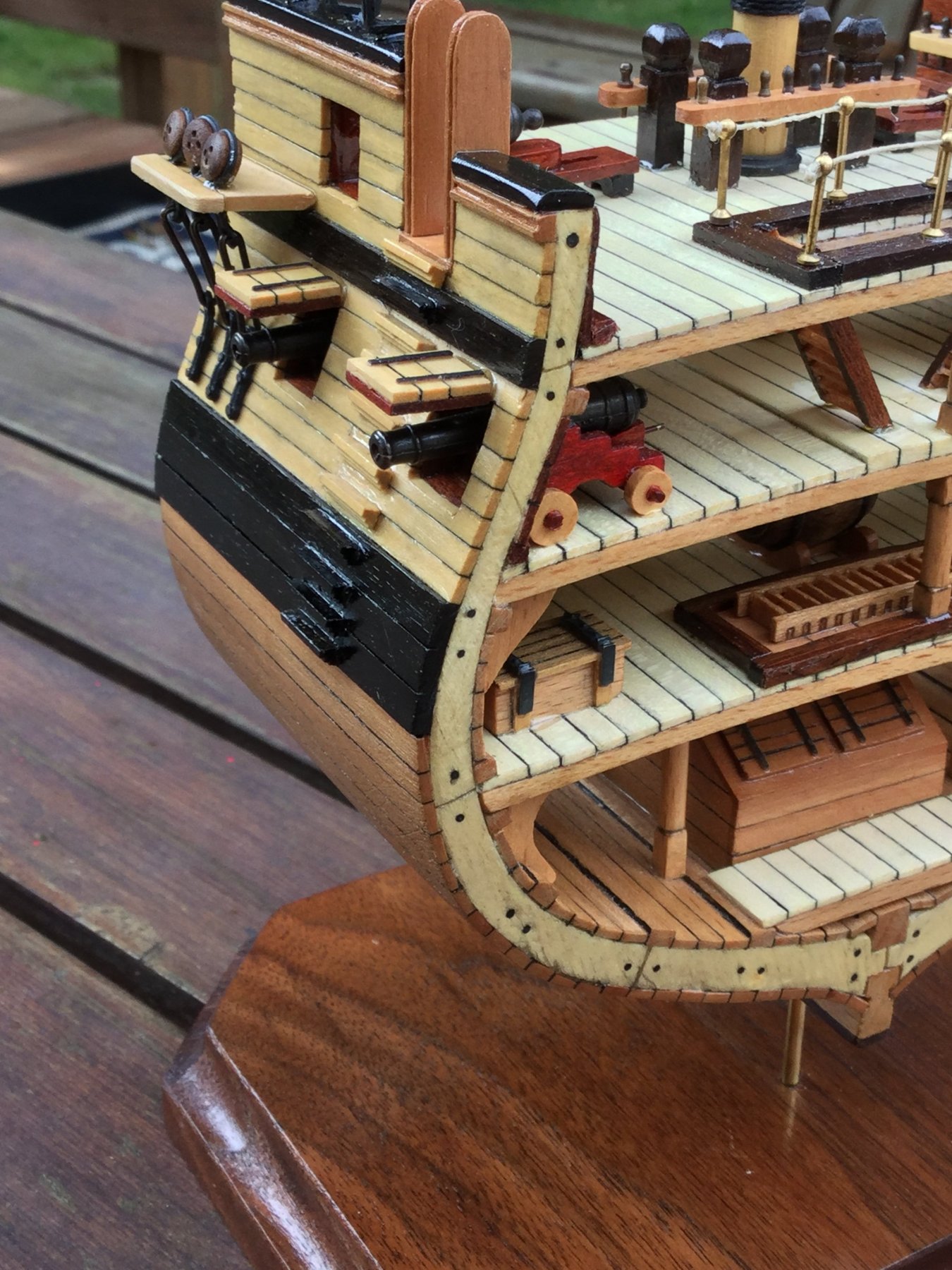
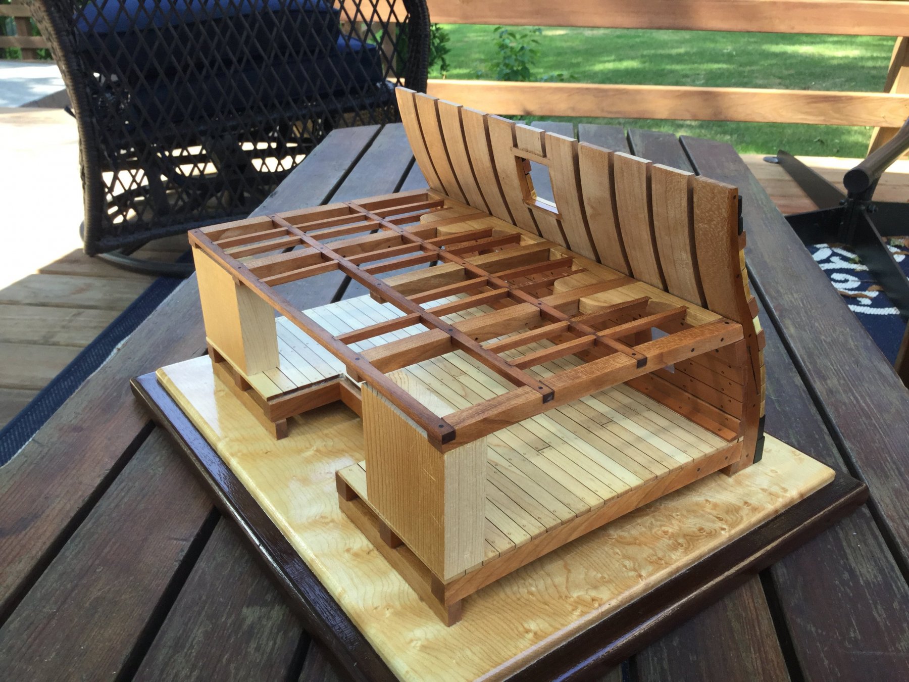
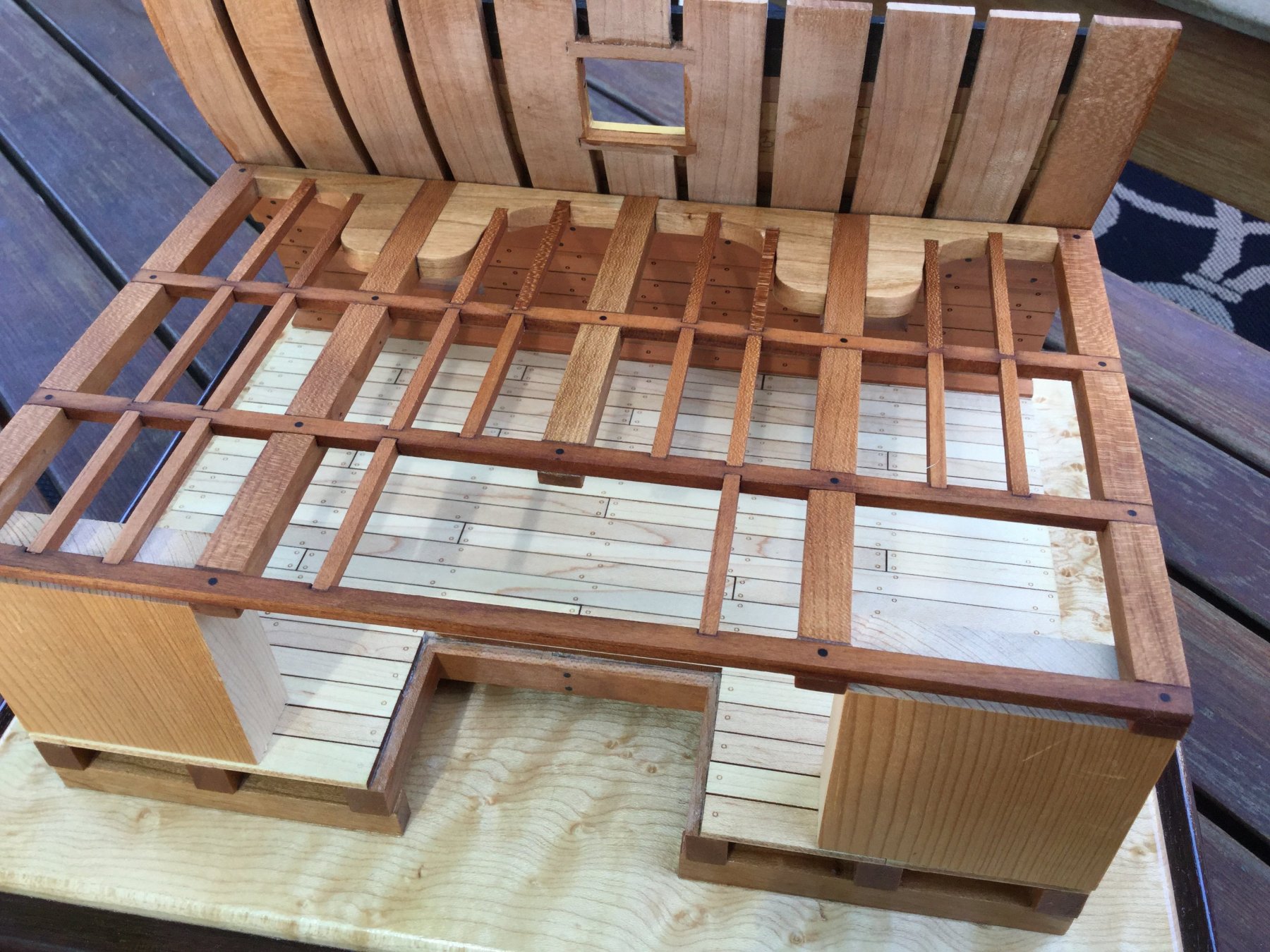
I finished planking the upper deck, installed the hatch coamings and the upper hatch and finished off the shot racks. The upper deck is just sitting in place. It won't be installed until the guns and details on the lower deck are complete. It is tight in there! The 2 hanging knees at the ends will be glued in place once the upper deck is in place. Next is the guns.


-
-
-
-
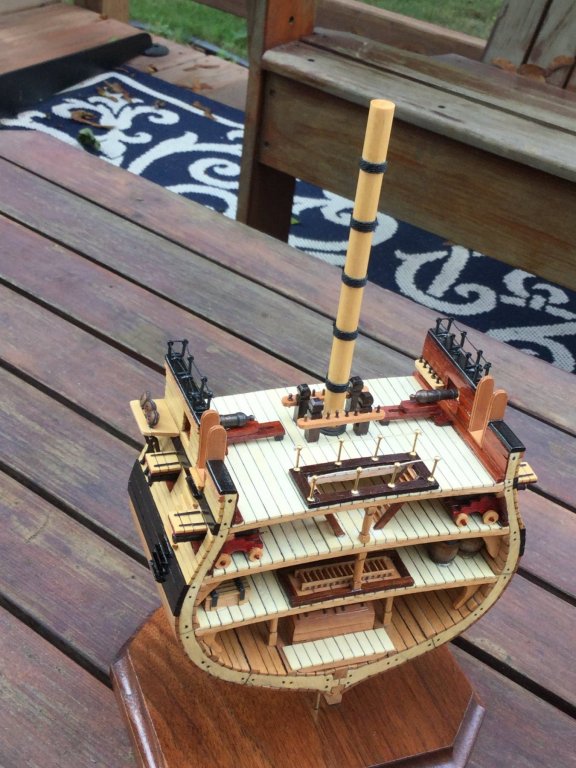
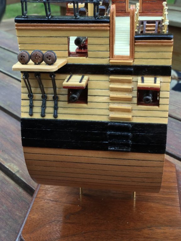
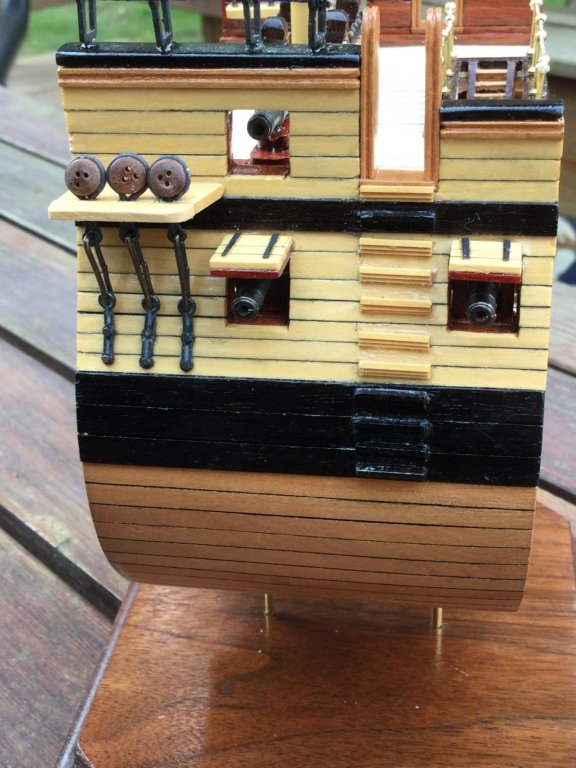
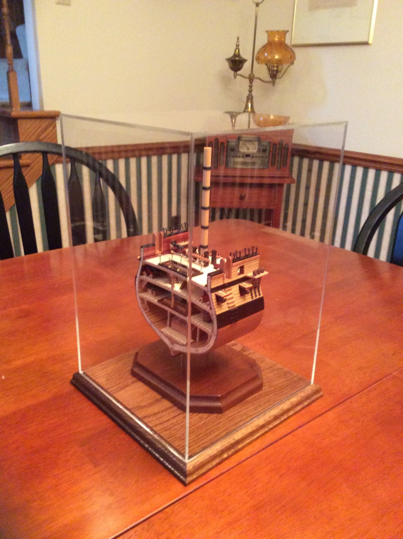
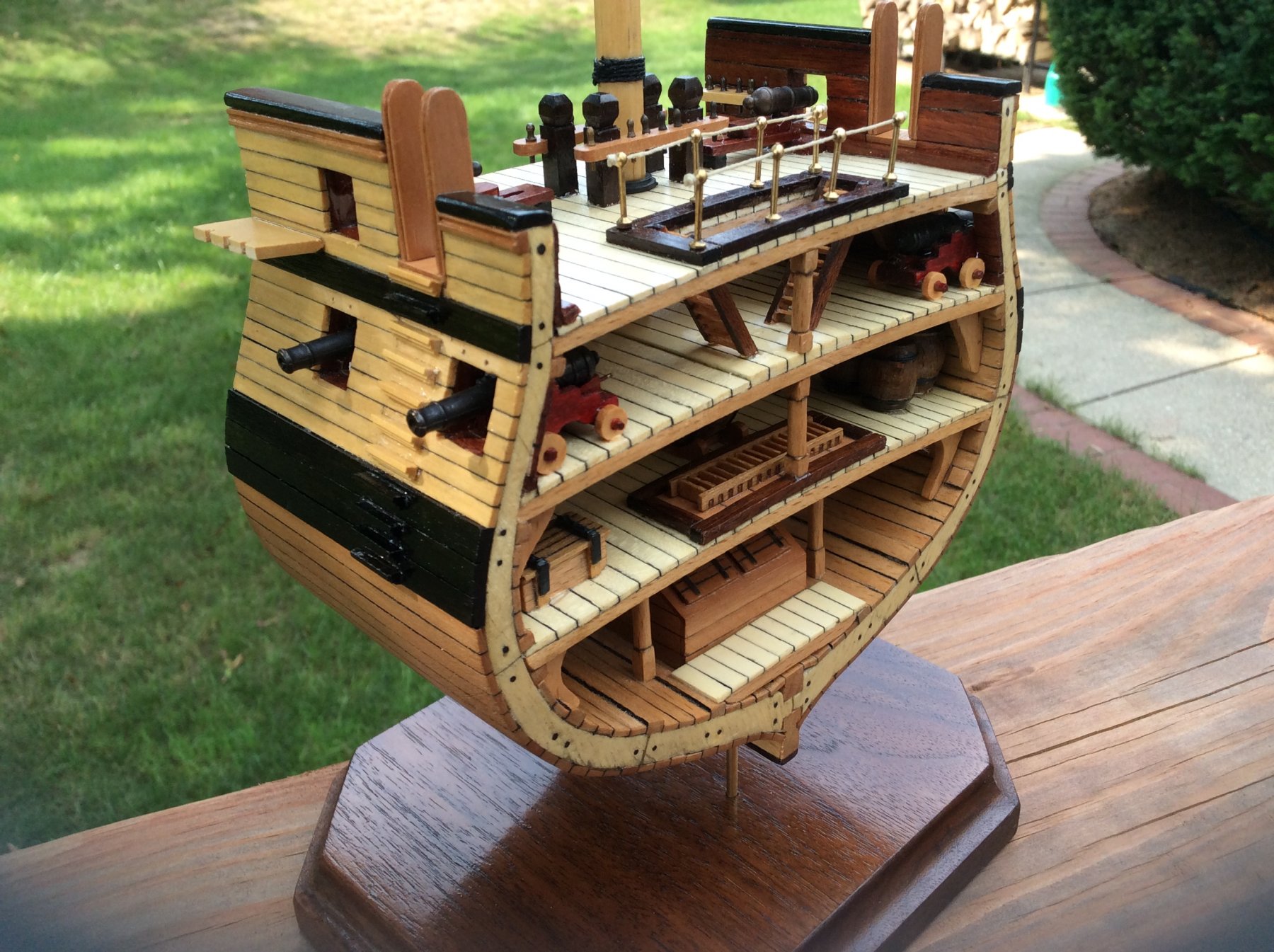
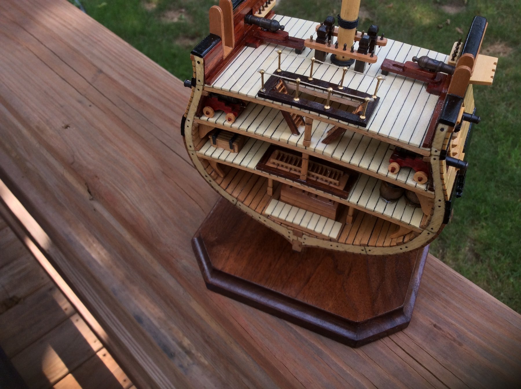
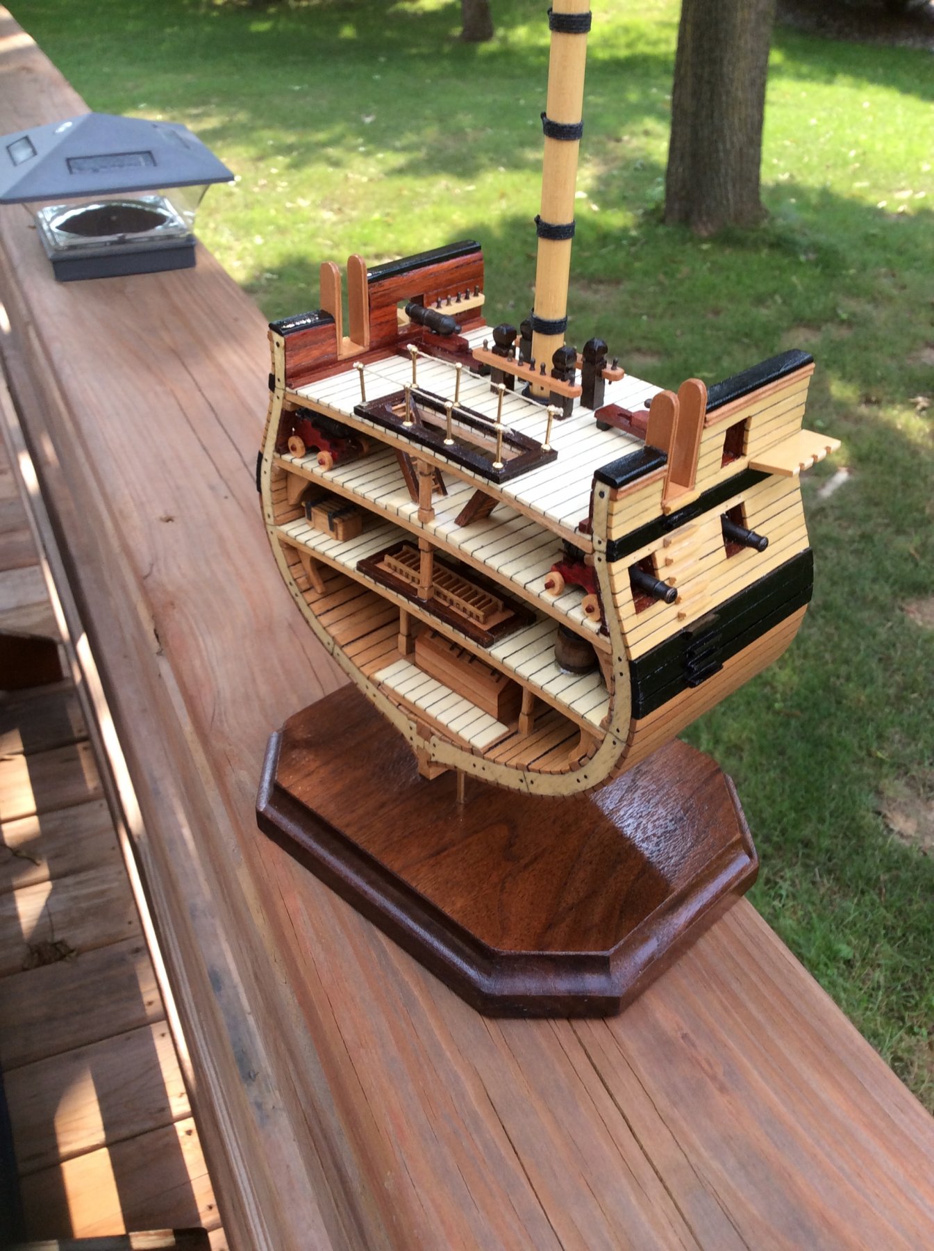
Finally finished!!!
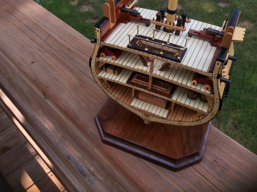
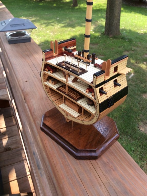
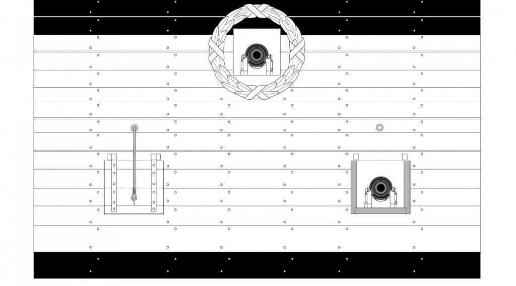
I added the last details to the cross section. The hammock netting supports were mounted and I rigged them with some black line. This was a style decision, not a historical one. I chose not to add the netting itself. The deadeyes and chainplates were installed next, with a small strip of boxwood glued to the outboard end of the channels to keep them in place. Last, I added the 4 gun port lids. Again, I chose not to rig them.
This was really a fun build, and I ended up with a model that was completely different from what the kit intended. To me, that is the real fun. Thanks for watching, everyone!


- Canute, marktiedens, yvesvidal and 8 others
-
 11
11
-
Nice work, Bob! Are you planning to rig the gun port covers?
-
Thanks, Bob, and everyone for the "likes".
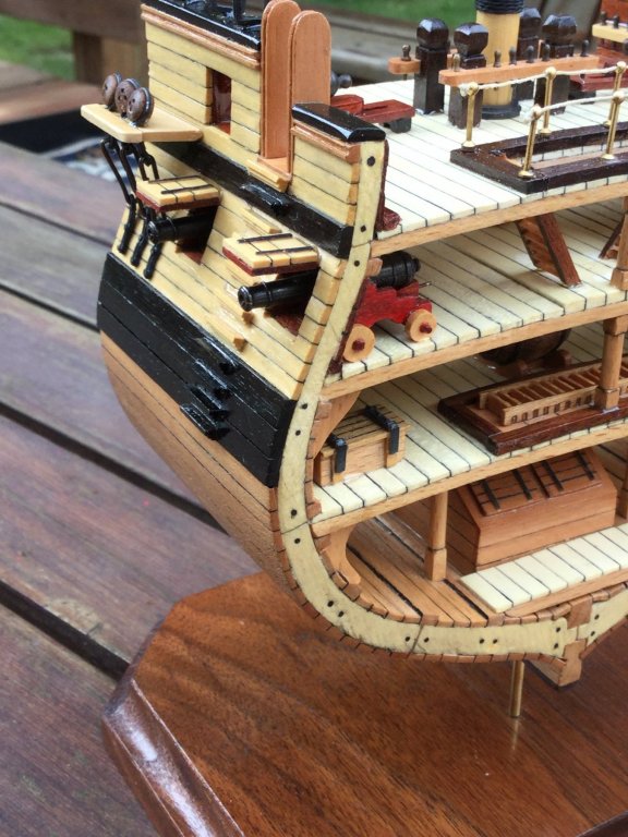
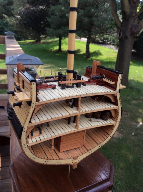
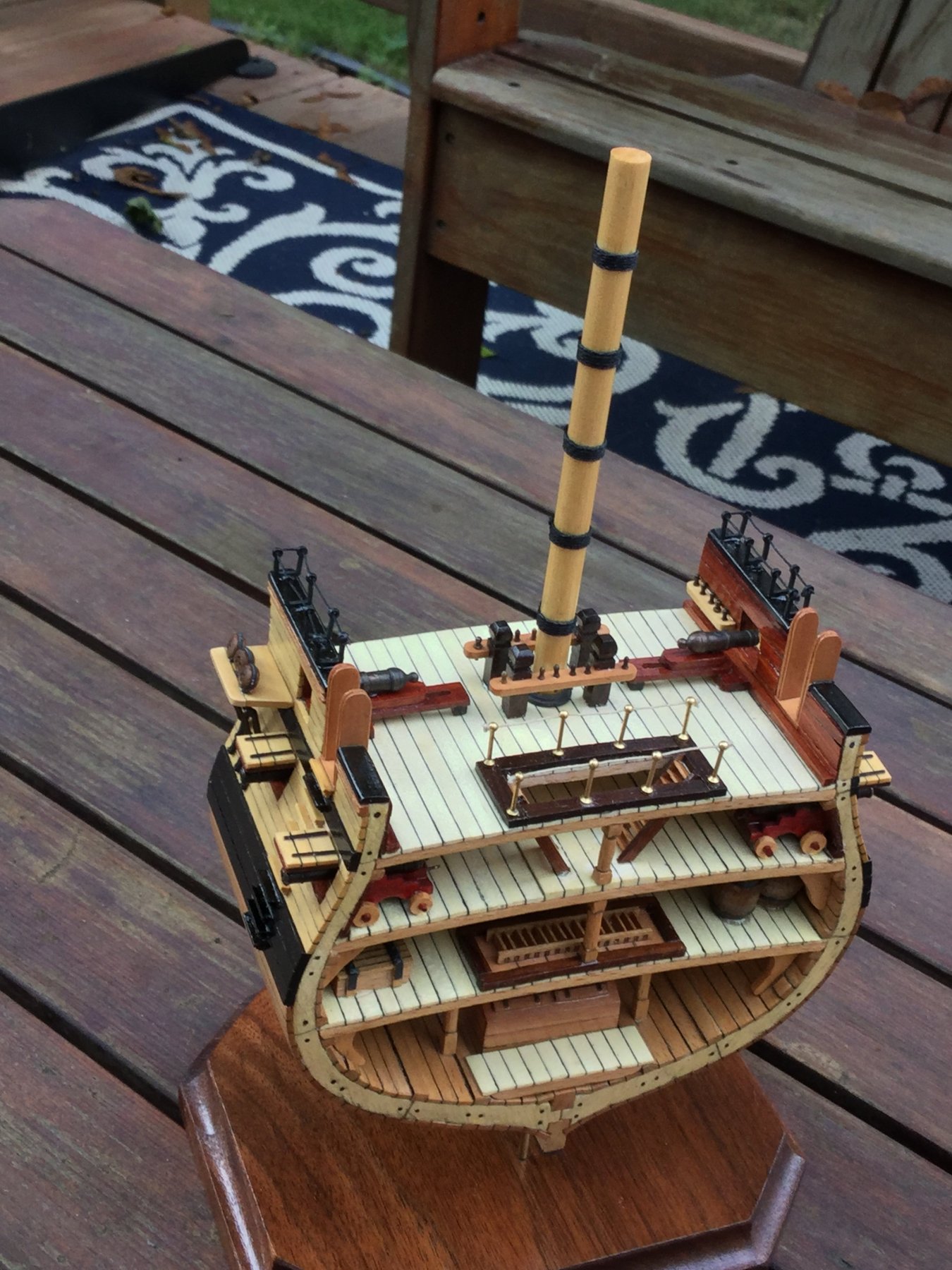
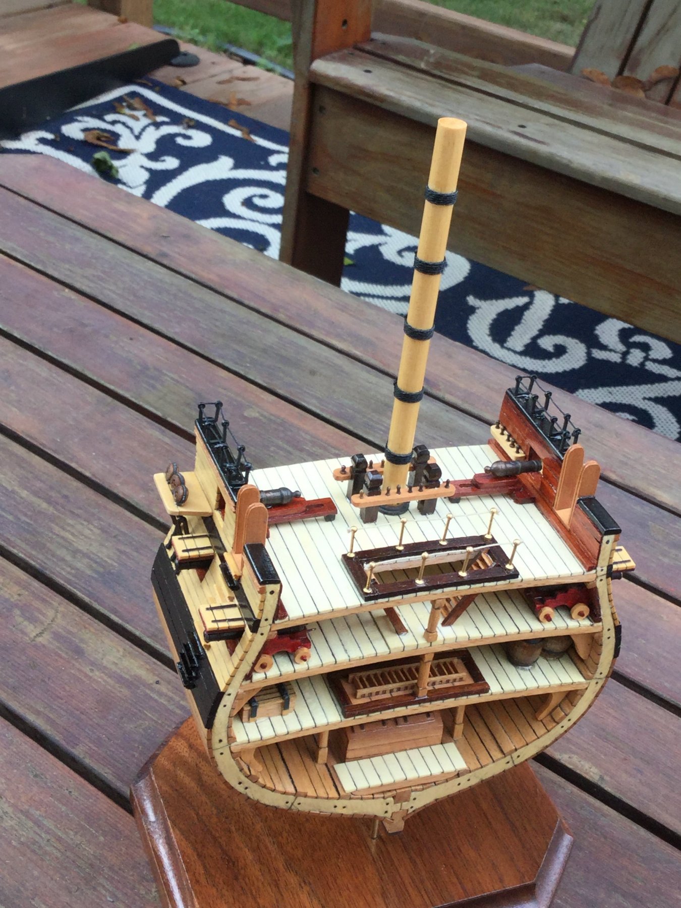
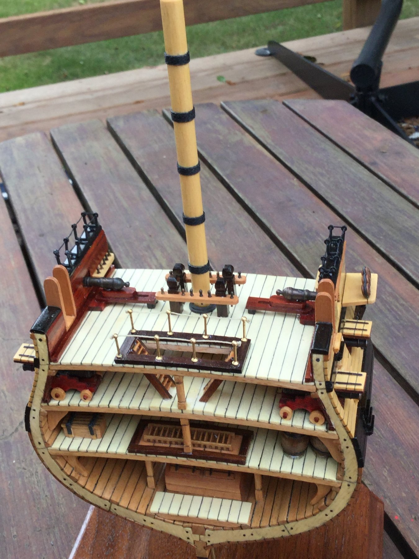
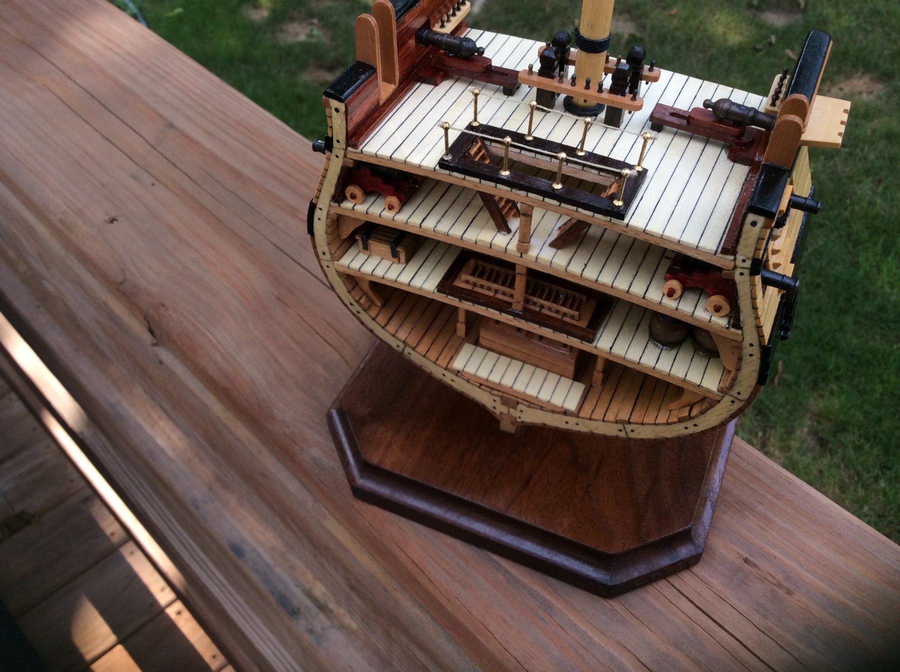
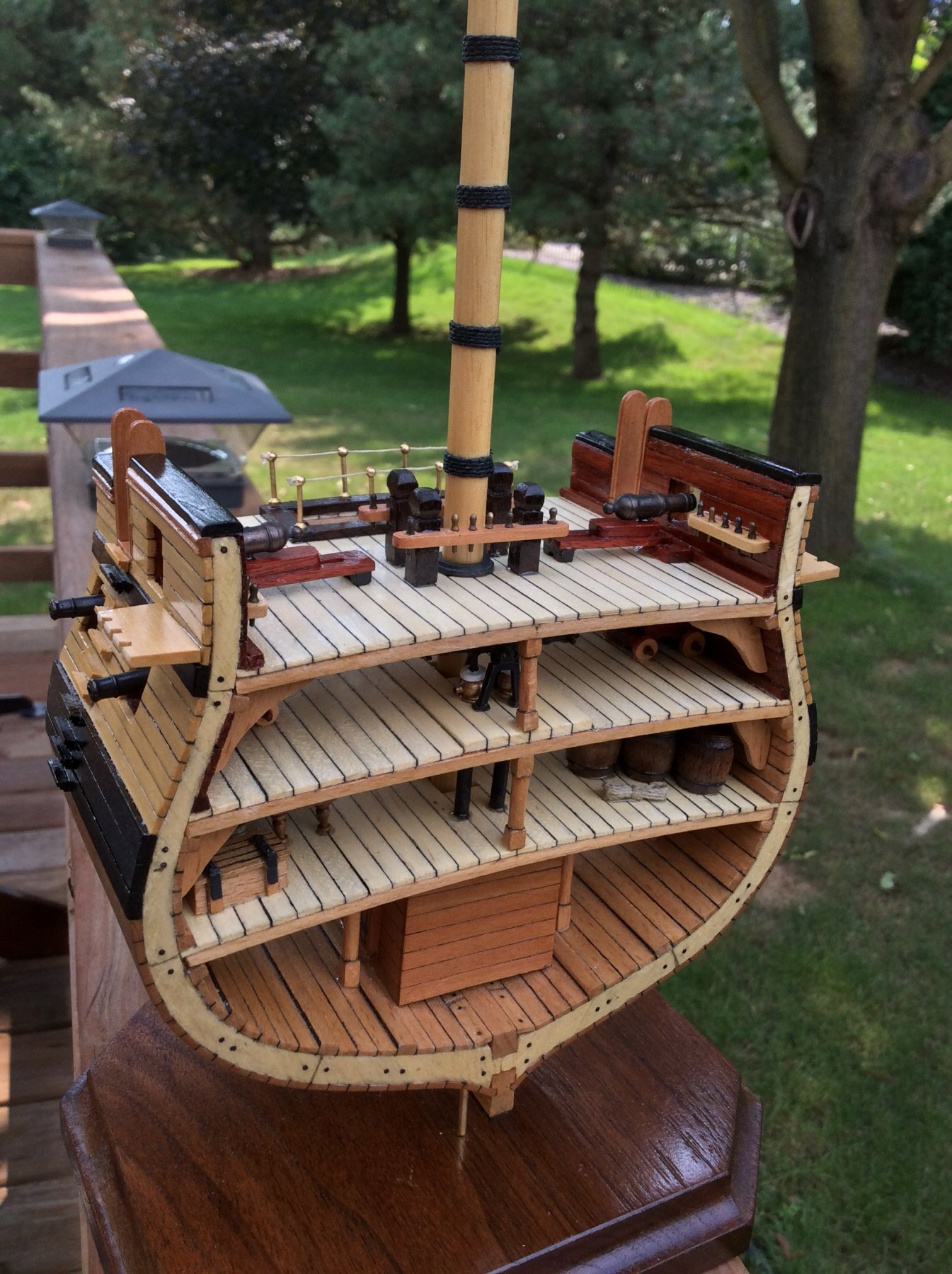
Almost done! I'm in the home stretch now. I finished the poly, installed the main mast bitts and glued the mast in place,
installed the brass stanchions for the guard rails on the ladder hatch and rigged the safety lines, and glued the carronades in place.
All that's left:
-mount the hammock netting stanchions.
-mount the gun port lids.
-Mount the deadeyes and chain plates and finish the channels


- David Lester, mort stoll, DCooper and 7 others
-
10
-
Great job, David! She looks great. I'm looking forward to following you Morgan build.
-
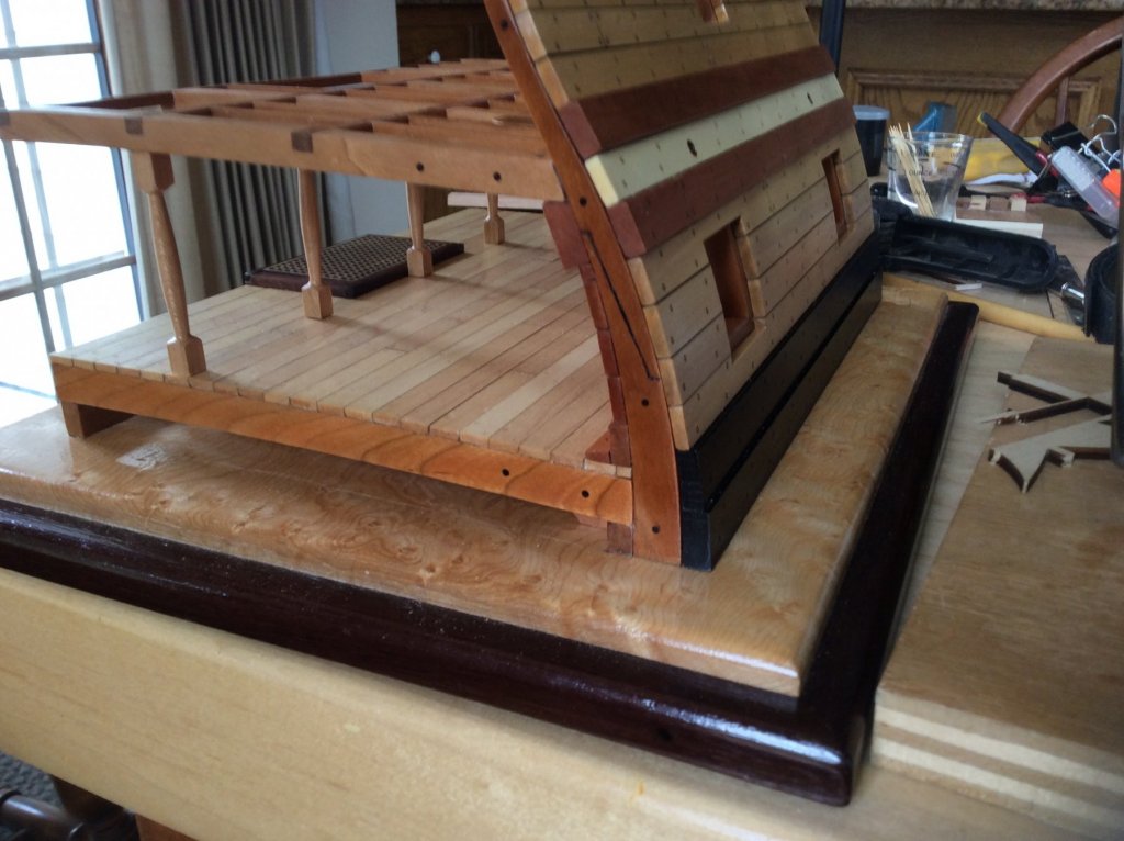
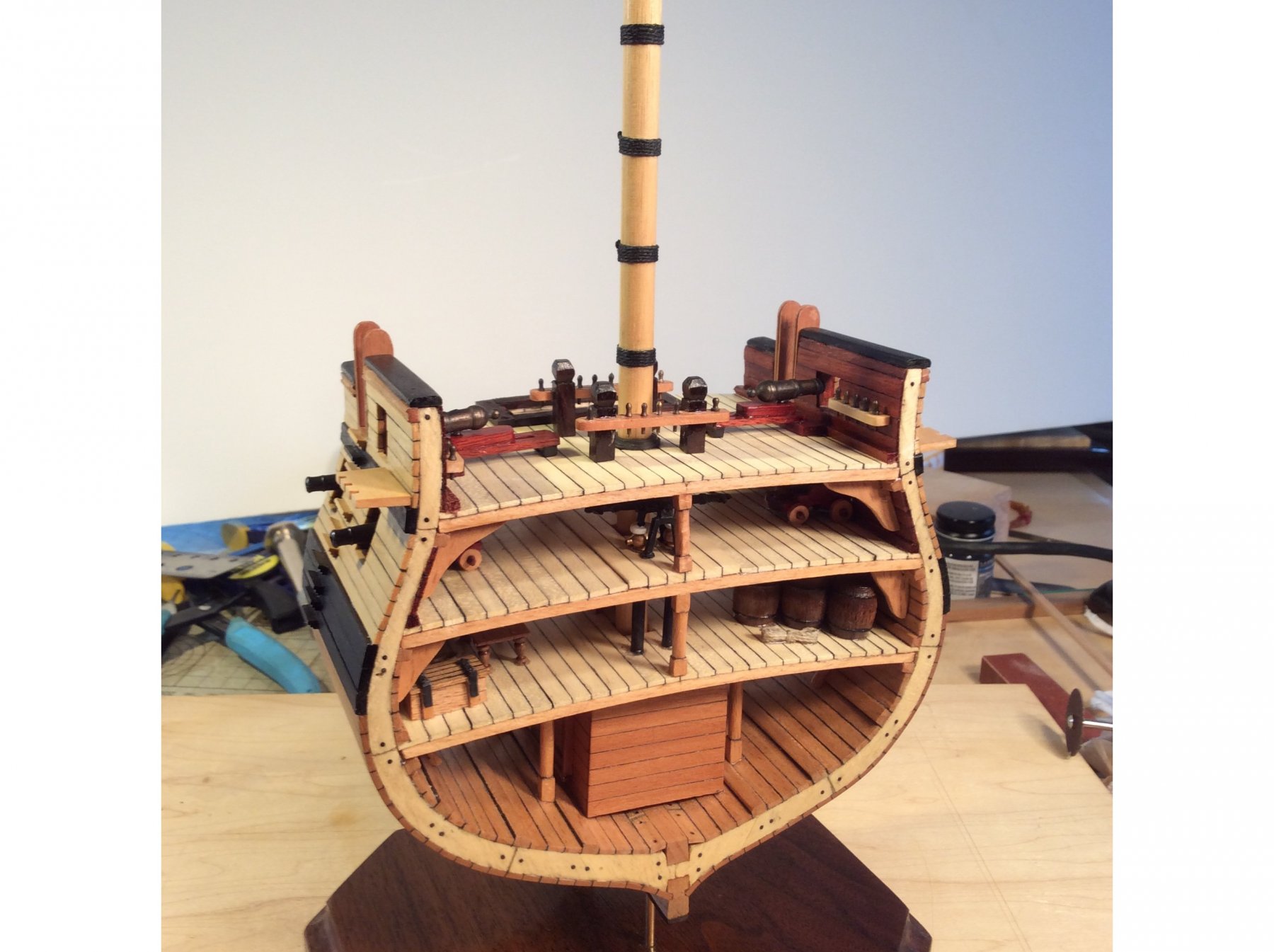
I had a nice 3/4" thick walnut cutoff in the shop. I cut it to an elongated octagon shape and routed a profile on the edges. I wiped on several coats of wiping poly. To mount the model a took a two pieces of brass rod, 1/16" diameter and epoxied them into two holes I drilled into the keel from the bottom. I the took 2 pieces of 1/16" I.D. brass tubing and mounted them in holes I drilled in the wood base. The brass rod fits inside the tubing and supports the model.
I added the two channels and belaying pin racks and started putting the final coats of poly on.
Remaining jobs:
-finish the poly.
-mount the deadeyes and chain plates.
-install the main mast bitts and glue the mast in place.
-install the brass stanchions for the guard rails on the ladder hatch.
-glue the carronades in place.
-mount the hammock netting stanchions.
-mount the gun port lids.

- rafine, Ryland Craze, Tim Curtis and 5 others
-
8
-
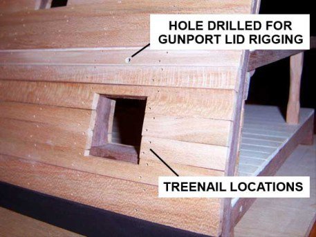
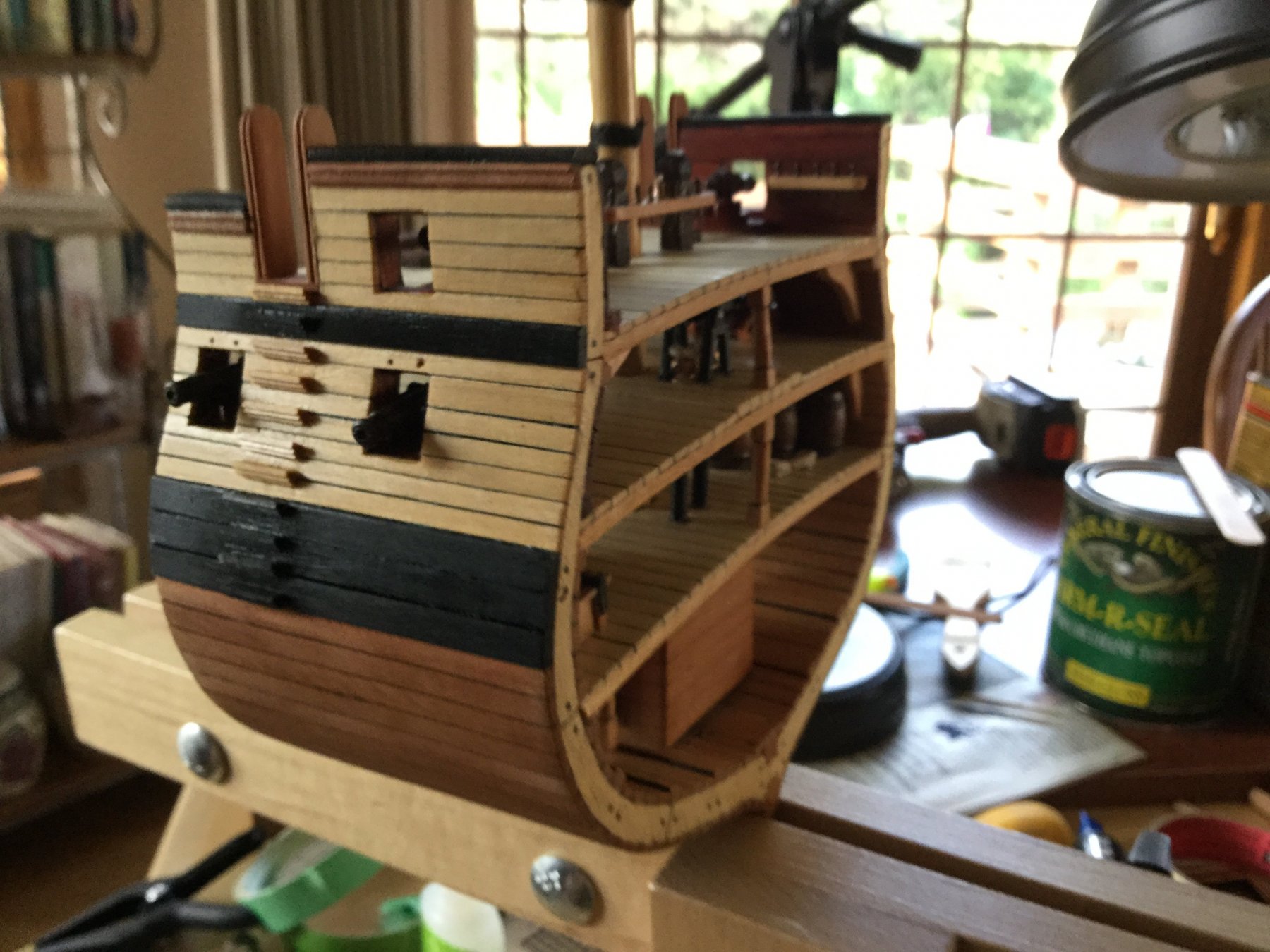
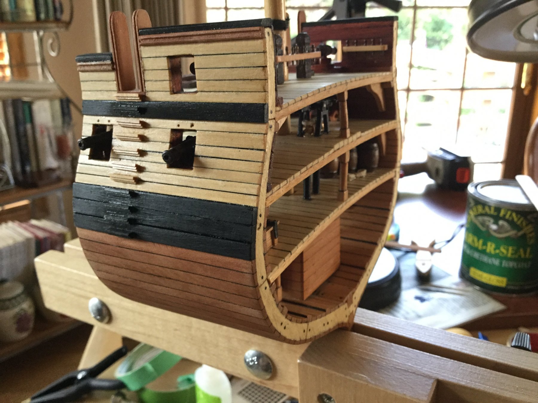
We were following the plans for treenail locations. The drawings were imported into CAD and used to guide the laser etching which created the treenails. I have seen the gun port planks handled both ways, on modern day as well as contemporary models. I personally prefer the diagonal pattern at the gun ports.
-
No! Since this is a cross section, it is as if one "cut out" a section of the ship. If the plank truly ended at the edge of the slice, then yes. the treenails should be above each other as they are on all the butt joints on the model. The planks actually continue on beyond the cross section, so the diagonal orientation is appropriate. It is how it would be on the whole model.
-
I built the clamp, Mark. Pretty easy and it works well. Here's a link: https://modelshipworld.com/index.php?/topic/12895-independence-1775-by-docblake-artesania-latina-516-scale/&page=3
-
-
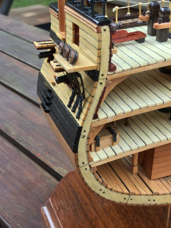
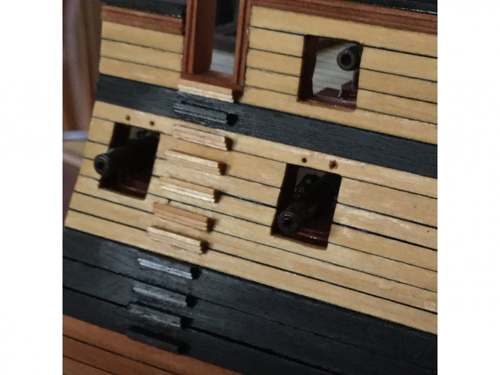
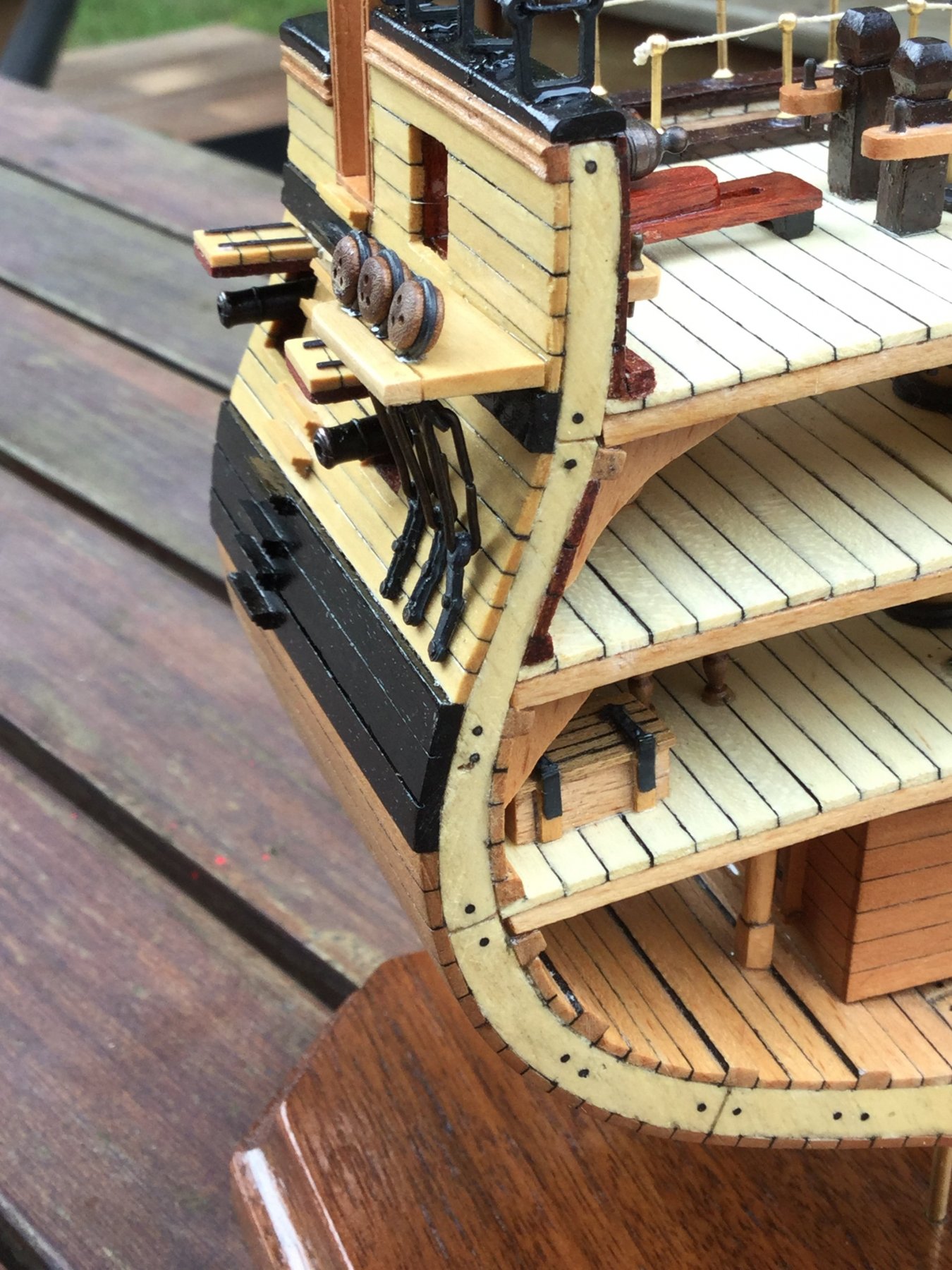
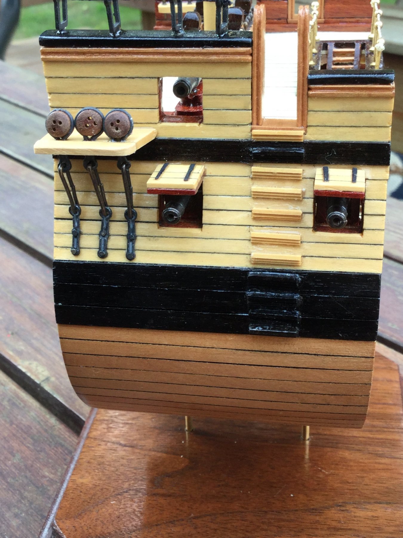
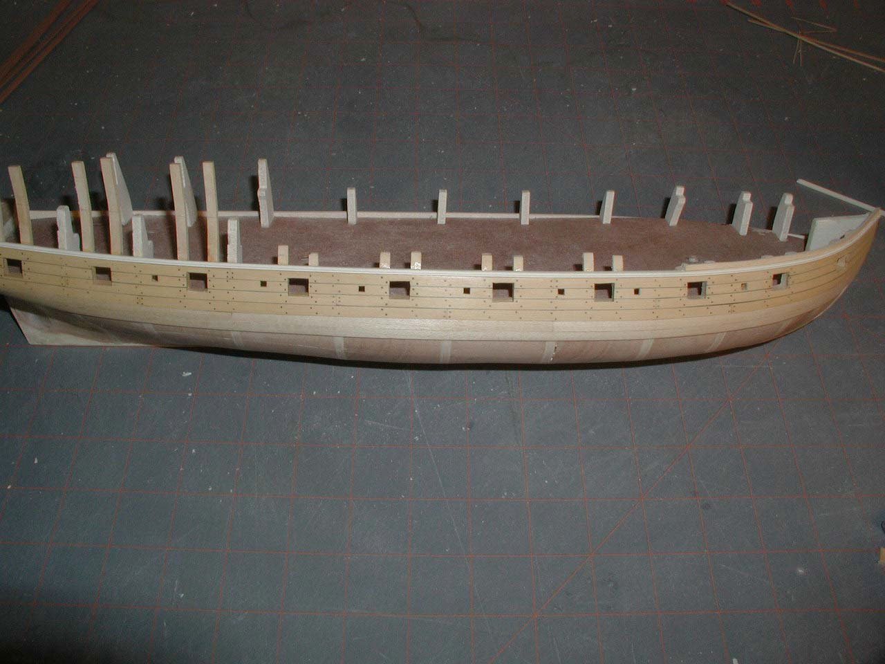
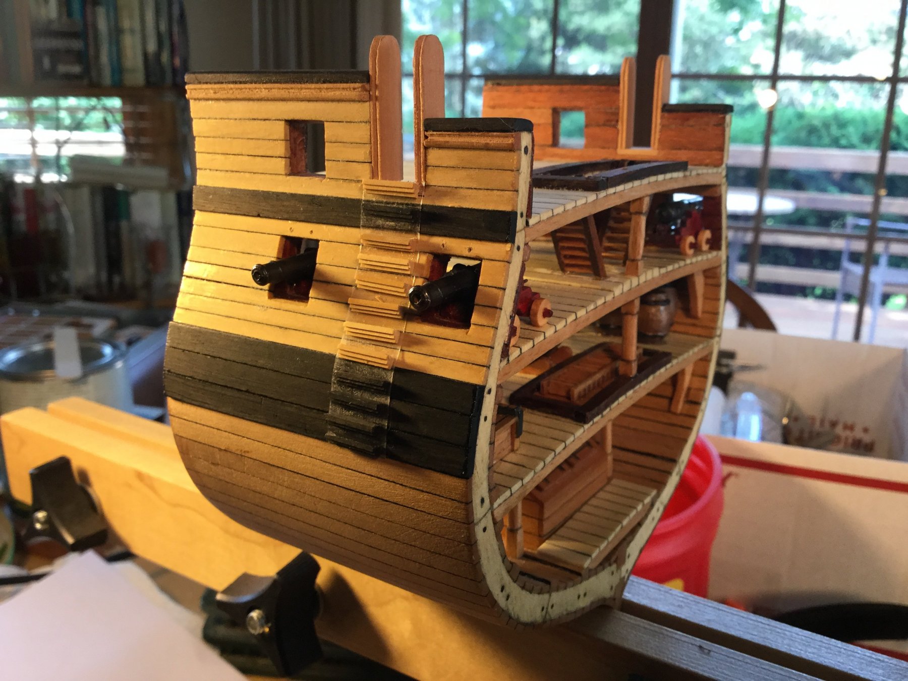
I finally got around to gluing the boarding steps to the hull. The first step was to draw a vertical line lightly in pencil as a guide so the steps line up one below the next. I laid out the pattern of the steps so that the spacing between steps is correct, using double sided tape. See the photo in my post above. I then started gluing the steps to match this layout on the opposite side. To glue I used two small drops of WeldBond and three tiny drops of gel CA. It worked well. In the photos you can also a fife rail with belaying pins an the bulwark, and the aft bit at the level of the main mast. The holes above the gun ports are to mount the lids with pins and glue. The channels and deadeyes are next.
I do have one dilemma! Most (but not all) British naval vessels had hammock netting attached to stanchions on the main rail. The stanchions are included in the kit , as is some white gauzy fabric to make the netting. I think it will look like crap. I'm thinking of mounting the stanchions and their ropes without adding the netting. What do you think?
-
BTW: The keel clamp the model is sitting in is one I designed and build myself. I used fancy plastic star knobs for all the carriage bolts, but if you use plain old thumb screws, you could build the whole thing for about $5 if you have some scrap hardwood laying around!


-
-
-
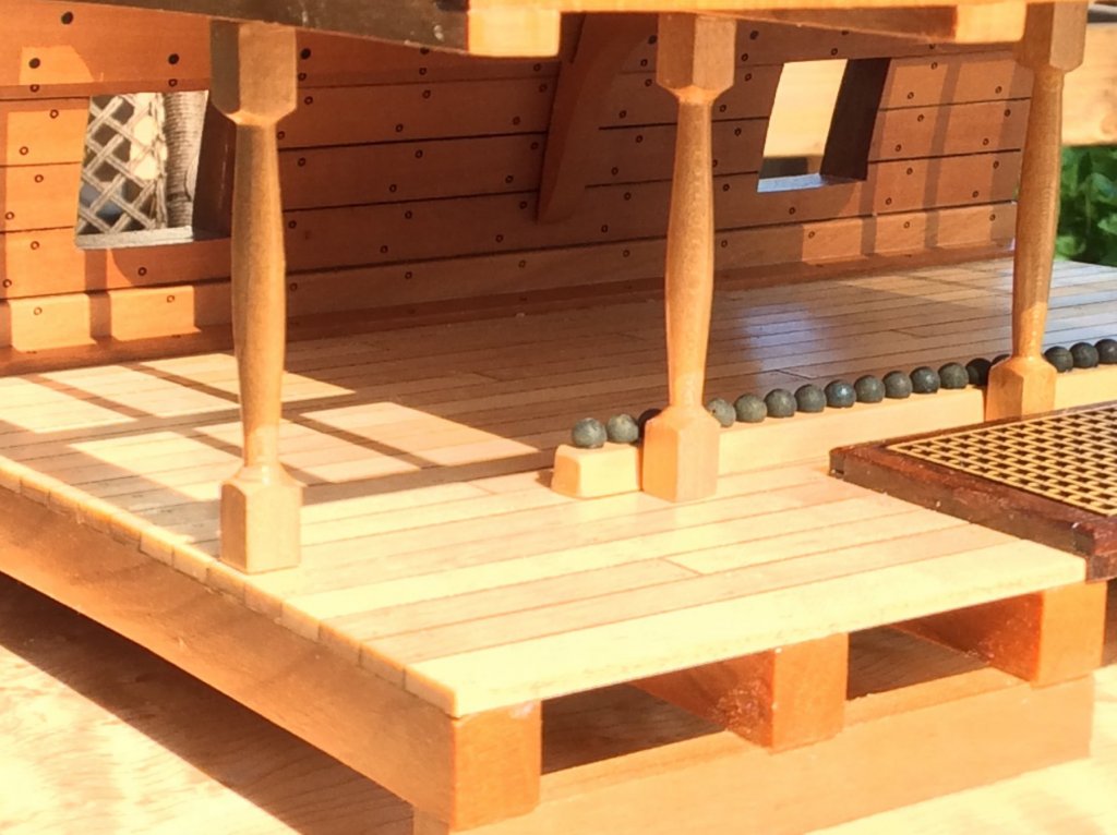
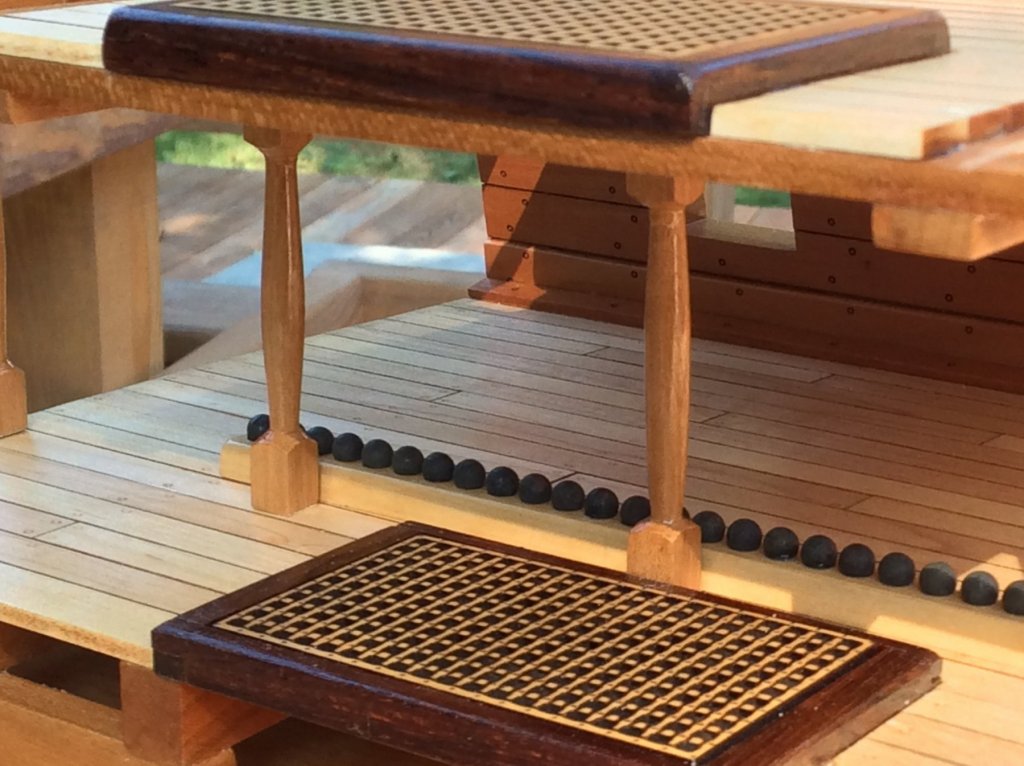
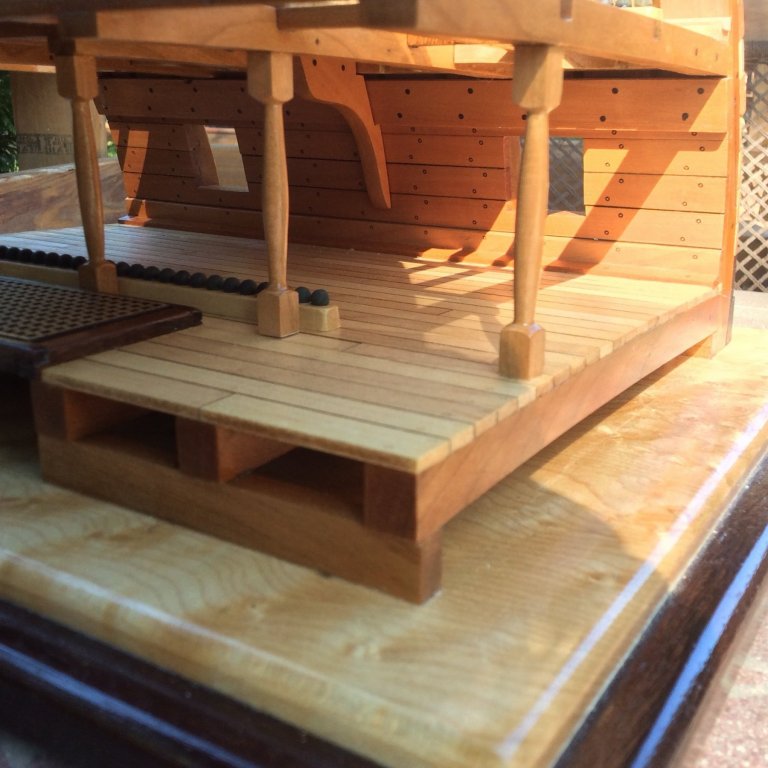
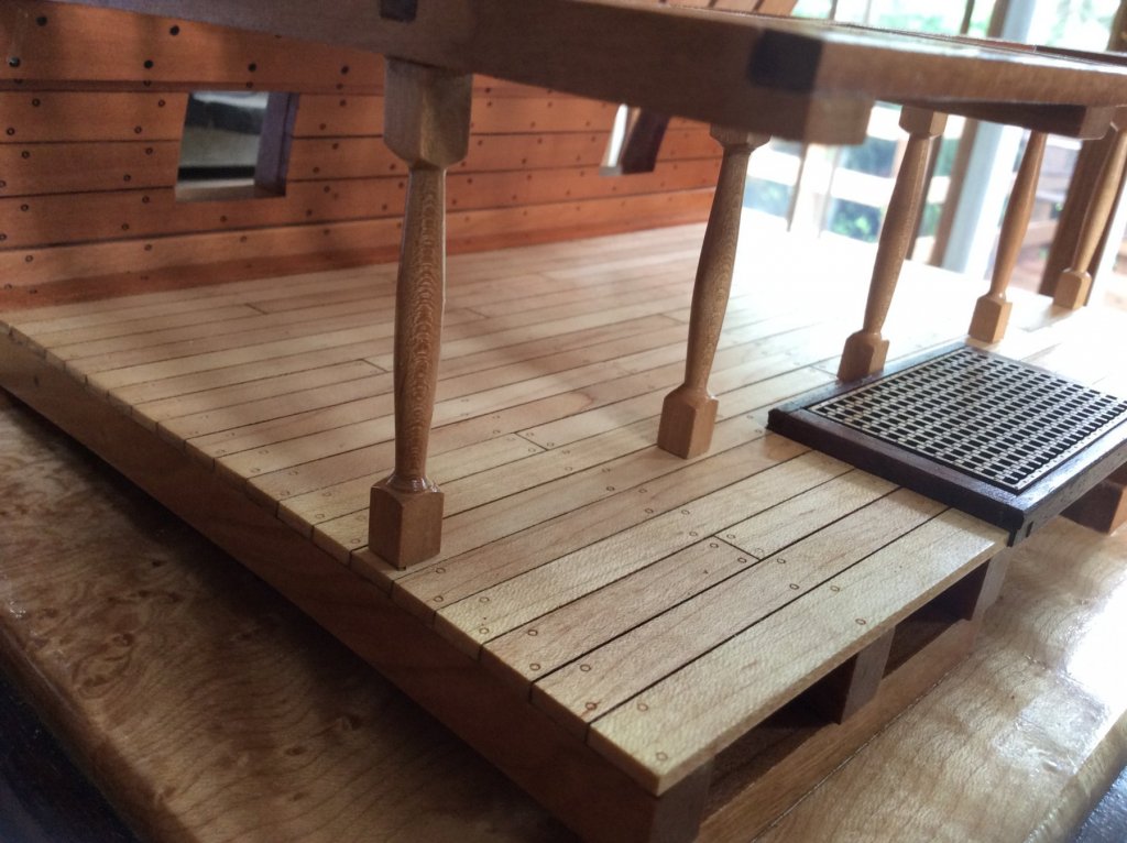
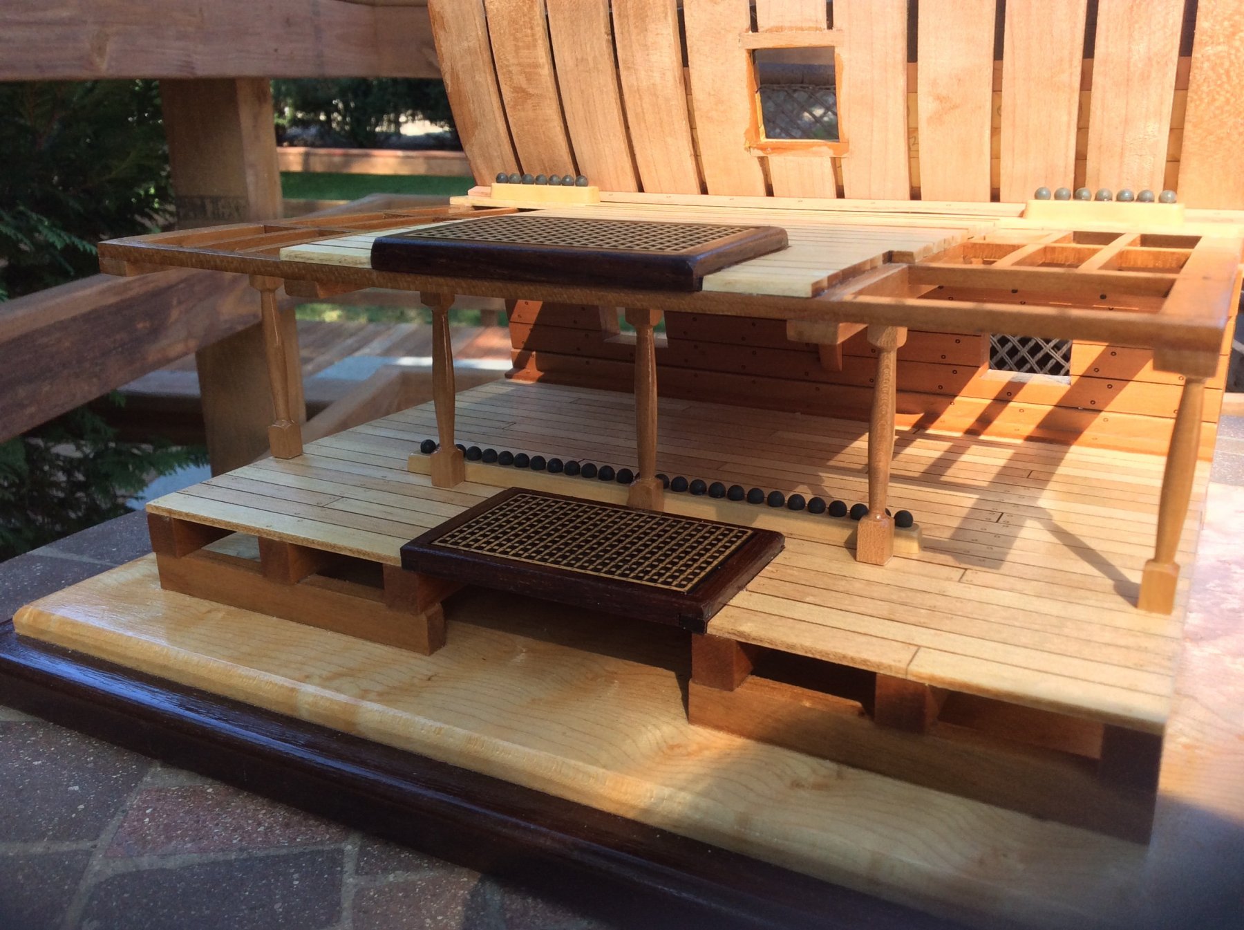
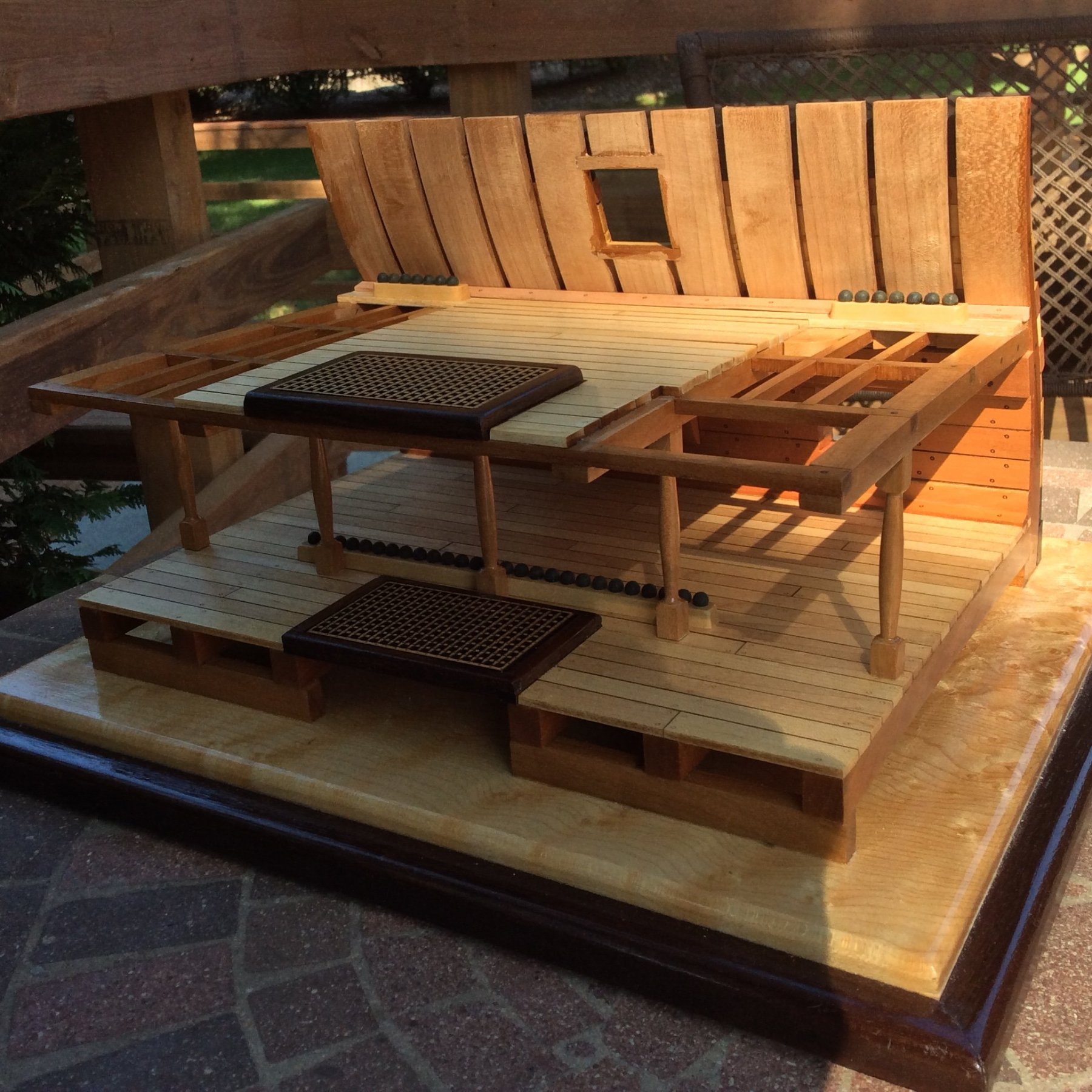
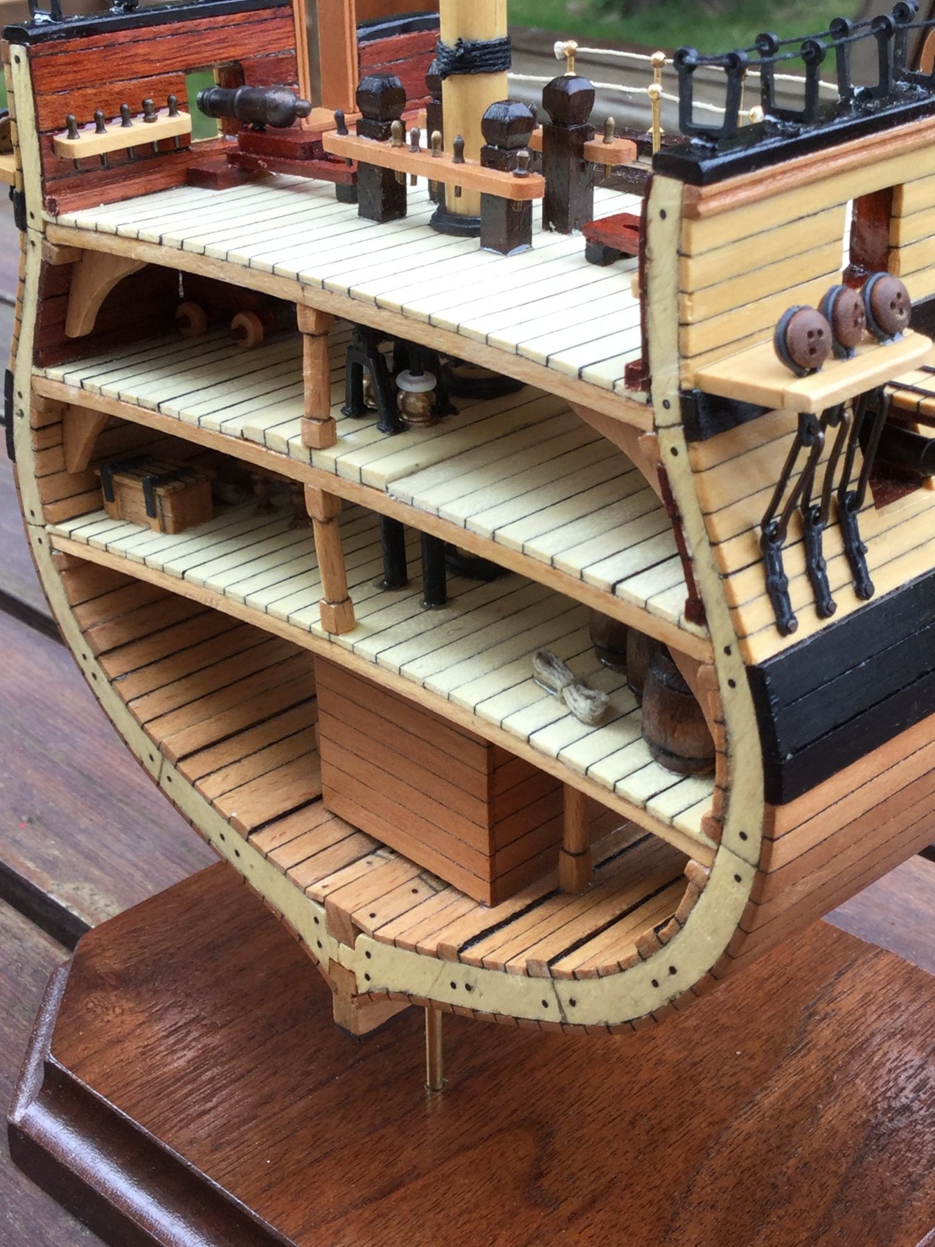
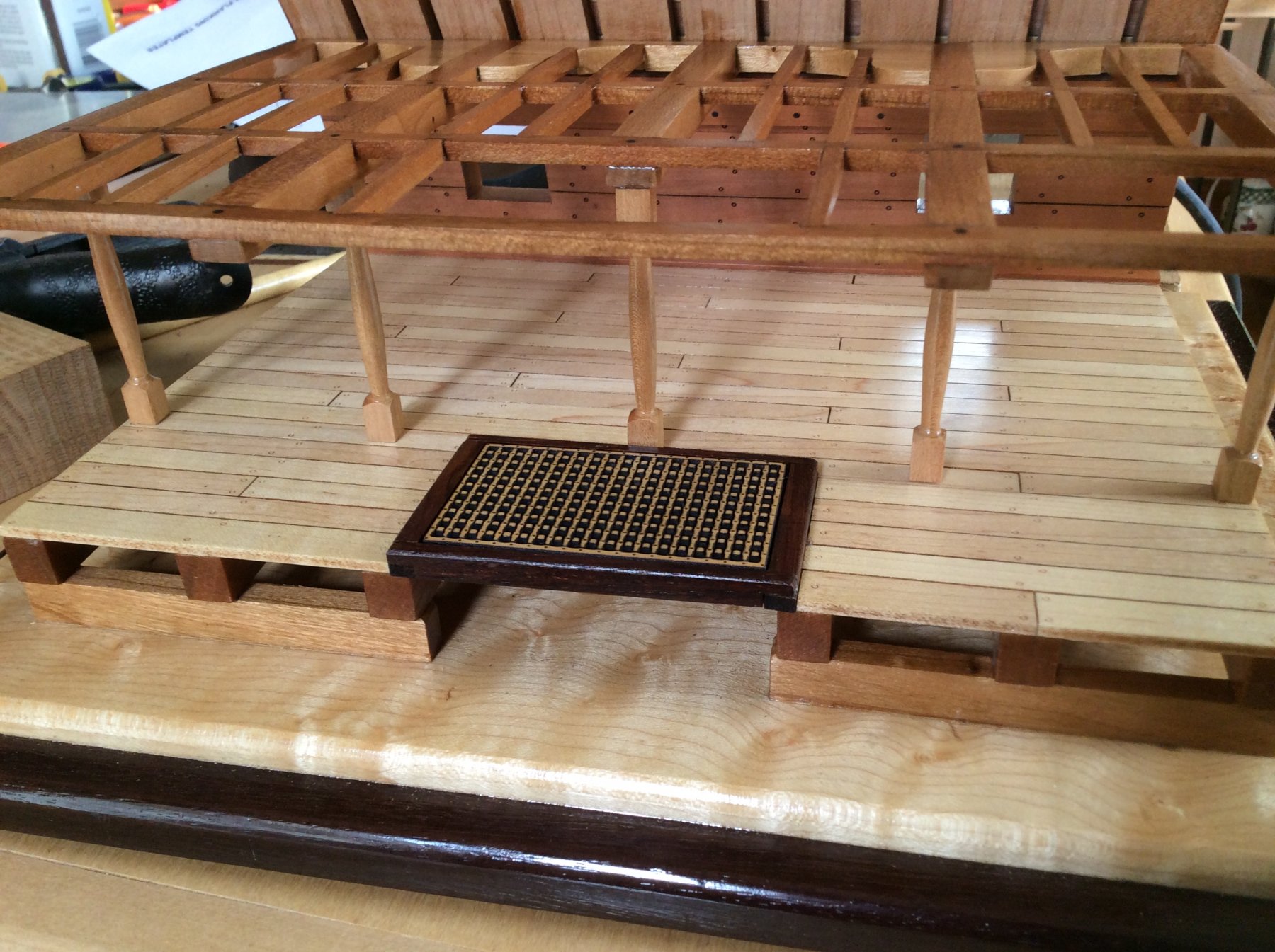
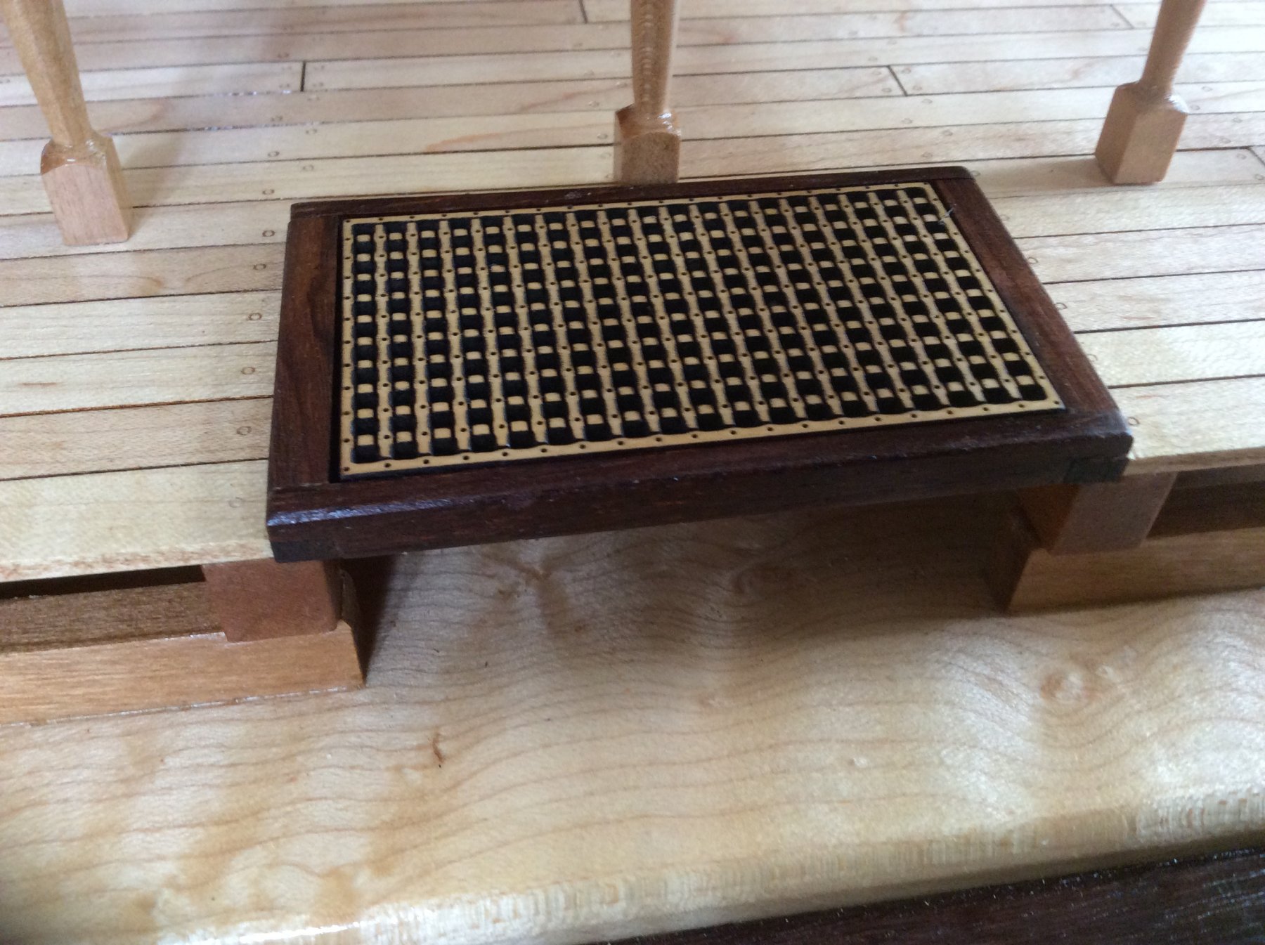
I wiped poly on all the parts after pinning and gluing the support columns to the deck beams. I used epoxy, and the joints are very strong. The upper deck/column assembly will simply be glued to the deck clamp and lower deck. The fit is perfect and no pinning is necessary.
The hatch grating is boxwood and laser cut. The coaming is rosewood with half lap joints at the corners. There is a small "shelf" under the coaming to support the grating. It just drops into place. Both have poly on them.


-
Beautiful job rigging those guns, Bob!
- Canute, Martin W, Old Collingwood and 2 others
-
5
-
Great job, David! The rigging turned out very very nicely.
-
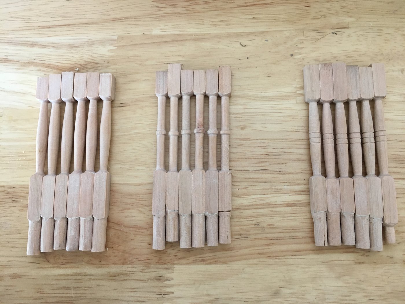
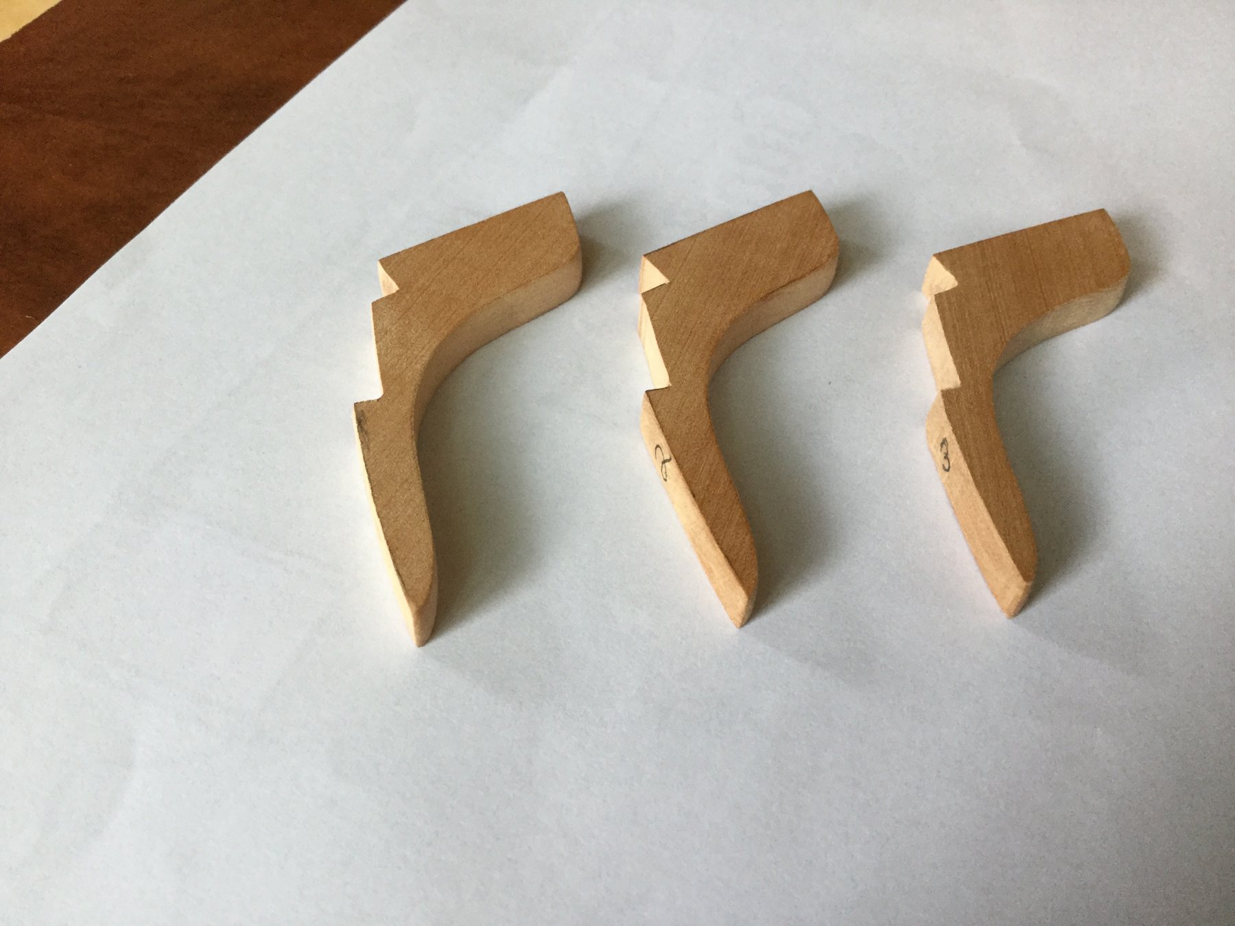
Don turned 6 support columns for each of us, and as it happened, we all chose a different design. The extra one is insurance against our propensity to screw things up! The first photo shows the three sets of blanks.
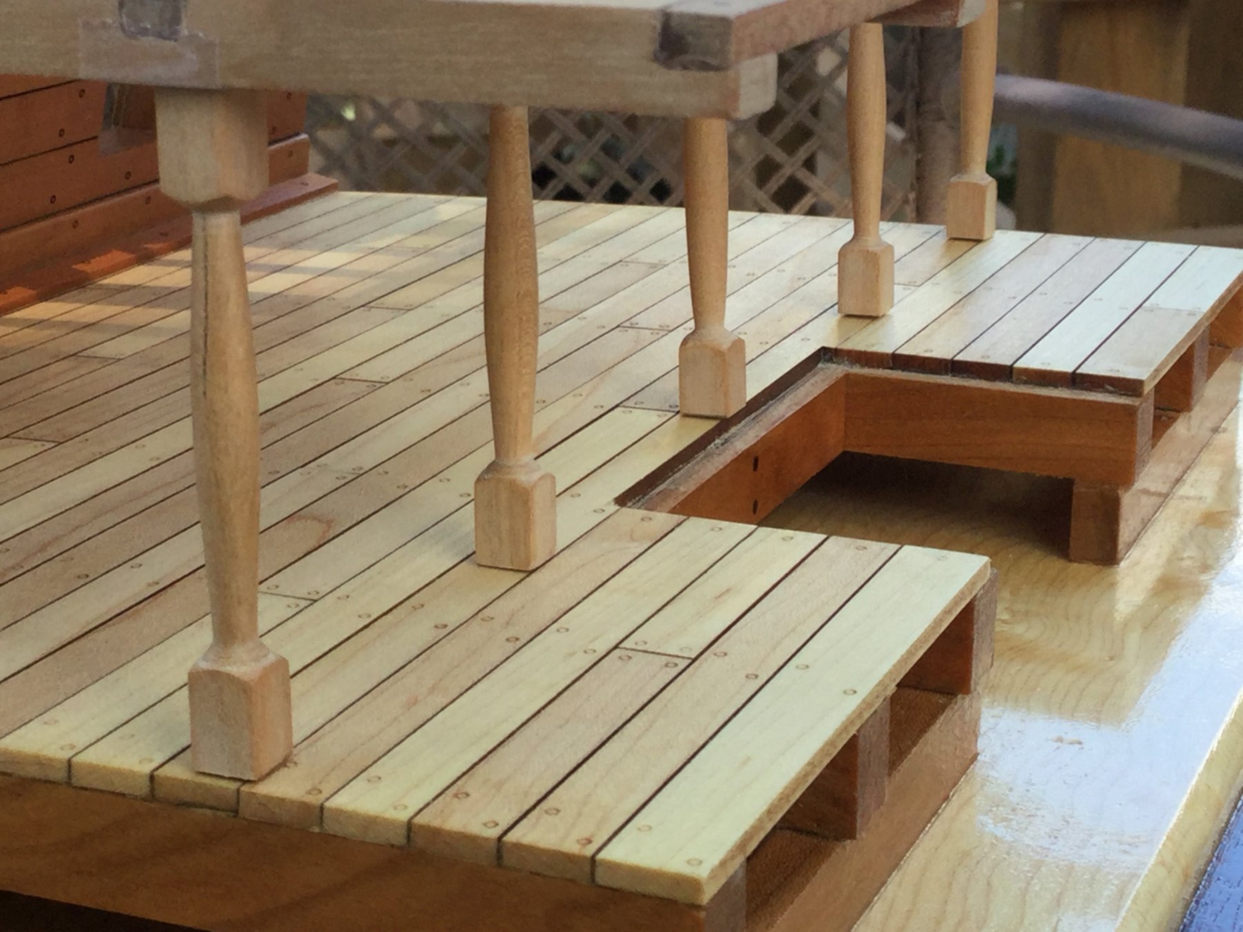
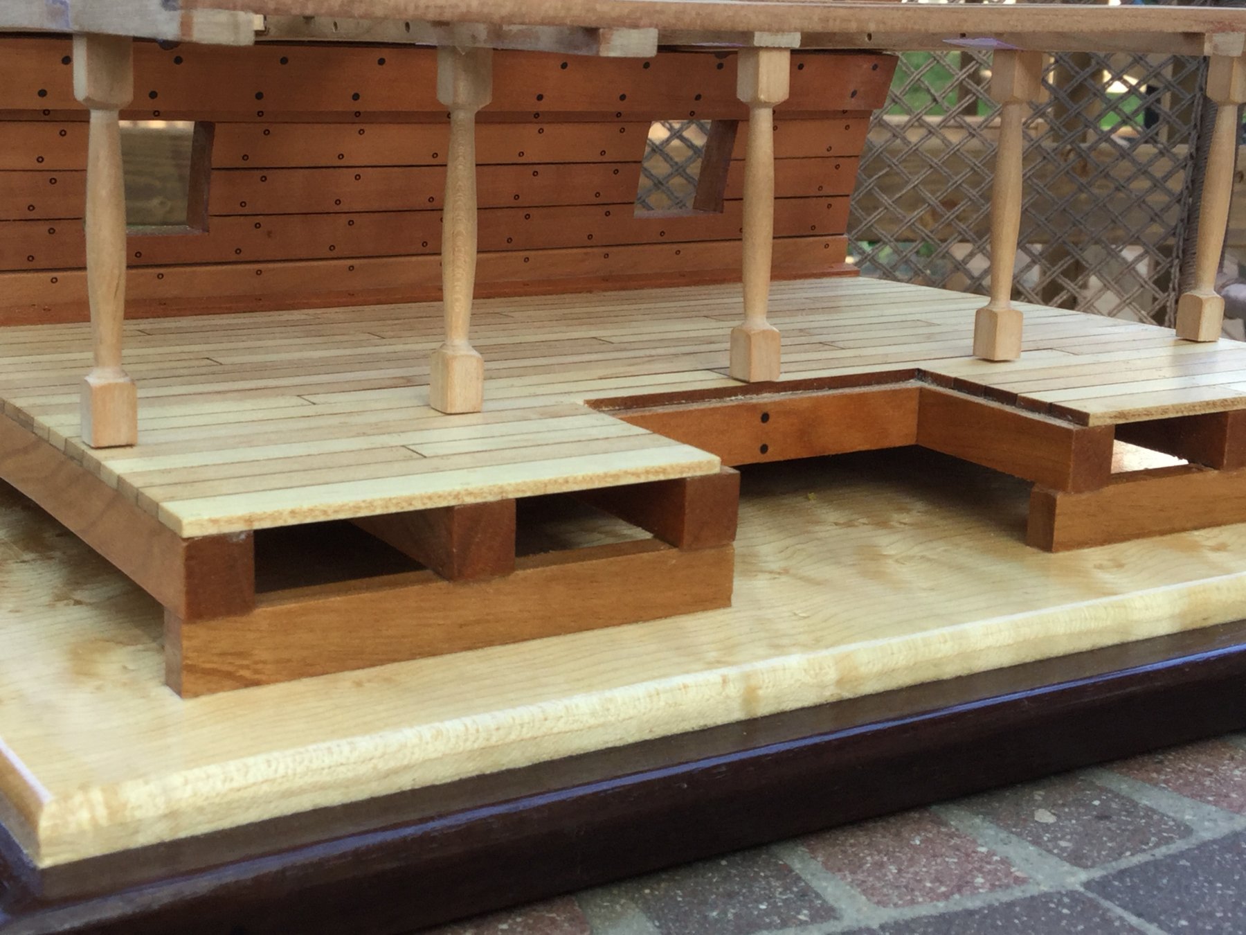
I cut mine slightly (1/32") long so I could fine tune the fit to any irregularities in the upper deck beams or lower deck surface. The dry fit worked out well. the columns were then numbered on the bottom so they go back in the right place. Each was trimmed/sanded so all 5 rested on the lower deck, and none were "suspended " in air!


-
Today I cut and custom fit the hanging knees. There are just three: one each at the two end deck beams and one at the center one. To fit them, they must bear against the hull planking and the deck beam, and the must be notched out for the lodging knees and the deck clamp. I made a template, traced the final result onto my hanging knee blanks, cut out the notches on my scroll saw, and final-fit them with a sanding stick and some files.

-
Awesome work! Well done.
- mtaylor, aviaamator and Canute
-
3
-
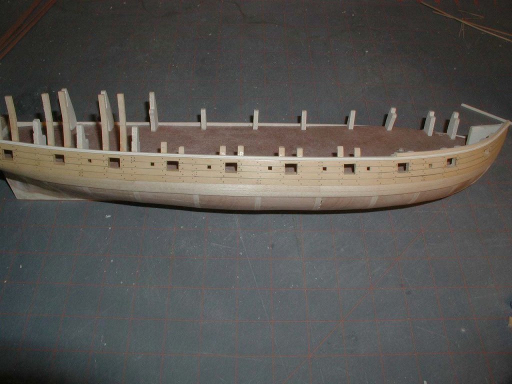
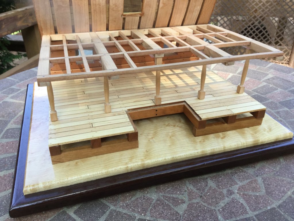
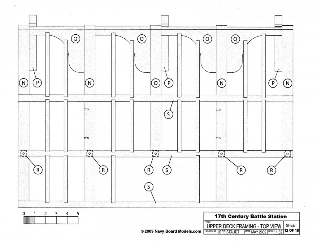
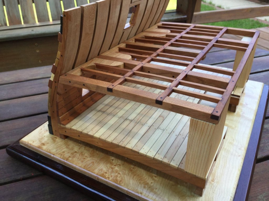
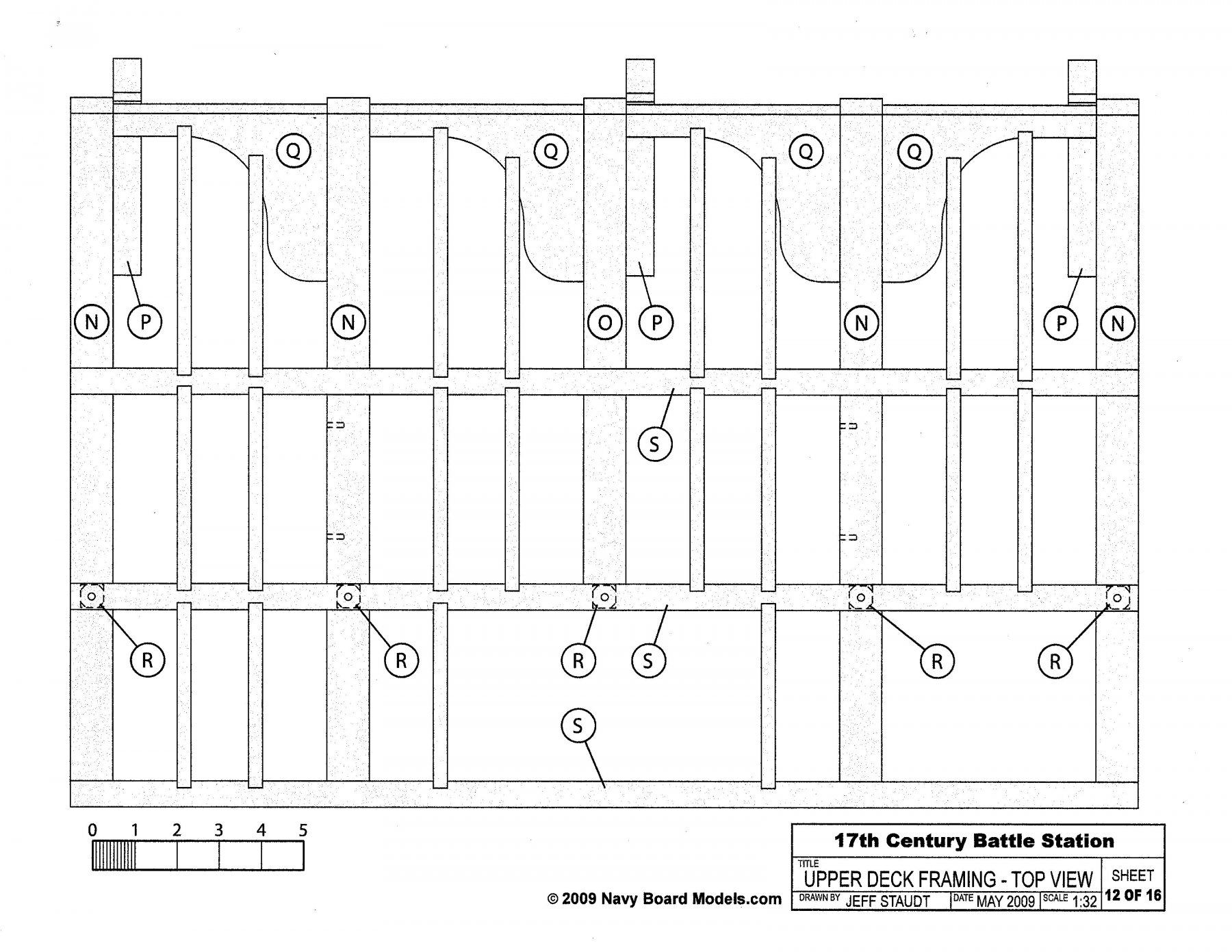
I spent yesterday finishing up the framing of the upper deck. the three of us had a lot of discussion as to the accuracy of the deck framing. In general English framing, each deck beam has a lodging knee and a hanging knee, and all the lodging knees face the same way until amidships, where the knees start facing the opposite direction. This corresponds to the point where the futtocks of the framing reverse, and the floors start facing the opposite direction. The main mast should be located near here also. We came to the conclusion that the framing of the upper deck on this model was stylized, and also altered to accommodate the two lower gun ports. One of us objected to the lack of symmetry, and proposed the pattern you see on the photos. I followed suit. It really doesn't make any difference since the center of the upper deck will be planked over. I've included the plan sheet for the upper deck framing with the other photos.

-
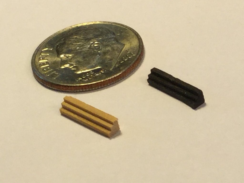
I've been busy with other projects, but it's time to put this one to bed! I've been procrastinating because I need to add the boarding stairs and I think this is going to be a really stressful, difficult part of the build. The first step is to cut the individual treads from ebony and boxwood. The treads are 2mm X 2mm X 10mm, which is very small! I first cut the tread profile on my Byrnes saw, then cut out each individual tread. Here's a shot of the treads stuck to the side of the hull with my go-to temporary adhesive : double-sided tape. Placement of the treads is really finicky. I think I'll take a few days to work up the courage to start gluing them in place!

-


Royal Navy Ship of the Line Cross-Section by DocBlake - FINISHED - based on Mamoli's "Constitution" - 1:93 scale
in - Kit build logs for subjects built from 1751 - 1800
Posted
Thanks guys, and for all the “likes”! Not sure what is next.