HOLIDAY DONATION DRIVE - SUPPORT MSW - DO YOUR PART TO KEEP THIS GREAT FORUM GOING! (Only 36 donations so far out of 49,000 members - C'mon guys!)
×


Snug Harbor Johnny
-
Posts
1,466 -
Joined
-
Last visited
Content Type
Profiles
Forums
Gallery
Events
Everything posted by Snug Harbor Johnny
-
 I tip my hat top this well-run and reliable forum. Indeed, down time is rare ... and most of have either builds to work on or books to read on those rare occasions.
 -
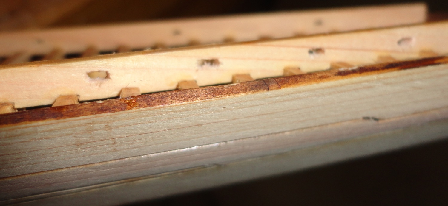
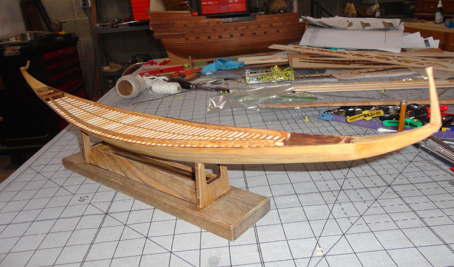
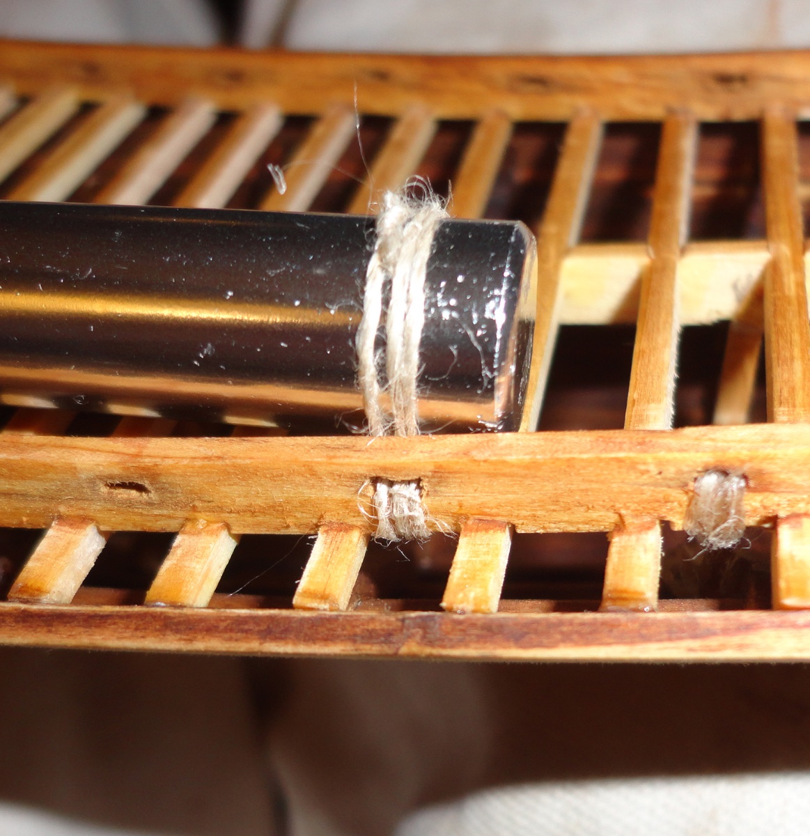
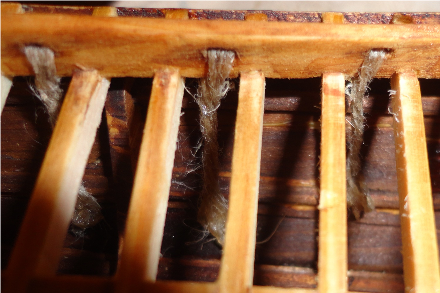
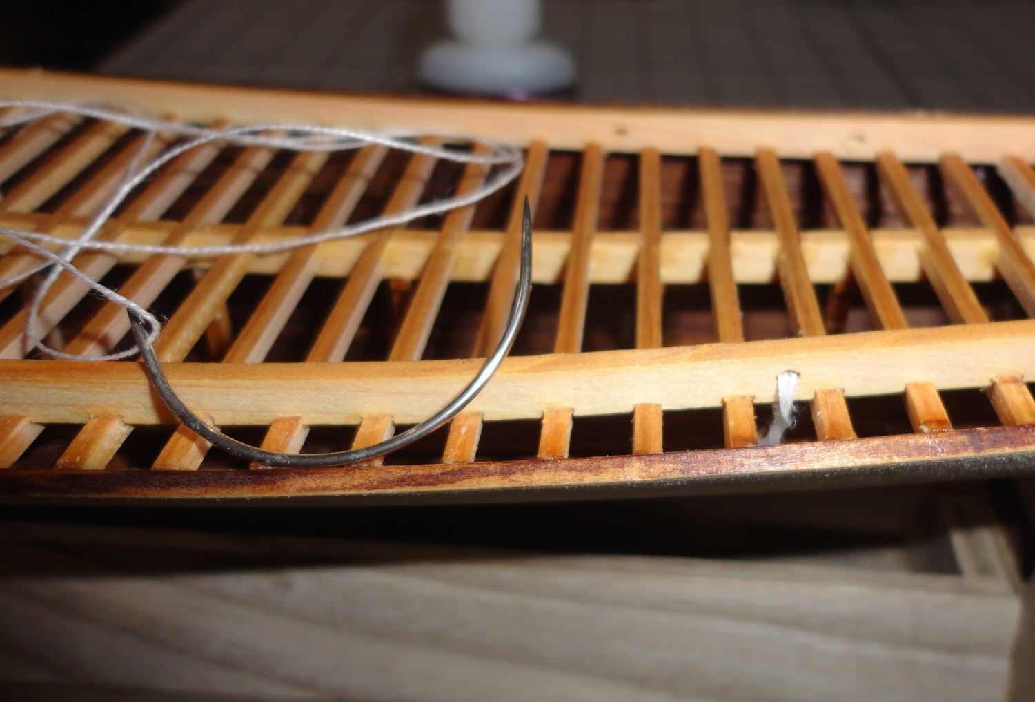
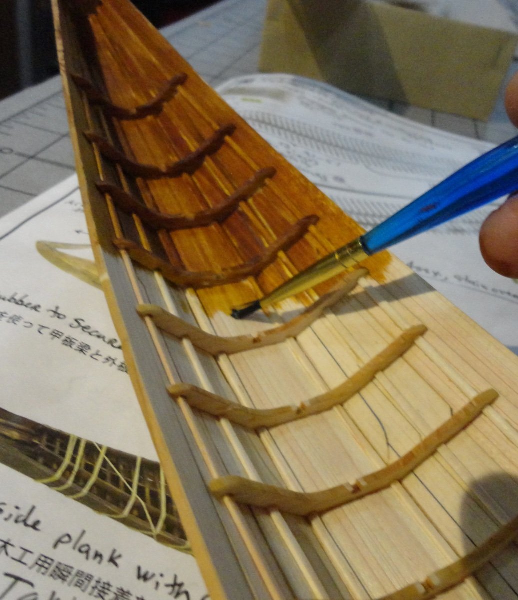
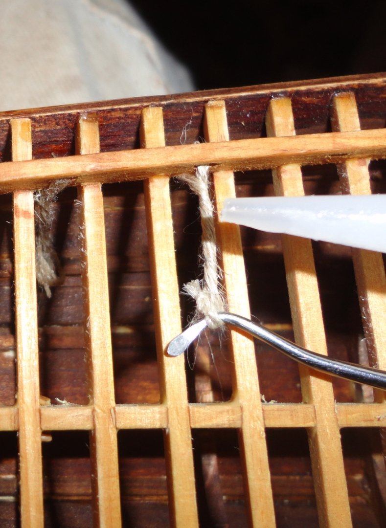
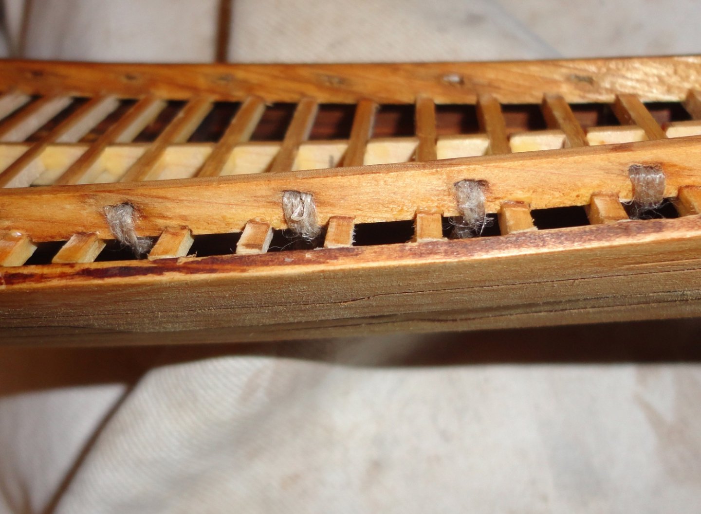
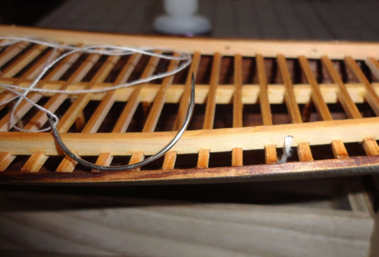
Since the side rail tie-downs are so clearly seen on the original, I went ahead with their installation even at this stage. Obviously I could've made neater slots on the rails when they were flat. There are some irregularities in this 'seat of the pants' backfill method - but close-ups emphasize defects, and are not noticed so much when observing in-person. My camera skills are rough, and the focus is not always sharp - but often I'm holding the camera with one hand while holding a tool in the other with the model balanced in some way. Step one was to make divots ('spot drill') with a miniature square file so the #60 drill would be less likely to 'walk'. Then I drilled the pair of holes. Next was to cut parallel lines with an X-Acto between the tops of the holes, so the chunk in the middle could be winkled out. There are 25 slots on each side to make. The kit maker could have laser cut these precisely - but that would have added effort to the kit in general (putting in the side rail tie-downs). A light brown color was applied to the hull (it looks a little darker in person) and looks OK to me in-person. Many models seen have light to medium exteriors - like relatively fresh heartwood cedar. The dark tea-stain suggested by the kit seems too dark, but perhaps that is because the 4,000 year old wood is on the dark side. The stand was given a coat of amber shellac and lightly sanded. The main deck was trimmed on the edges as needed with a lot angle plane and the edge was lightly sanded during trial fitting between the side rails (to allow a slight clearance for the ropes to be installed.) A large X-Acto handle was used to sew some 2-ply linen thread (made by a crafter I saw at a demo) with a curved needle as previously shown. There is some 'fuzz' to this stuff that really shows in the close ups. Hmmmm, its time I set-up the Syren Rope Rocket and try and make better miniature rope to use on the other side. On the other hand, it doesn't look bad when looking at the project - which is also true when seeing small defects in close-ups on other builds. Still, the better one can do, the better the model. A dental tool twisted the wrap on the other side, and I put a little CA to 'lock' this twist in place. Remember, the rope would have been far easier to do BEFORE gluing the deck support system into the hull. Well, building is a little like a 'chess game' of sorts - one has to think a few moves ahead before 'painting oneself into a corner'. The dental tool was used to pull the twist beneath the deck beams for attachment to the hull with a little more CA. From the outside (the inside will be covered by decking and won't be visible) it doesn't look too bad. Well, mates, I'll send some time learning to make my own rope for the other side. Lessons learned that will benefit other work down the line. I said at the outside that this was a 'palette cleanser' project ... one that can be accomplished in FAR less time than doing something like the Victory. I never 'time' myself on how long is spent doing any project - partly because I work slowly and could never 'make a living' at it. My guess of the time spent so far on Khufu's ship is something like 25 hours - not counting drying time when I can be off doing something else ... like Admiralty projects.


- 63 replies
-
- 7
-

-

-
- Finished
- Khufus Solar Boat
- (and 1 more)
-
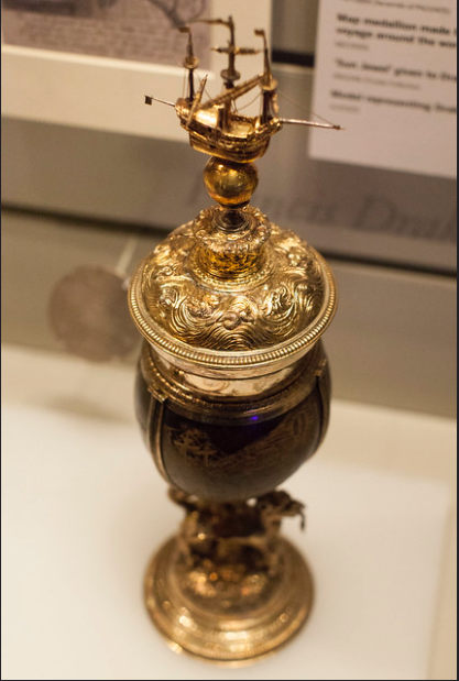
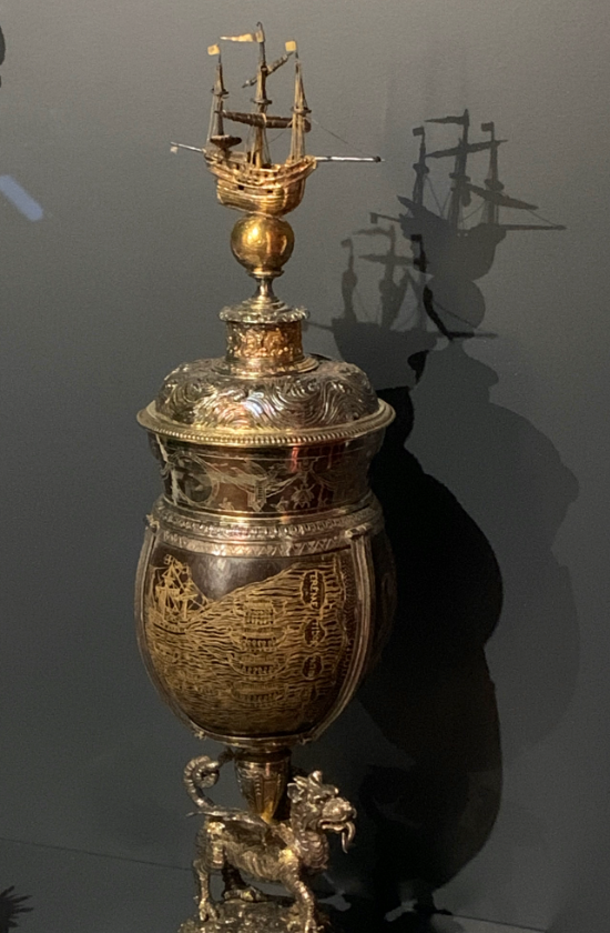
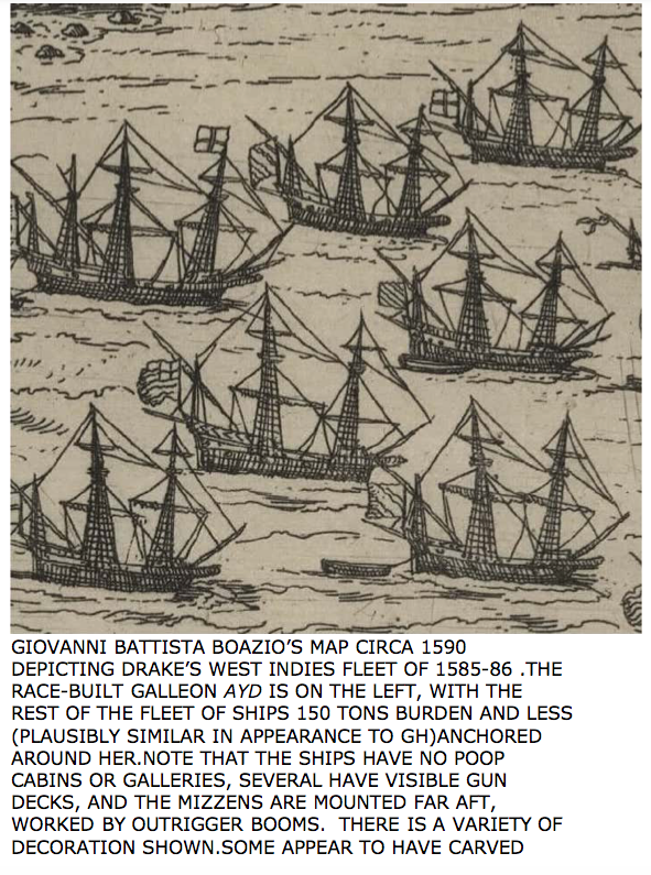
Don't overlook the silver miniature of the GH commissioned by Queen Elizabeth and presented to Drake once atop the mounted coconut (Drake gave to Elizabeth after his circumnavigation) she had engraved and made into a silver-mounted cup. The Queen KNEW what the GH looked like, knighted Drake on the deck of the GH and had the ship moored on the Thames as the first 'museum ship' ... So the silver miniature is both contemporary to the GH and must have (with a jeweler's simplifications) had the key features of the vessel. Per the photo below, one can just see openings on the weather deck (no guns at this scale, but they'd have gone there), stern pole for managing the mizzen lateen (mizzen mast towards the stern), sail configuration (sans yards on fore mast and bowsprit - can't say why) and the absence of a 'captain's walk' around the stern. From another angle. Note the engraving of the GH (consistent with he silver miniature) being towed by native canoes at a Pacific isle. A contemporary depiction of Drake's 'Caribbean Fleet' And there are the depositions of DiSilva (one of them to the Inquisition - were his life and soul depended on his truthfulness), where the expert Portuguese navigator (a 'guest' of Drake from the Caribbean, around the Horn and to the West coast of Mexico) who states that the GH was 220 (Old Portuguese) tons. This works out to 175 contemporary tons. The length on deck of the GH replica moored on the Thames would be about right, but the builder's target of 150 tons kept the beam too narrow. Instability forced the addition of 'side bulges' (thereafter the ship was stable and sailed the oceans of the world) that brought the beam (if originally built that wide) to a size appropriate for about 175 tons (220 Old Portuguese tons). The beam on the weather deck (had the build lines conformed to the wider beam at the waterline ) would then have been wide enough for guns on the weather deck with allowance for recoil (25 feet instead of the 19 as built. BTW, the gun deck below the weather deck on the replica ship is 25 feet). DiSilva also noted that the broadside gunnery was 7 per side (5 main cannon per side plus 2 lesser guns per side, most likely on the quarterdeck as seen in contemporary illustrations) plus 2 stern guns and two at the bow. 2 guns pointing directly astern (one each side of the sternpost) are seen in almost all contemporary illustrations. It is not known whether the two bow guns were on the forecastle deck (for greater range) or mounted towards the bow on the gun deck at something like a 45 degree angle ... take your pick.
-
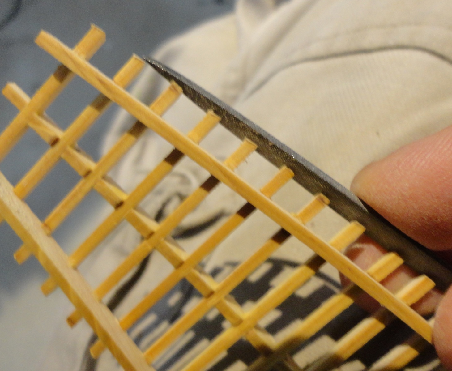
On second examination, it may be a thread lattice ... but how this was done (if thread was used) would be nice to see. A darker grey (if thread) might simulate lead cames used on such windows (same as used for stained glass windows).
-
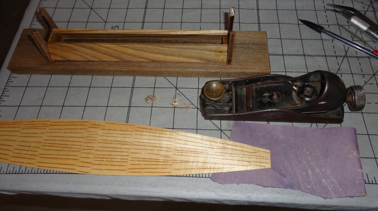
There are a number of beading tools that come in handy and are not expensive. After seeing the Admiral's set of beadwork tools, I got a few for myself and includes the above flush cutter ... works very well. Johnny
-
'Nice job on the ship's boats, mate ... about as good as can be done with the materials provided in the kit. I have the same kit awaiting build (there are two builds in progress that must be completed first) and have watched the first posted build log (by Hake Zou) through completion - and will now follow yours. The idea is to learn as much from others as I can from my own research before embarking on the venture. I added a few comments on the review of the kit (in the Review section of the forum) on likely ideas to improve the model without adding too much expense or deviation from what is a decent intermediate kit. Hake did a few, and has some excellent tips to do that will save trouble as you go further into the build. One idea I got from Rob's Glory of the Seas log concerned pre-rigging masts before finally gluing them into the hull, and that would be if one choose to install a circular pin rail near the bottom of the Endurance's masts and adding extra belaying pins (instead of relying on deck eyes as suggested by the kit). Hake did make sure his deck eyes were installed with a bent end under the decking before gluing the planked deck down - that way they could not pull out at a most inconvenient time later. Ropes (of sufficient length) were pre-attached to these eyes and pulled up for use later (rigging from the 'bottom up'), since having to tie them off from above offers substantial challenges if put off 'til later. But if circular pin rails are installed on the masts (this is also true to the original), then a lot of spar rigging can be done separate from the ship (like Rob did for the Glory) since it can be tied-off on the pin rail before installing the mast. Just a thought. Another opportunity is to create space beneath the forecastle deck (as per the original) by modifying the appropriate bulkhead and extending the decking beneath the forecastle deck. The provided sails (while adequate) could simply be duplicated in lighter material and they would look better. There are many railings, to be sure, and I went to the expense of getting 3-D stanchions from the aftermarket. Yet I may save them for another project I want to do at some point, and likely will make a mock-up jig for the various railing sections to mount the PE stanchions provided in the kit. Then brass wire can be threaded through and bent as needed before soldering in place with either a very fine propane nozzle on a mini torch or a decent soldering iron plus a touch of fine, rosin-core electrical solder. One used to get this at Radio Shack (I have a lifetime supply), but there must be other sources. Once cooled, the soldering point will have become 3-D and the railings should look much better than rope railings (after painting). Using metal chainplate (rather than pinned rigging rope per the kit) would be a plus (one can bend one's own wire), and perhaps slightly smaller (darker) deadeyes that would be closer to scale. Making rope or buying scale rope (from Siren Ships or Ropes of Scale) could be another plus, as it looks much better and has very little 'fuzz'. Better blocks are optional, as are better belaying pins. Whatever you choose to do, have fun doing it! Johnny
-
Rob, I was antiquing with the Admiral recently and came by a turn-of-the-century clothes wringer ... just the sort that can be used in your ingenious method of embossing copper strips for ship hulls below the water line (shown in detail in your Great Republic log). It had clamps for attaching to most table edges, a wooden frame with adjustable pressure leaf springs and the rollers were in good shape. The price was $125 - which I thought reasonable ... but as I was examining the wringer closely, the Admiral thought I didn't need anything like that. Whatever, these things are not 'fast movers' ...
-
'Looks to me (after scrolling up for the close shot of the windows) that a diagonal grid was scratched onto the surface of the clear plastic material - presumably prior to cutting the window to size from the scribed stock. One could apply black (or dark grey) color into the scribing with a fine tipped 'Micron' marker (from Pigma) - available at many craft stores.
-
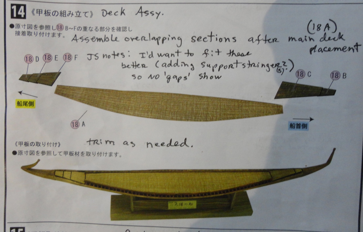
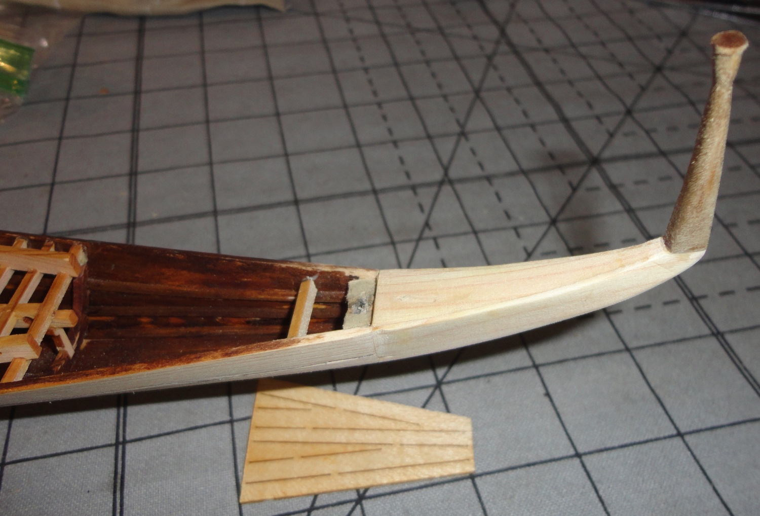
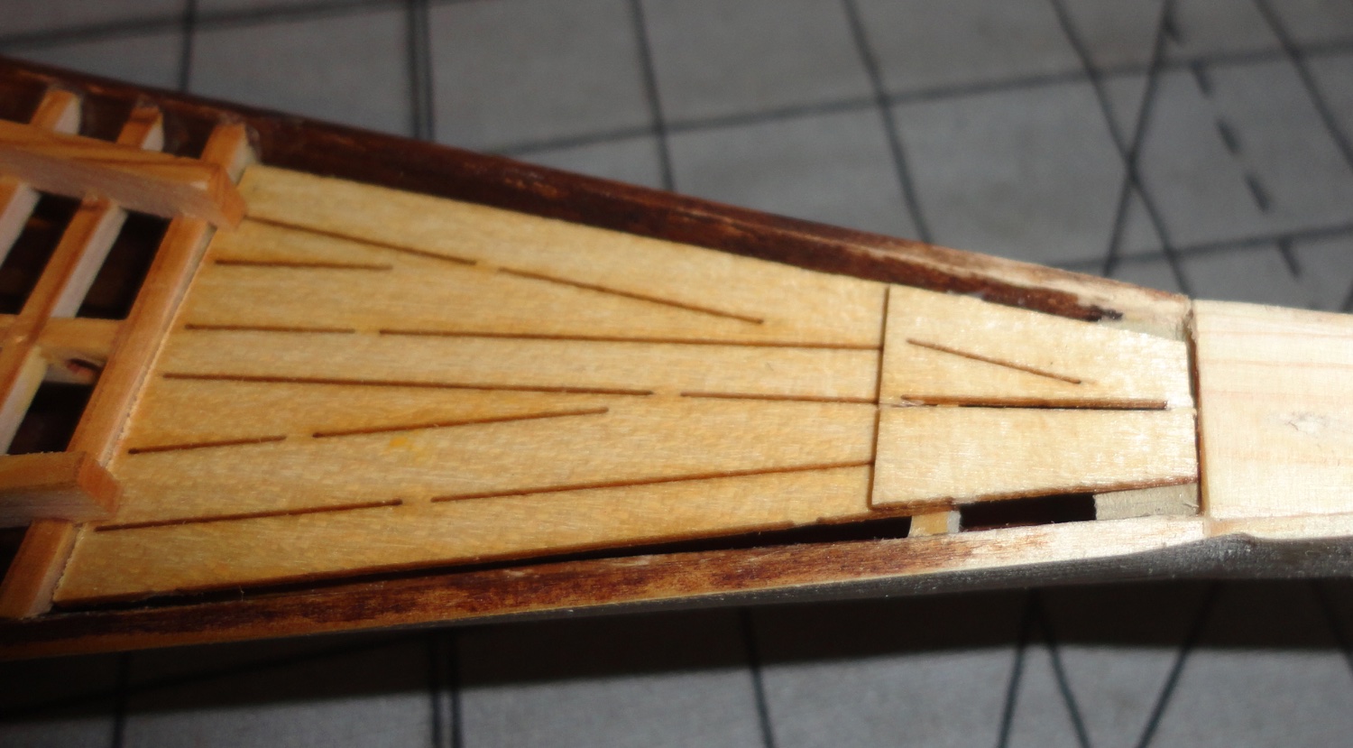
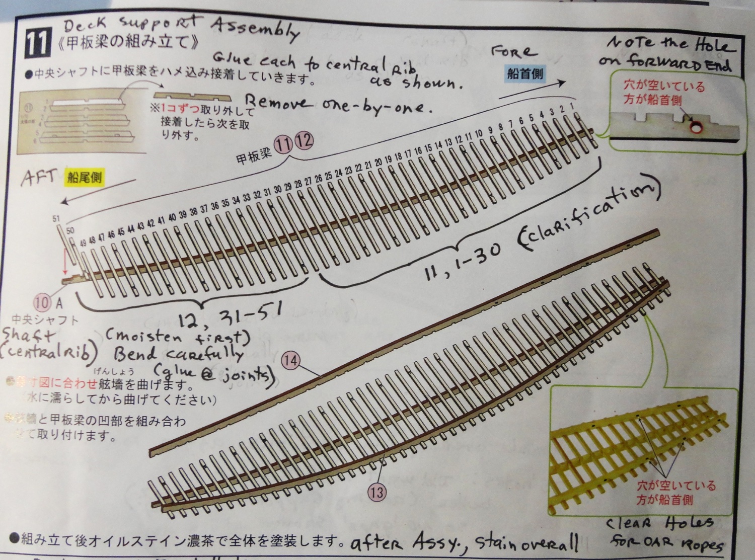
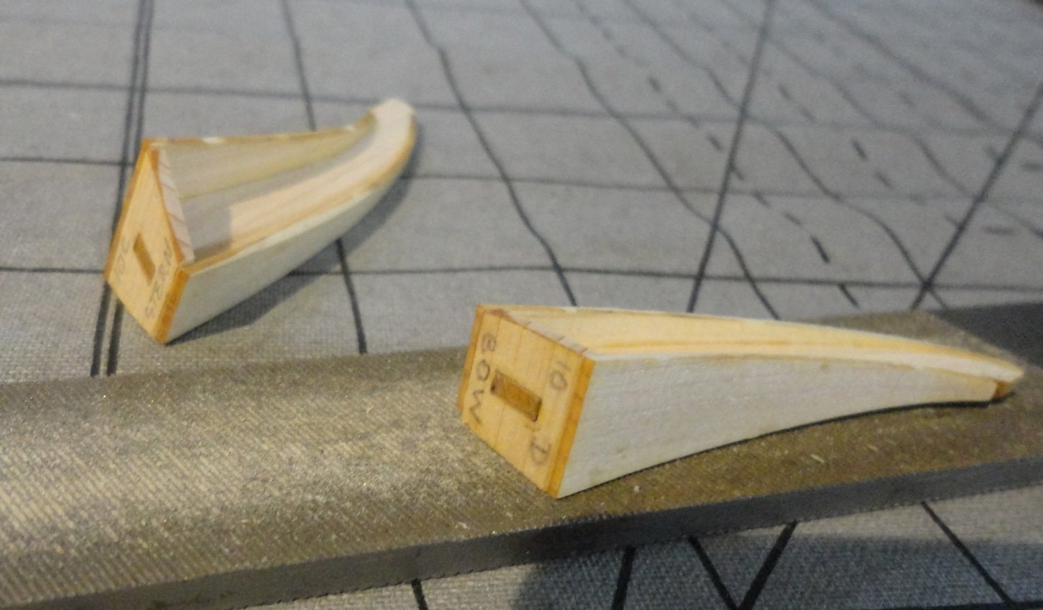
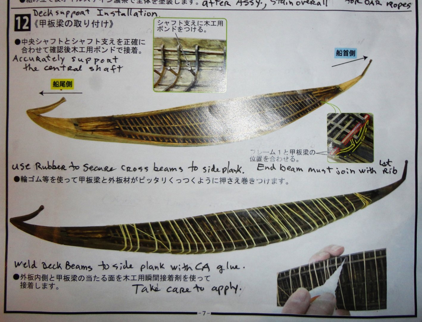
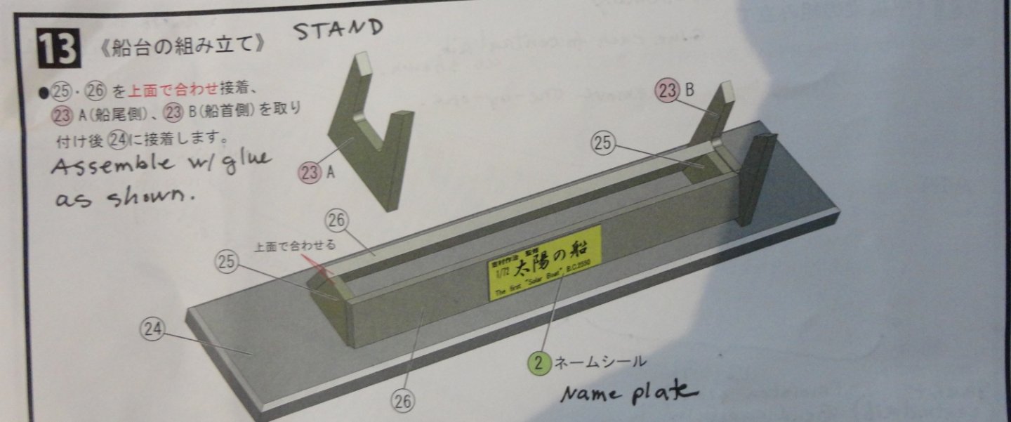
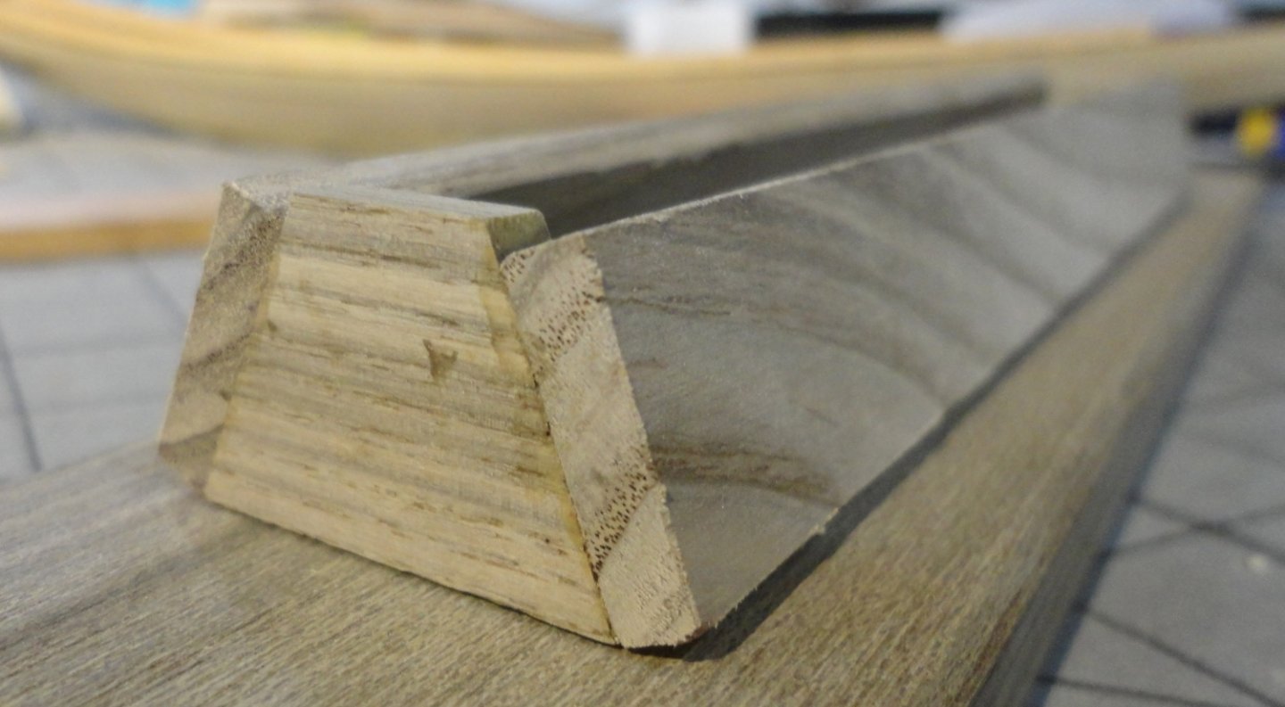
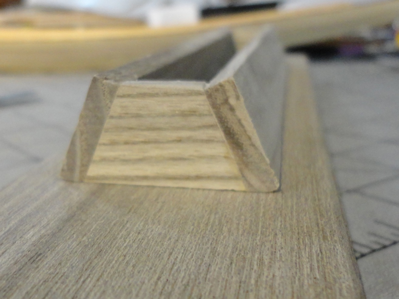
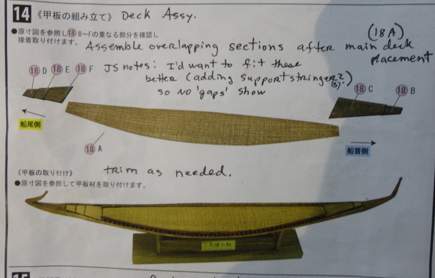
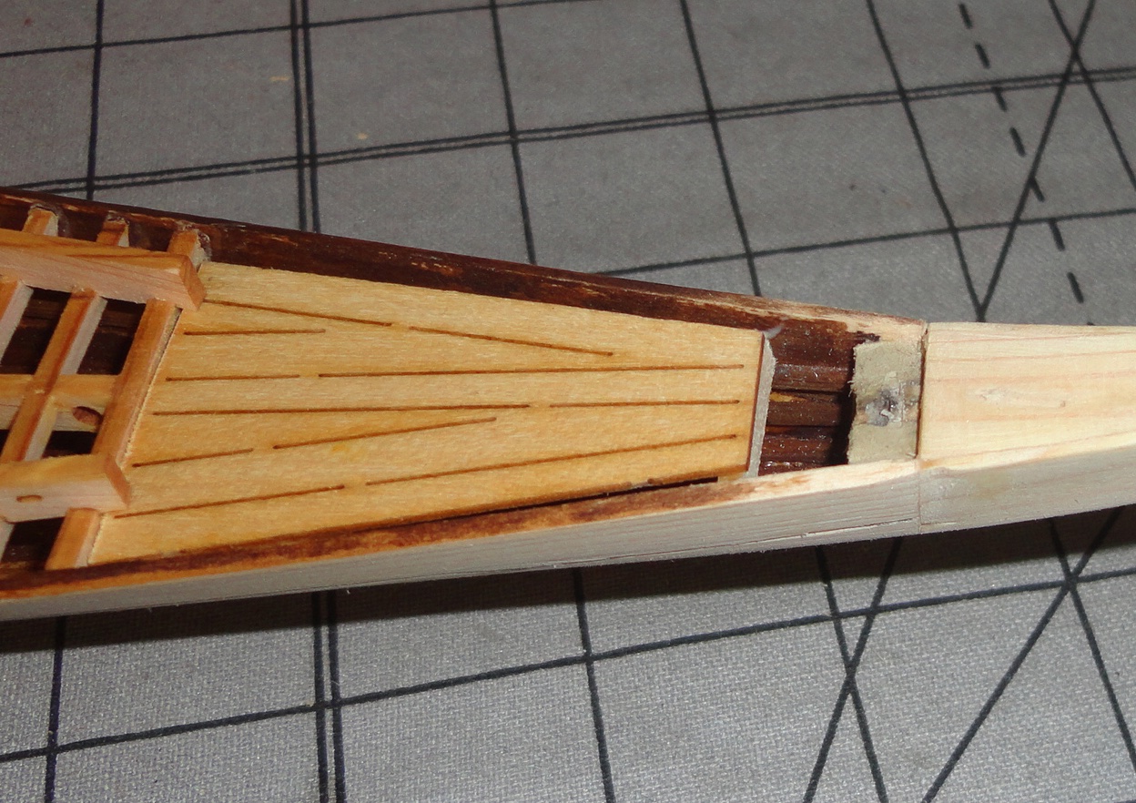
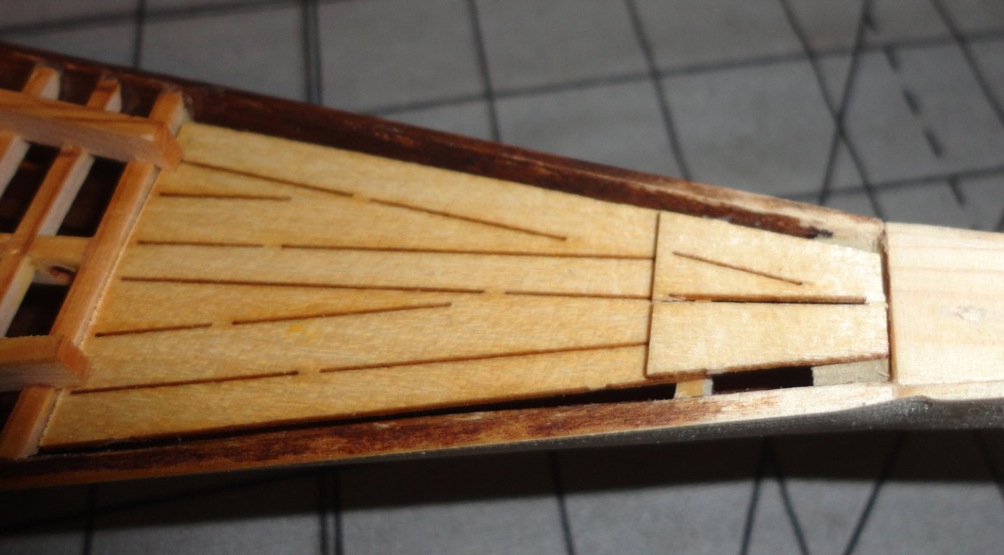
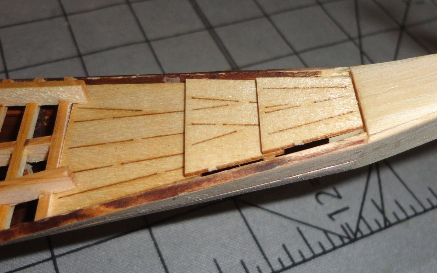
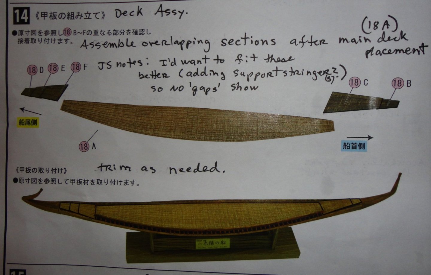
Ahoy! So there has been a little progress since the last post. First, are catch-up shots of the instructions. As mentioned before, wood glue was used only on a few places fore and aft, with CA applied to secure the ends of all the cross beams. I'm surprised how sturdy the assembly is (and also how light). The original was painstakingly roped (sewn) together, and the cumulative bonding force of all the ropes together made for a strong yet light craft. Put in the water, the seams would swell tight and leakage would be minimal. That reminds me of an oak water barrel I used to take on re-enactment weekends. Prior to the trip I'd run a slow hose into it from the side bung, and at first it leaked a lot. But after a couple hours the leakage slowed and eventually stopped entirely. I could rely on the barrel to hold water without leaking thereafter. Much later, when the barrel was emptied to dry - the wood shark back a bit and cracks opened up ... until the next time. Assembly of the stand is simple ... but a little sanding and a couple refinements are needed. Note the angle of the side pieces when placed on the platform. So it was rubbed on a piece of sandpaper to mostly flatten the bottom, and the end pieces were trimmed. The next instructional step refers to the decking. Heeding my own note, I put in a support for the first small deck piece near the bow. This supported the triangular deck piece at the desired angle. Then the smaller piece fit on top just as I wanted. These parts are delicate since besides being thin, they are almost completely layered into planks - and the smaller piece broke at the tiny connecting points during handling. The solution is to glue battens below (just as on the original ship) with trimmings of the stock used for the hull stringers. Then the connecting points can be scribed (as was done on the hull) to make the planking look continuous when viewed from above. SO dar, so good - so I repeated the fitting process at the stern. Now I've been thinking a lot about the side rail ropes that should be visible ... an optional step that would have been much easier to do before this point. That is, making the needed slots in the side rails while they are still flat, and installing ropes prior to gluing the deck into the hull. Why is it that I sometimes make things harder for myself? I could just go forward and forget about the side ropes ... but ... then I figured that with care, I could still make additional slots - then use a curved needle to get roping through the deck members. CA could secure some twisting of the rope that is adjusted to defend into the hull, that could then be tacked with CA. I did a trial on one of the existing slots and found that with care I could proceed. A post will me made after the process is complete, showing the steps involved. A minor 'bust', but one that will enhance the model.

- 63 replies
-
- 7
-
-
- Finished
- Khufus Solar Boat
- (and 1 more)
-
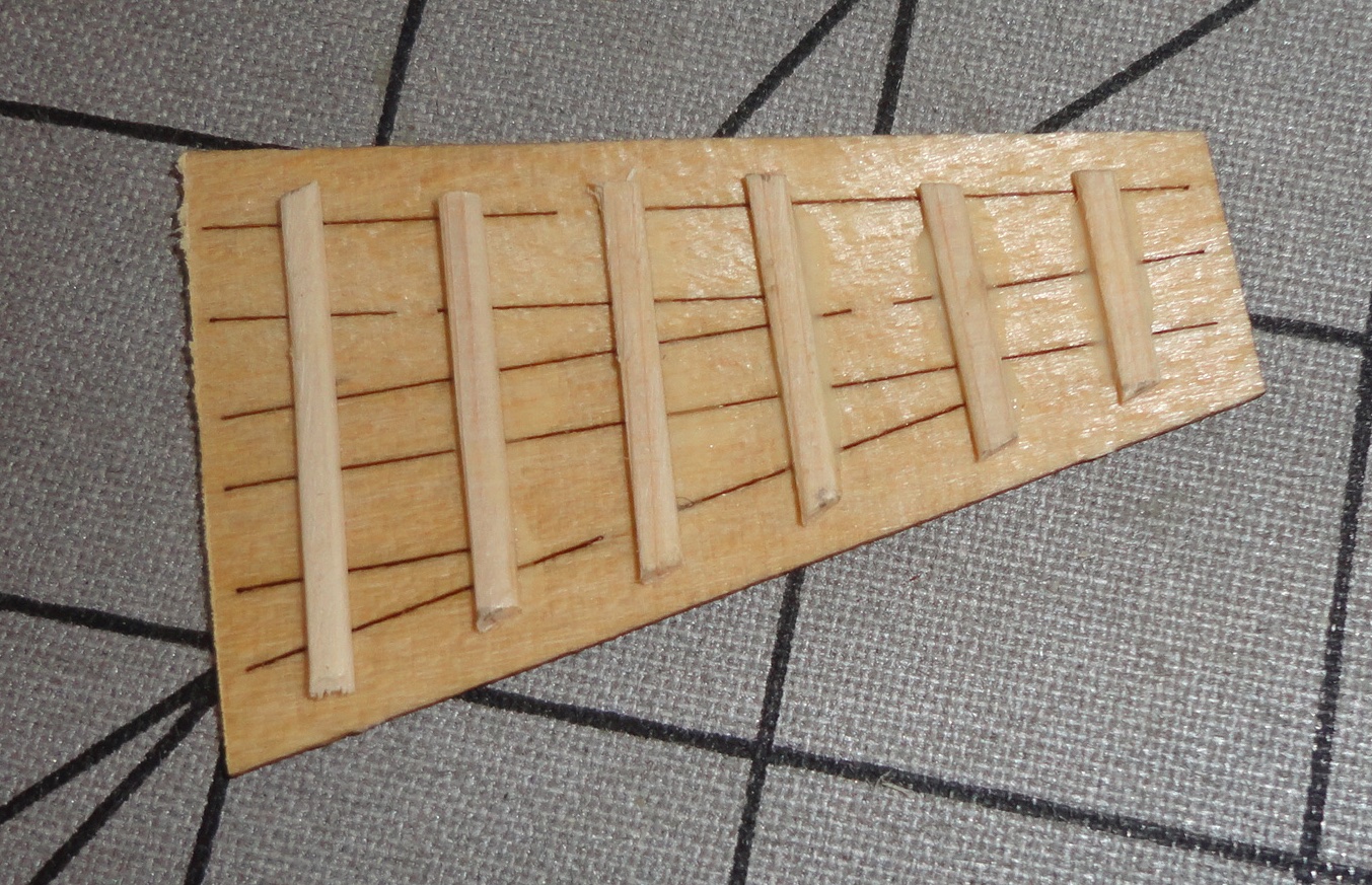
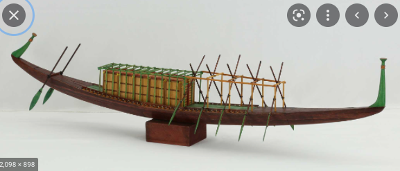
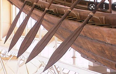
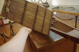
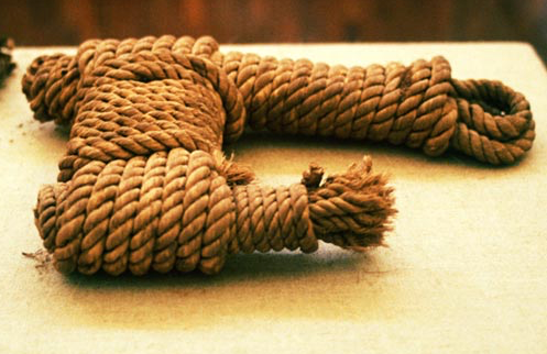
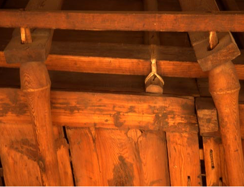
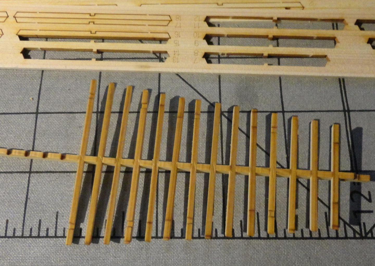
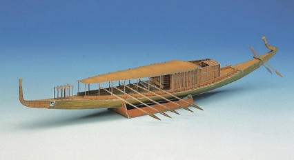
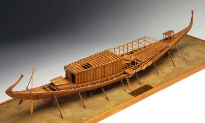
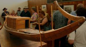
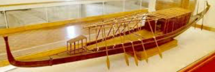
While thinking quite a bit about certain configurations, I did exterior sanding and 'connected' the un-lasered points among the planks (needed to keep multi plank pieces from falling apart before assembly) with fine X-Acto knife cutting. A mechanical pencil was used to darken those places, as elsewhere there is laser induced darkening on the edges. Next will come coloring, but not as dark as the interior. I looked for pictures of how other models were colored (some variation there according to taste), as well as shots of how the original was tied together for display. First, a sample model - using green in places and varying shades of brown, likely to make some of the structures more clear. The oars are in pairs - as they seem to be everywhere ... EXCEPT on the Woody Joe model, where they are alternating - as racing sculls have rowers offset from one another (reason being the narrowness of the scull). The oars on the original ship are displayed with them 'tied up' jutting right through the framework that likely supported shade cloth! Hmmmm, seems odd to my eye. Also, there is a lot of shallow water on the banks of the Nile, so when used the oars would be shipped out a bit - with enough of the oar shaft still inboard to counter-balance. THAT necessity would make for interference with the oarsmen IF the oars were in even pairs as shown above. Ah HA ... so 'offset' oars as designed into the Woody Joe model would allow for sufficient counter-balance without interfering with other rowers. Also, the oars are place more forward on the ship in the Woody Joe configuration NOT under any canopy (with its support structure that would only get in the way). I've looked at the museum reconstruction (which has an extended forward canopy structure), and the upper side pieces of the canopy top are lashed together to get the length shown ... with no canopy framework in back of the cabin. Woody Joe has some canopy frame forward - leaving enough room for uncovered oar positions, and the remainder of the canopy framework assembled behind the cabin. That makes sense from a standpoint of symmetry. Who would get to be under the canopy? ... Why obviously the Pharo, as well as his couriers/retainers, etc. NOT sweaty oarsmen. And why wouldn't there be a rear canopy for the notables? Woody Joe makes the rear canopy framework longer than needed, as the steersmen with their more vertical steering oars would be in the open. The kit incorporates 4 steering oars (possibly to make there kit unique, thus make outright piracy easier to spot), as two are seen everywhere else. I have to decide exactly how to proceed, so have busied myself with other things while mulling over the situation. Note also that there is a series of ropes going all the way down the side deck rails on the original - in order to secure to battens below deck on the hull. The removable hatches fore and aft allowed access so everything could be tied-off under the deck by a worker. I though a long time if I should try to make a series of slots going down the side rails for those ropes, but was stumped on how they could be tied on a small model. Note how the oars are secured using the same slots as the deck ropes ... so there is no indication exactly WHERE the oars positions were on the original. Hence my thoughts that the practicality of staggered oar positions is just as plausible (if not more so for ergonomic reasons) than any other. The jumble of parts found at the base of the Great Pyramid happened to be a 'full-size kit' ... with NO instructions. Obviously many things have to go together as mating parts, but other aspects of configuration (e.g. oar positions and canopy frame assembly) are open to interpretation. Above shows how the decking was tied underneath with battens as shown on this hatch from a large-scale model. A lot of the construction rope isn't visible from the outside, although some of the rope and attachments are seen. For reasons of sanity (and considering to keep this model kit in the beginner class) I've decided not to try and incorporate ropes other than to secure the oars. A sample of original rope made from some kind of twisted reed material. I want to re-visit a PBS NOVA show (first aired some years ago) called 'Building Pharos Boat'. It doesn't seem to be available for free streaming now, but those with a PBS subscription can access just about everything in the PBS library. One series never shown since the 70s (and I haven't seen anywhere) is 'The Fortunes of Nigel' - about intrigue in the English Court of James the First. I found a detail of part of the cabin, and it shows that the tops of the canopy supports have a flared head with tapered ends that peg the canopy cross members and side rails. 'Seems that everything else was tied together. I suppose they could have turned the round verticals on a foot treadle lathe, often referred to as a spring-pole lathe. The kit kit instructs to 'round' pieces of square stock for these, but that seems a bit laborious. I may end up turning them on a miniature lathe (Unimat). I've found my Dad's old Unimat that he gave me quite some time ago very useful on occasion as it has a 4-jaw independent chuck, a 3 jaw 'universal' chuck and a cross table. It lacks a live center, but I've improvised as needed. It doesn't have the power to take anything but light cuts on aluminum and brass - or a VERY light cut on mild steel.
- 63 replies
-
- 5
-
-
- Finished
- Khufus Solar Boat
- (and 1 more)
-
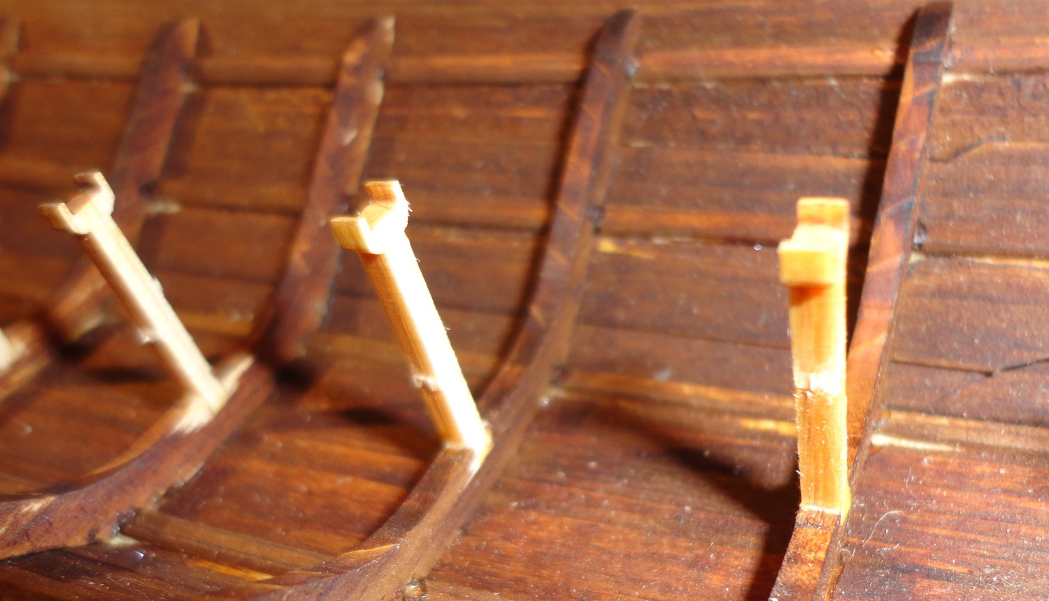
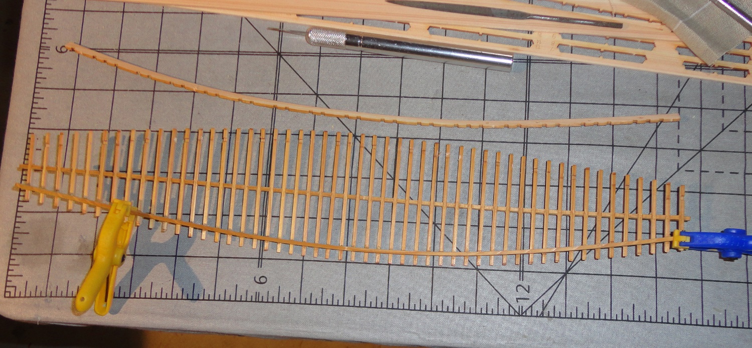
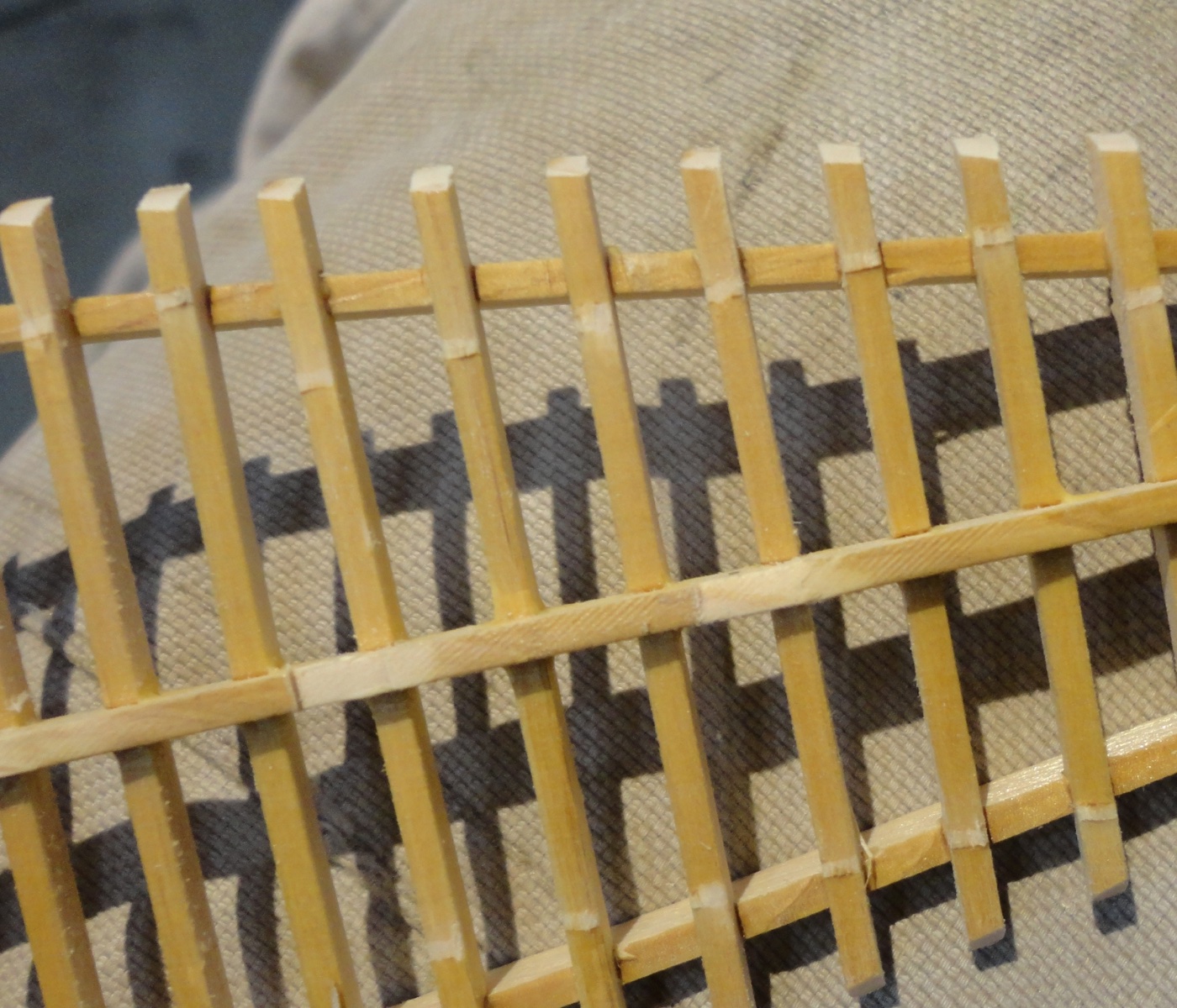
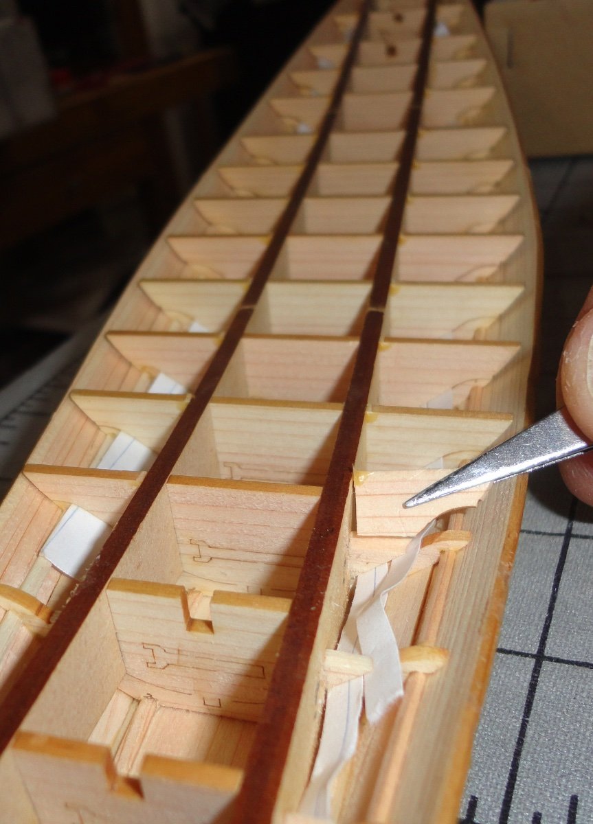
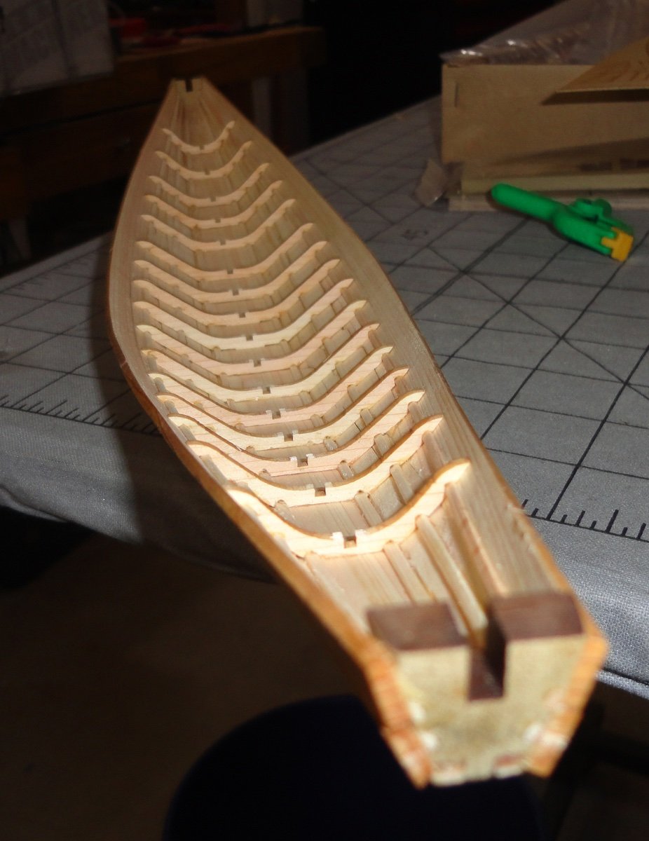
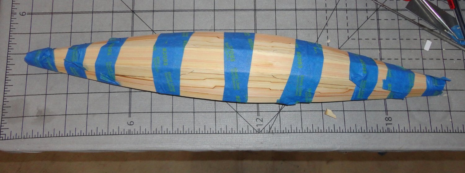
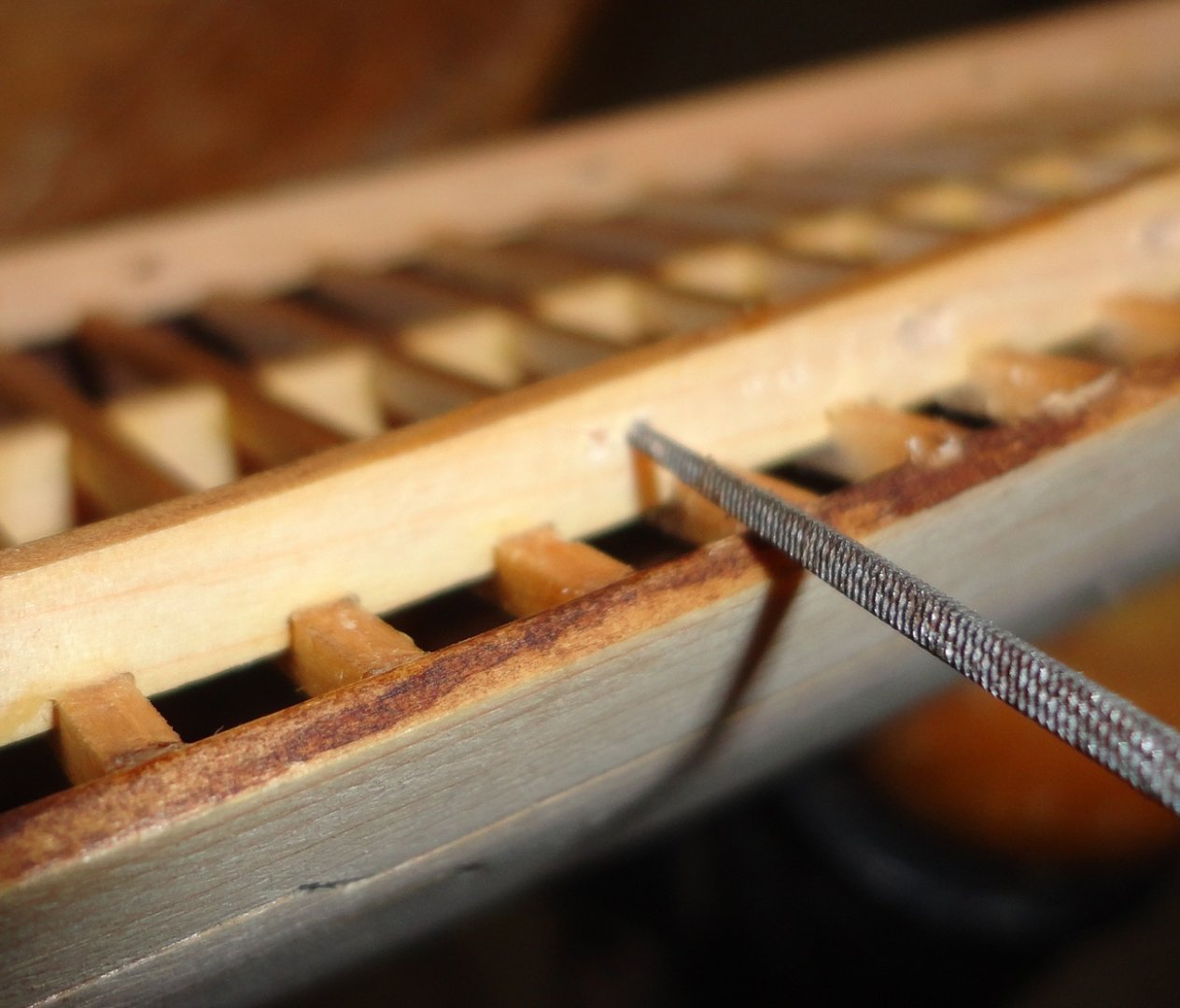
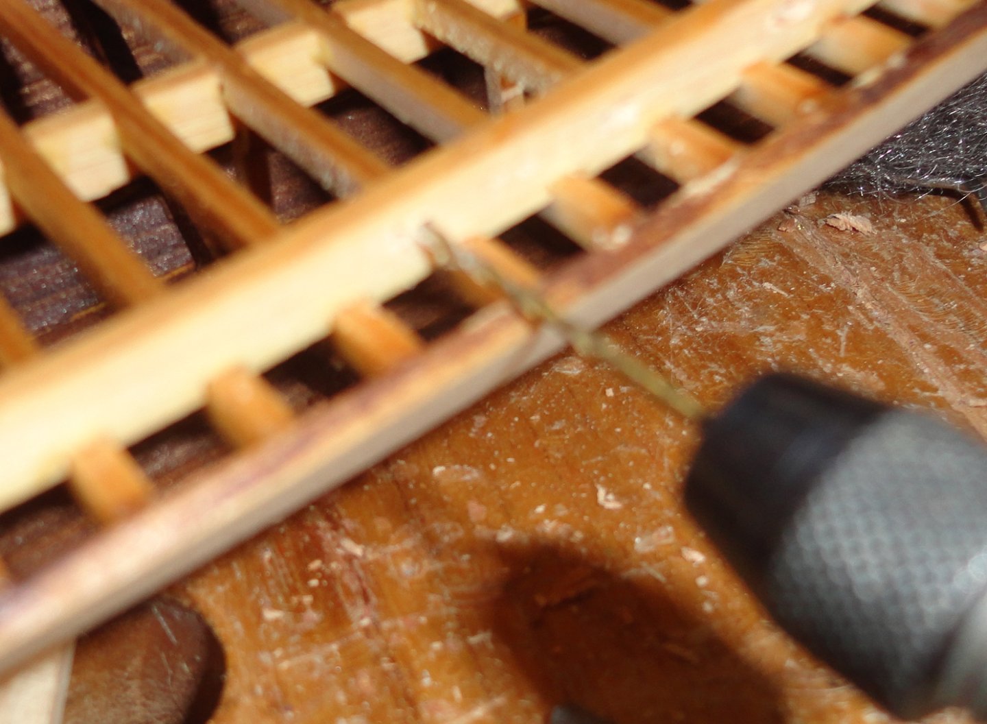
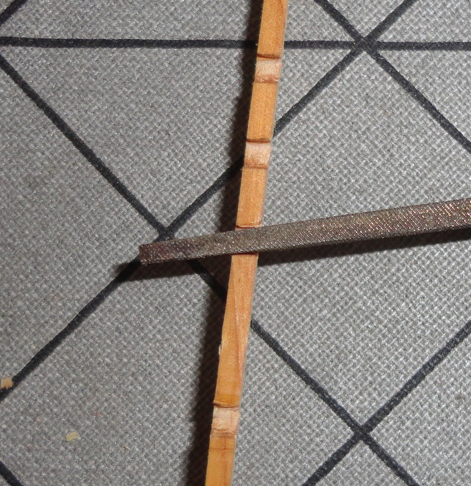
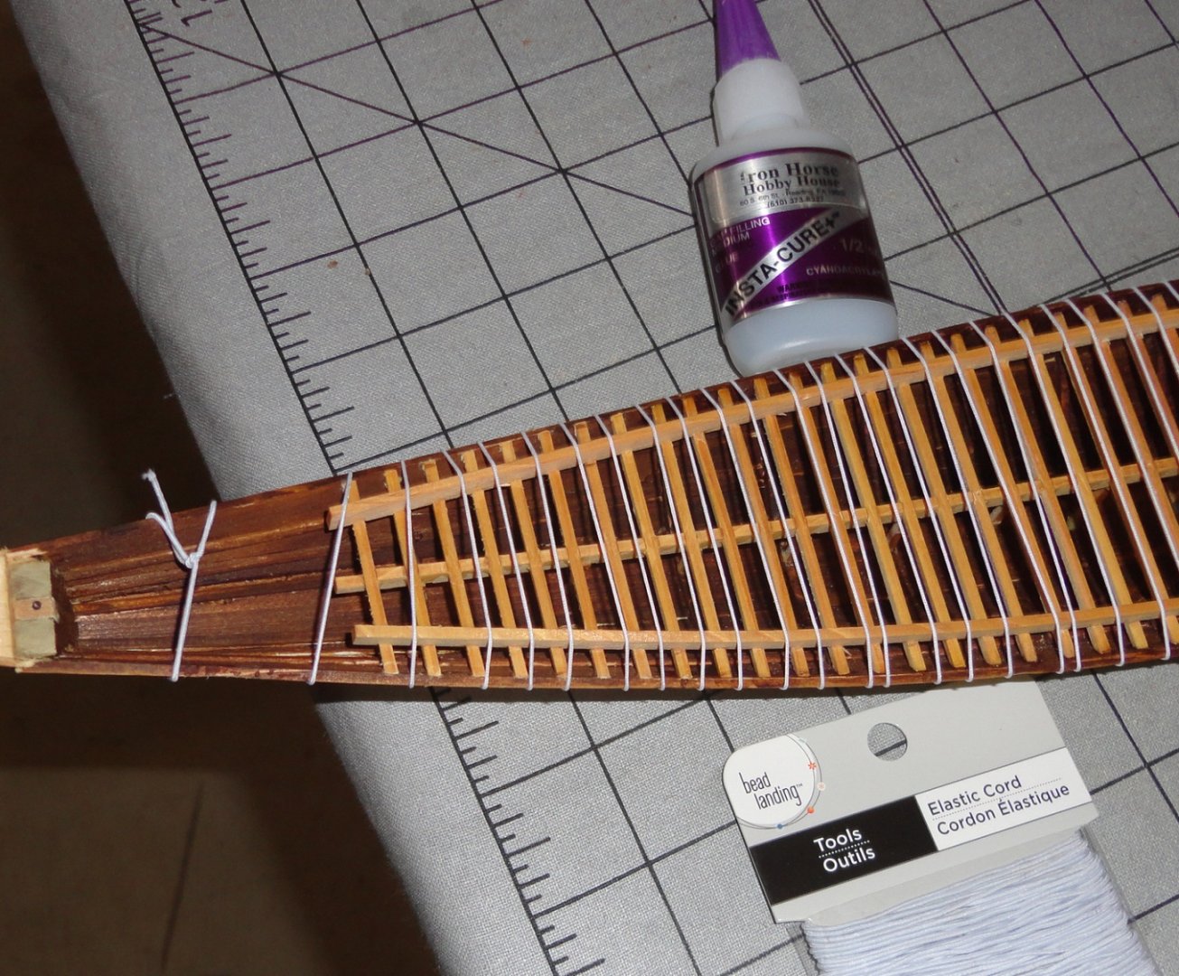
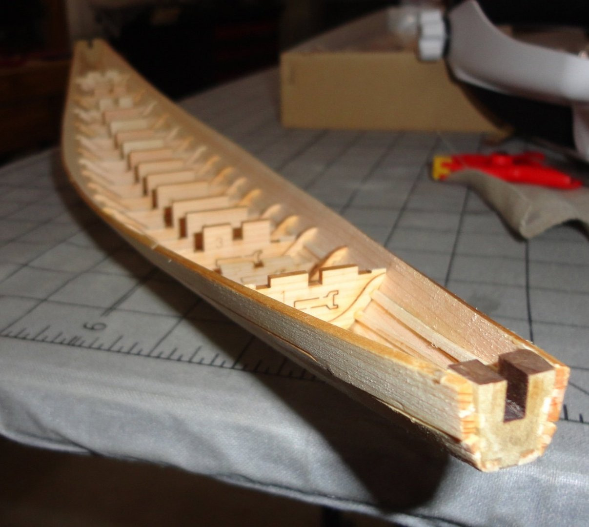
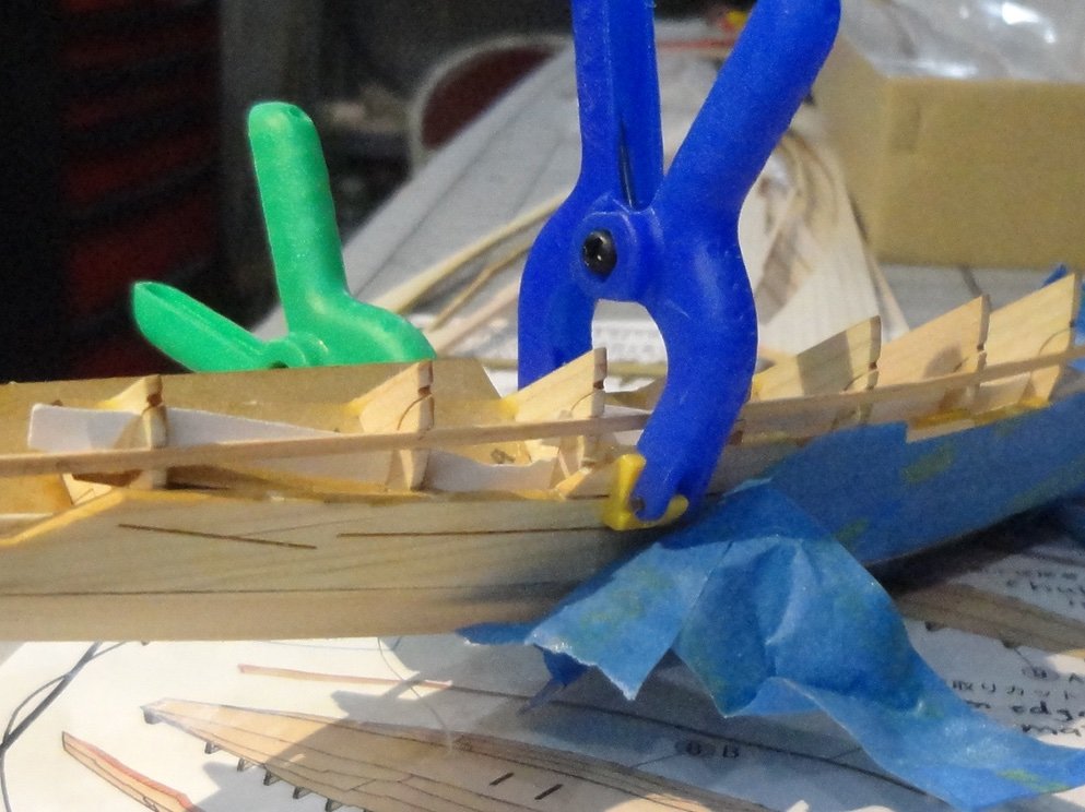
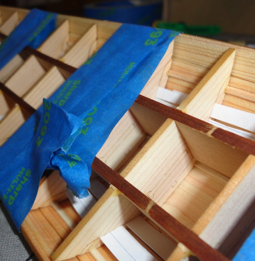
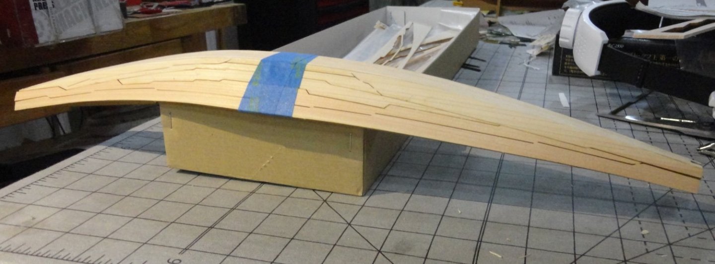
Its back and forth between sundries at this time of year, but I try to do at least something on the Khufu boat at least every other day. A few things concerning this Woody Joe kit: The Japanese cedar wood is pretty pliable once moistened - and that does not mean soaked, although the thicker planks were wet a fair amount and held over steam or a gas flame to be pliable enough to bend 'width-wise' (versus the 'easy' way). The wood is very light and can be 'dented' (especially when wet) and is easy to carve (so a little care is needed not to over-carve ... easy to take off - hard to put back). I do like working with it (easier than some hardwoods) and the original was made of wood in the same family (Lebanese cedar). In my kit review I noted that ideally the stock would have been all heartwood ... but what was supplied is acceptable. Those following this log can see that the translated instructions (while helpful enough) are a little light in some respects. My additions should fill-in a lot of the gaps. However, the sequence of assembly in the instructions turned out to be the one I followed. I am truly impressed by the quality of the laser cutting. The discoloration where cut is kept mostly to a minimum, and there are no 'flare burns' on the reverse side as seen in some kits - and certainly no charring. I'm amazed how fine the cutting line is on many parts - most notably on the deck cross supports that are to be assembled next. The attachment points (not laser cut) on them are only on the underside (not visible on the model) so I didn't bother to trim those points, while on other parts just a slight trim with an X-Acto is all thats needed. The design is very precise and, aside from the trial fitting and adjustments needed for any wooden model, things go together pretty well. I revisited a few photos of the original, then refined the lotus ends of the bow and stern to be a little more lotus-like ... small but significant details, so I might as well do what I can along the way. The supports were popped out of the numbered bulkheads (previously removed) and glued in the notches of the corresponding ribs with wood glue. The fit wasn't tight, and I had to fiddle a bit as there glue set up so that they would stand straight ... in hindsight small pieces of stock could have been glued to the front and back of the rib to make a 'socket' for the verticals to fit into. That would limit play fore-and-aft while the glue dried ... but as I would discover later, having some play when assembling the deck support assembly would come in handy - as it was tricky to fit everything in during the trial fit/adjustment process. Sparing use of regular Titebond did permit forward and lateral adjustment - perhaps PVA might have been appropriate in this application. Very little of the interior will be visible on the completed model, so there was no need to round the top surface of the ribs (or the verticals). The joinery on the original involved lots of reed ropes through adjoining planks, ribs and stringers ... also not visible from the outside - ergo no need to try and simulate that. I did want the interior to be a medium brown, so that was done earlier. The coloration on deck (and the hull exterior) will be lighter. As you will later see, the edges of the deck cross beams were tanned a little where they were laser cut (the edge that shows) - so I'll not add color to them and they will stand out from the darker interior. Below is the next step provided. NOTE: I first trial-fit the central beam to all the vertical supports, and found that I had to moisten the beam and alter the upward curve (fore-and-aft) ,or 'loft', a bit to get the best fit. The fit of the cross beams into the center beam was snug - 'almost considered not using glue, but then an attempt to fit the first curved side beam convinced me that gluing would be a good idea. Woody Joe offers models of traditional Japanese buildings (temples, etc.) and they likely have engineered them to fit exactly - as the cross beams fit in this instance. The side beams were laser cut with the needed loft fore-and-aft, but had to be moistened and bent sideways (not hard to do) to conform with those cross beams having notches. Getting the first one to fit required a few adjustments ... because I didn't appreciate the right-angle nature of the notch (the piece was laser cut flat), bending the rail did not alter the angle nature of the notching. After bending, they would have to be like a parallelogram. OK, so to get the right fit, the notches had to be angled slightly with a small square file as shown below. There had too be a little relief filed in the notches of those cross-beams that were notched ... harder to do once glued to the central beam. Pre filing those cross beams is another tip I learned in hindsight. Also, the amount of filing is slight the closer one is to amidships - with a little more filing as one goes fore or aft. Once the side rails were glued and cured, the strength of the deck assembly was apparent. Fitting it into the hull would also require some 'fairing' of the cross beams, as the hull form is dynamic. The photo below shows a small flat file used to fair the ends of the cross beams into a smooth curve, and there also had to be a curve filed from top to bottom of the beam ends - as the hull curves inward. 'Sounds hard, but it was done with the same file without much trouble, and you can see also a few places on the center beam where a little was filed away where some of the hull vertical supports towards bow and stern tended to elevate the center beam too much. (Yeah, they could have been pre-faired before gluing - but their delicate nature prevented further adjustment, so a little material was filed from the center beam to compensate.) The photo below shows the cross beams being faired. After enough trial fittings, there was gapping between the cross beams and the hull amidships ... as indicated in the instructions, this gap would be closed by pressure from banding before using CA sparingly at the joins along the hull. The next step showed rubber bands being used to bring in the sides of the hull a little, but I had the idea of using thread covered elastic banding (from the craft store) to just wrap around and around. Each loop maybe had an ounce or so of pressure, so 50 loops provided an aggregate of some 4 pounds of clamping force. This made everything fit together nicely. BEFORE the elastic was wrapped, wood glue was put on top of the hull verticals, the tops of the first and last rib, and on the ends of only the first 8 cross beams at either end. AFTER wrapping, all the other points of attachment were given a little 'thin' CA (note: it is easy to apply too much, the smallest amount 'wicks' into the joint - and the wood). Then, because I could see some slight gapping of the beam ends against the hull here and there, I went over the beam ends with a little medium 'gap filing' CA. Cotton swabs removed any excess. After setting, any sheen from the CA was dulled by rubbing a dental tool over the affected area. Dental tools are also useful in removing any excess Titebond. The hull was left along for a few hours as I busied myself around the house and helped the Admiral clean parrot cages. When I removed the elastic, I was surprised to see how strong the hull was when I attempted to spindle it. 'Don't know how much force any single beam end glued or CA'd to a hull plank would take before parting, but there are 51 cross beams - and with 2 ends apiece, that would be 102 times the force any single joint would take.


- 63 replies
-
- 5
-
-
- Finished
- Khufus Solar Boat
- (and 1 more)
-
Saw miter gauge slots
Snug Harbor Johnny replied to kurtvd19's topic in Modeling tools and Workshop Equipment
The 'Chicago Tool' saw sold by Harbor Freight has a slot .410 wide x .100 deep to accommodate a slide .400 wide x .080 deep. No fence, though. -
Epoxy glue
Snug Harbor Johnny replied to mtaylor's topic in Painting, finishing and weathering products and techniques
When using 5-minute epoxy (JB Weld has worked well for me) in small quantity, I'll 'finger-mix' it on the end of a door shim to incorporate it well ... actually 'whipping' it a bit. Soon I sense the temperature of the mix start to rise and the viscosity begin to thicken as it 'kicks'. I might use the index finger as an applicator in some cases, or wipe everything off and use a dental tool if convenient to the application. There will be just enough time to position whatever is being glued, and I'll leave it alone and do something else for a while. -
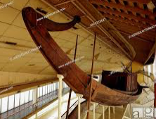
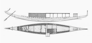
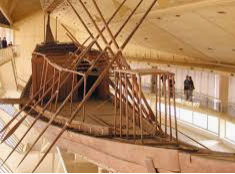
'Looked for images of the museum ship and replicas to get some ideas on how to represent the model ... not really 'busts', but perhaps preferable v/s how the ship is shown in the kit materials. One version with the rowing positions shaded. Note above & below that there is one pair of steering oars. The real deal below. A large scale model at the museum. BTW cross beams did support the removable hatches. Oarsmen may have stood and rowed by pushing out and back (varying the blade angle each time), similar to a Far Eastern method of rowing. Another view of the restored ship on exhibit Just more 'food for thought' ... why rush?
- 63 replies
-
- 4
-
-
- Finished
- Khufus Solar Boat
- (and 1 more)
-
You might try making a form with a mild bend (placing a pencil beneath a phone book?), placing the warped piece on top aligned with the curve (but opposing), then letting a ream of paper (or another phone book) lay on top to 'force' the deck into curving the other way. Left overnight, it may 'spring back' to approximately flat ... possibly a trial-and-error process by adjusting the re-bend as needed.
-
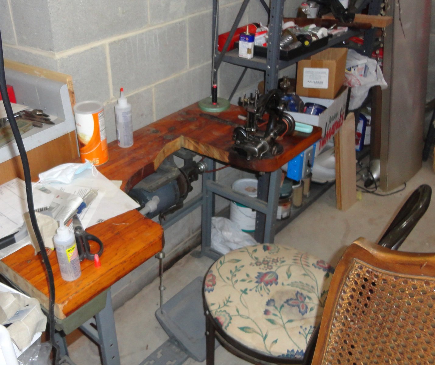
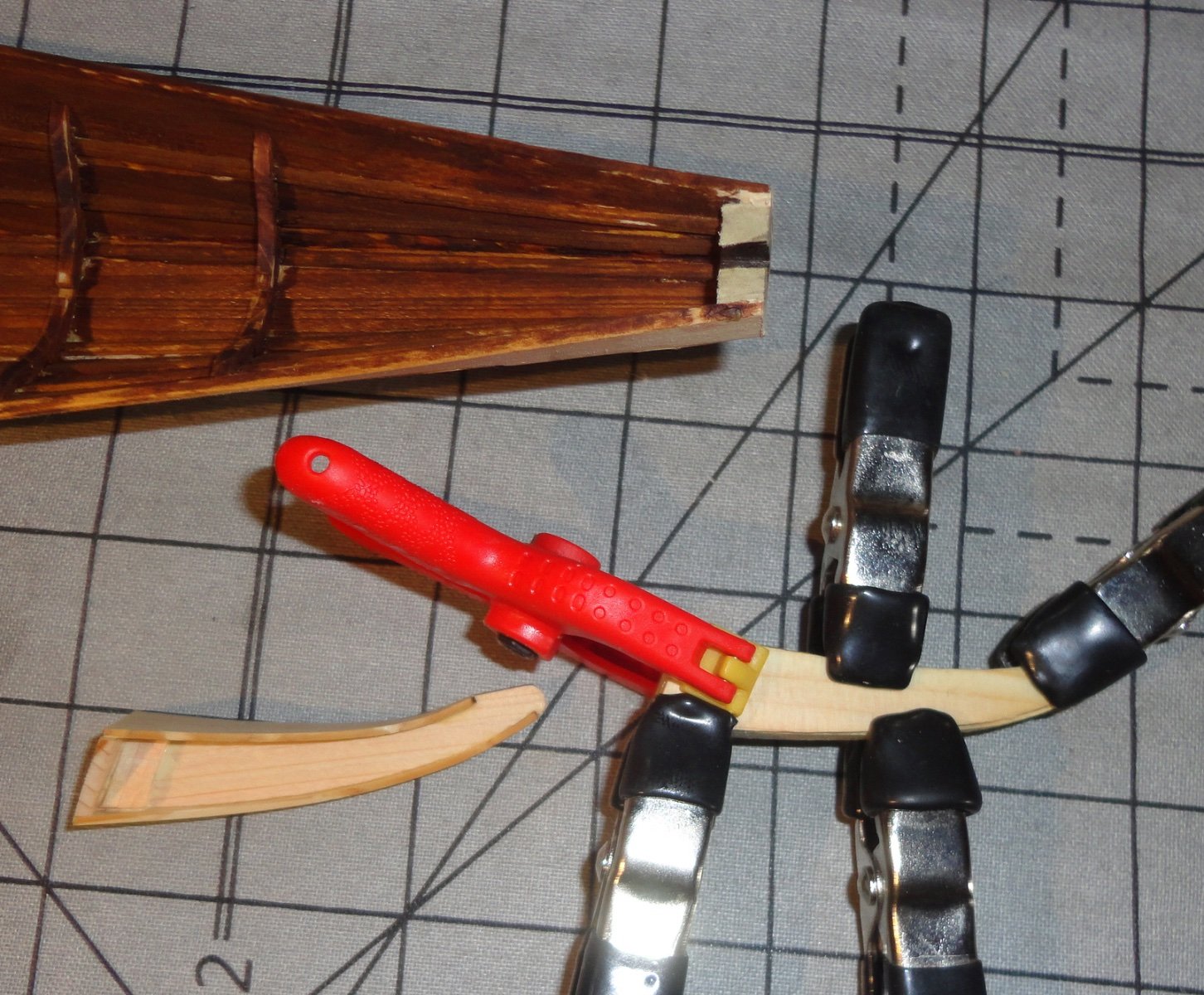
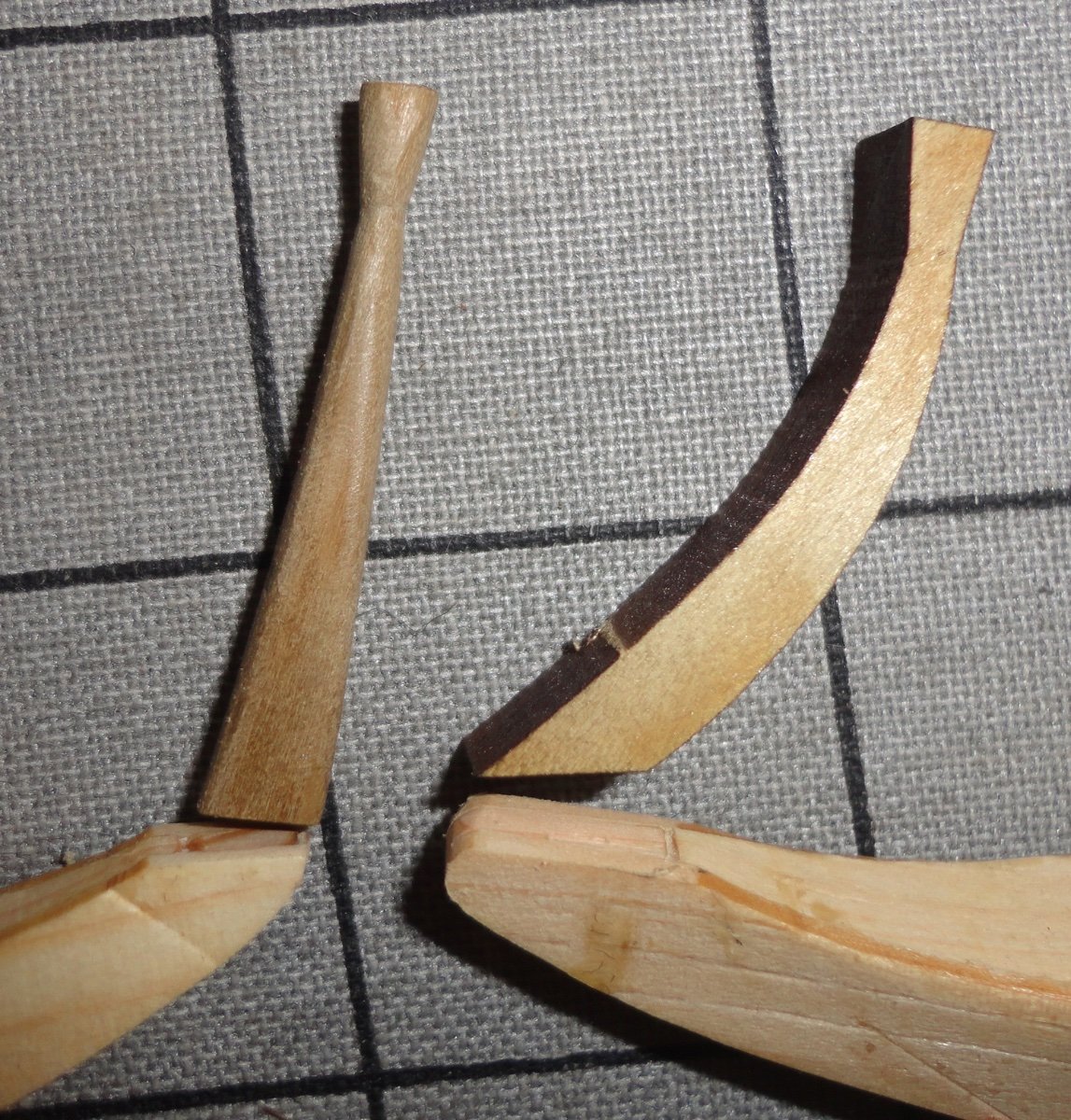
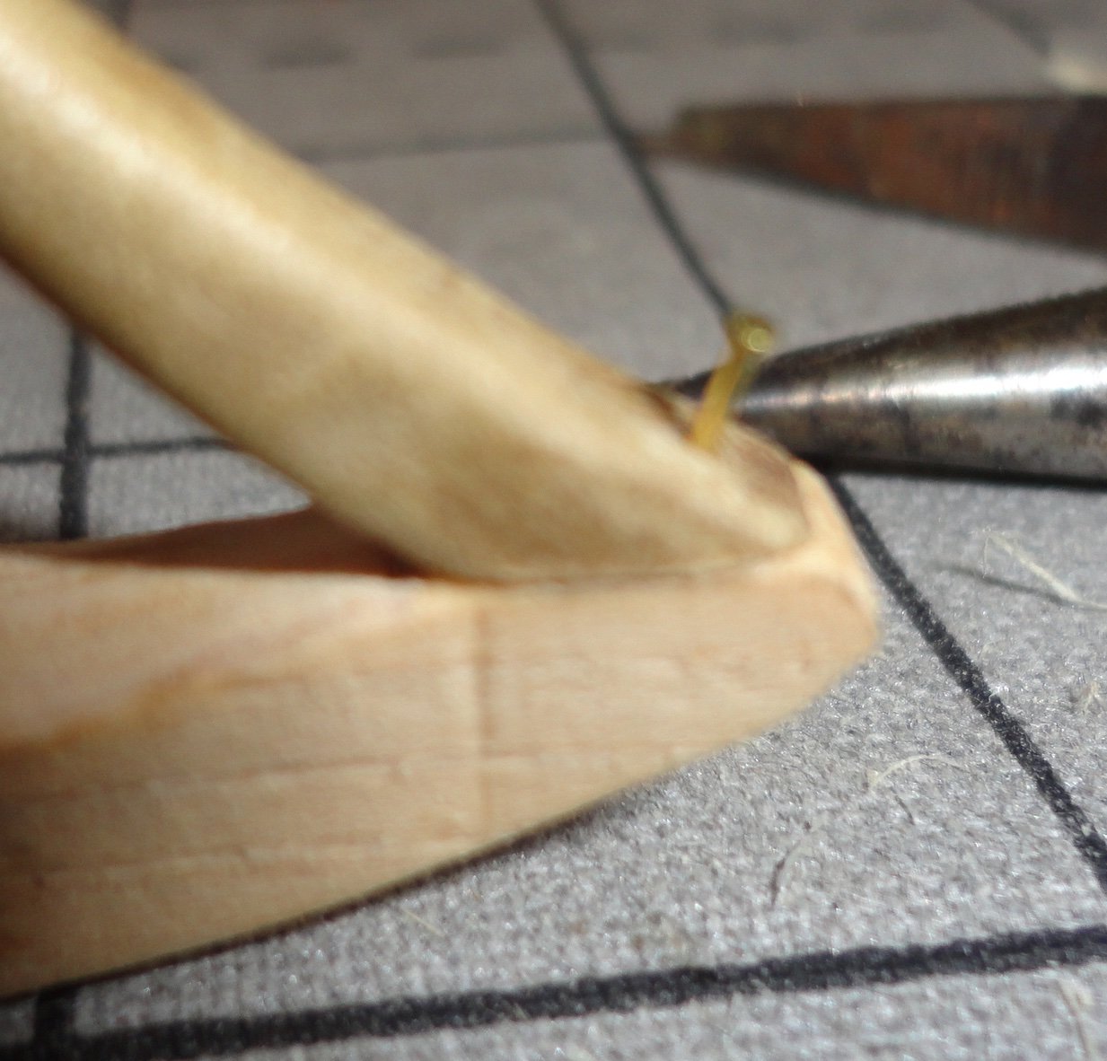
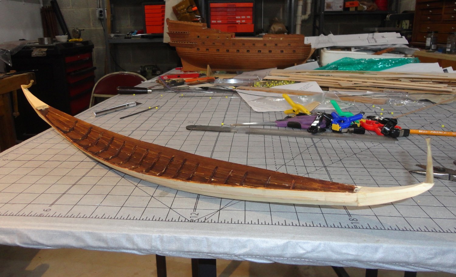
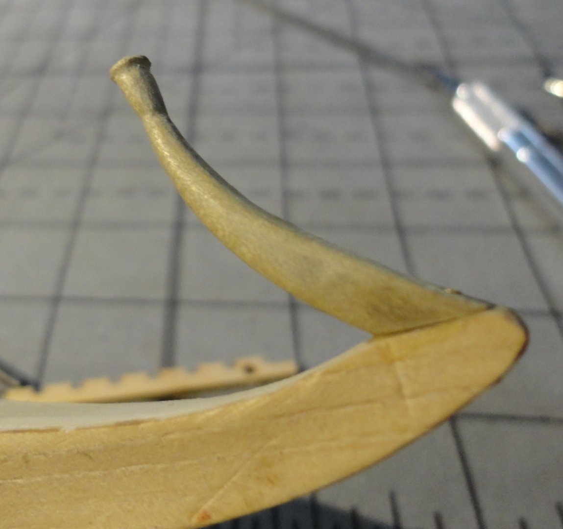
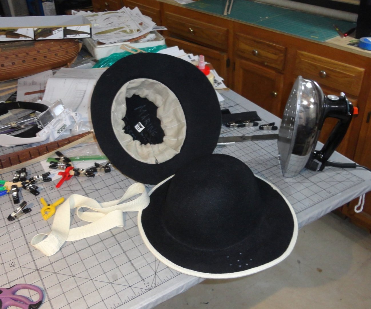
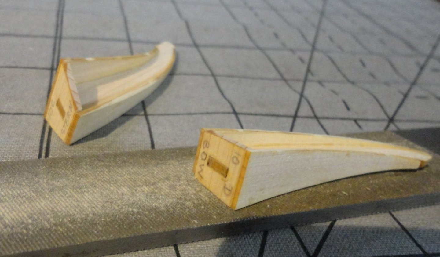
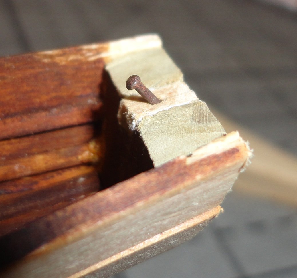
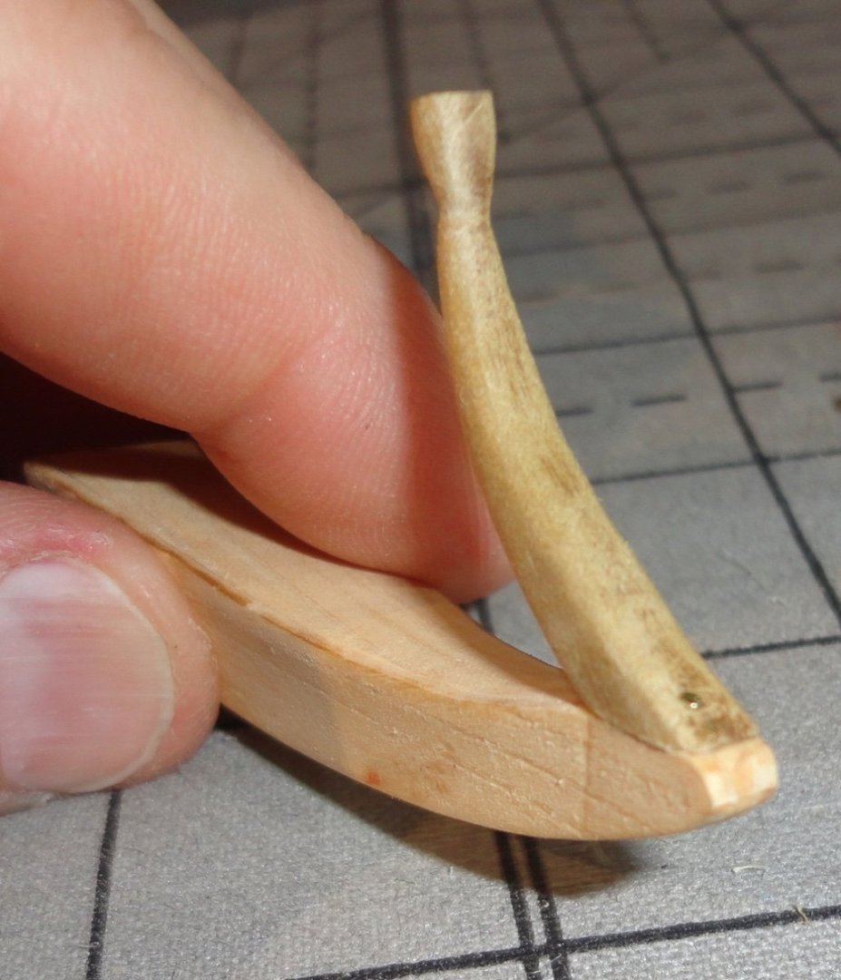
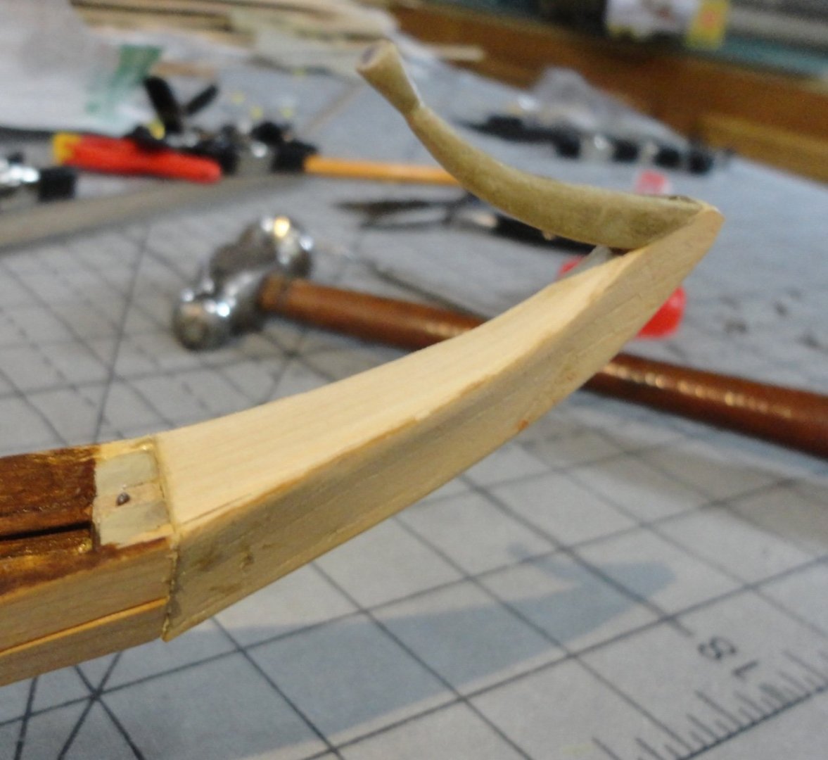
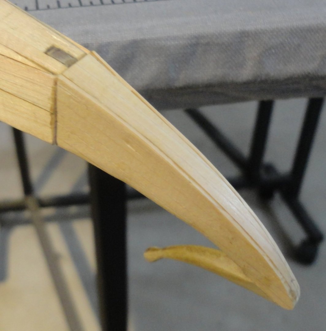
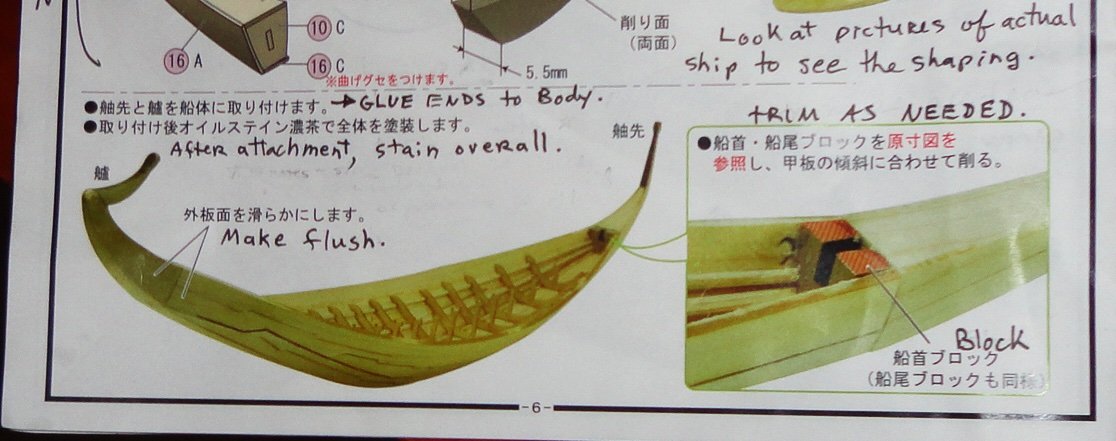
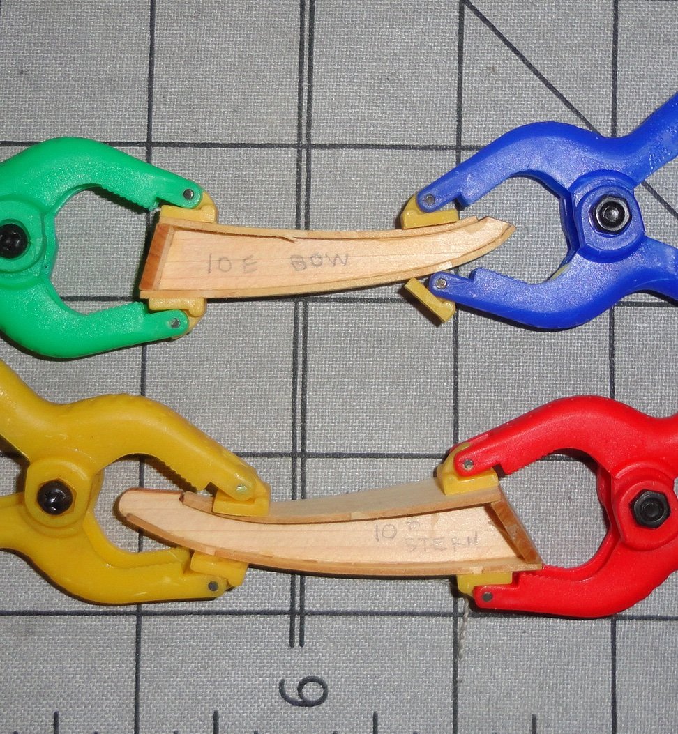
'Been put to work on an Admiralty project for a few days ... also had to finish a hat order - the last two done this morning (cut down Colonial Marine hats). Sometimes the Admiral thinks I'm a 'mad hatter' of sorts. Well, this sideline is part of her cottage industry and I'm 'in for the duration'. The adjustable liners are sewn on a 100+ year old Wilcox and Gibbs hat machine - reconditioned and maintained by yours truly. Back 'on topic' ... Another reason for the break is that I was re-thinking the 'plan' mentioned in my last post. Ah, 'The best laid plans of mice and men oft gang aglee.' By that I mean that I thought of four other approaches to what still seemed to me a 'sticking point' - the attachment of the delecate ends to the fore and aft end pieces, then the attachment of those assemblies to the bow and stern blocks with something more substantial than just butt joints. 'Didn't know how to clamp (having discarded the 'use a screw' idea) and I didn't want to use 'finger clamps' for an hour. So I settled on the idea of pinning and decided to just forge ahead ... "Screw your courage to the sticking place." First I had to fair the sides of the end pieces - done with a file. Then the ends of those pieces AND the faces of the bow and stern blocks had to be flattened to meet flush - also done with a file. As for the angle to trim the end block to ... I decided to look at the full size plan in the kit - what a concept! (Duh.) 'Still don't like their 'stacking' of the auxiliary deck pieces, but I can do it slightly different. An X-acto was used to trim (carefully) the unwanted material to get an approximation of the defending angle needed - it will be covered-up anyway. Below is a trimmed block and putting the side pieces on one of the end extensions. The uncovered piece on the left has had extra wood glued to where it will join the hull. Then the thin end projections had to be carved - so I whittled the first one (bow) to rough-form, and finished with small files. The stern end on the right (below) has yet to be shaped (for comparison). There is some real modeling involved to it. OK, now to 'brass tacks' (actually one still and one brass for each end). I plugged the notch in the stern end with part of the 'central keel' used earlier in construction (now removed) because that piece had already been shimmed to fit closely. I used a #60 drill to hand-turn a pin chuck to get a pilot hole for the steel mini-brad (found in old Billings or Steingraeber kits). The plug was glued-in and the brad pre-placed to push into the end piece to be added. The next picture is out of focus, but I glued the stents projection (now carved and smoothed) with a tiny brass pin included in the Khufu kit. Hmmm, my opinion of them has gone up. The obsolete (Admiralty cast0off) camera I'm trying to use keeps shifting itself from ordinary pictures, to video filming, to 'close up' mode ... at random. But below is a relatively focused shot of the pin now pushed in . I intend to get a pin (brad) 'pusher' that will work better than the plier ends or a file end. With the pin in place, the end projection (lotus) is reinforced and feels relatively firm. Once the glue cures, it will be strong enough. Hey, you know how delicate bowsprits can be ... especially the ones on plastic models - and even more delicate are the cathead whiskers or martingale on the Revell Cutty Sark kit. So why should I worry about glued wood that is thicker? Ahhh, the light at the end of THIS tunnel (doubtless there will be more later). The stern end is glued and pinned and after curing can be further faired. A view of the underside. Now both ends are inlace and I can relax a little. BTW, the Khufu model is about the size of the Wasa project (1:100 first Billings version) ... just under 23". That is not too big and not too small. Getting this far with the Khufu kit has involved enough modeling skills that it is no 'pushover' for a 'beginner' - yet affords real opportunity to gain experience (as long as one has a little patience) and is wiling to repair the occasional mis-step ... something we all have to do.


- 63 replies
-
- 6
-
-
- Finished
- Khufus Solar Boat
- (and 1 more)
-
Very interesting photo ... likely among the changes made in South America before departure for Antartica. It shows that the original installed side railings of the central cabin were removed ... and that cabin was enlarged by decking out to the gunwales AND rearward to the stern cabin to make one giant living space for the long Winter(s) ahead. Check out the ingenious build log of the Endurance (ex Polaris) in a lightbulb done not long ago, where the builder's intent was to show this "final" (so they thought) configuration of the ship deep into Polar ice. I had not realized just how extensively re-modeled the ship was, but a careful examination of the many photographs extant (and one has to 'dig' a little to see some of them, as many institutions/individuals have got into the habit of 'copyrighting' any old photo in their possession - even though the material was already in the public domain from the passage of time alone, plus prior publication) reveals that a major re-decking (via extension) was done. So there are many 'configurations' to choose from when deciding what point in time/circumstances to represent in a model. Aside from the original Polaris (enough photos exist), there is the 'mod 1' version of Endurance as it set sail from England ('T' shaped walkways w/railing and 2 side gangways to make a dog run with railings, kennels present but no enclosure over the steering tackle), a 'mod 2' with some further changes done upon reaching the Americas, and a 'mod 3' version of even more extensive modifications (a-la the above mentioned cabin/deck extensions) prior to finally leaving for Southern Polar waters (not sure when the steering tackle was enclosed, but certainly by 'mod 3'). Take your pick, for they all represent the ship at some point in time. When trapped on the ice, more changes were made e.g., an observation perch was constructed at the stern and accessed by a long ramp (gangway) with side safety ropes (or cables). Once the decision was made to camp on the ice, the enclosure for the steering mechanism was moved off the ship as a ready-made cabin ( and the wood from the observation perch and access-way re-used ... with a lot of other stuff as needed) - ergo that is why you can see that area un-enclosed on the recent pictures of the ship made in its final location under water. 'Problem is: one can't just use ALL of the stuff seen in one photograph or another at the same time, since some of the configurations are mutually exclusive. So a builder should choose one point in time/location and try to include the features documentable to that point. Many one this site have seen the extensive build log of Rob's Glory of the Seas clipper, and just how much information came from examinations and re-examinations of both photographic and written documentation. The LATEST revelation being that the forecastle was taller and roomier that previously thought since the forecastle deck turns out to be higher than thought - proven by comparison of multiple photographs. So Rob is in the progress of re-building this area on the model, since he has lavished so much attention to accuracy of a particular TIME in the life of the ship. This we see that there are MANY Endurances, just as there are MANY Glory of the Seas (or Thermopylaes). Once agin, take your pick. Fair sailing ! Johnny
-
The approach OcCre uses to build ship's boats from simplified framing ('skeleton') is a good compromise - I may use the method elsewhere. Another build log posted a method of bending more scale-like ribs over a form, then adding a keel before planking. 'Guess it all depends on how much work one wants to spend on a little boat. Any method using wood is still better than just painting a cast metal or plastic dinghy.
- 43 replies
-
- 4
-
-
- Mayflower
- Model Shipways
- (and 1 more)
-
You are right, of course ... but somehow I was thinking that Katherine Hepburn used that line in an historic sort of film. 'Tried going through the film script of Lion in Winter, but didn't find it there (or missed it somehow). 'Tis true 'tis pity. Pity 'tis, 'tis true. (Polonius)
- 63 replies
-
- 4
-
-
- Finished
- Khufus Solar Boat
- (and 1 more)
-
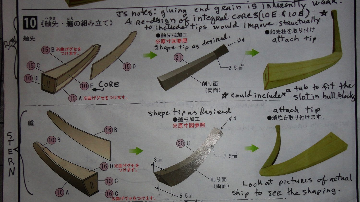
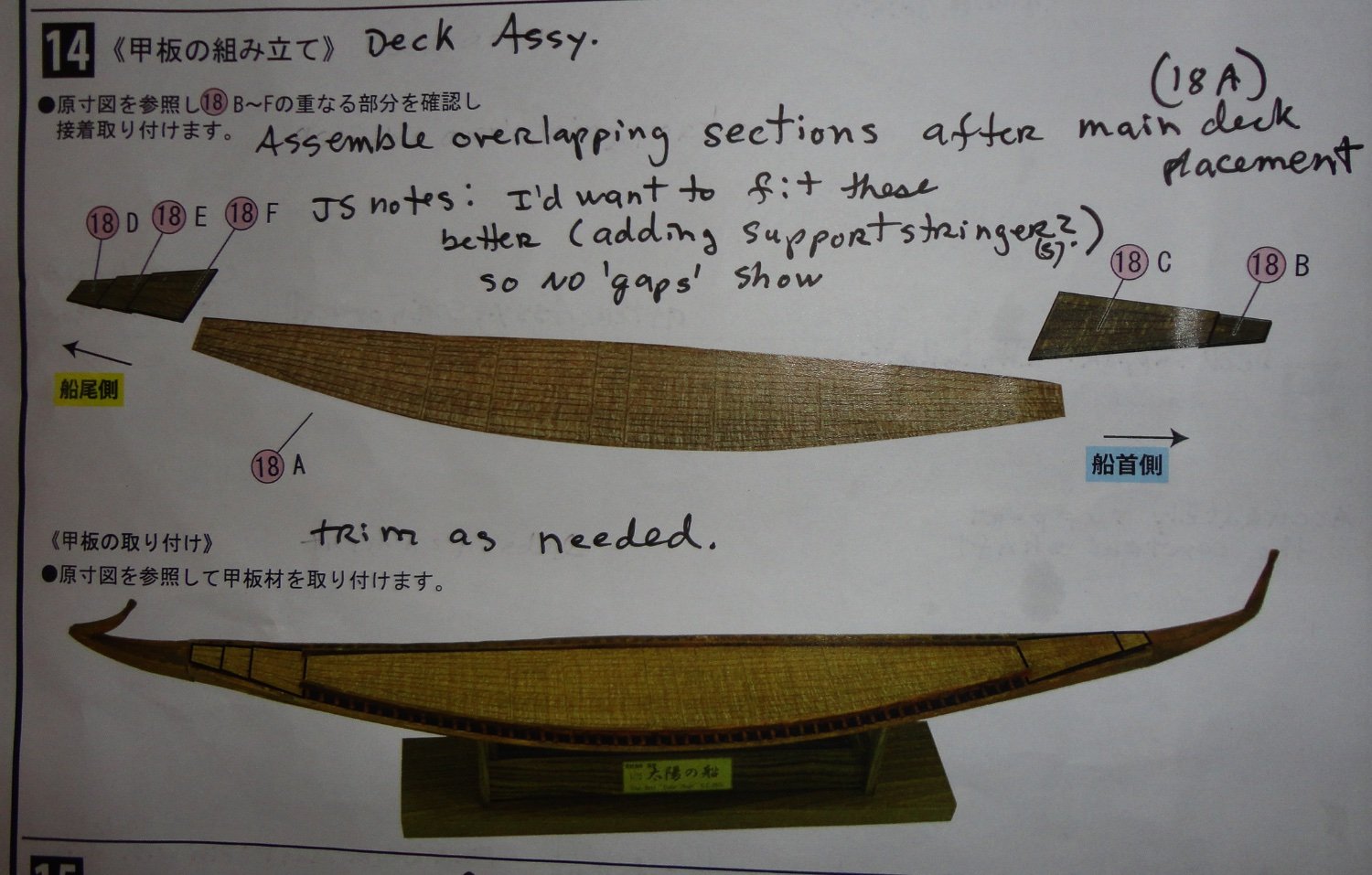
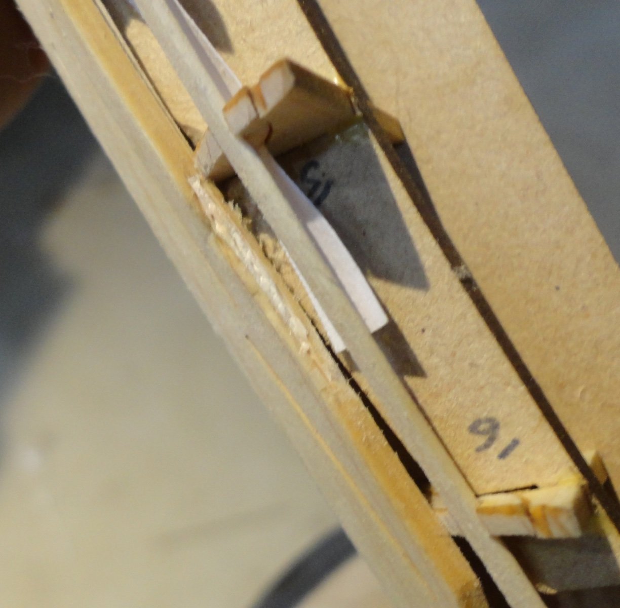
'Had a couple days to ponder some additional work AND some changes to the assembly order ... there were just a couple things that didn't 'add up', and sometimes it pays to think of a build as a 'chess game' - where one needs to be thinking several moves ahead to avoid trouble. Step 8 (not pictured) merely instructs the removal of the 'central keels' at both ends, which was easy since there was no glue holding them back. The 'safety notching' made earlier prevented trouble. Then step 8 instructs to wiggle the outer portions of each frame (bulkhead not attached to the ribs) to remove before taking out the side 'keels'. Below is a photo of this process. This was easy, and the next photo shows the hull after the pieces were snapped off and the keels removed. Then the middle portions of the bulkheads came away easily, and were set aside in a bag, since there are little supports contained in each corresponding to the middle of the rib they will have to be glued to - and they will support the under beam for the main deck cross beams. Since I took time to fair the ribs and stringers, there is pretty good contact (cemented) to the planking, and the hull seems to have a lot of strength - resisting torquing ... of course there is always a limit and I made sure to only apply enough pressure to test the structure. So far so good. Step 9 (not shown) instructs the supports of the central deck beam to be installed ... but it seems best to hold-off on that for a couple of reasons. a.) there is some adjustment work to be done yet, and b.) they will be very vulnerable to breakage and may also make tinting the interior of the hull more difficult. I will show step 10, which appears straightforward. But "there's the rub" (quoth Lady MacBeth). The lower part of step 10 has one face-glue the ends (a weak sort of joint) to the hull, with the projections already having been face-glued. Then the end blocks are to be trimmed 'as needed'. To what angle, I ask - and how is this to be determined? I have to jump ahead to step 14 to get a clue. 'Sorry that this picture is dark, butter the main deck beams are constructed AND the main deck installed, there are additional sections (removable on the original ship for access below .. guess they are equivalent to 'hatches'.) Two are fore and three aft. The first fore and aft fit into the longitudinal beams holding the deck support beams (widthwise) and are supposed to angle upward. The next pieces are 'bridged' between that first piece and the respective end block. I've seen photos of completed kits where they just don't look right compared to the original (or the large-scale model in the Egyptian museum). To make a long story short, I'll choose the the following sub steps to arrive at a solution: a.) Tint the hull interior with a water-based colorant. Then assemble the internal vertical supports for the center deck beam and touch them up with colorant. Rough mate the bow and stern end pieces to fit together at the faces. b.) Assemble the deck support beams. c.) Test fit the beam assembly into the hull, and add the first fore and aft deck hatches to see what angle they need to rise within the hull. I want to have a cross support member at the end of these parts. Then the bow block can be angled so the second (forward) hatch can lie properly - bridging the gap without rising above the planking. The stern has two additional hatches to bridge the gap (the end pair will be glued together for the purpose of getting the angle of the stern block correct. When test fitting is complete, the hatches will be reserved and the deck beams removed. d.) A filler piece will be made to fit the slots of the end blocks, and a hole drilled to accept a small screw before the slot fillers are glued in place. Additional wood will be added to fill the voids of the end pieces before they are covered by the side panels. I'll try and have a pin to strengthen the small end projections, which otherwise seem especially vulnerable. e.)The ends will be glued and the screw will provide the 'clamping pressure' between the end blocks and their mating pieces. Putting blue tape at the edges of the joint pieces will prevent squeeze-out glue from getting on the exterior of the planking at the join. f.) The deck beams are tinted where they will show, then the deck beam assembly is added and glued to the hull. The deck is added, then the hatches - and they can be tinted. f.) Once cured, the exterior of the hull can be faired as suitable - then tinted as desired. 'Sounds like a plan mates, so we'll see. Step a.) begins in then photo below.


- 63 replies
-
- 6
-
-
- Finished
- Khufus Solar Boat
- (and 1 more)
-
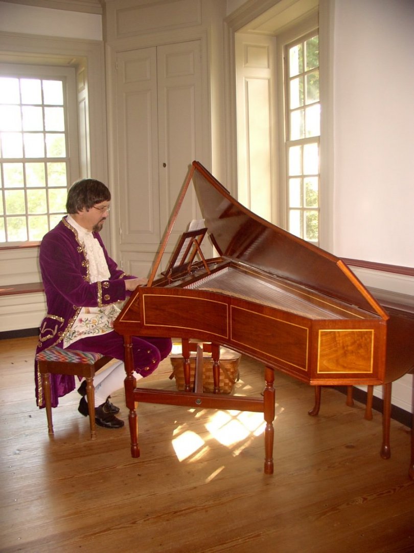
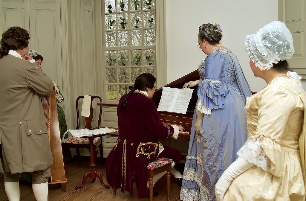
Only a few (maybe 4) needed narrowing from being cut too wide. I built the Baker Harris English bent side spinet from Hubbard Harpsichords (one time kit supplier) between 1985 and 1987. I took extra care with the veneered parts, even veneering the back and bottom of the instrument. The keyboard transposes (my kit bust), but due to the geometry of the instrument (as opposed to a 'regular' harpsichord) the transposition is an entire step (note). The idea was to tune at A 440 (modern pitch) and transpose for period pitch (A 415), but a full step is way too much (lower) and one loses notes at the top and bottom of the keyboard when transposing (not that those are used very much). Lowering string tension much below 90% of breaking strength 'muddies' the tones produced ... instruments should produce a clear sound - with steel having more of a 'ping' in the treble, and brass having a mellow sound. Phosphor bronze is another matter. Since building, I've hauled it in a padded case to several historic (Colonial) sites in the area to perform for special tours, and also play for English Country dancers. These days it stays put at home. The string scaling 'as built' is identical with an original from the Baker Harris shop (London) that the Connecticut owners allowed Hubbard to copy in return for restorative work. Brass stringing (intended for the instrument) breaks a lot in the middle range at modern pitch. My conclusion is that the problem is a combination of period pitch being lower AND that period brass had more impurities - giving it a higher tensile strength. I devised a second inner 'nut' (paired with the bridge on the soundboard, the string length is determined) for the middle portion of the scaling that adjusts the string lengths (shortening slightly) so that they can sound at about 90% of breaking strength at modern pitch ... they rarely break , yet provide good sound at A 440.
- 63 replies
-
- 7
-
-
- Finished
- Khufus Solar Boat
- (and 1 more)
-
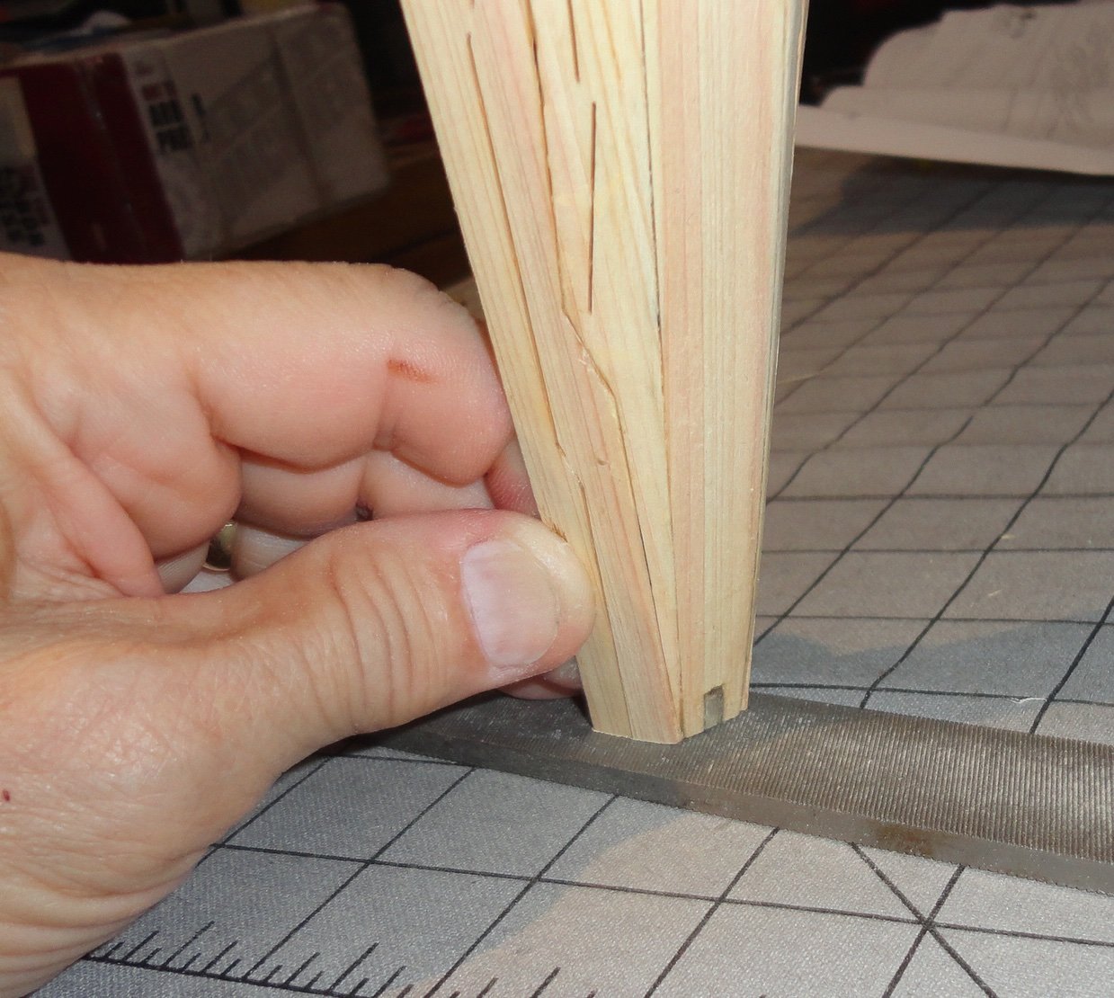
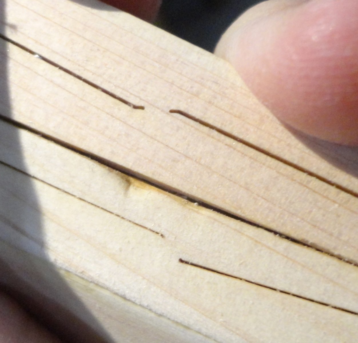
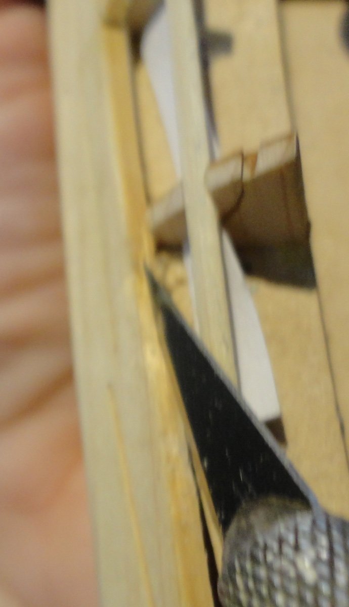
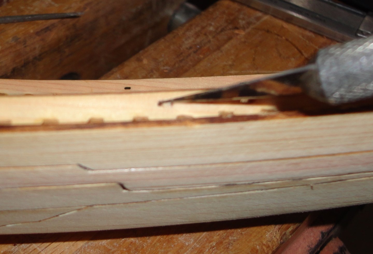
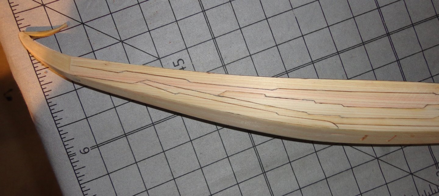
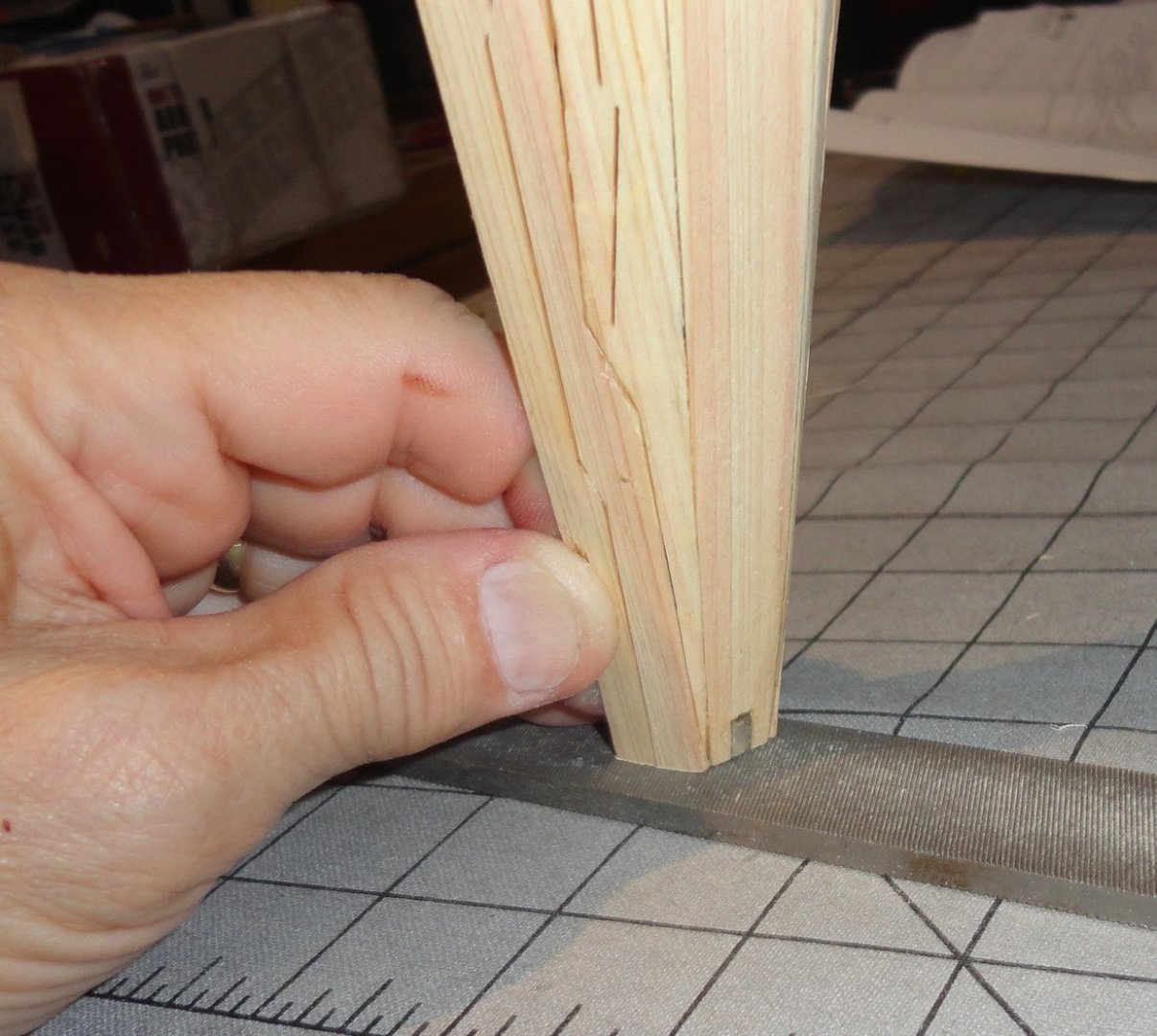
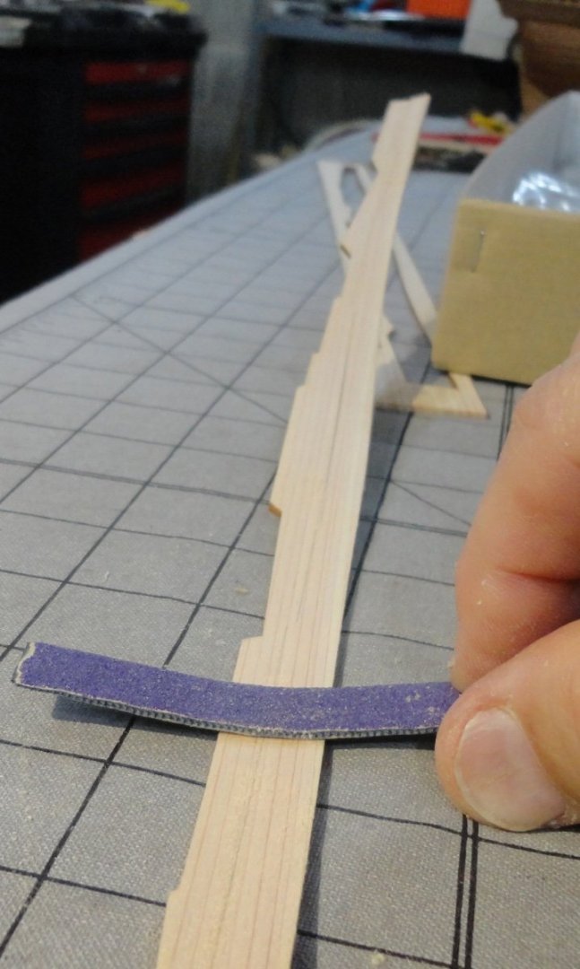
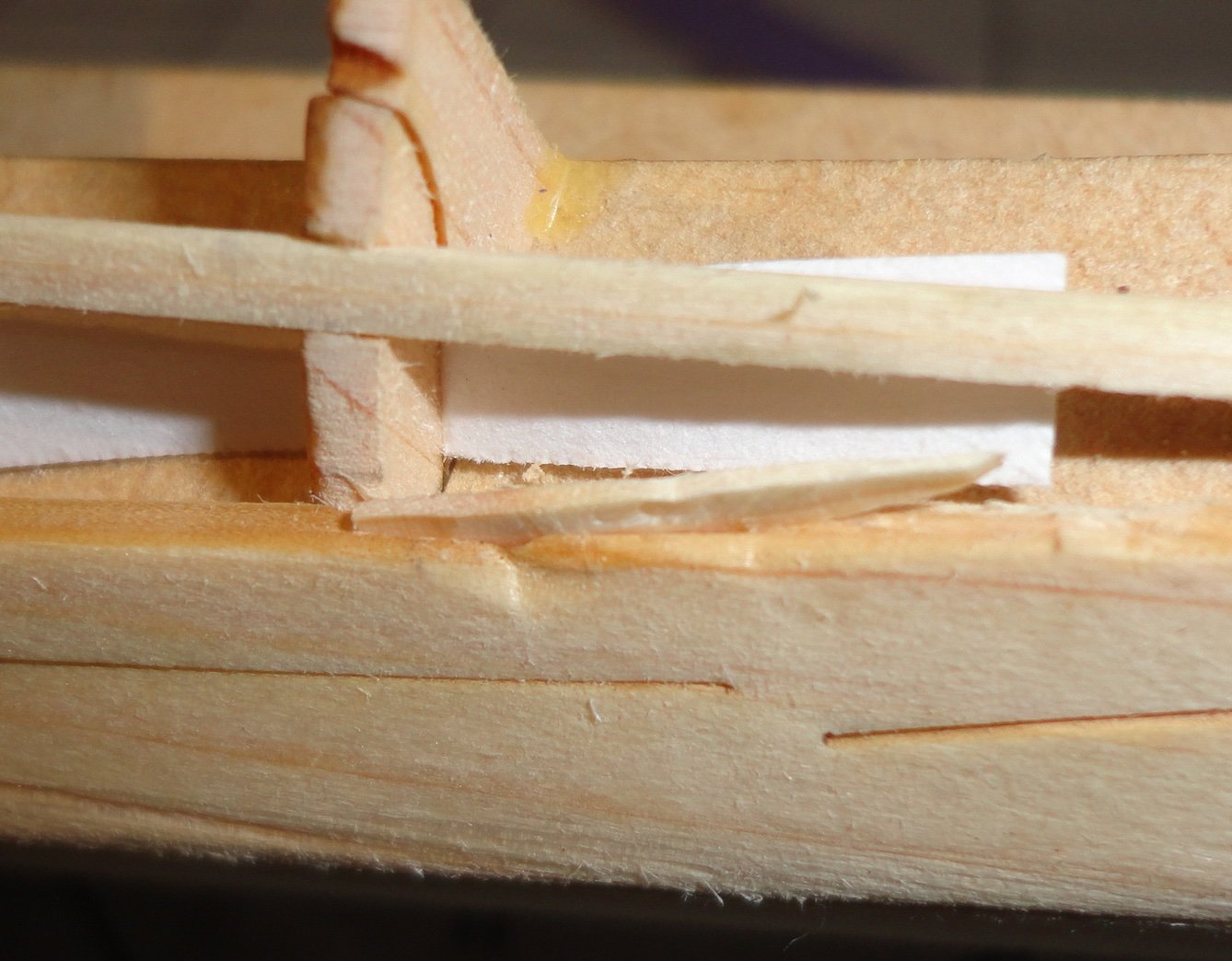
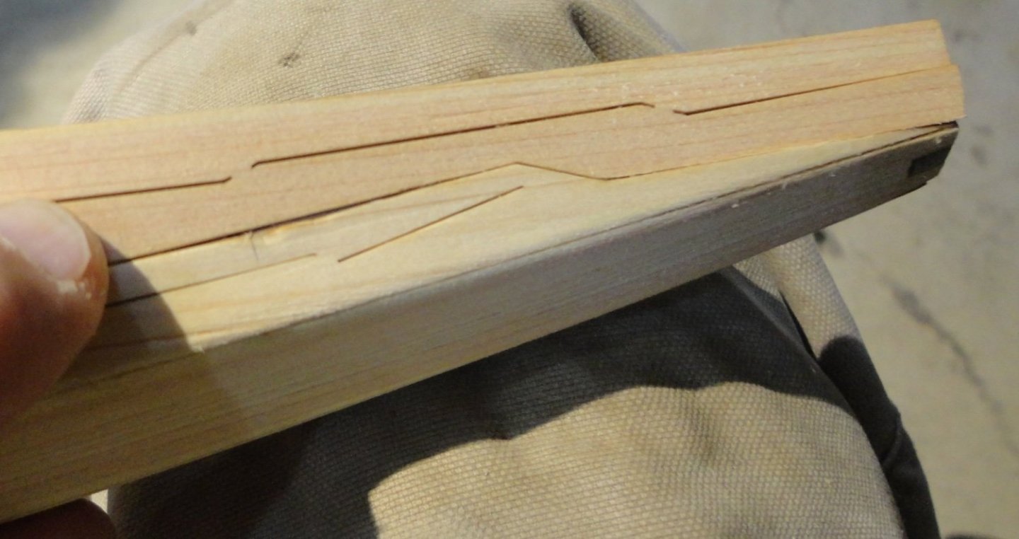
The last planks, though dry on the surface, still retain some moisture inside that might take a couple days to fully dry out. Thats OK since they can still be bend to adjust as needed. These planks needed just a little sanding/trimming of the edge angle to fit well with the planks already in place. I also found that (since they are on the wide side - having two planks conjoined) I could use my sandpaper covered hacksaw blade (bend just a little more) to give the inside of each plank a slightly concave profile to better fit to the ribs. They still need a little bending as well. I found one place where I'damaged a plank ... don't know if it was with a clamp as the planks are a softwood, or by some other mistake. I'm still fitting the last plank, so it's edge angle is not finished - but I was concerned that the damage to the mating plank would not show well on the model. Then I recalled a technique I used some time ago when building a harpsichord, and needed to adjust some of the mortices on the keys where the mortice I made to accommodate the locating pins (and allow travel also) were a little too wide. The manual suggested making a fine cut with an X-acto next to the mortice and inserting a tapered sliver of basswood (the keys were basswood) into the cut. Then the side of the mortice would move outward to reduce the width of the mortice (and then try to work the pin and adjust as needed). It's easy to remove wood, but tricky to put it back. Since I didn't want to glue a piece in and have the edges of the patch show, I tried the above method. Step 1 is to make a cautious cut into the edge of the plank. Pardon my focus, but I was holding the workpiece with one hand and the camera with the other while trying not to have the knife fall out. The next picture shows the wood slivered (tapered at the ends and bottom - made from a piece of stringer stock, part #28) just started to be pushed into the knife cut in the edge of the plank. Then I pushed (without glue) the sliver into the cut with the butt end of a round file, and then the pointy end. It did expand the plank thickness in the affected area, which will allow a little sanding later to make flush (but not so much as to expose the wood sliver. Now with a little adjustment made to both planks, it looks a lot better and should clean-up later after gluing.


- 63 replies
-
- 9
-
-
-
- Finished
- Khufus Solar Boat
- (and 1 more)
-
Ahoy Daniel ! One can see a number of approaches in the various builds in the Forum. One builder used black crayon sparingly on the edges, which did not 'soak in' at all. After decking excess seemed to clean up OK with some scraping/sanding. That having been said, I want to use the black thread method on all the joins (including the ends) the next time I plank a deck. The thread should not be too thick, and the picture you posted looks fine. My guess is that using a small wood scraper (sparingly) will not produce the fine dust that sanding can make. If sanding dust gets in the small gap between the planks, it might take s very fine brass coat brush to help get the particles out ... or with blasts of compressed air. If 'Dust Off' doesn't work, that of an air compressor should. Whatever method you want to try, doing test piece with a number of planks (they don't have to be good modeling wood) is highly recommended. You can then judge the results for yourself.
- 5 replies
-
- 2
-
-
- Polaris
- first build
- (and 1 more)
-
Ahoy mates ! I found that bending the middle strakes for each side was easy, and I modified the method as follows: Run hot tap water over the piece as before, then (once half-soaked) I moved the strake back and forth over the gas burner flame ... almost right on the flame (there is a danger of scorching if the wood goes dry on the surface) and it will become almost too hot to hold (but not quite) and the wood will give off steam. Then it bends easily, but I used both hands with the fingers positioned on the outside of the bend and the thumbs on the inside as a 'human mandrel'. One has to have the 'feel' of how far to push it, but the Japanese Cedar is generally compliant. Since wet wood doesn't sand very well (raises fibers like crazy), I let it dry a bit first. It fit into position like a glove and there was no adjustment needed on the angle where the edges going with the garboard strakes. Glue was applied and I kept using blue painter's tape, with clamps on one end where it needed a little more than tape. Left and right were glued and allowed to dry together. Some observations: Titebond glue (aliphatic resin) once past the 'grab' stage will go into a 'soft set' (something like 30 minutes). There is still pliability at this time, and some positional adjustments or re-clamping can be done then. A wood part can be pried off still without too much trouble to re-position after 'refreshing' with a little new glue. After 1 - 2 hours it has what I might call a medium cure, and the parts can be sanded/trimmed with care. If something slipped while setting, the isopropyl alcohol removal method (see earlier in this build) will work quickly and effectively. A 'hard cure' takes several hours. When removing blue tape, do so gradually (and at a 'low angle' to the plane of the surface) to avoid pulling up wood fibers. I use the tape for painting edges that has no more than a 'medium' stick ... other tapes with more 'stick' should be avoided. Gorilla tape is RIGHT OUT. I bent the final strakes as above and decided to tape them to the frame to set the bend. A view of the interior as the planks dry. Once dry I removed the tape (except in the middle so the planks would not fall off), and they had very little spring-back. This may be because I worked them good per the 'wet wood over flame' method described above. They were over bent a little so allow for spring-back. Obviously there is some, but noting to fret over. I have to get into scrubs for an evening shift at the hospital, so I'll post more on planking later. Johnny

- 63 replies
-
- 8
-
-
- Finished
- Khufus Solar Boat
- (and 1 more)
-
Rob has offered some good advice, which is pasted from an earlier post in this log: "I just wanted to help those, thinking, or beginning rigging on their own models. 3 things I want to leave you....1: Use the appropriate size cable for your rigging (Smaller is better). 2: Use the appropriate color, Greyish tan is best, (deadeye lanyards are NOT running rigging...stop using tan cord) 3: Rig as much as you are comfortable with(but if you put that much effort into your hull build...why stop there, challenge yourself, you'll be a better modeler because of it)." In perusing a number of logs, the ones who make use of what can be considered 'miniature rope' for their rigging (made on a mini rope-walk such as Chuck's rope rocket, or purchased from a vendor using similar techniques) look the best. There is very little rigging 'fuzz' - which shows up on close shots, and must be visible on a close examination of the model. Some kit rope isn't too bad and can be treated to reduce 'fuzz', but given the effort (and cost) that goes into a build, why not make the most of rigging opportunities - as rigging is often 'half the model'.
- 3,560 replies
-
- 2
-
-
- clipper
- hull model
- (and 2 more)