


Dan Vadas
-
Posts
3,261 -
Joined
-
Last visited
Content Type
Profiles
Forums
Gallery
Events
Posts posted by Dan Vadas
-
-
5 hours ago, Backer said:
too long is not a problem.
you can bend the tracks a little down between the return rollers.This calls "a sagging look" i think.
The tracks were actually TWO segments too long, far too long to compensate for by "sagging". No problem, it's already fixed
") :
:
You'll notice that one roller has come adrift, easily fixed
") .
.
Danny
- gjdale, popeye the sailor, hof00 and 9 others
-
 12
12
-
13 hours ago, vossiewulf said:
the winterketten track extensions on your track should bend inward toward the bogies a bit.
That's easily done after the tracks are installed.
3 hours ago, Backer said:The track tension is controlled with the idler wheel.
Unfortunately the idler wheel is the first one I need to glue to the track. The lugs are too tight and there is too much friction to fit it last. I found out the hard way that the tracks are one segment too long - a bit of cutting and re-gluing coming up.
Danny
-
Thank you all for the comments, and especially vossiewulf for the extra information
.
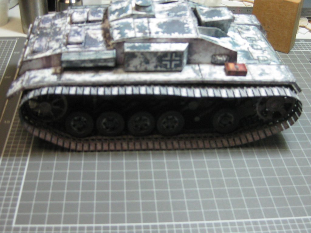
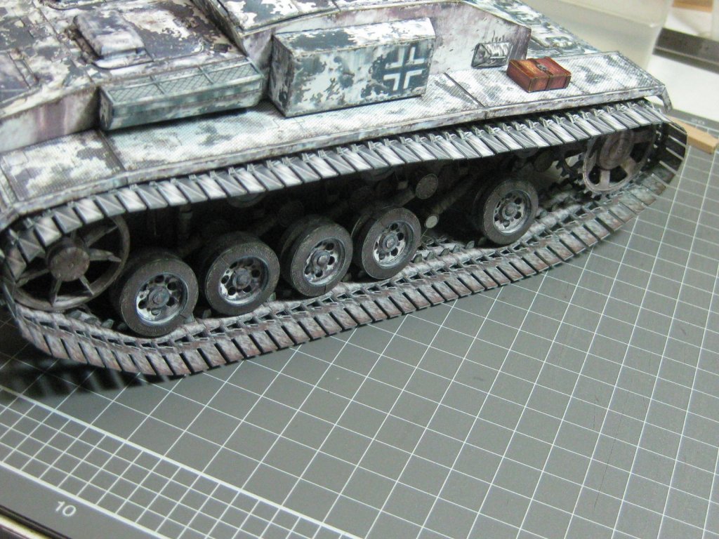
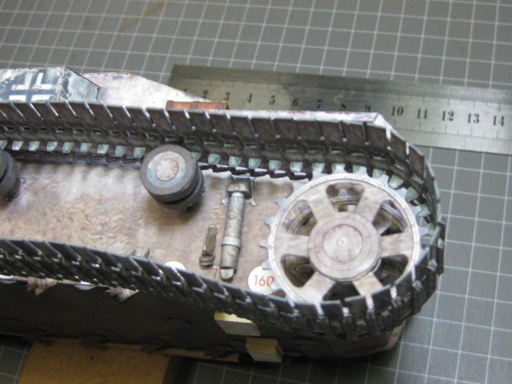
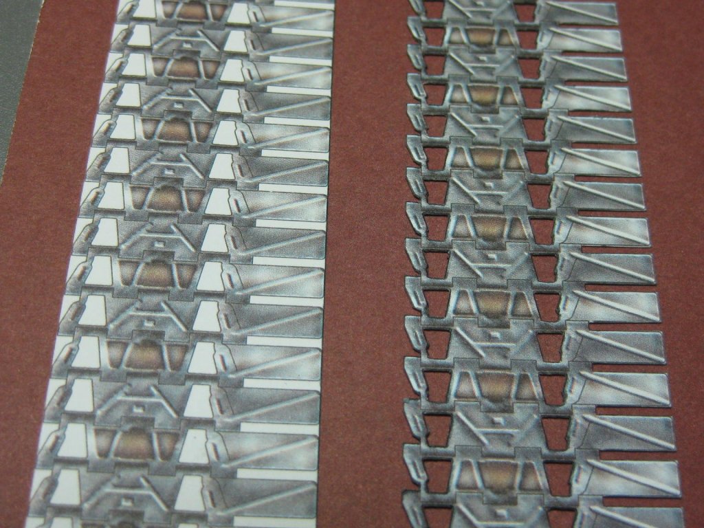
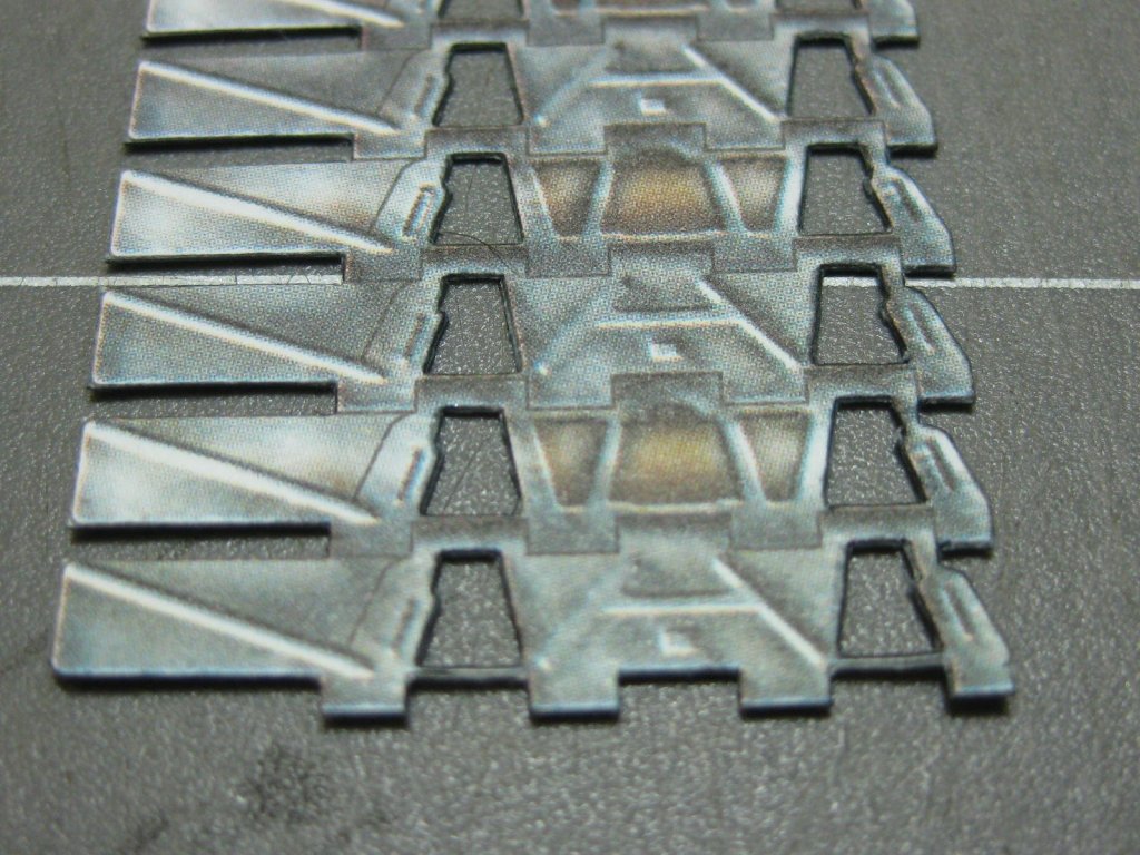
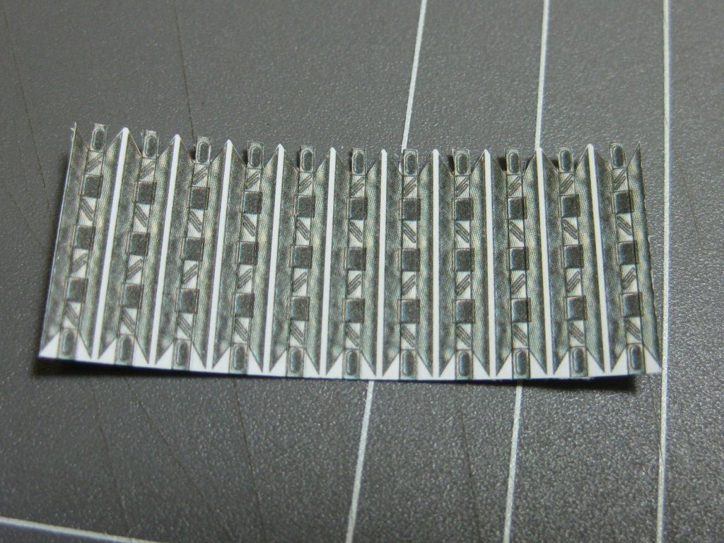
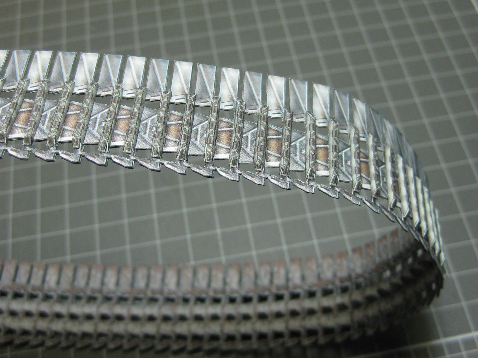
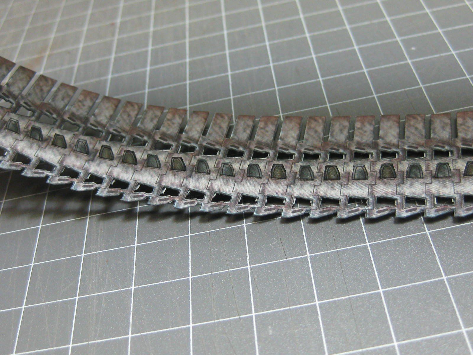
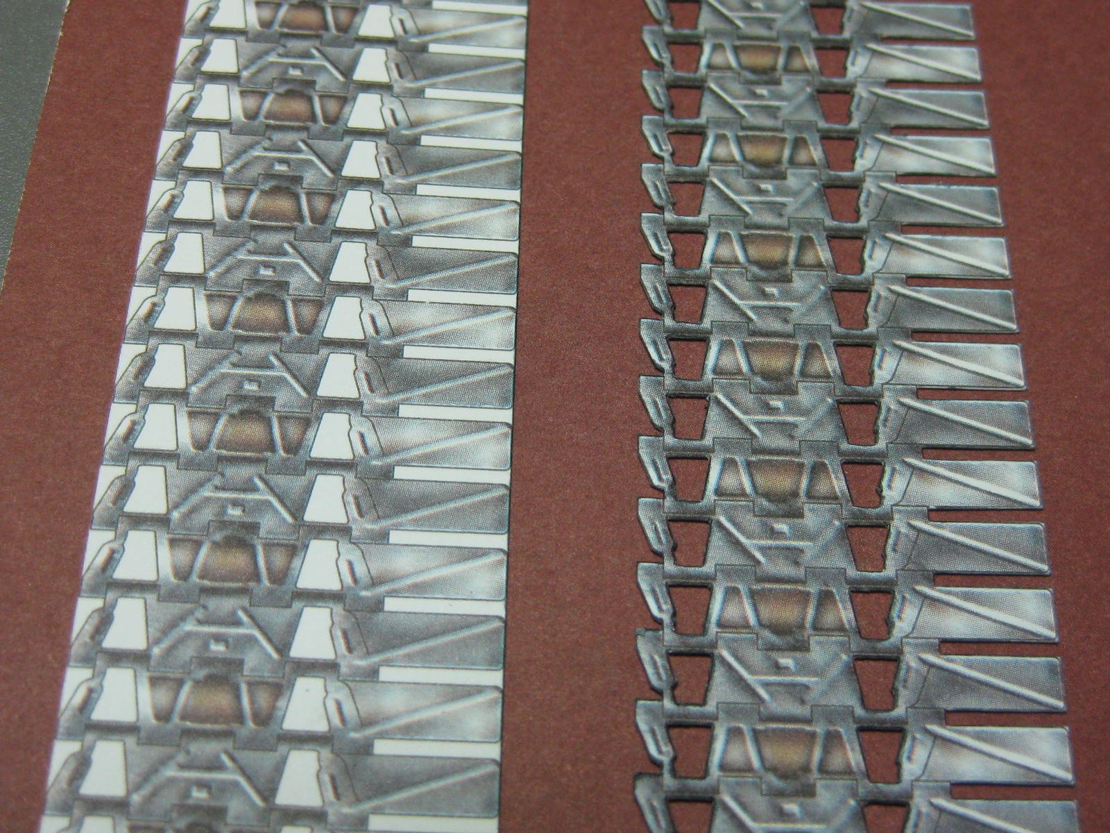
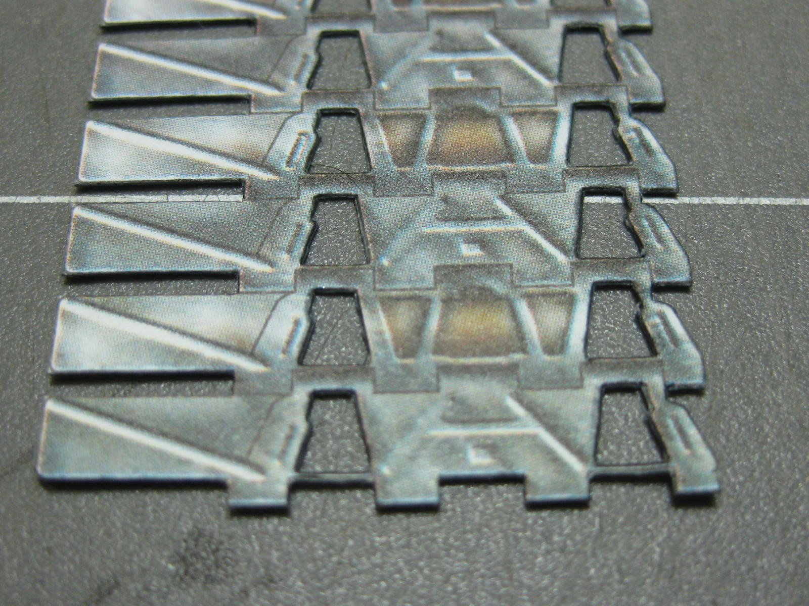
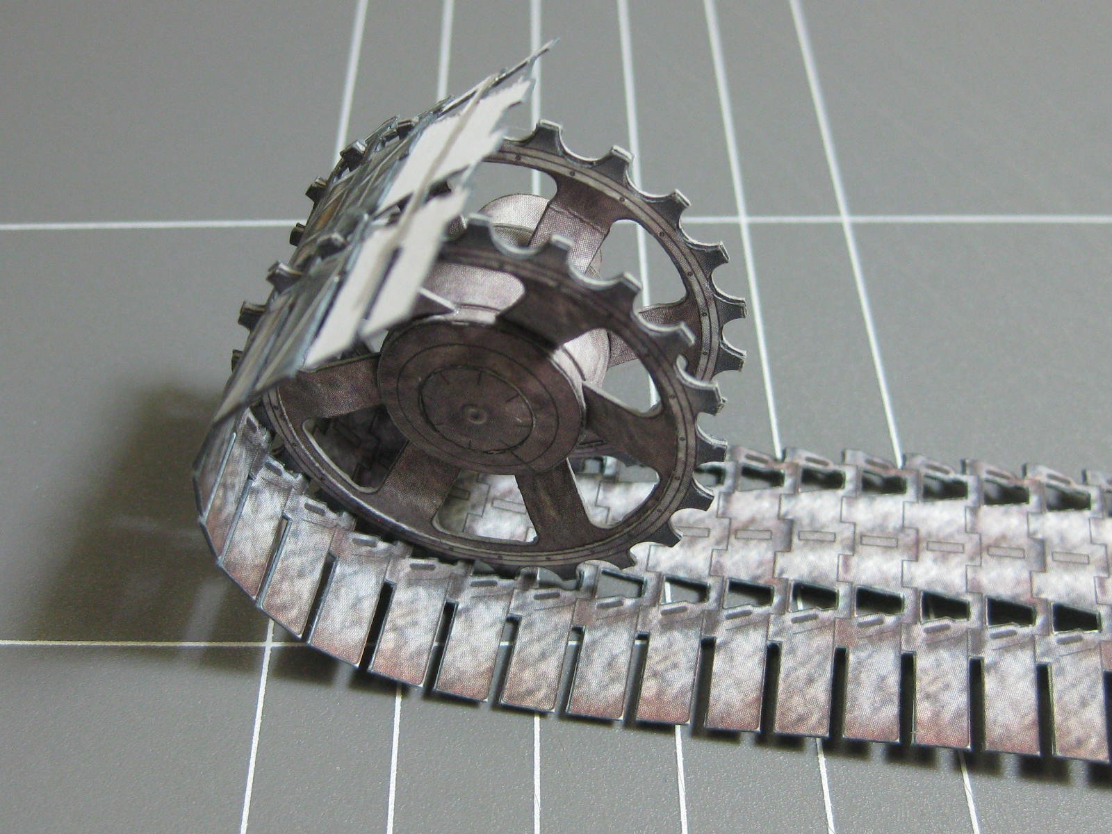
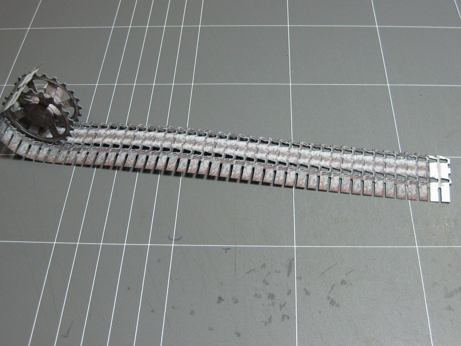
I have finally finished gluing up both sets of tracks. That was quite a marathon
. Below are some details of the "teeth" and "lugs" :

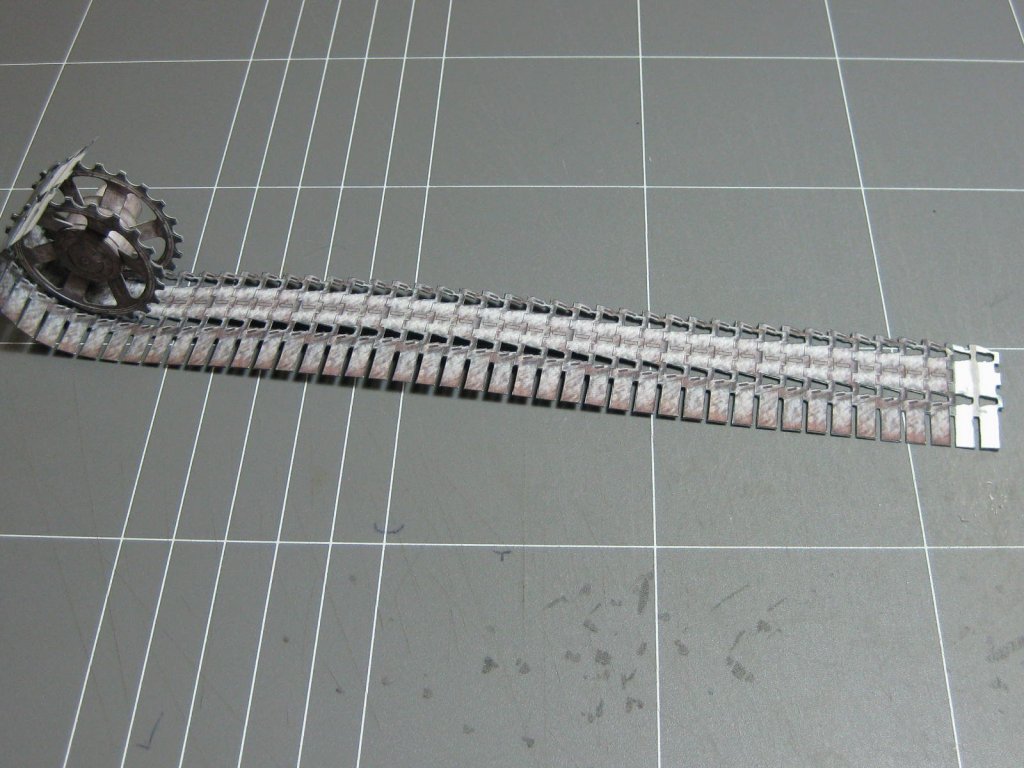
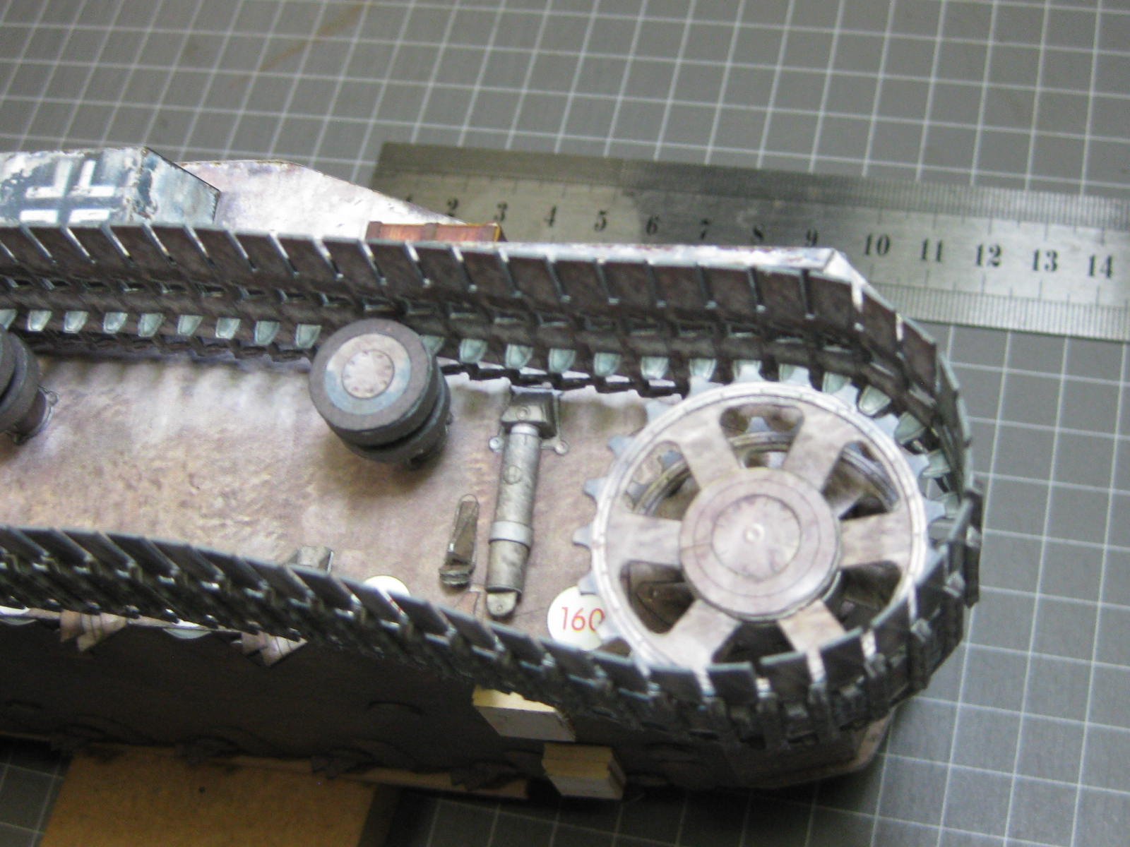
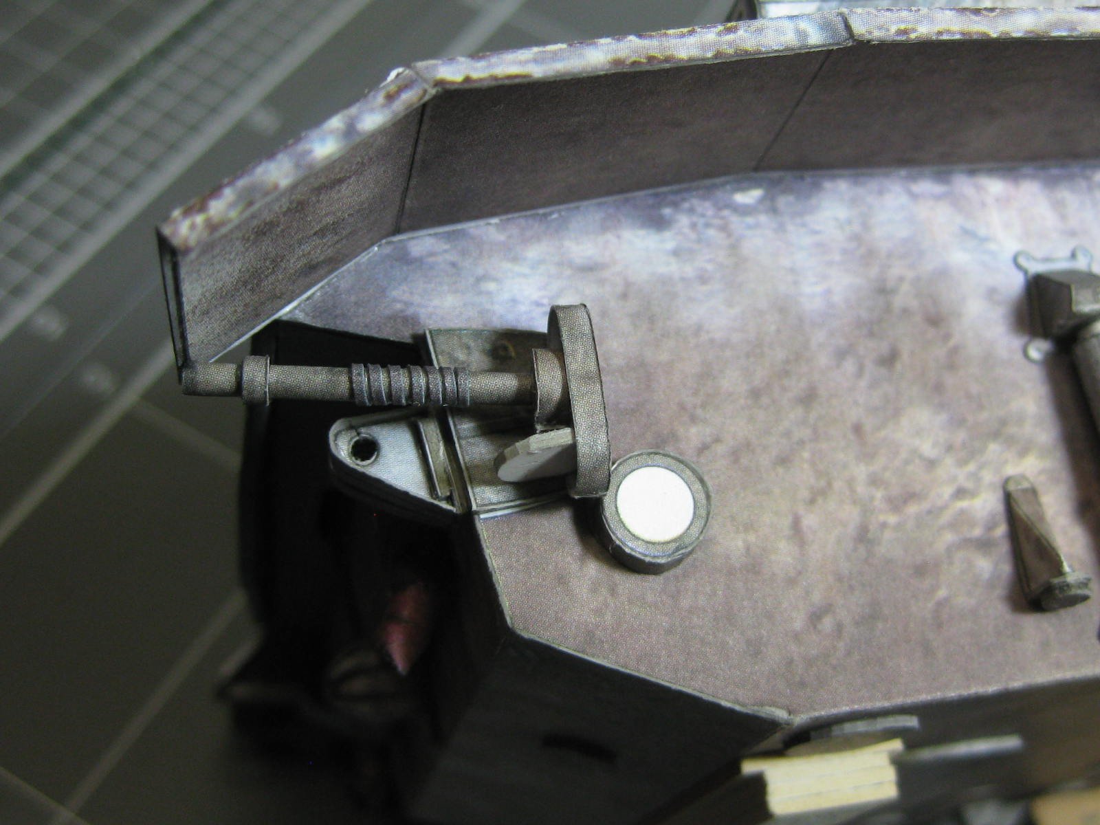
Fitting the tracks to the body isn't easy. I started by first gluing the locating lugs to the idler pulley, and then glued the pulley to the chassis :
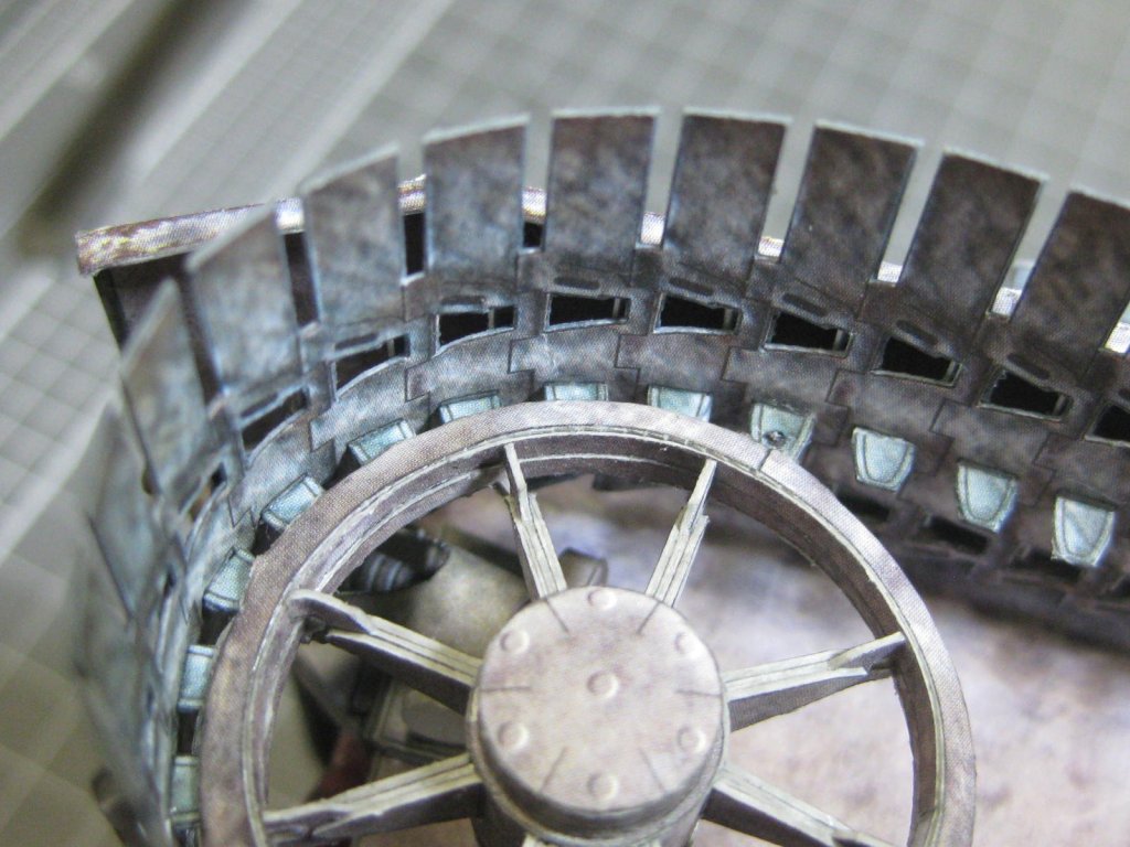
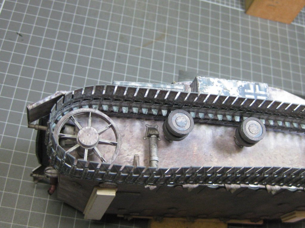
The drive pulley is only glued to the tracks at one point so far, and not glued at all to the top rollers yet. Once the idler pulley has dried I'll glue the drive pulley into place. The bottom rollers will be fitted last to tension the tracks :

Danny
- JohnB40, Canute, GrandpaPhil and 13 others
-
16
-
Sorry Sjors and others who have been waiting for an updated Index. My health and Xmas have been getting in the way a bit lately. The Indexes are now up-to-date.
Please note - updating the Indexes is a rather complex operation. It's not worth the time to update for only one or two new build logs - I usually wait until there are 5 or 6 new ones before updating.
Danny
- BETAQDAVE and Tigersteve
-
2
-
13 hours ago, Captain Slog said:
little will be done on the odd times I get home so likely the next update will be in a years time
Gee I hope not
 . Good to see you back Slog, and excellent work as usual.
re: the 0.2mm wire - where did you get it? I bought the last 2 packs of it that BNA Model World had (way back about 2 years ago) and they have never re-stocked it. I can't seem to find any on the interweb
 .
.
EDIT - never mind, I just checked BNA again and they now have heaps
.
Danny
- Captain Slog, mtaylor, CaptainSteve and 1 other
-
4
-
23 hours ago, amateur said:
The guntowers can be turned and the guns can be elevated. Why you should want to do, I don't know
Because you can
. When you start fitting all the small pieces to the decks around them you'll be glad you can move the barrels out of the way .
Danny
- popeye the sailor, amateur, mtaylor and 4 others
-
7
-
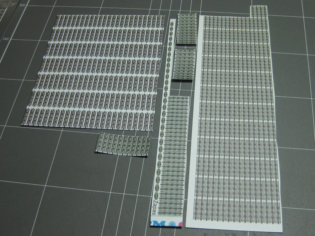
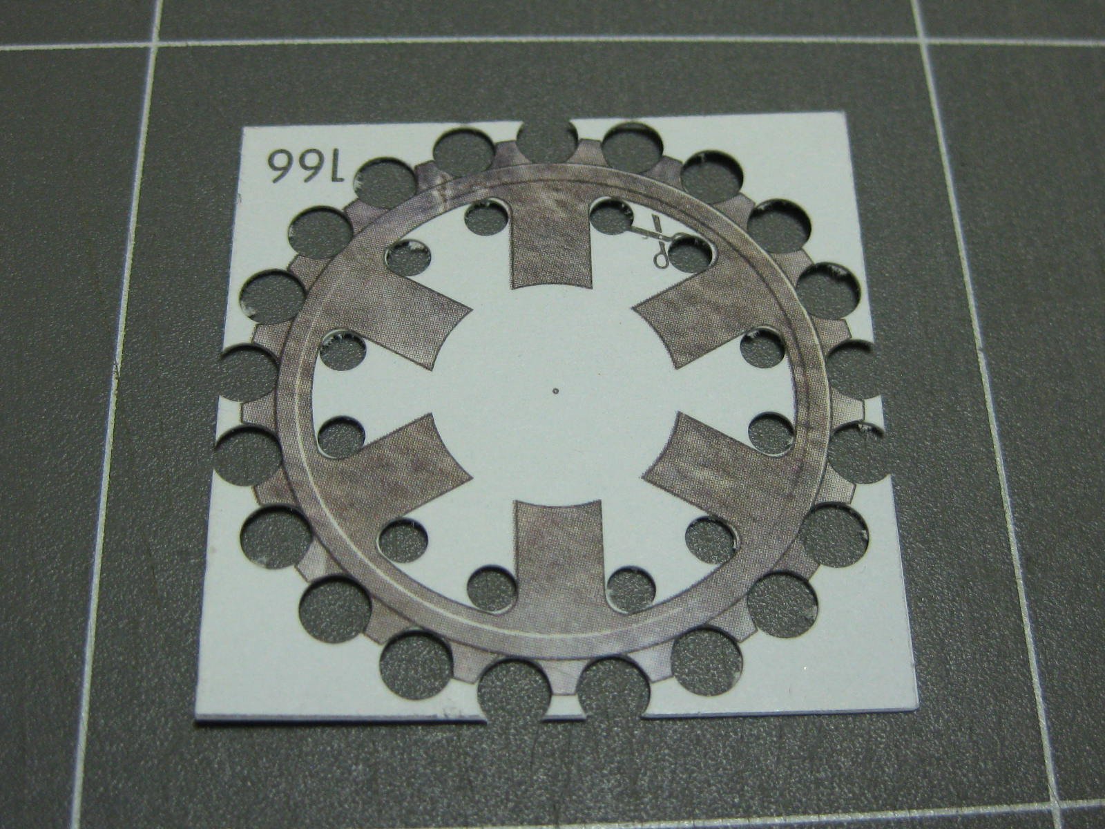
Time to start on the tracks. Here are all the ones needed for them. They come as an inner and an outer :
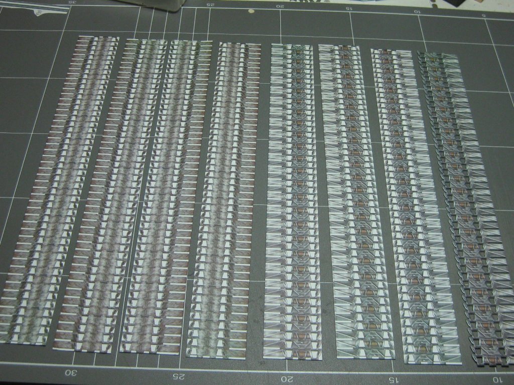
As you can imagine there is a bit of cutting to do :
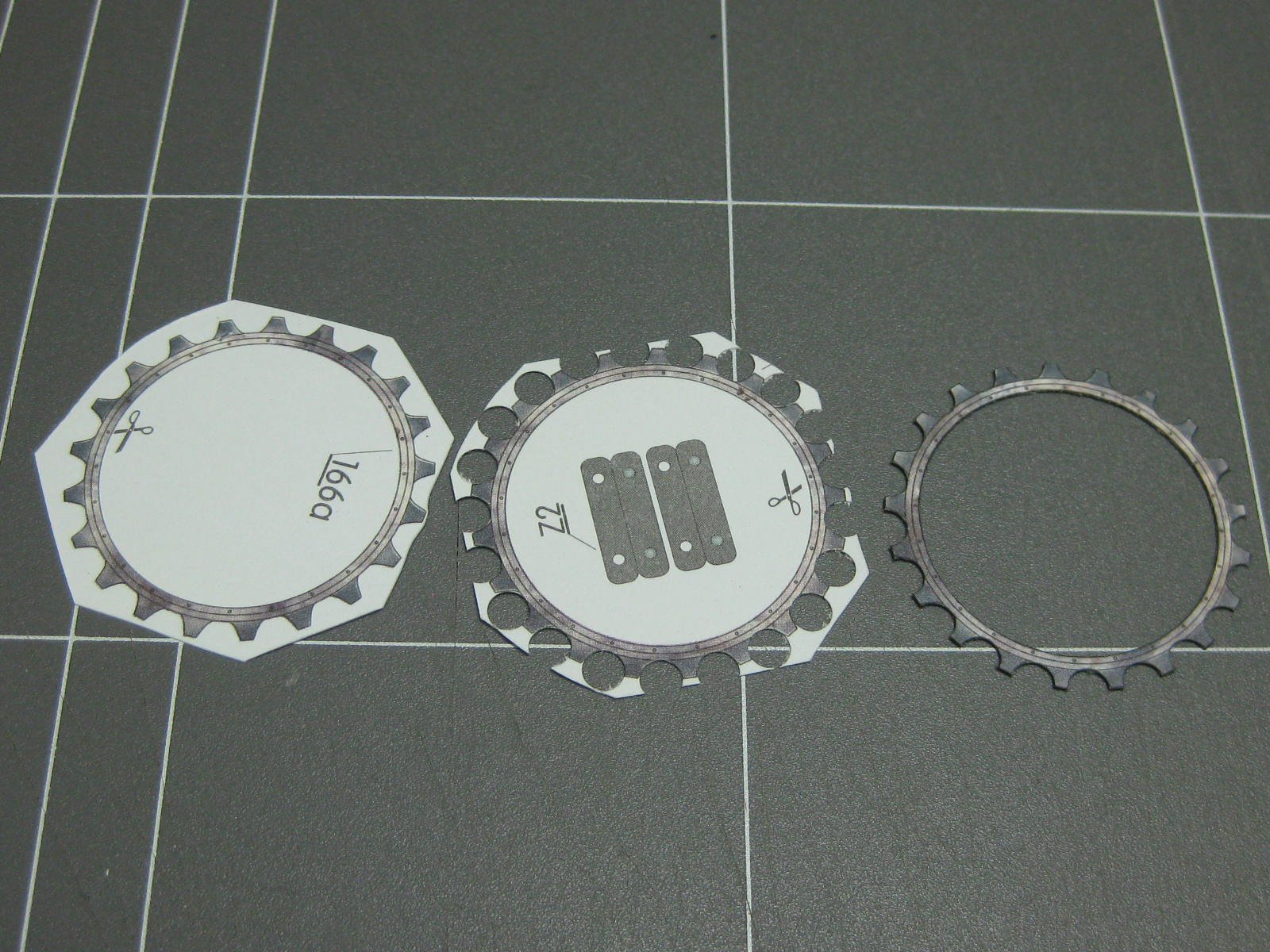
I didn't align the sprockets quite right - the teeth of the inner sprockets don't quite align with the outer sprocket. This one isn't too bad, and I'll probably get away with it, but the other is worse so I'm going to have to cut it apart and fit the sprockets properly :

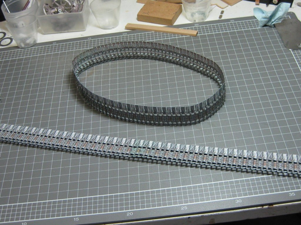
I've overlapped the inner and outer tracks to avoid have a "hard" joint - two sets are needed for each side :
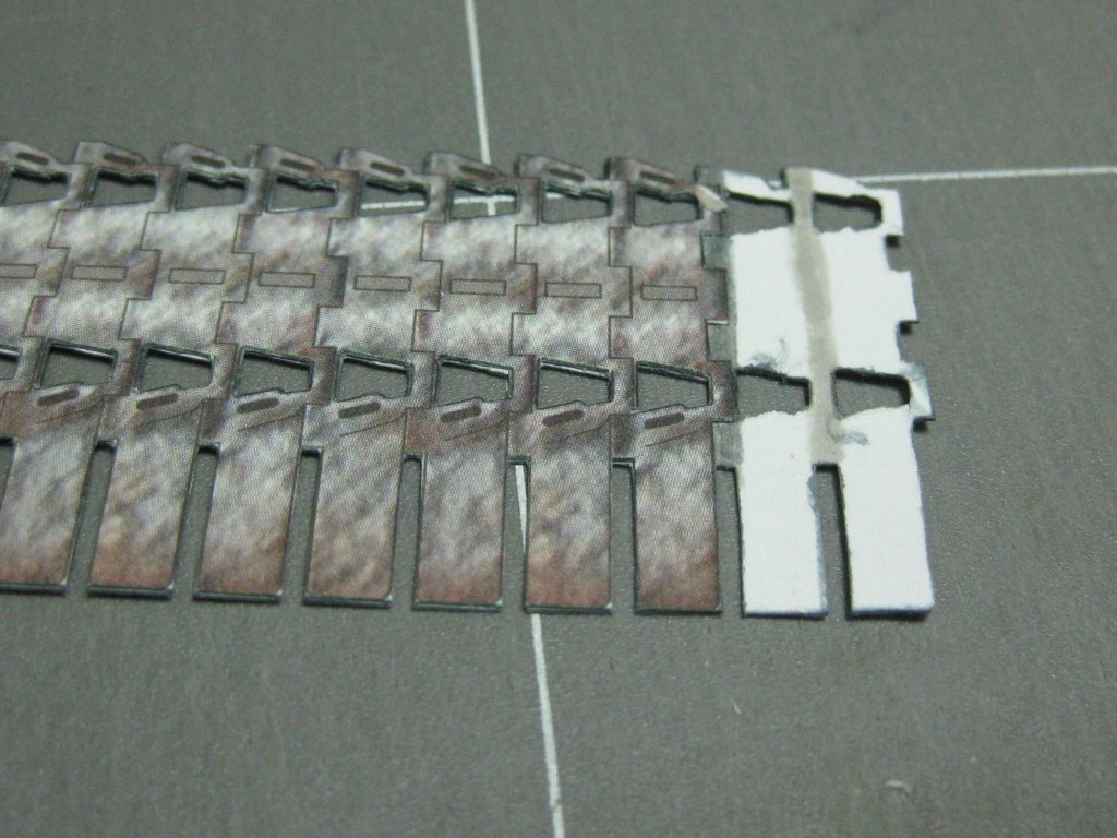
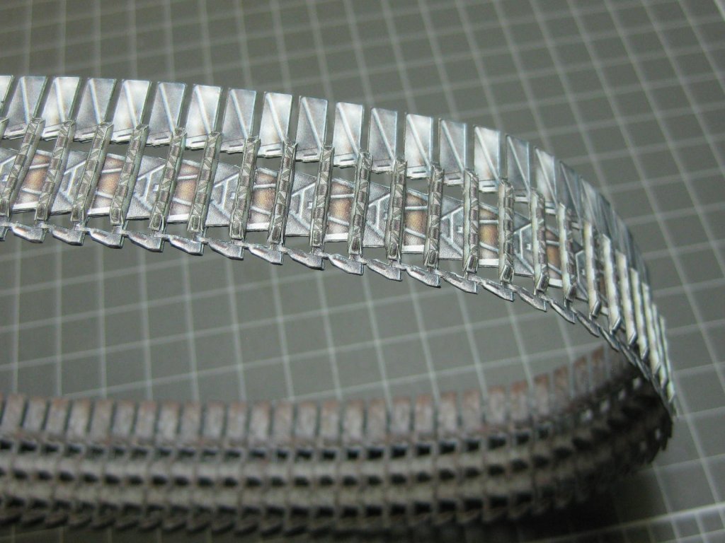
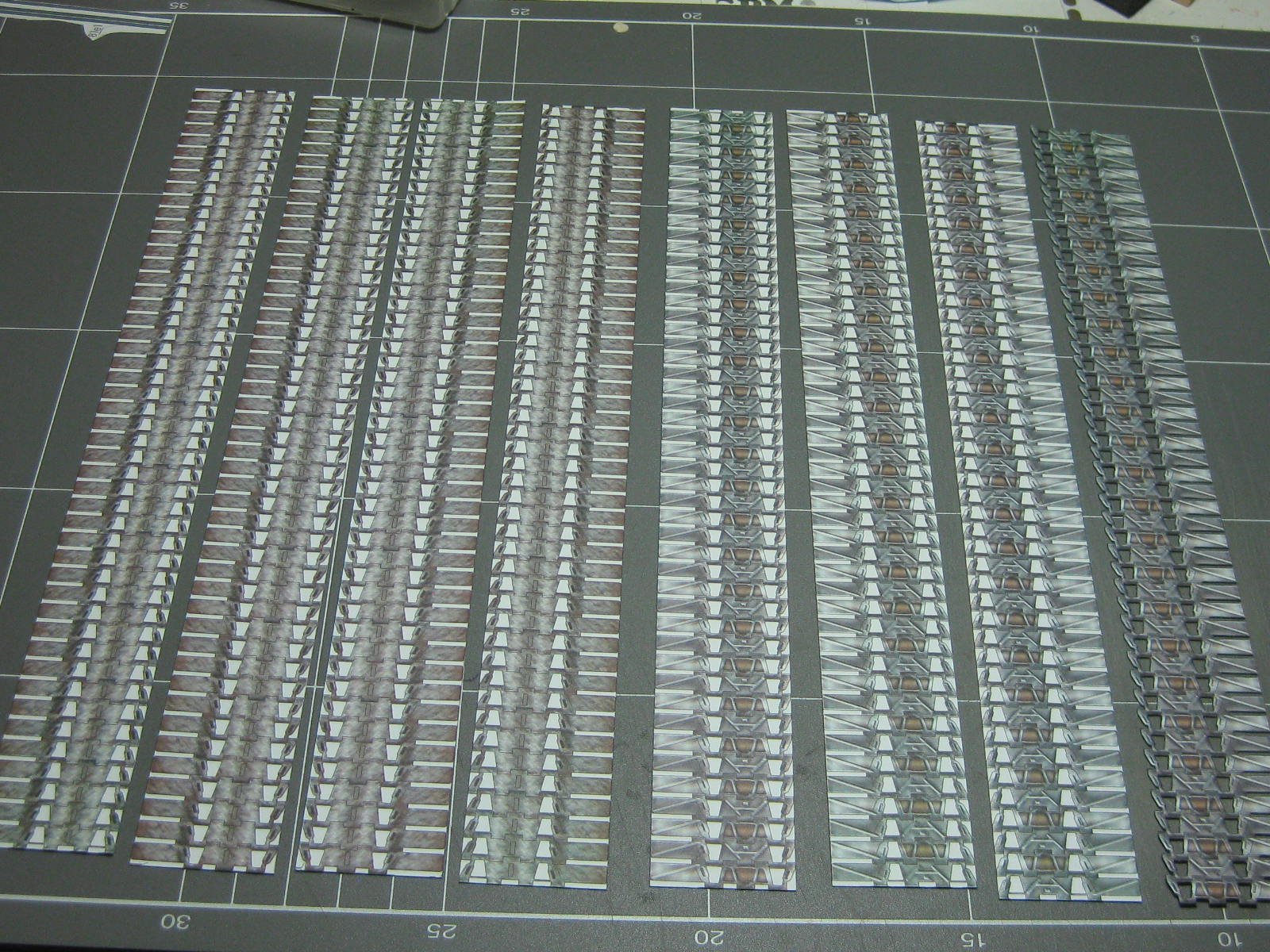
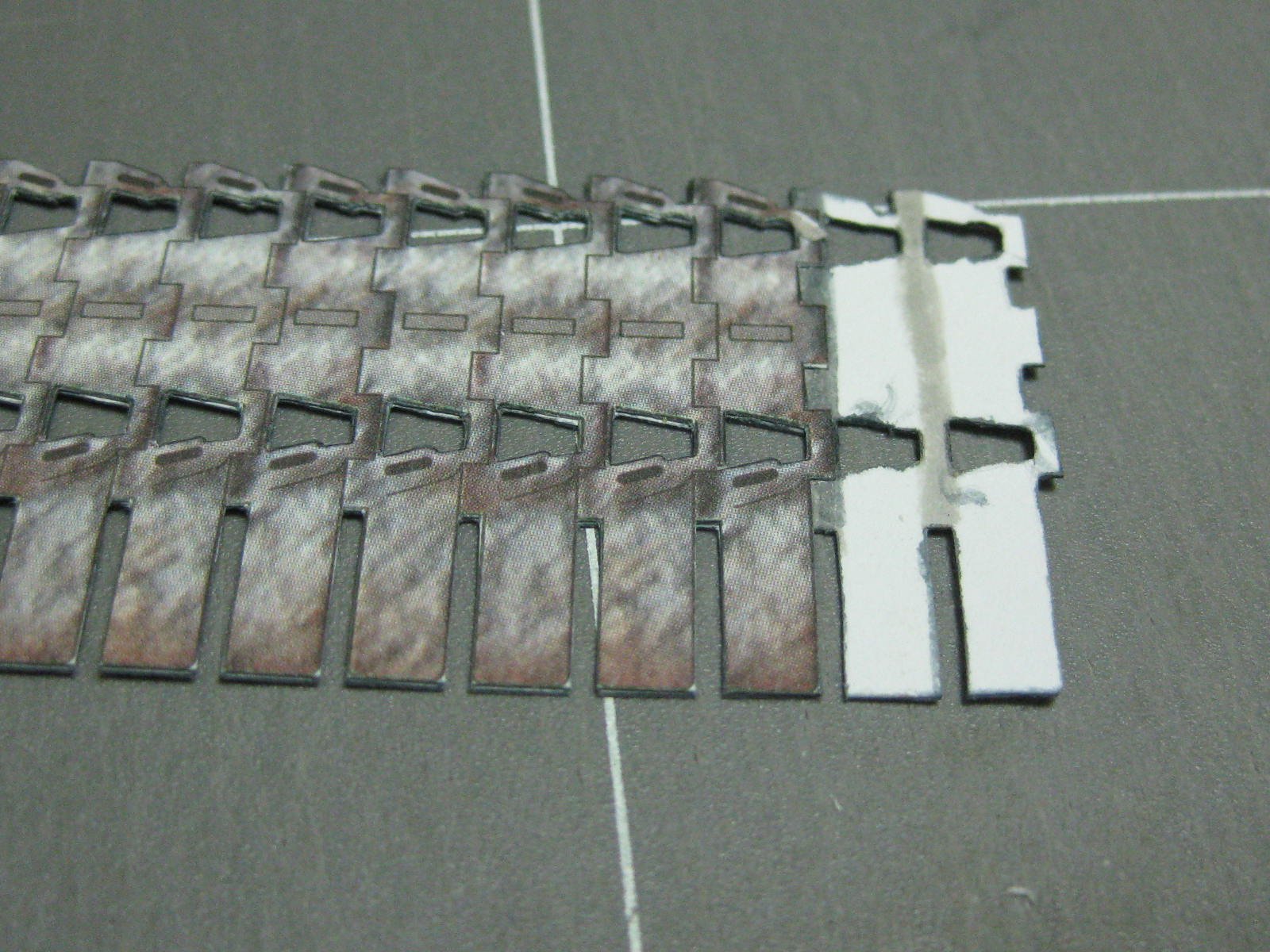
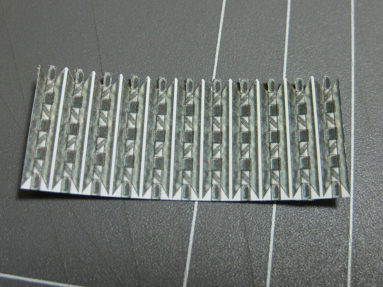
Just when you think the amount of cutting needed can't get much worse - here are the "teeth" of the tracks. One is needed for each track segment :
There are also just as many locating lugs, which fit to the inner track and run between the double rollers.
The kit gives three options for the tracks - a simplified belt without any of the "teeth" or lugs, the option I chose which is a continuous belt with all the details, or the individually segmented tracks.
After looking at doing the tracks as individual "articulated" ones I decided against it. For one thing there are absolutely NO diagrams as to how they go together, although I did eventually work it out. There isn't much point, as the finished articles look identical anyway, and there is a lot more cutting and folding involved. In fact the only instructions regarding the tracks in the kit is one short paragraph listing which tracks go with each option - and they got the whole lot WRONG anyway 🤬.
Danny
-
21 hours ago, druxey said:
Those look very challenging! I hope one can see them when the model is completed. Merry Christmas down under, Dan!
Thanks David, and all the others who replied
.
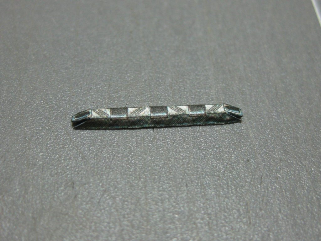
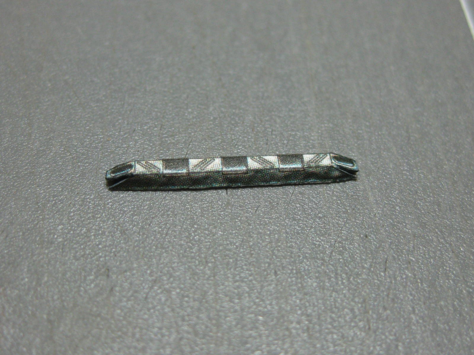
The sprockets are very visible, this part (the tension adjuster) not so much :

I don't think I've got it quite right - the instructions were very vague about it (as usual
).
Danny
-
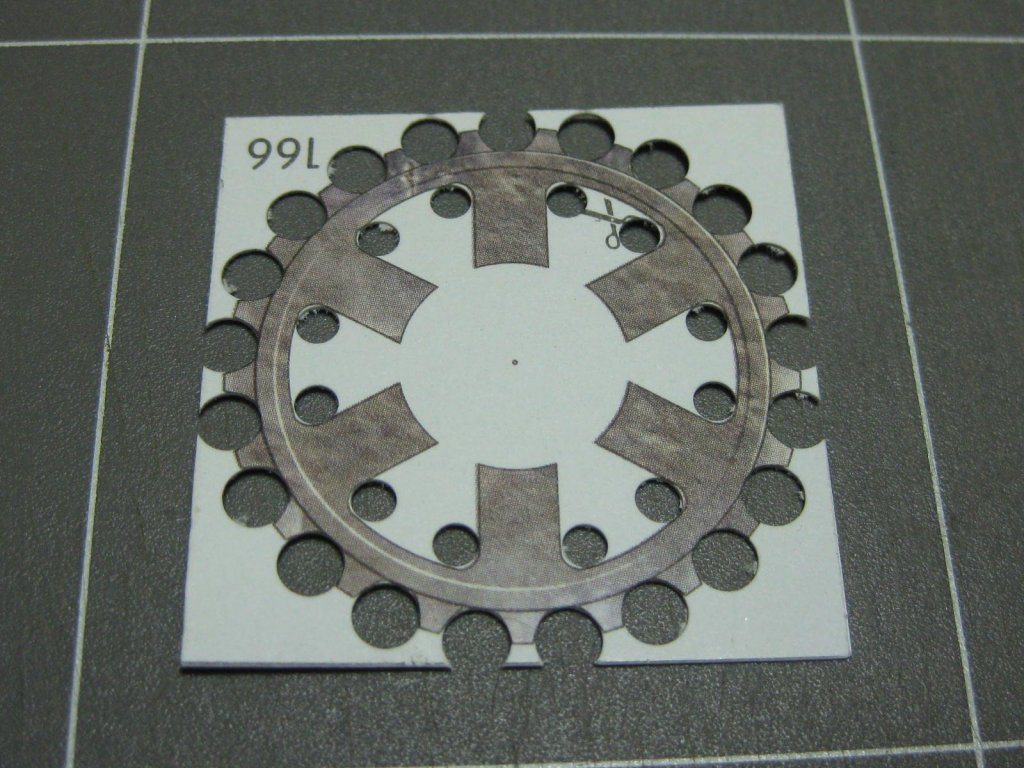
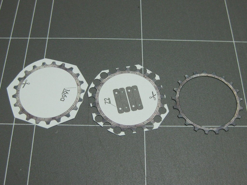
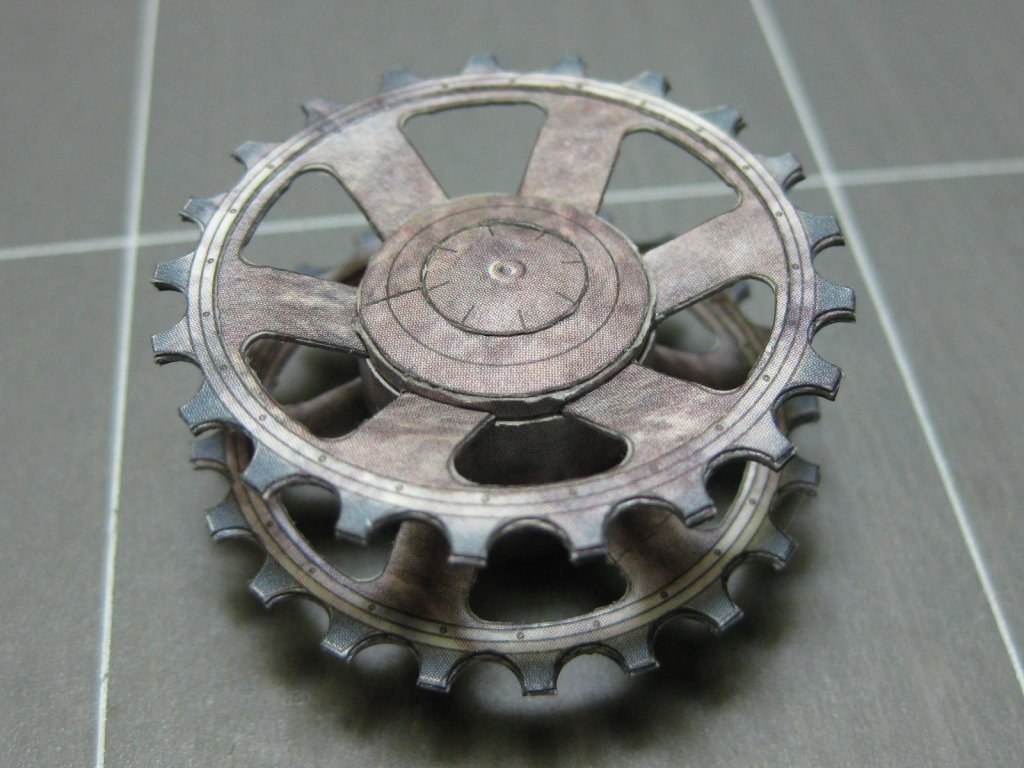
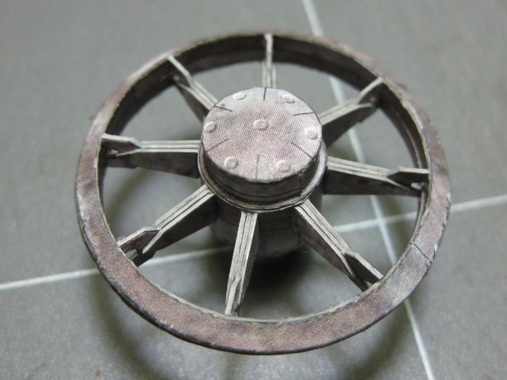
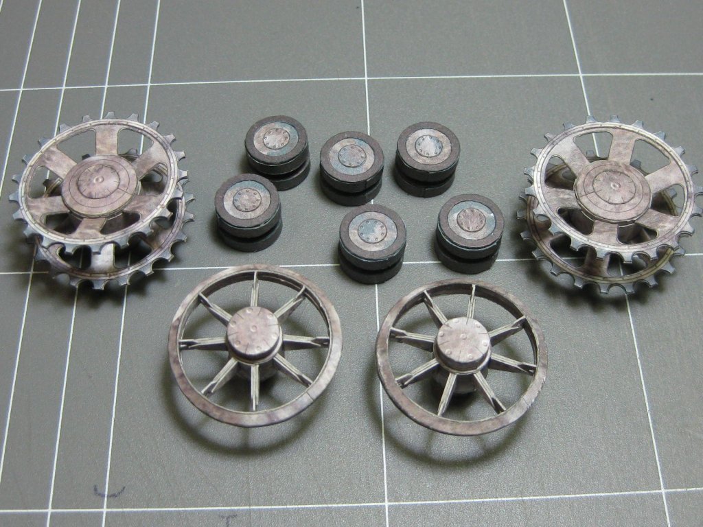
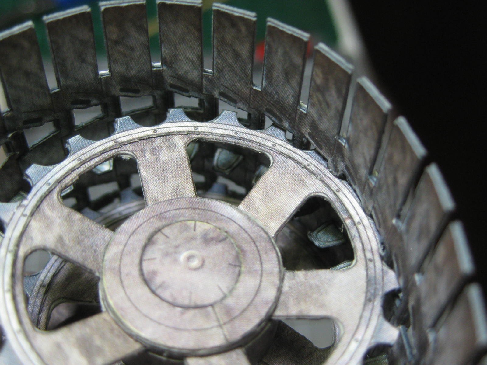
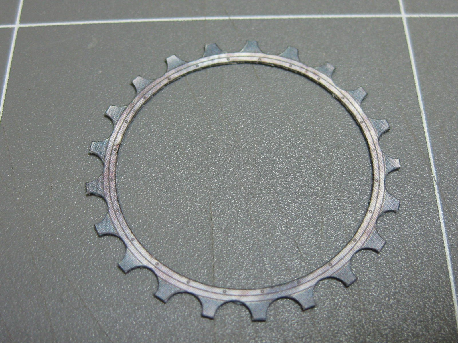
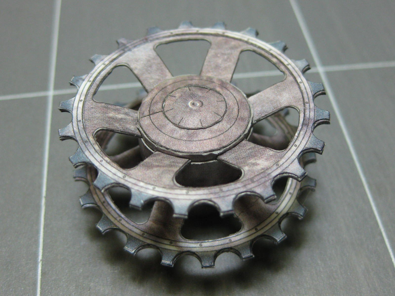
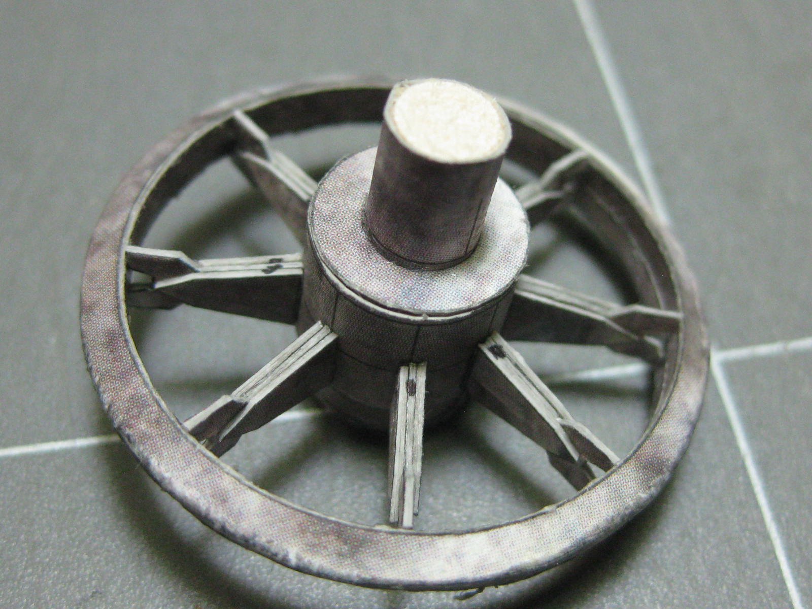
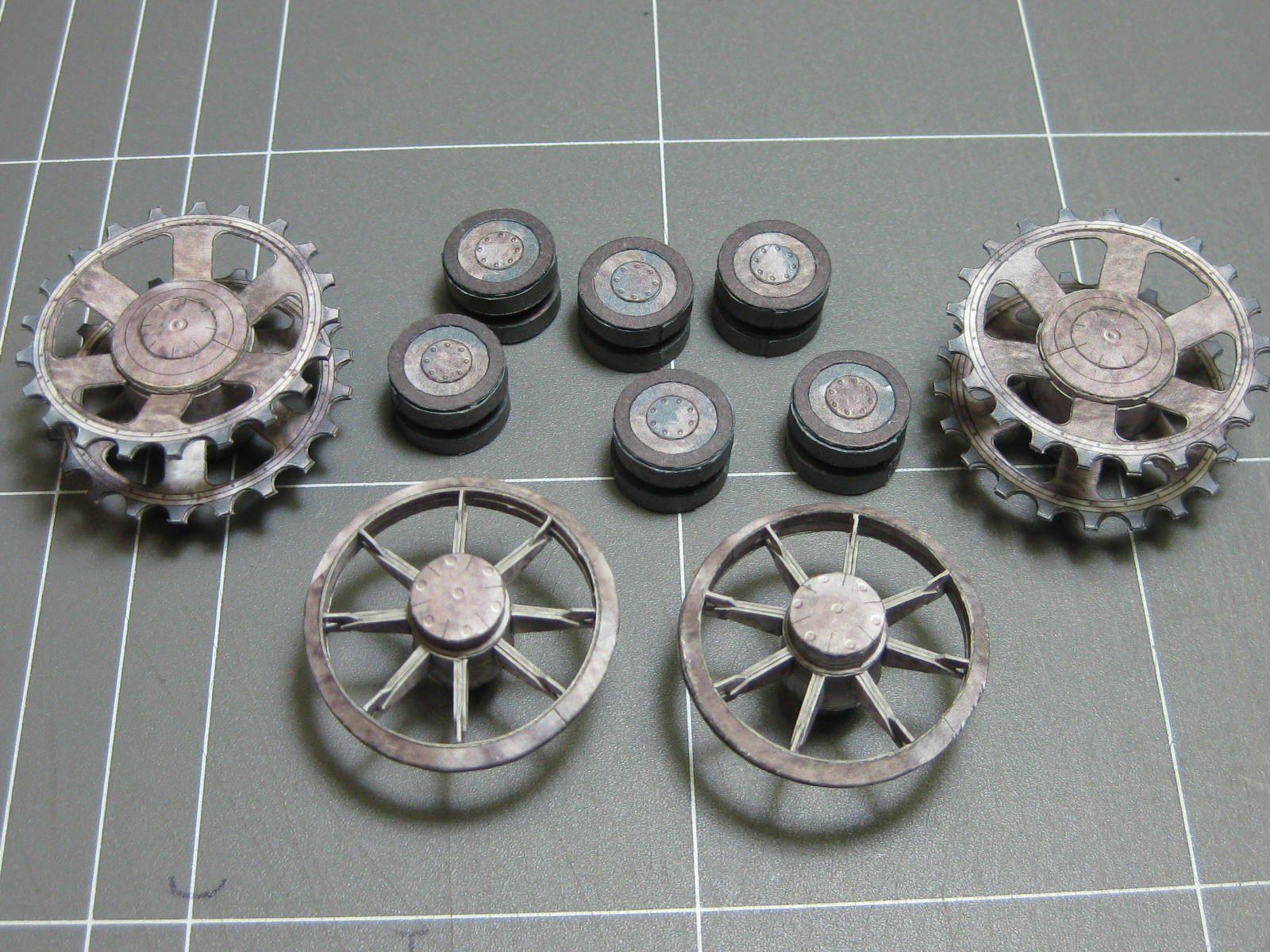
Five days later and I've made all the sprockets and rollers. To cut the teeth in the drive sprockets I used my punch set. There are 12 of these, a central one that contains the spokes and two outer ones to get the thickness correct :
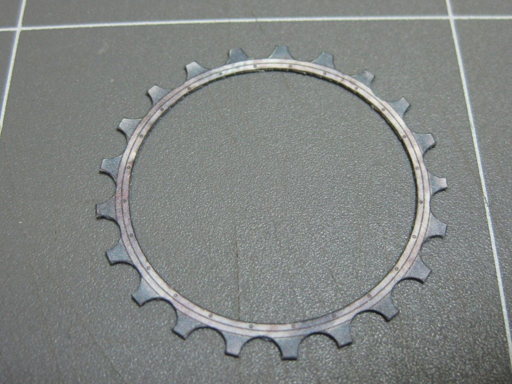

The idler sprockets :
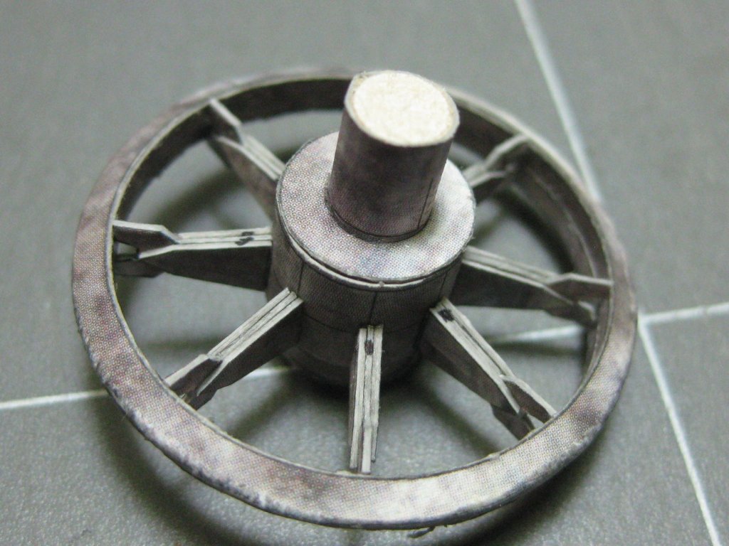
And the top rollers :
Danny
-
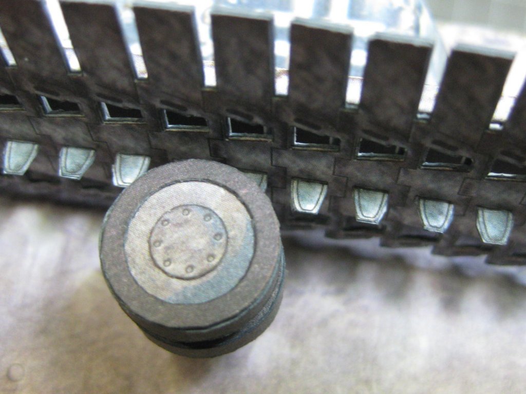
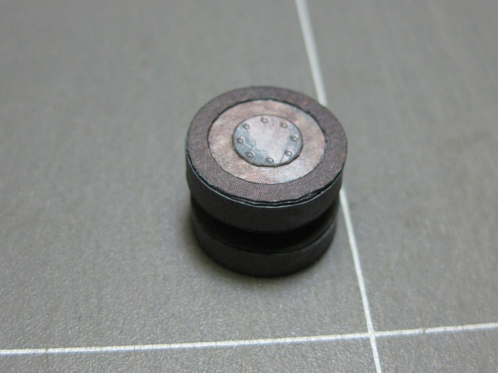
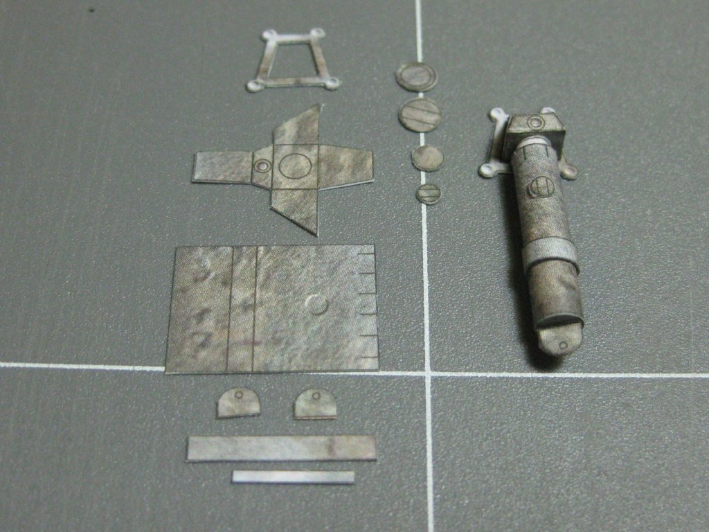
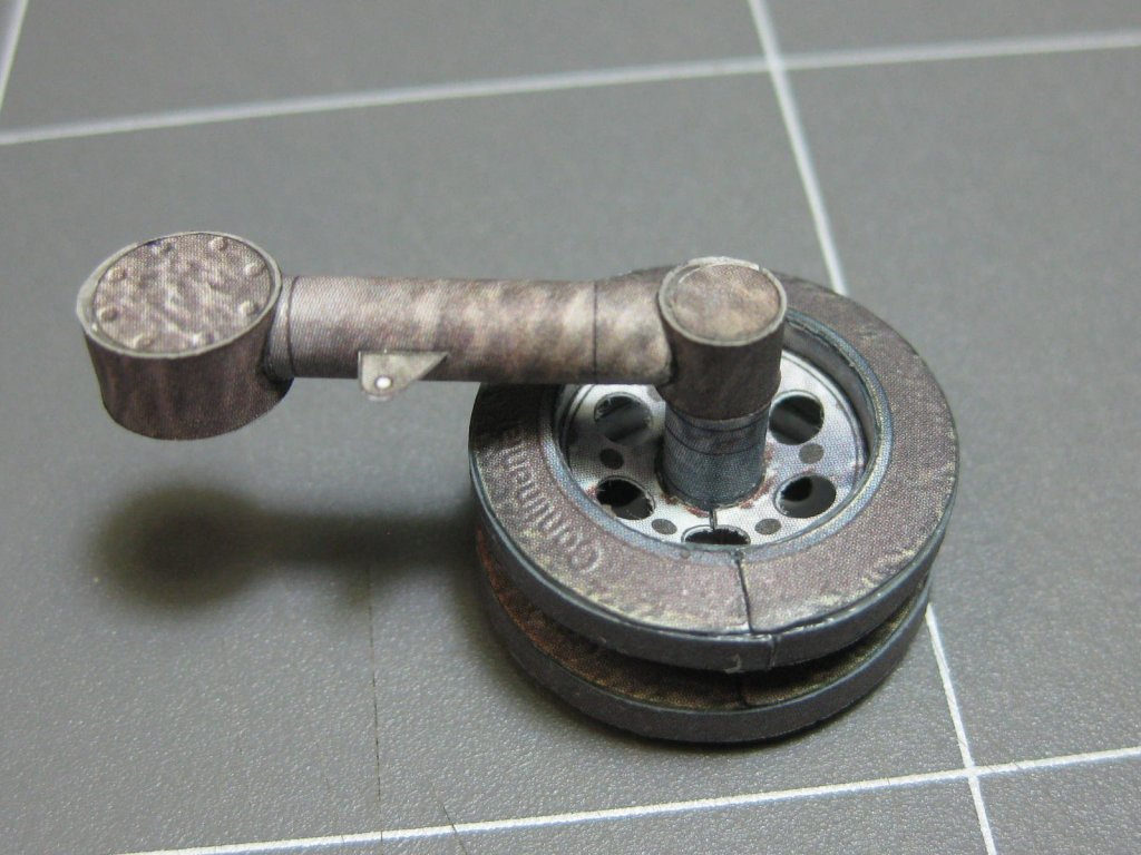
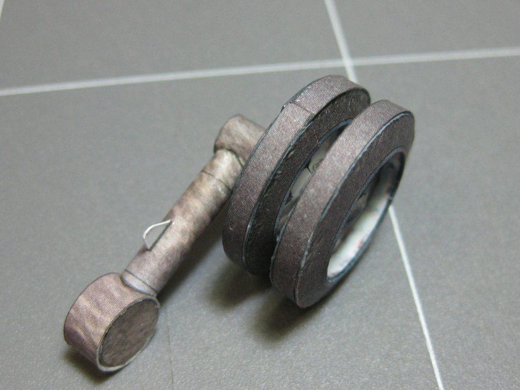
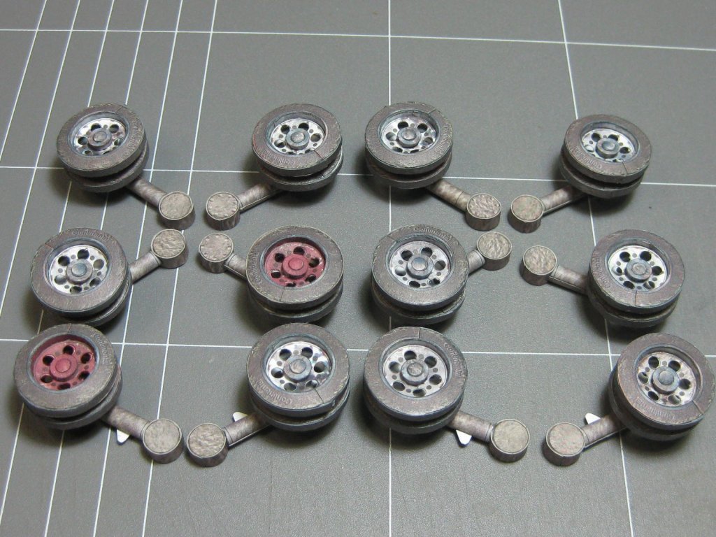
Continuing - the shock absorbers :
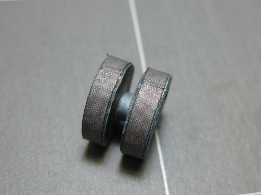
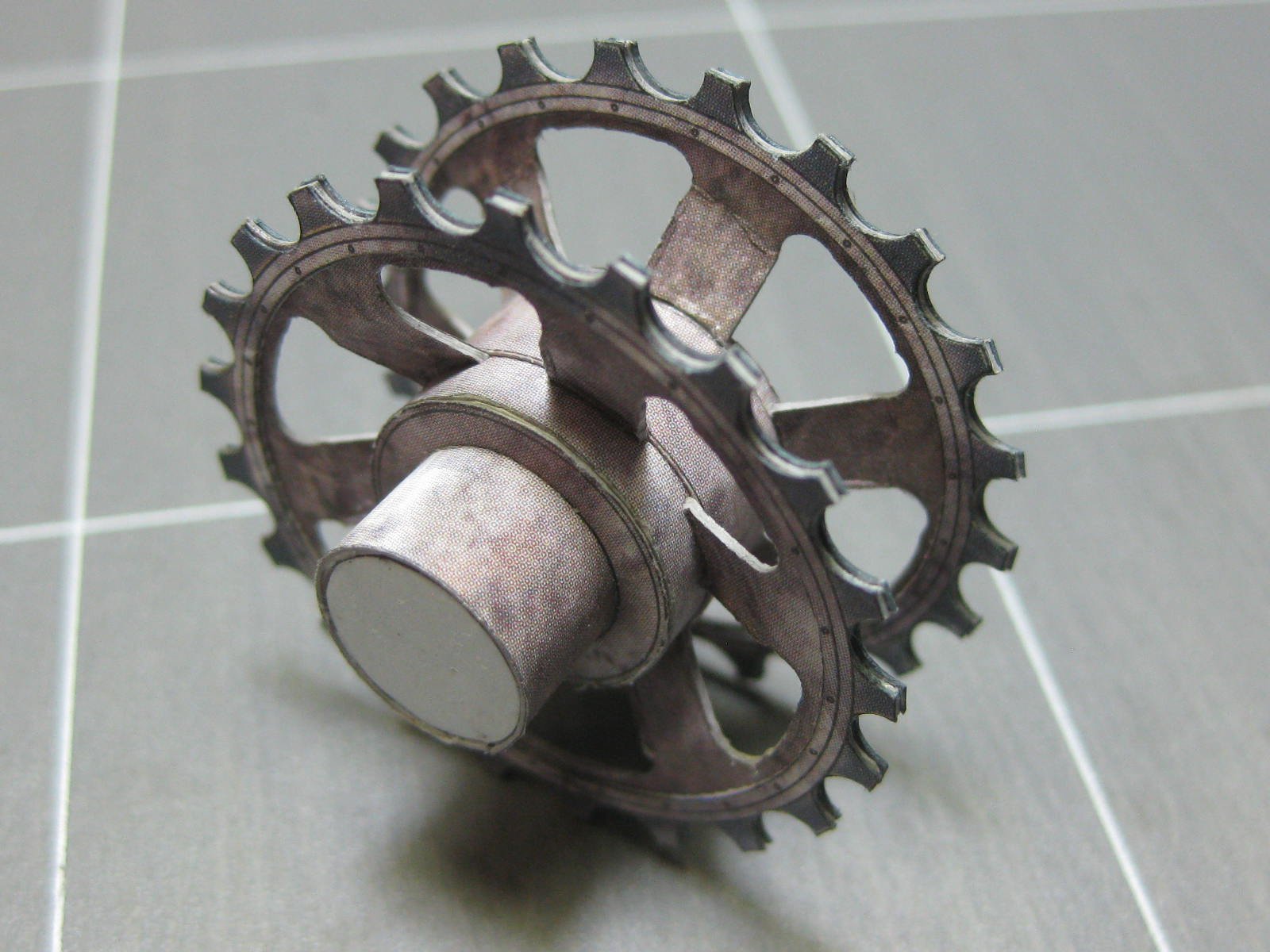
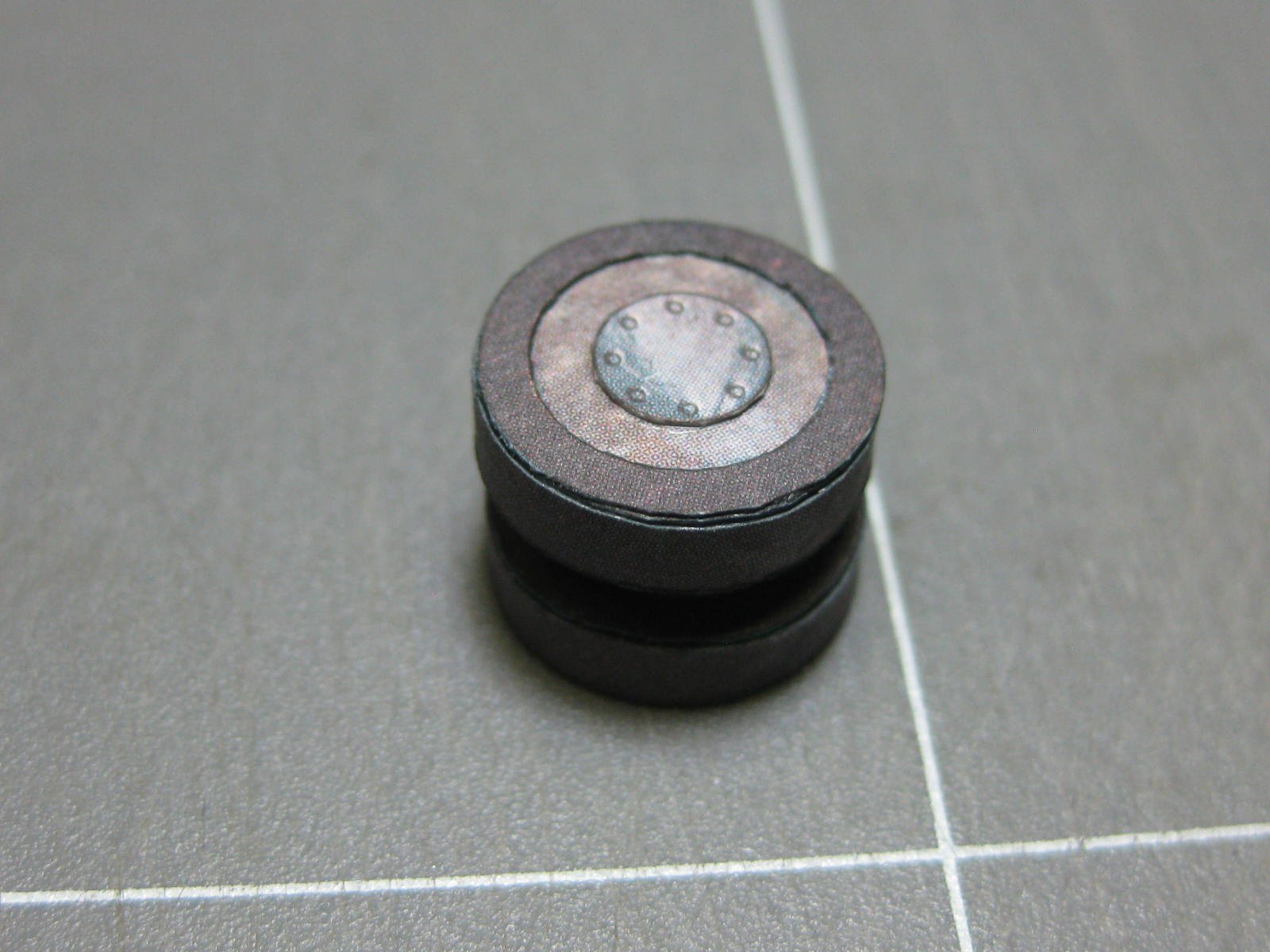
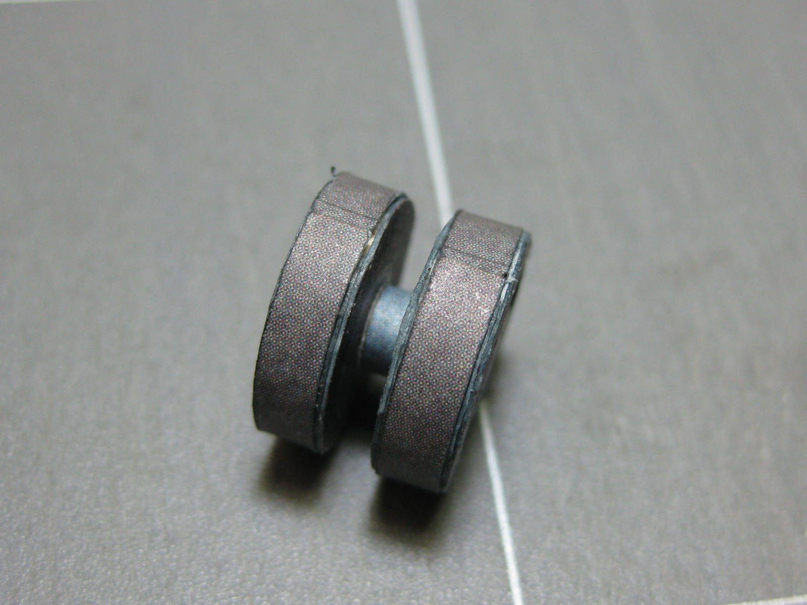
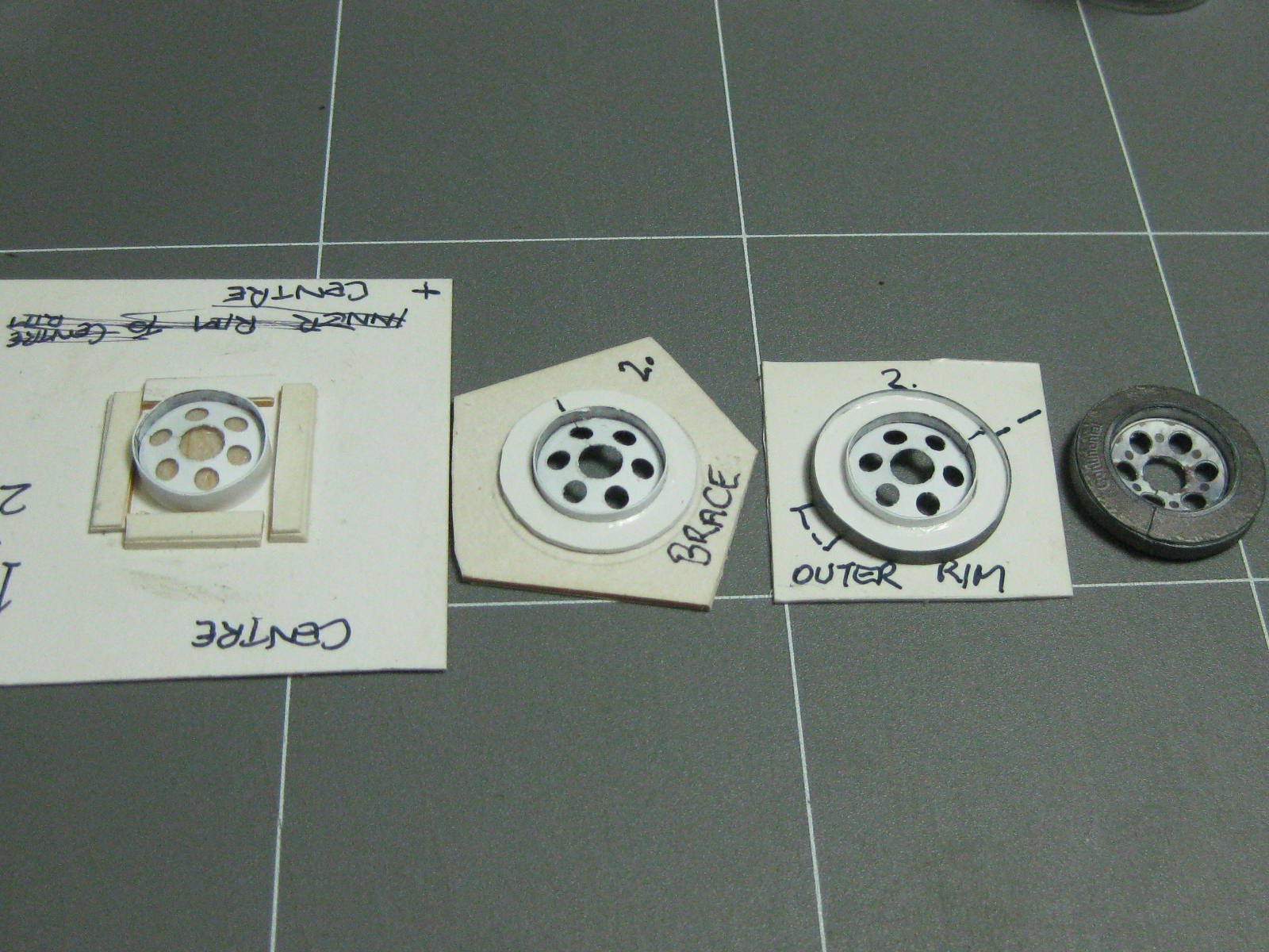
Next up is the reason I haven't updated lately - the 12 (plus 2 spares) bottom dual wheels. These have taken me 8 days to make, the equivalent of tying ratlines on a ship. I'm really glad to see the end of them at last
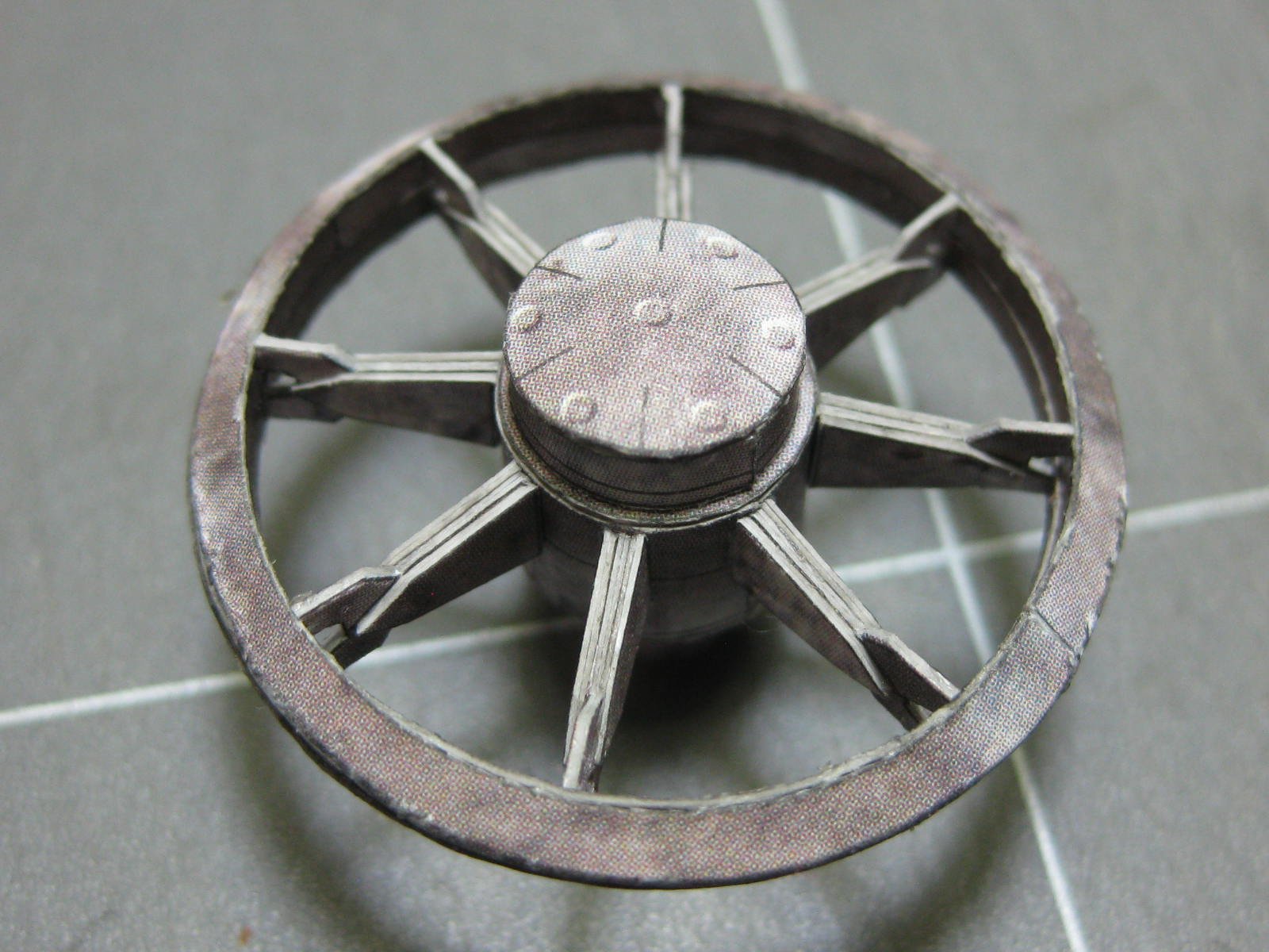
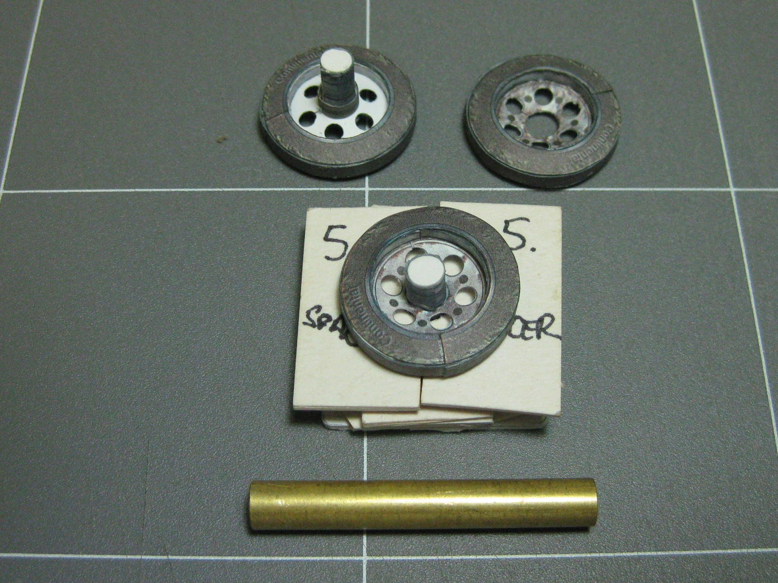
. Here are four of the wheels in the various jigs I made to assist assembly :
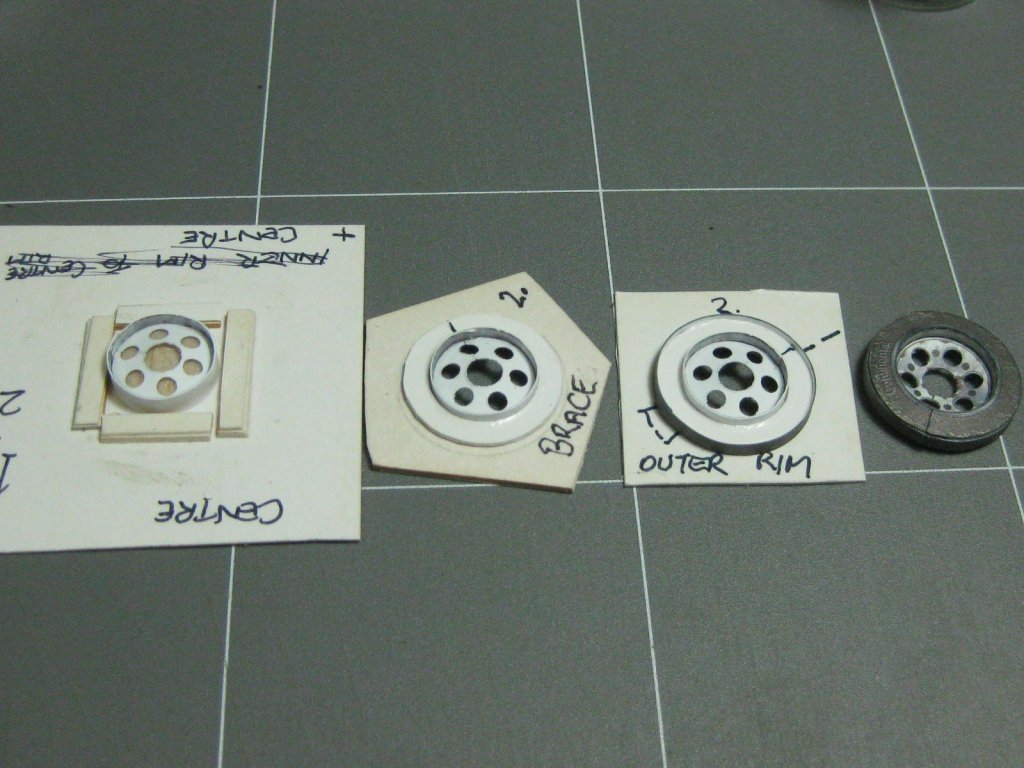
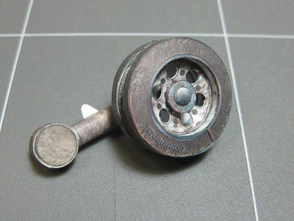
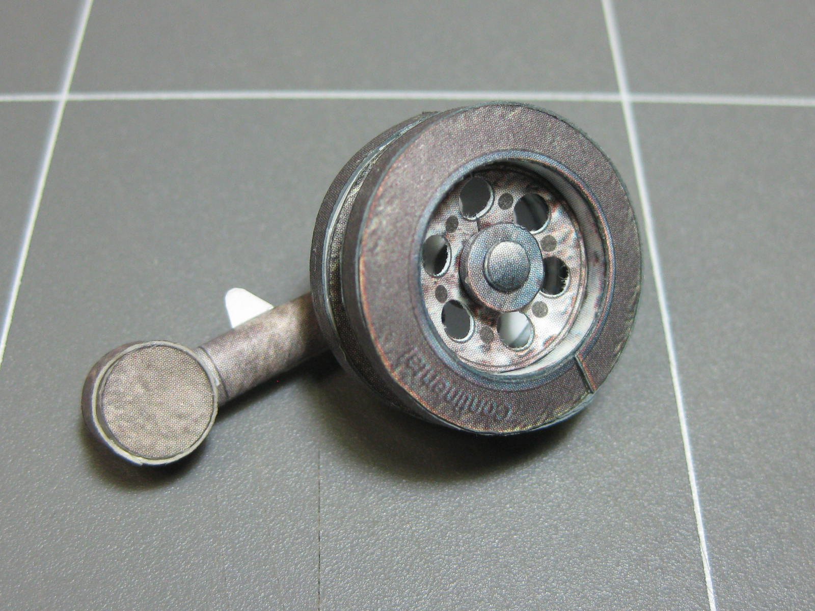
I used two spacers and a piece of brass tubing to fit the inner wheel to the axle :

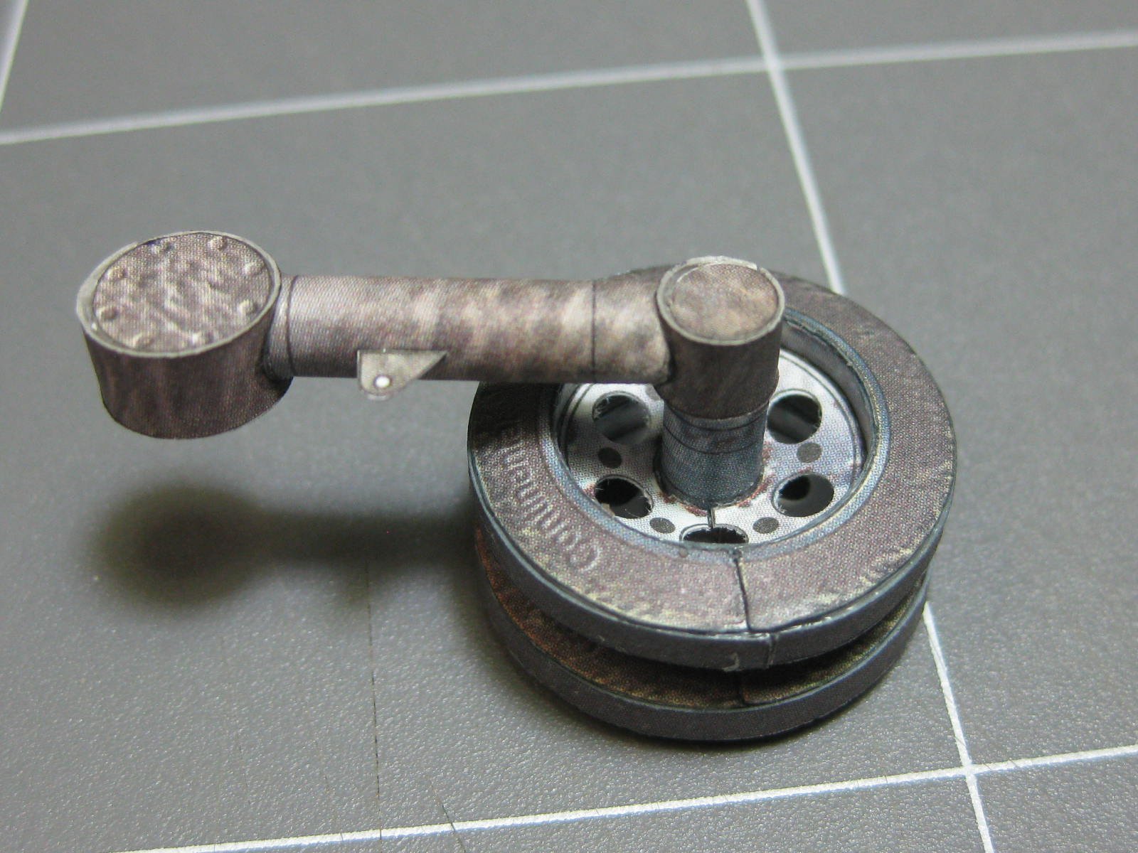
A finished wheel fitted to the suspension arm :
Danny
-
Pavol, I went one better and found THIS guy's build of the same kit. I've had to use the pics a few times to work out how to build some parts, and where they went
.
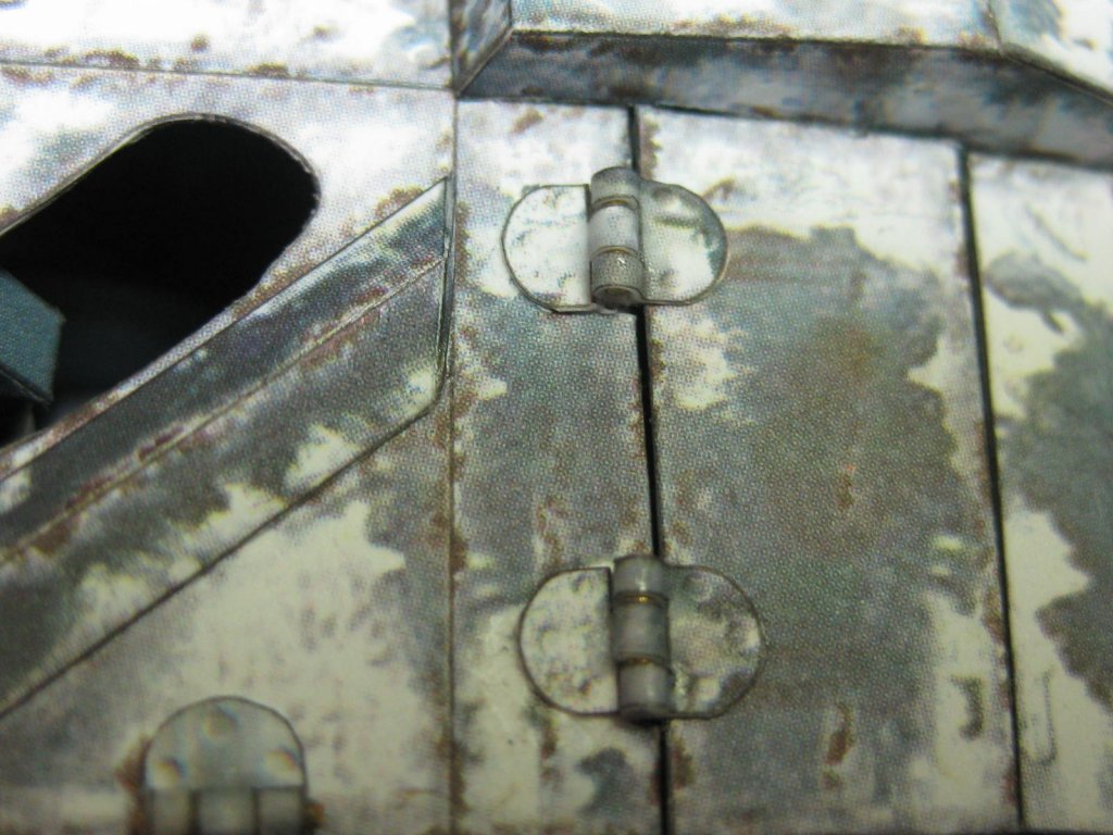
2 hours ago, maaaslo said:one thing about "working" latches and other parts...
you are asking for a trouble. although they look impressive to untrained eye, they are more often flimsy and weak. if you soak it in CA glue, might do the trick
I did that
. No discoloration is visible to the eye and they are VERY strong.
Thanks for the link to the tracks. I didn't find that one, but that's not unusual for GPM's site which is rather difficult to navigate sometimes
.
And thanks too for the site with that beautiful model - an inspiration indeed
.
Danny
- popeye the sailor, Canute and mtaylor
-
3
-
9 hours ago, hof00 said:
A thought that came to mind, for perhaps future Card Models of this complexity/detail, would be a "Cutaway?"
Having never created any model in Card, I would not know how feasible this would be.
Not casting aspersions on what you have created thus far, (Its awesome!!), just that the interior detail is largely lost once everything is put together.
Thoughts?
Thanks Mark and G'day Hof. I definitely had a cutaway in mind before starting the model, but the more I got into it the more I realized it would be virtually impossible with this particular one. I could have made nearly the whole top, from the front of the turret to the back of the engine cover, in one piece that lifts off but it would have created too many alignment and stability issues. I did the best compromise I could by making the hatches moveable.
Doing cutaways on card models wouldn't be any more difficult than in any other media, just not on this particular one. Anyhow, isn't actually BUILDING the model most of the fun? I don't look at them much after they are finished
.
Danny
- mtaylor, Canute, pontiachedmark and 2 others
-
5
-
2 hours ago, ubjs said:
Hi
The link to small craft points to plastic and resin models, I cant find a link to small craft.
Fixed. Thank you for pointing this out
.
Danny
-
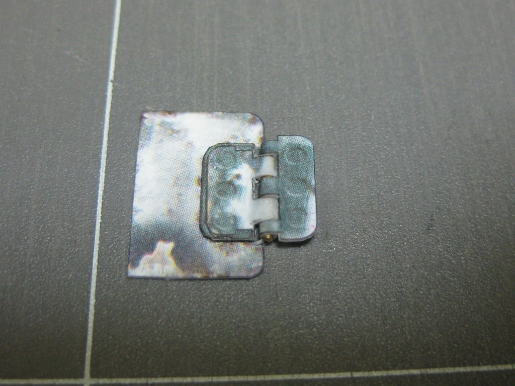
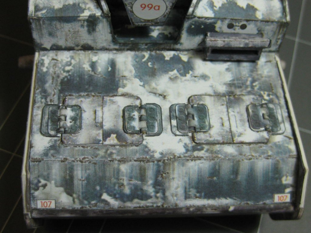
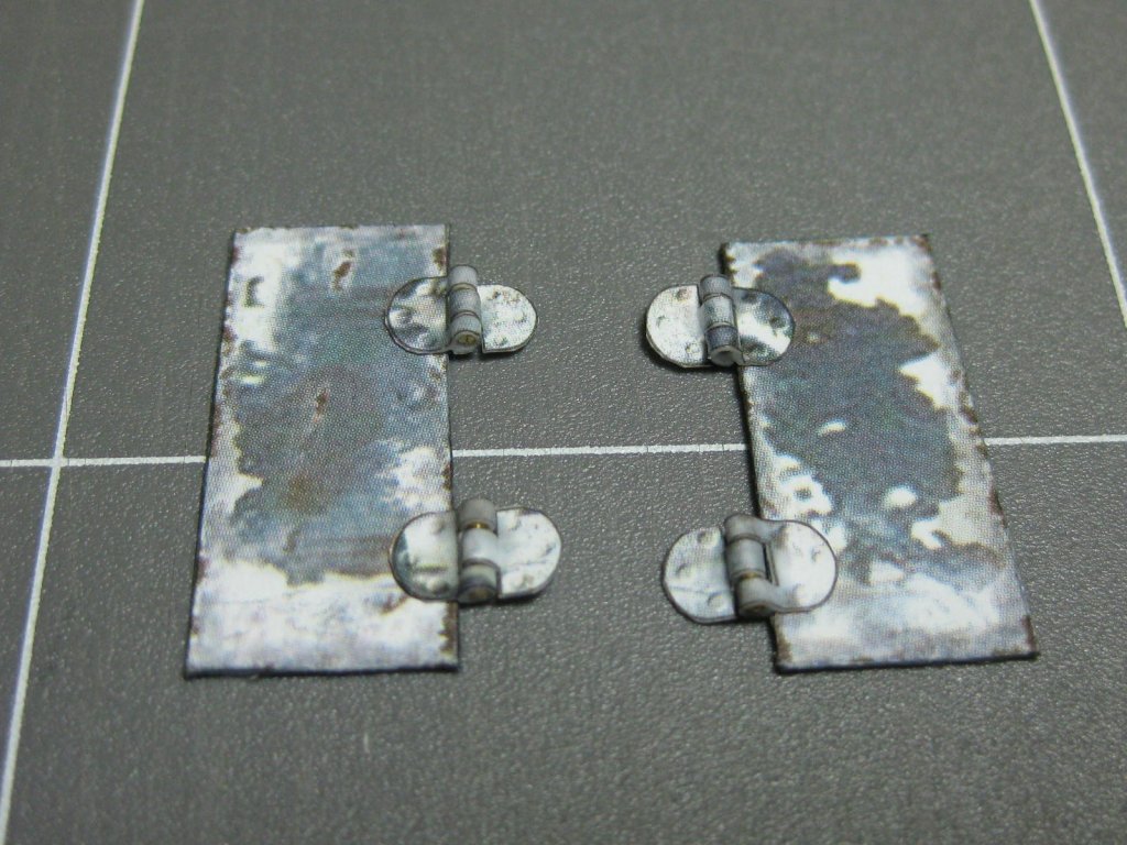
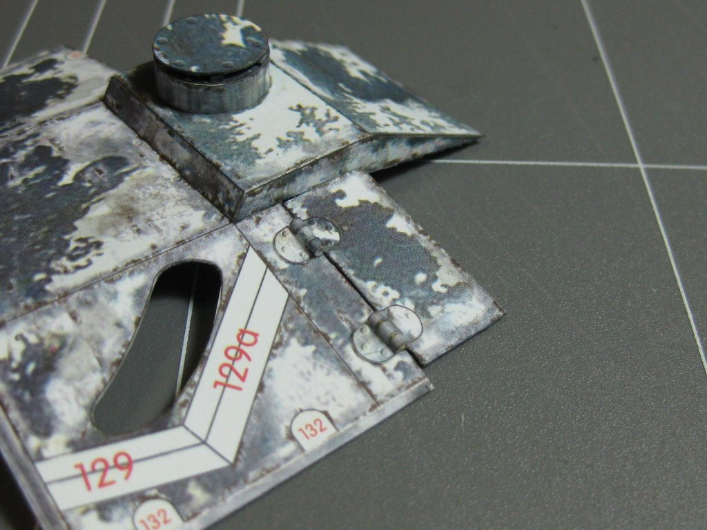
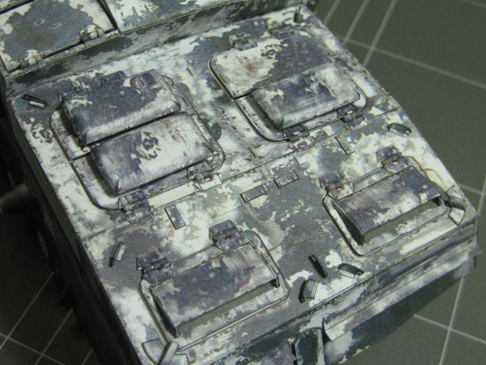
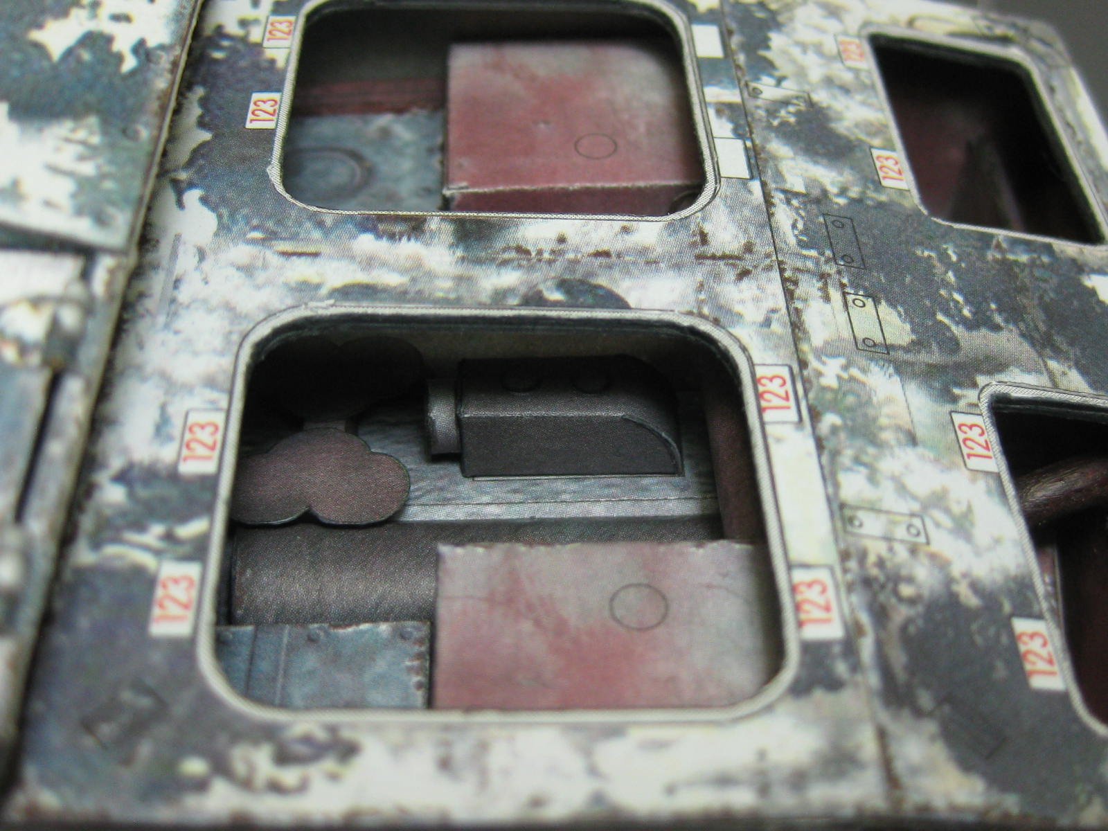
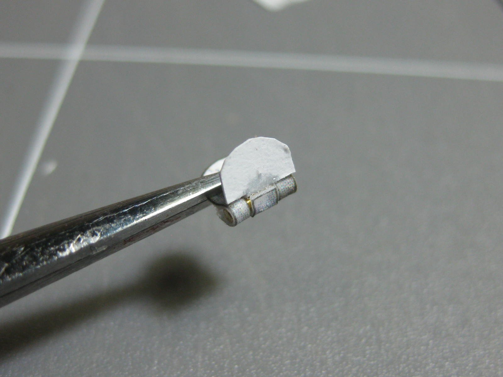
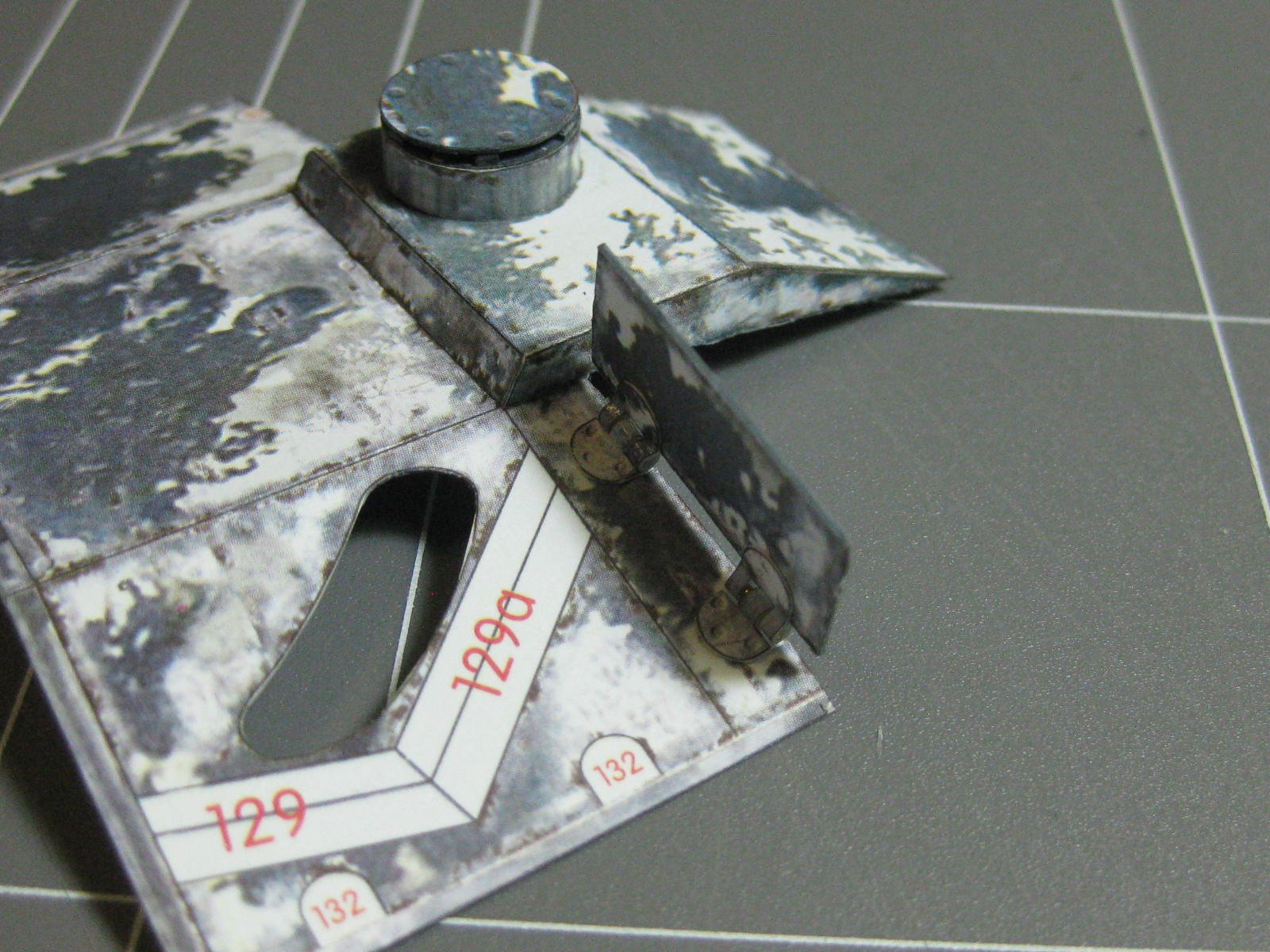
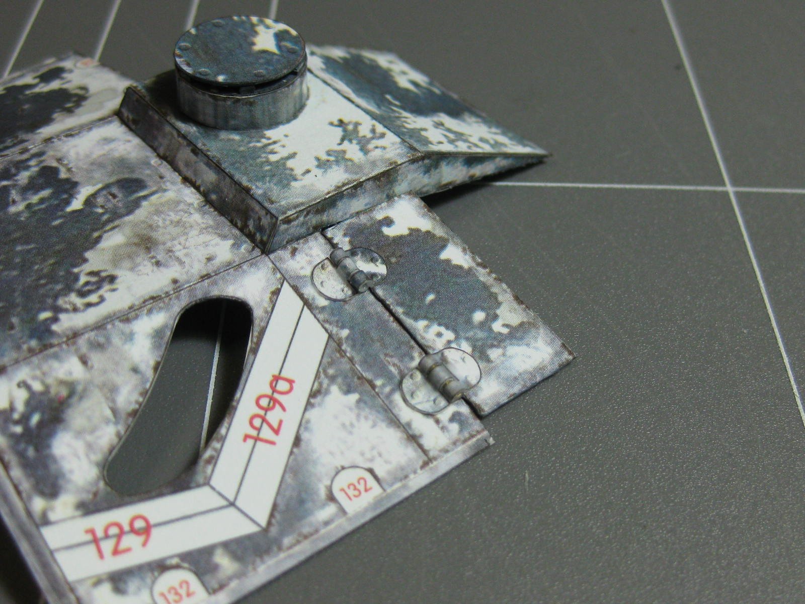
The front hatches only have one hinge each, so it's larger than the others with 2 and 3 sections. This of course makes it a bit harder to construct :

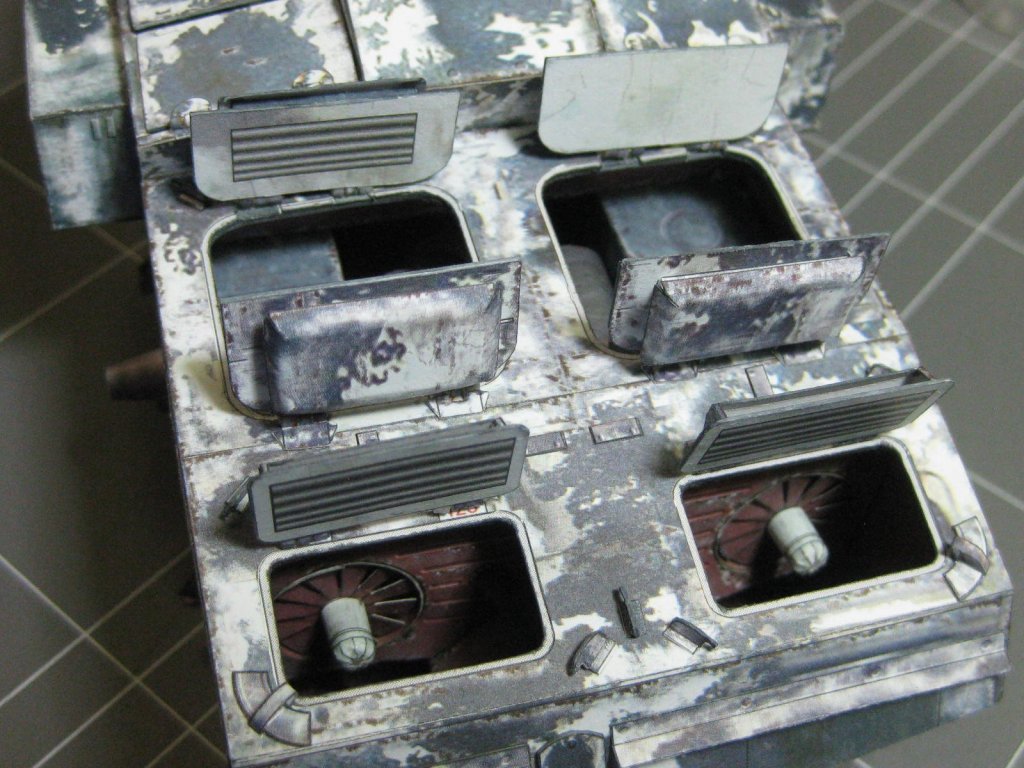
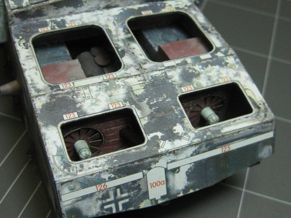
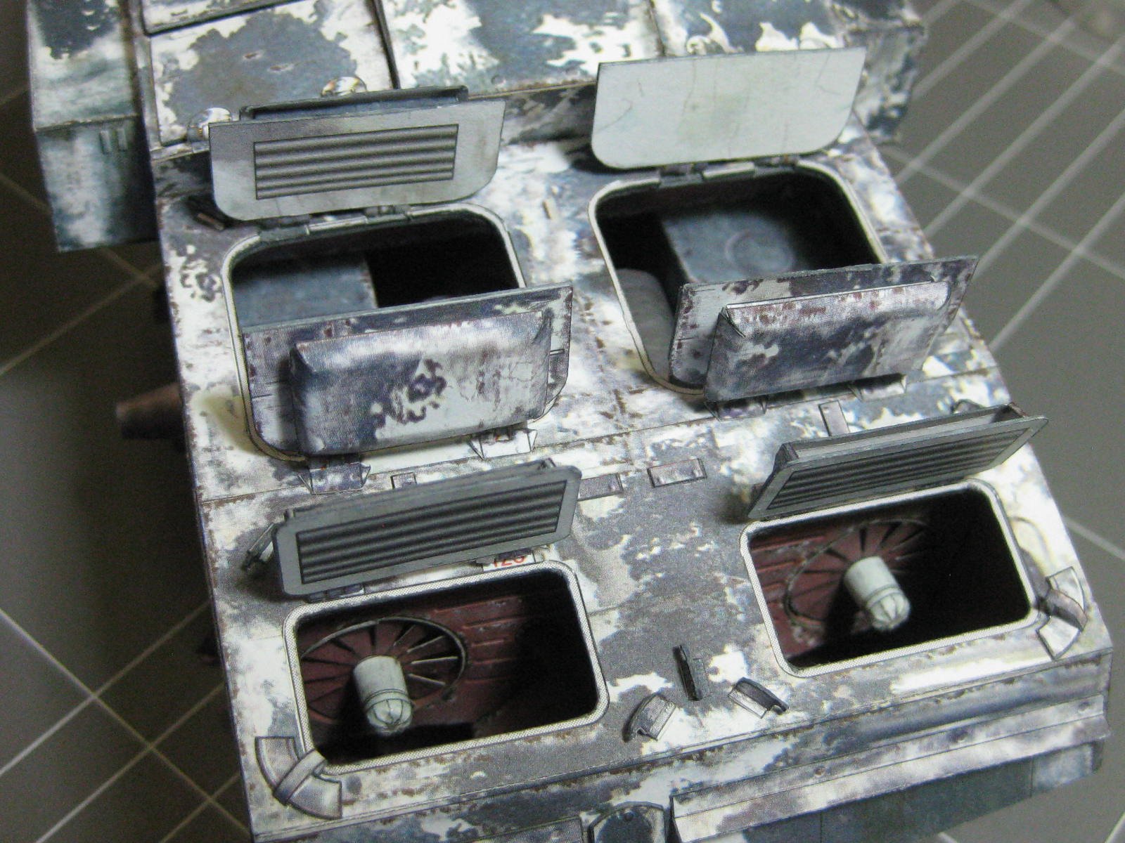
The engine cover hatches are a more complex arrangement, with ventilation for engine cooling :

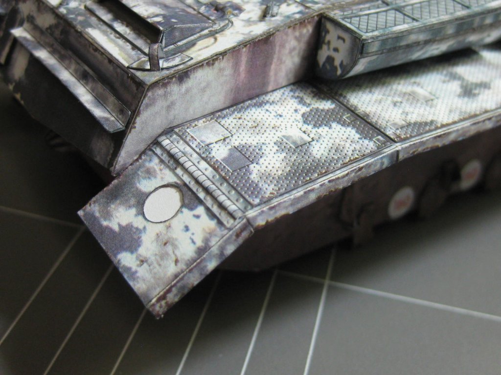
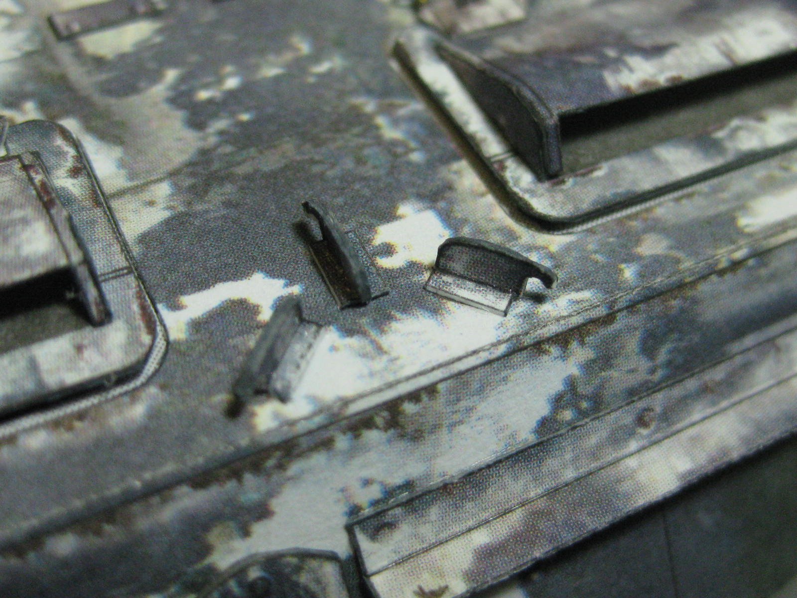
There are also some small details, like these "fairleads" (for want of a better word) that support the tow cable :

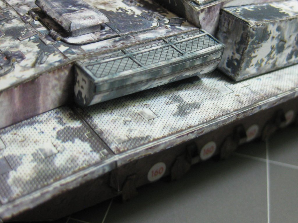
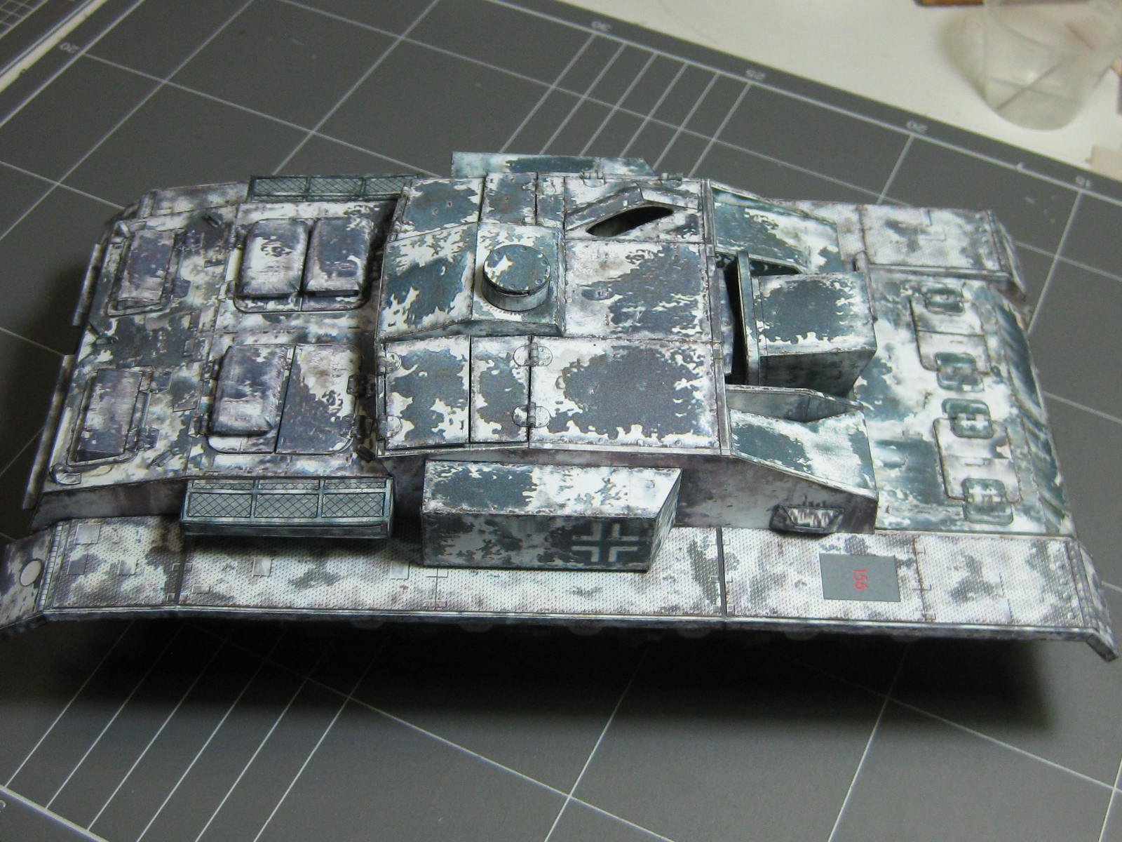
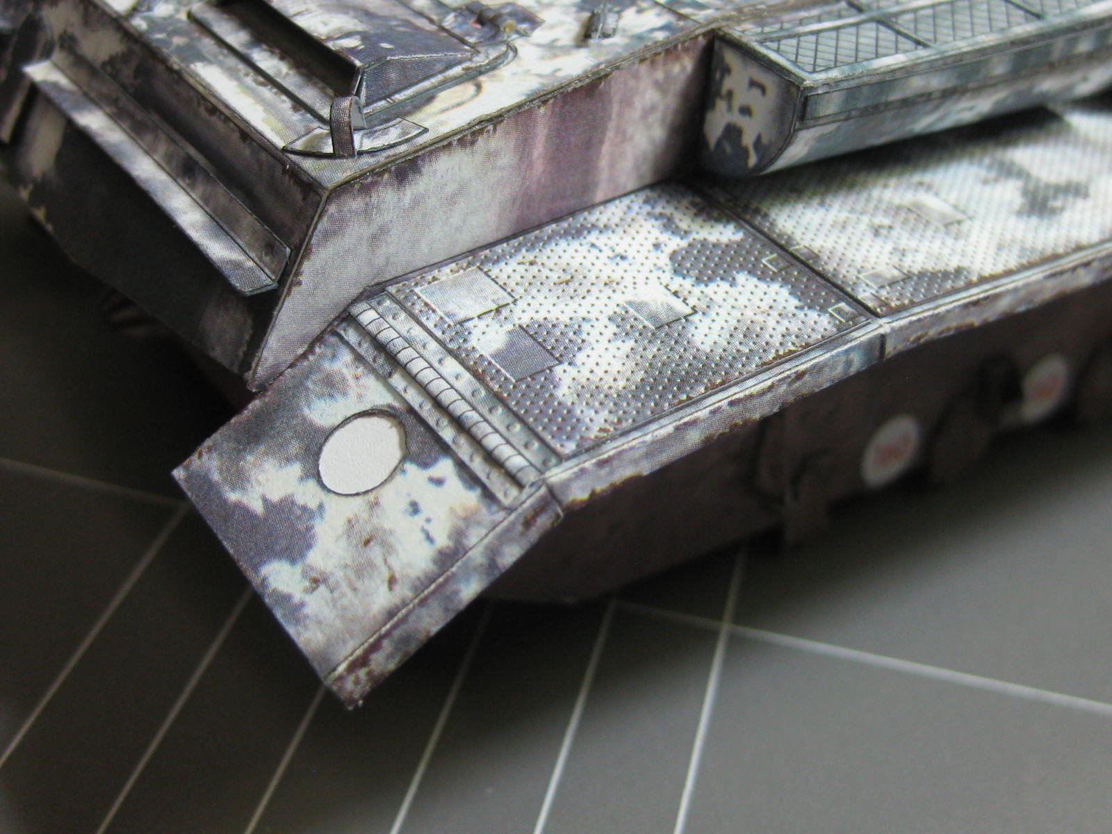
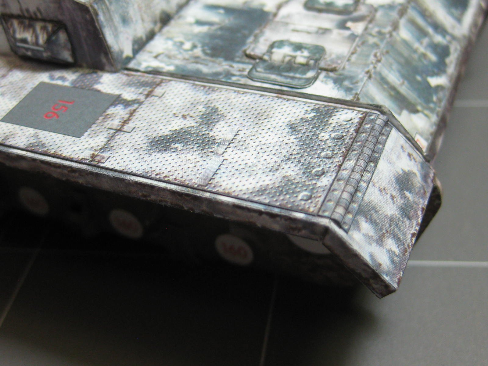
With all the hatches finished it's time to fit the track guards :

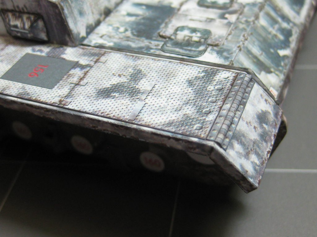
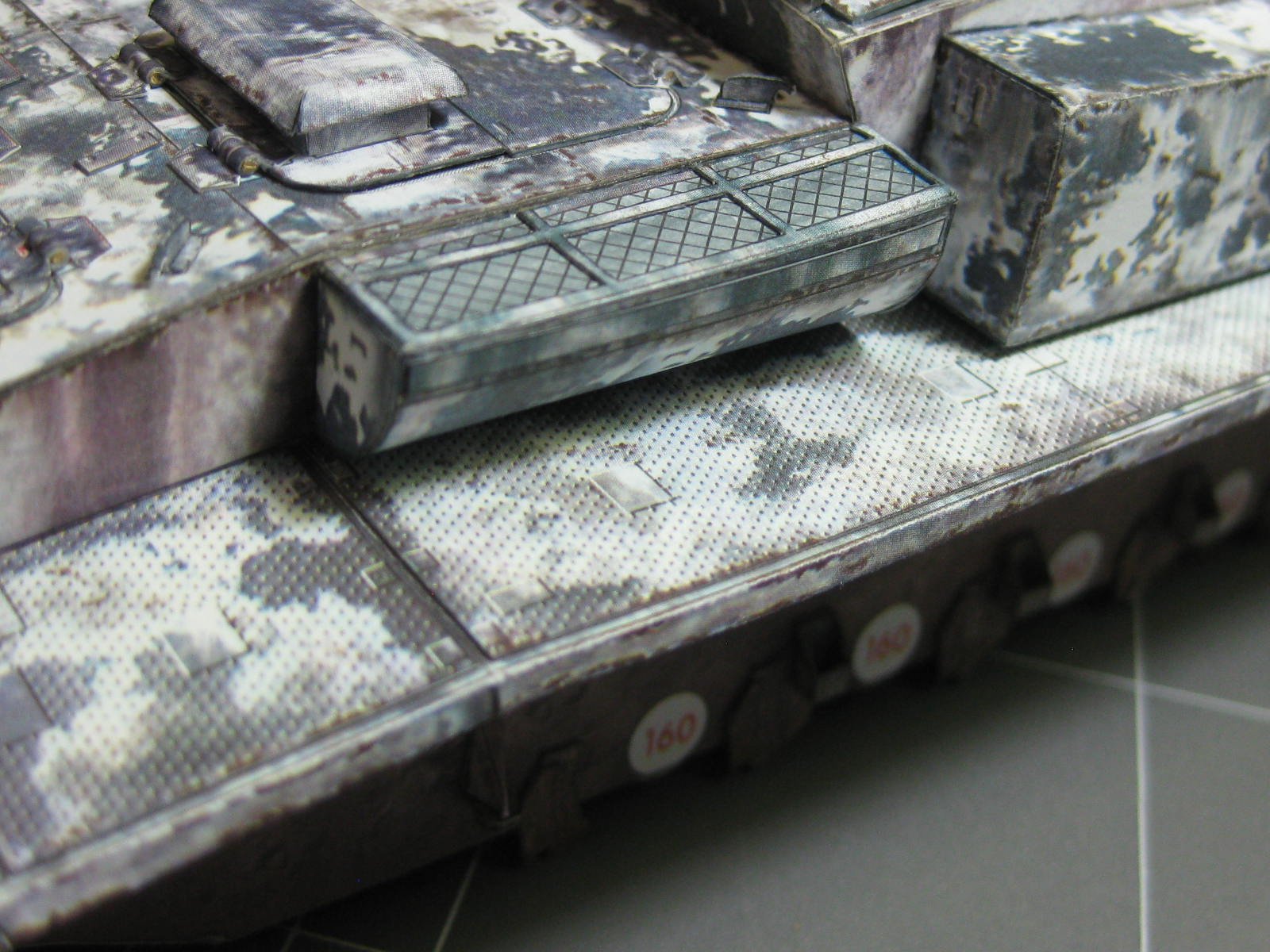
Also the air filters :
Danny
-
Thanks for the info Patrick.
7 hours ago, hof00 said:I'm looking forward to how you are going to tackle the Tracks. Articulated?
I'm not sure about that yet. The kit gives you three options, one of them being articulated tracks (that explains the 5 pages of tracks
). I'll certainly give it a try.
Danny
- Baker, popeye the sailor, cog and 2 others
-
5
-
On 12/5/2018 at 10:21 AM, cog said:
do you have a video???
No.
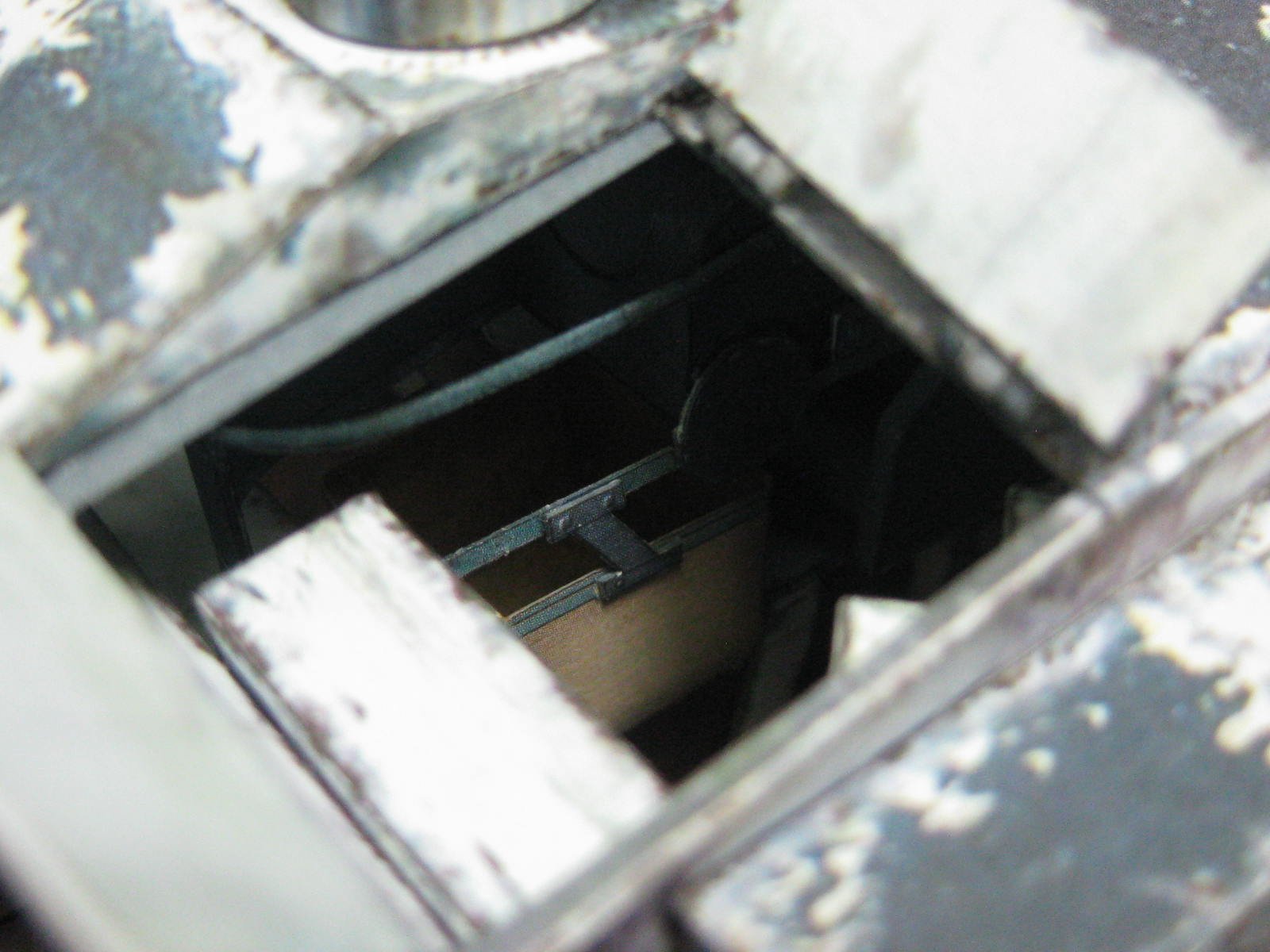
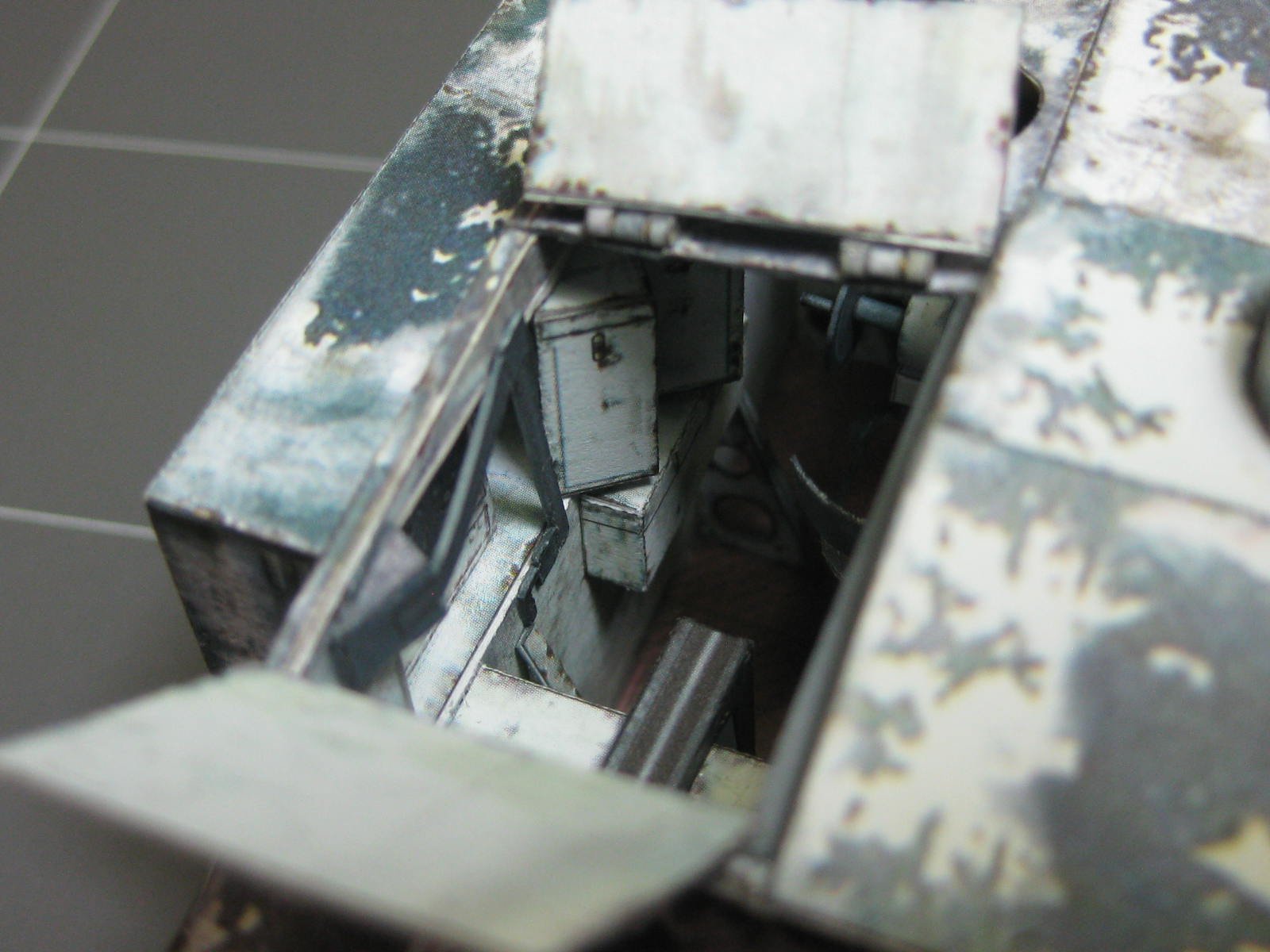
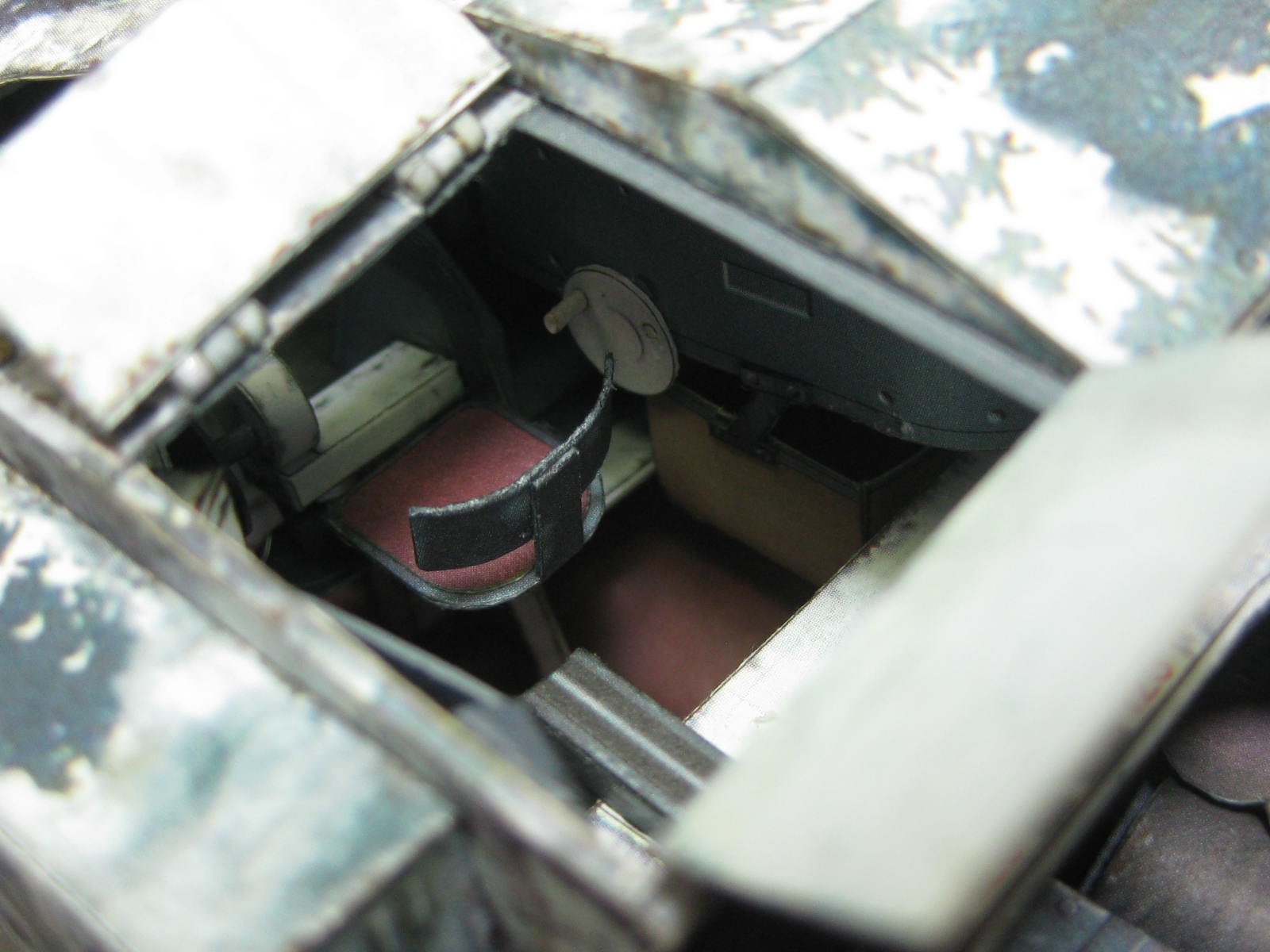
On 12/5/2018 at 9:51 PM, Richmond said:Those armour models are so illogical. They require you to create the detail and then ask you to lock it away from sight.
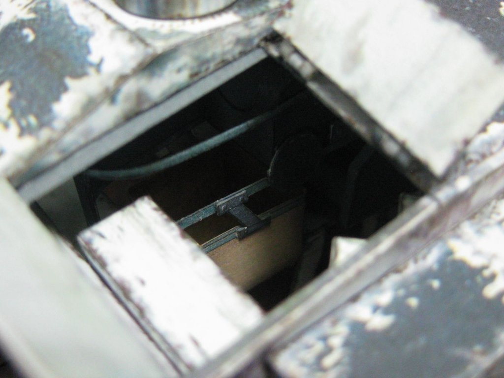
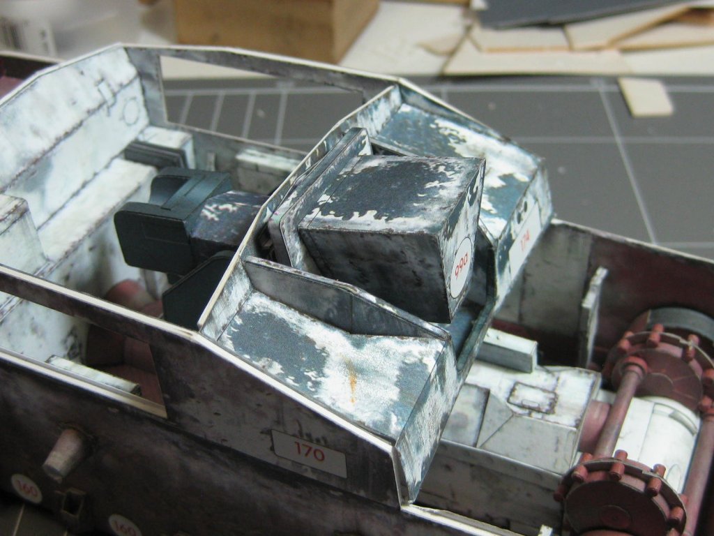
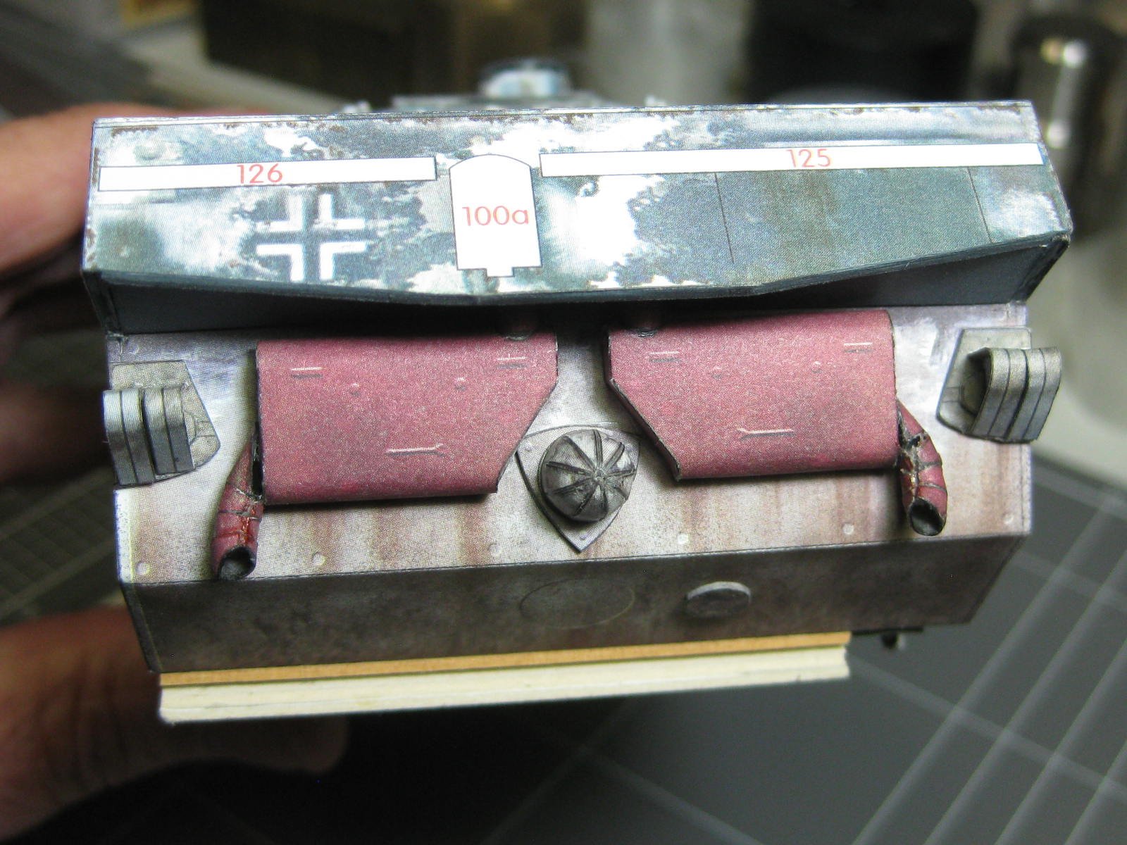
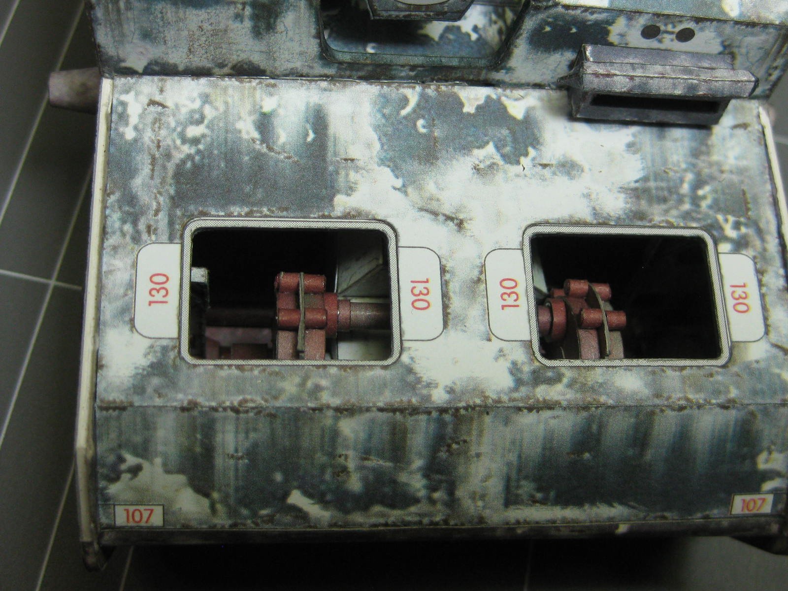
As you will see from the next lot of pics. I've now glued on all the upper panels, and most interior detail has vanished. Here are the bits you CAN still see (just as well I took lots of pics earlier
) :

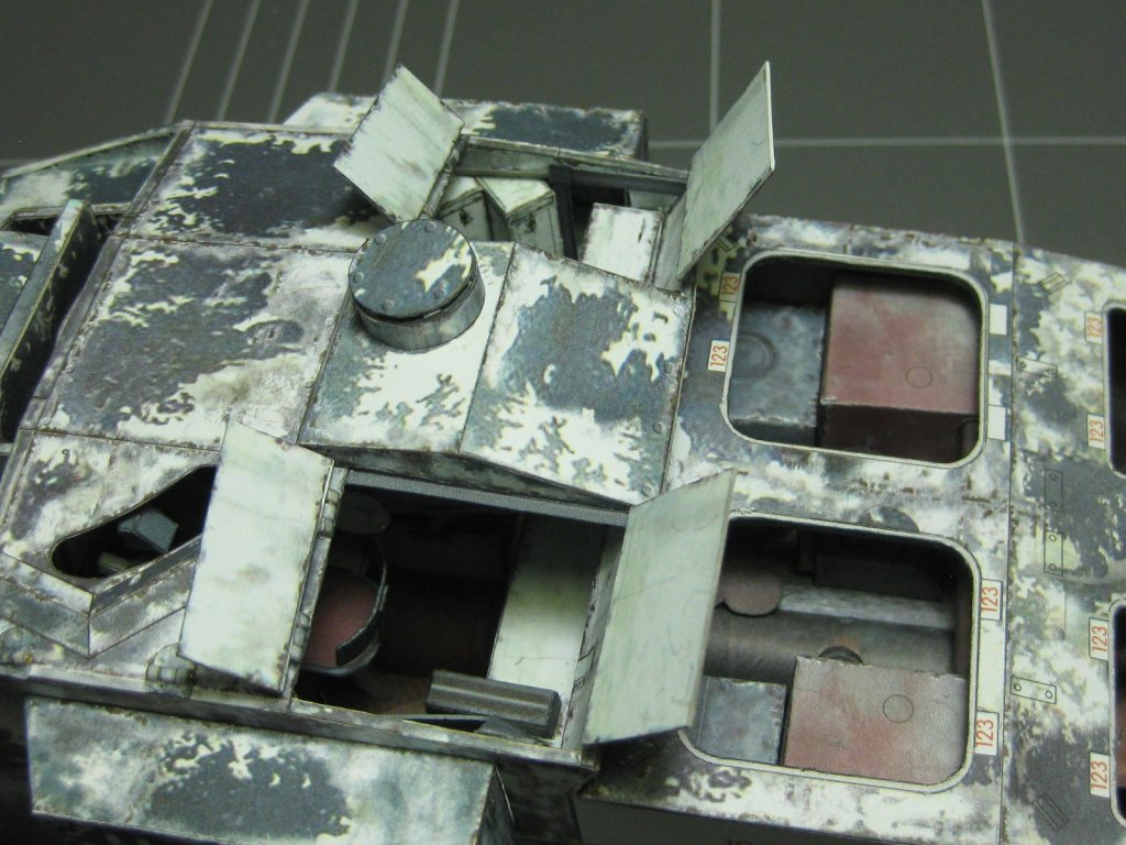


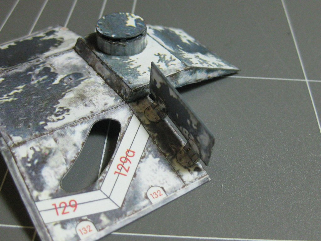
 On 12/5/2018 at 9:51 PM, Richmond said:
Look forward to seeing your hinge solution.
And just for you Richmond :
Danny
-
4 hours ago, David1962 said:
Looks like a labour of love Danny! this is amazing! never seen so much detailed work!
Thanks David. I consider my HMS Hood to be better
.
Danny
- popeye the sailor, Canute and mtaylor
-
3
-
On 12/6/2018 at 7:26 AM, David1962 said:
Hi Danny 1mm super thick card 480gsm??
I don't know how many gsm the 1mm card is David, but I suspect it's heavier again. You can buy the card from GPM, they also have the 0.5mm, but postage isn't cheap so if you want to get some from them then take a look at their site and see if there's anything else you want and add it to the order. It won't cost much extra (unless you buy a LOT of stuff
).
Danny
- Canute, popeye the sailor and mtaylor
-
3
-
On 12/6/2018 at 7:21 AM, David1962 said:
I had a look at it today and the deck colours look matched ok
I couldn't really spot the difference in the two sheets of decks until I'd cut them out and fitted them together. Hopefully mine was just a bad sheet of printing and yours is OK.
There are more laser-cut parts available than just the framing etc. They also supply all the smaller guns, radomes and a few other things as options which you have to buy separately. Also the photo-etch for the AA guns and other small parts (same deal). Check the first post or two for all the extras I bought.
Danny
- popeye the sailor, mtaylor and Canute
-
3
-
1 hour ago, David1962 said:
do I see thin plywood there on the hull? if not and it's card what thickness are you using please? got my GPM Bismarck today.
No plywood, that's the colour of the 1mm card. There is also laser-cut 0.5mm card in the kit for things like the decks and superstructure.
Hope you have fun with your Bismarck. I also hope they fixed the issue I had with the mis-matched colours of the main decks.
If you didn't get the laser-cut options I would STRONGLY recommend that you put the model on hold and order them.
Danny
- popeye the sailor, mtaylor, ccoyle and 1 other
-
4
-
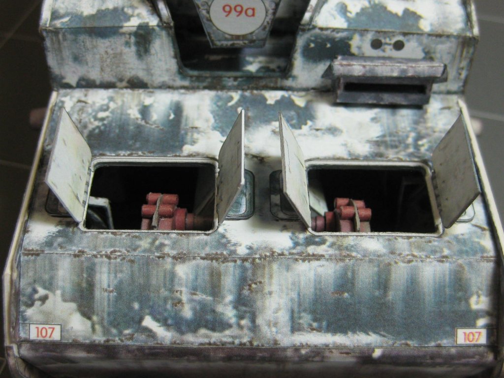
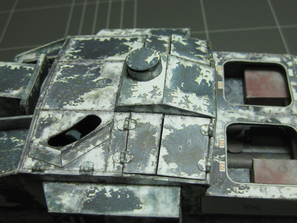
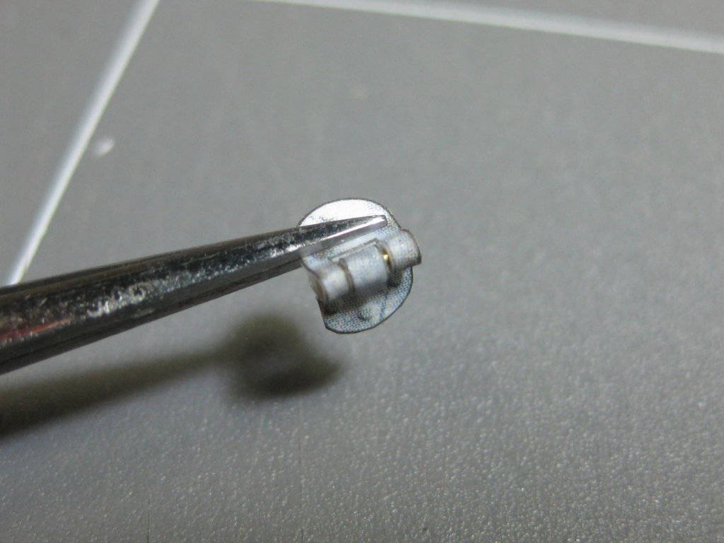
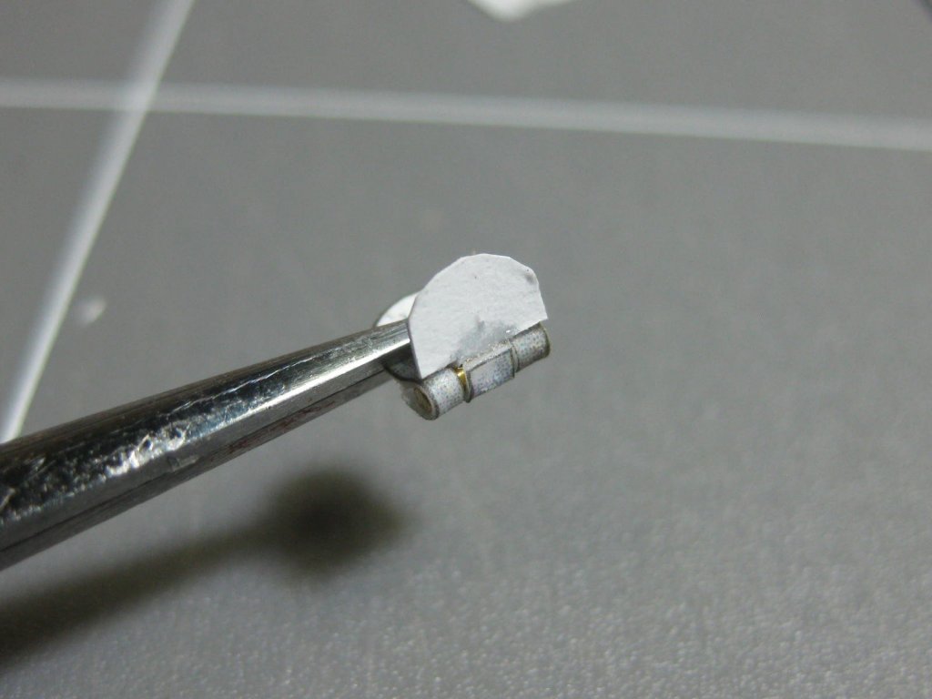
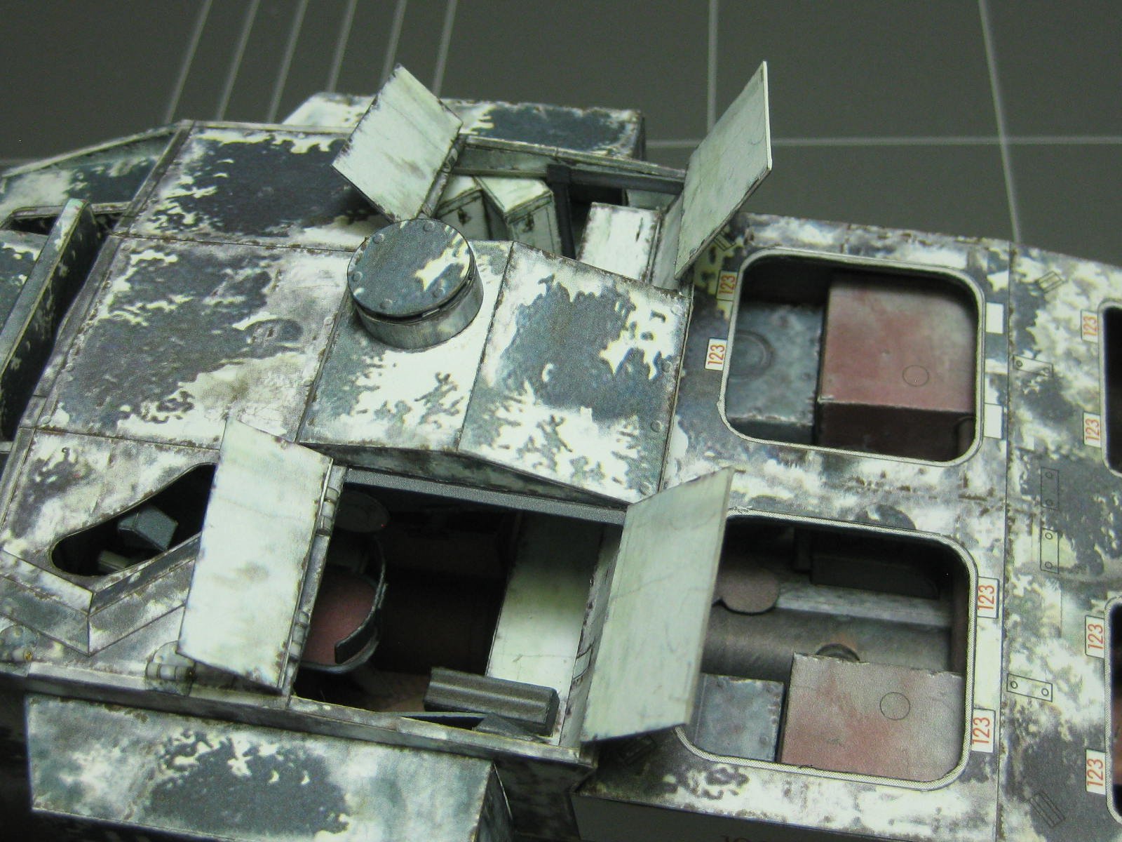
I had planned to make the roof removable to show off the interior, but it turns out I can't. So I decided to make the four hatches with working hinges so some of the interior will be visible. Here are the first two - they work perfectly
:
Danny
- popeye the sailor, herask, ccoyle and 10 others
-
13
-
21 hours ago, nikbud said:
Looking good!
Is that arrangement going to be stiff enough so that the gun won't "droop"?
Maybe. I'll have to actually install the barrel and then make some modifications to the elevation pivot if needed.
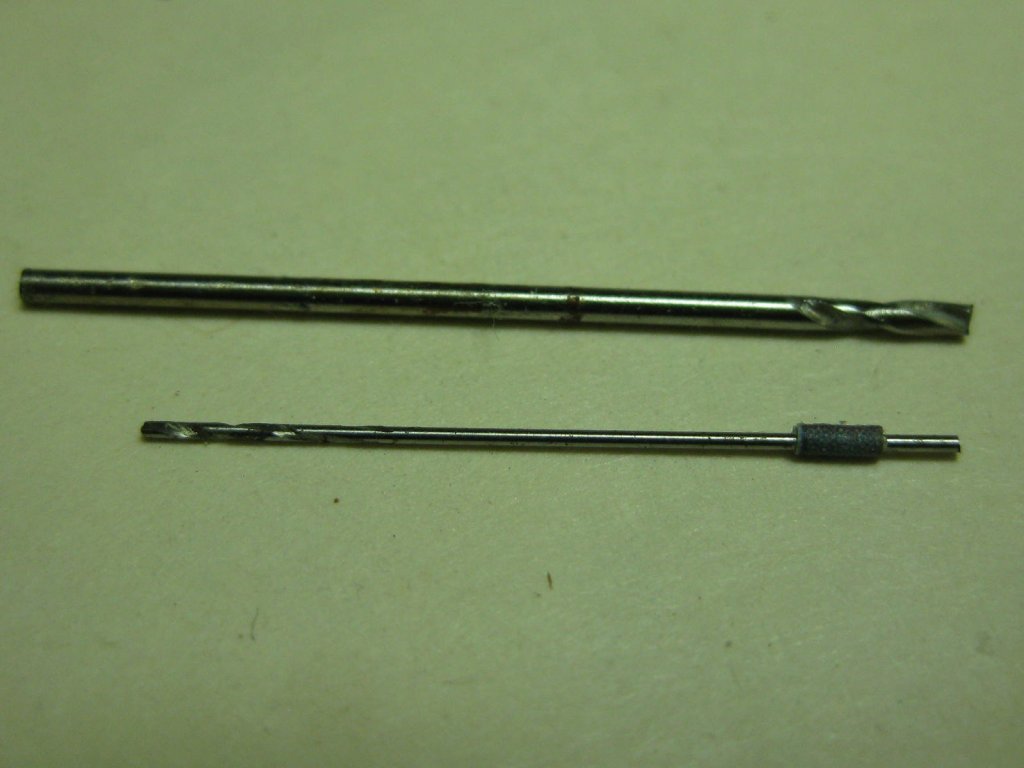
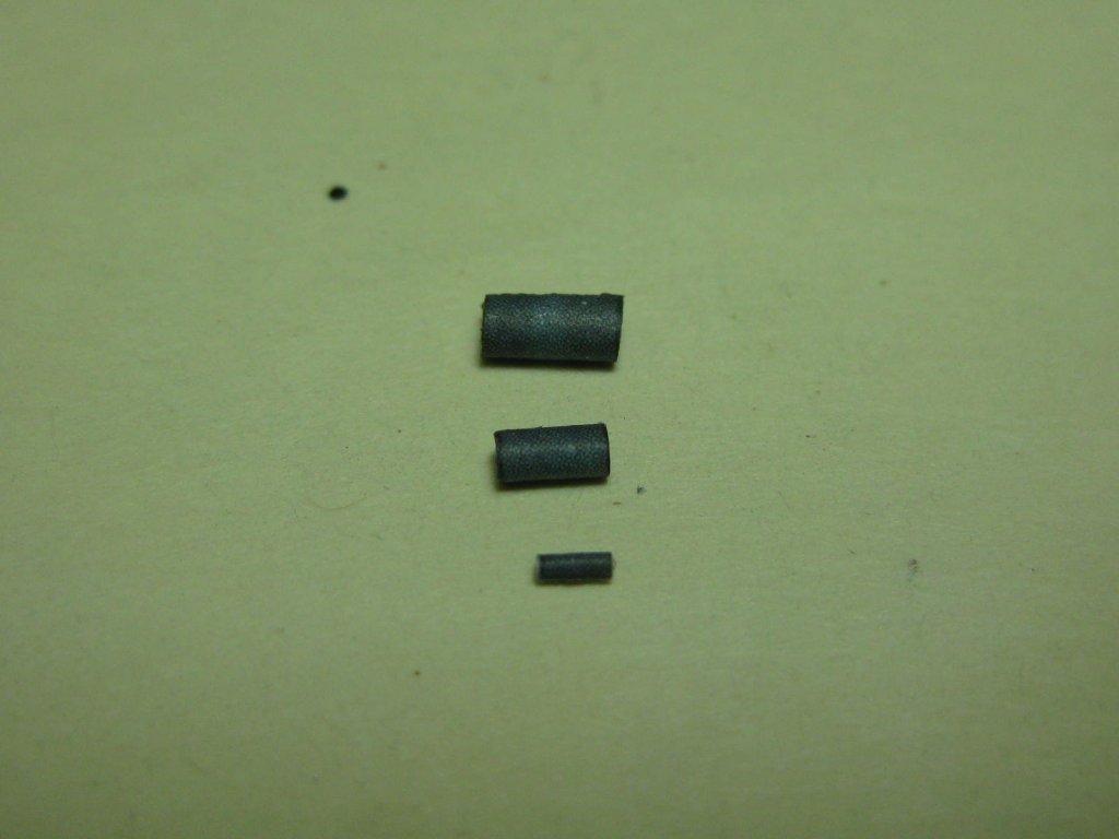
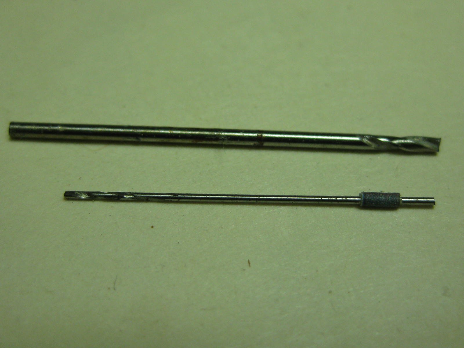
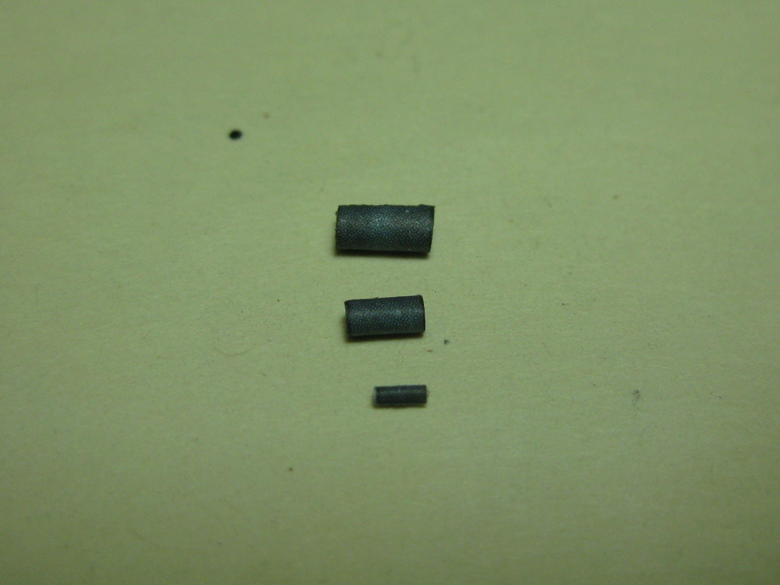
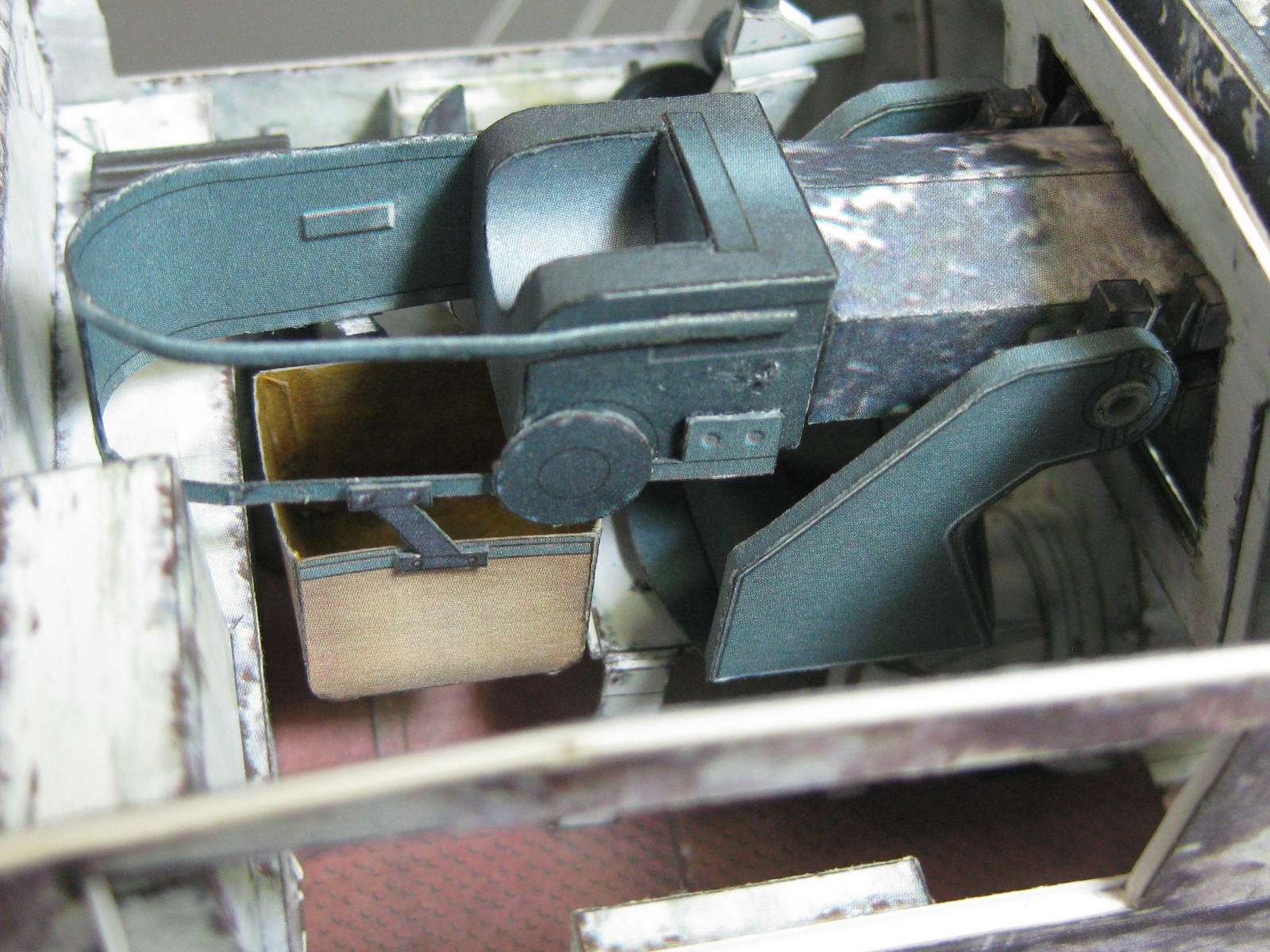
Now we're really getting ridiculous. These are by far the smallest diameter tubes I've ever had to roll - a mere 0.6mm in diameter. They are the handles for control wheels, and are rolled around a 0.4mm drill bit (a 1.0mm drill bit is shown for comparison). The second pic is of three sizes of tube for the gunsight assembly, with the largest being 1.5mm diameter :
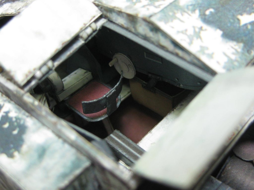
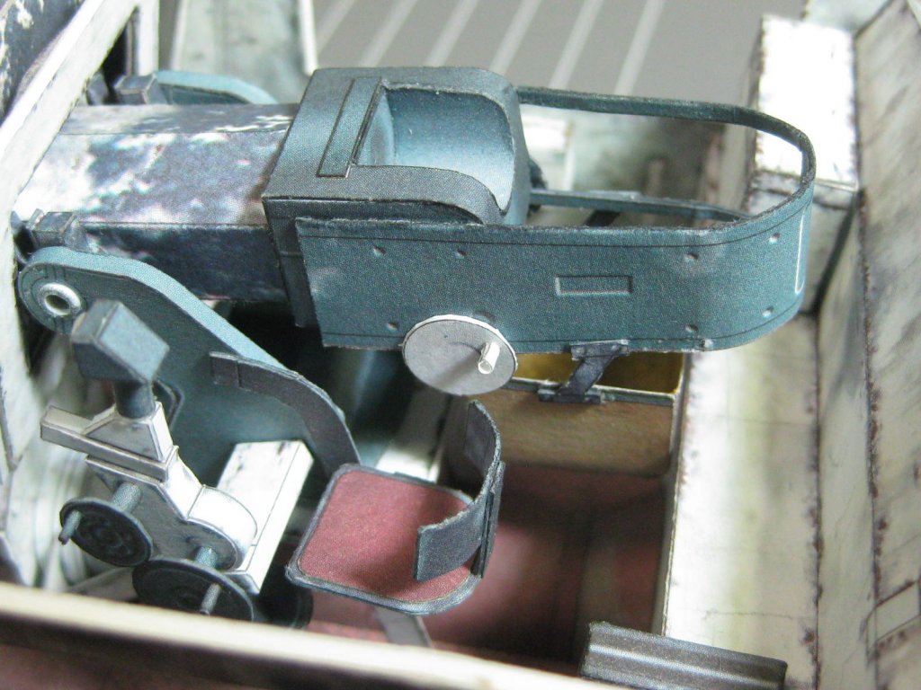
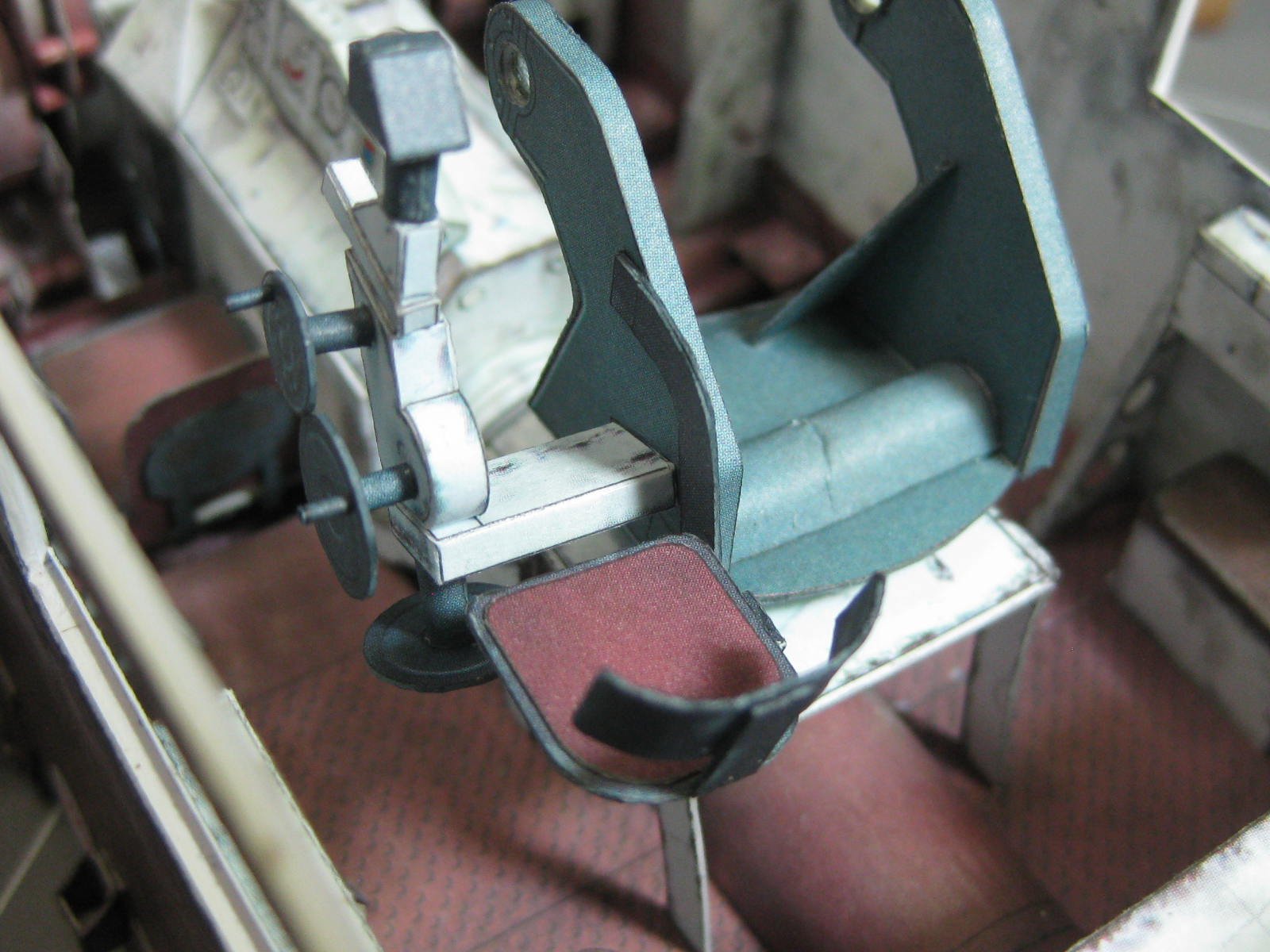
The gunsight and gunner's seat completed and glued in place :
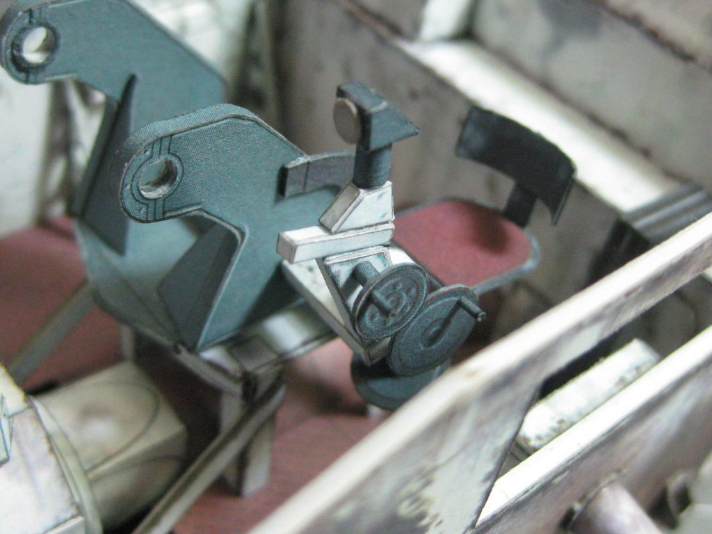
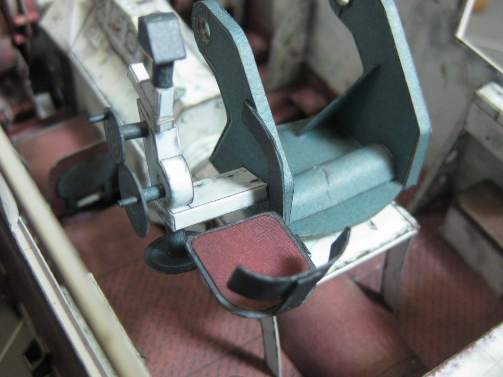
More pieces of the breech fitted, including the catch basket for expended shells :

Danny
-
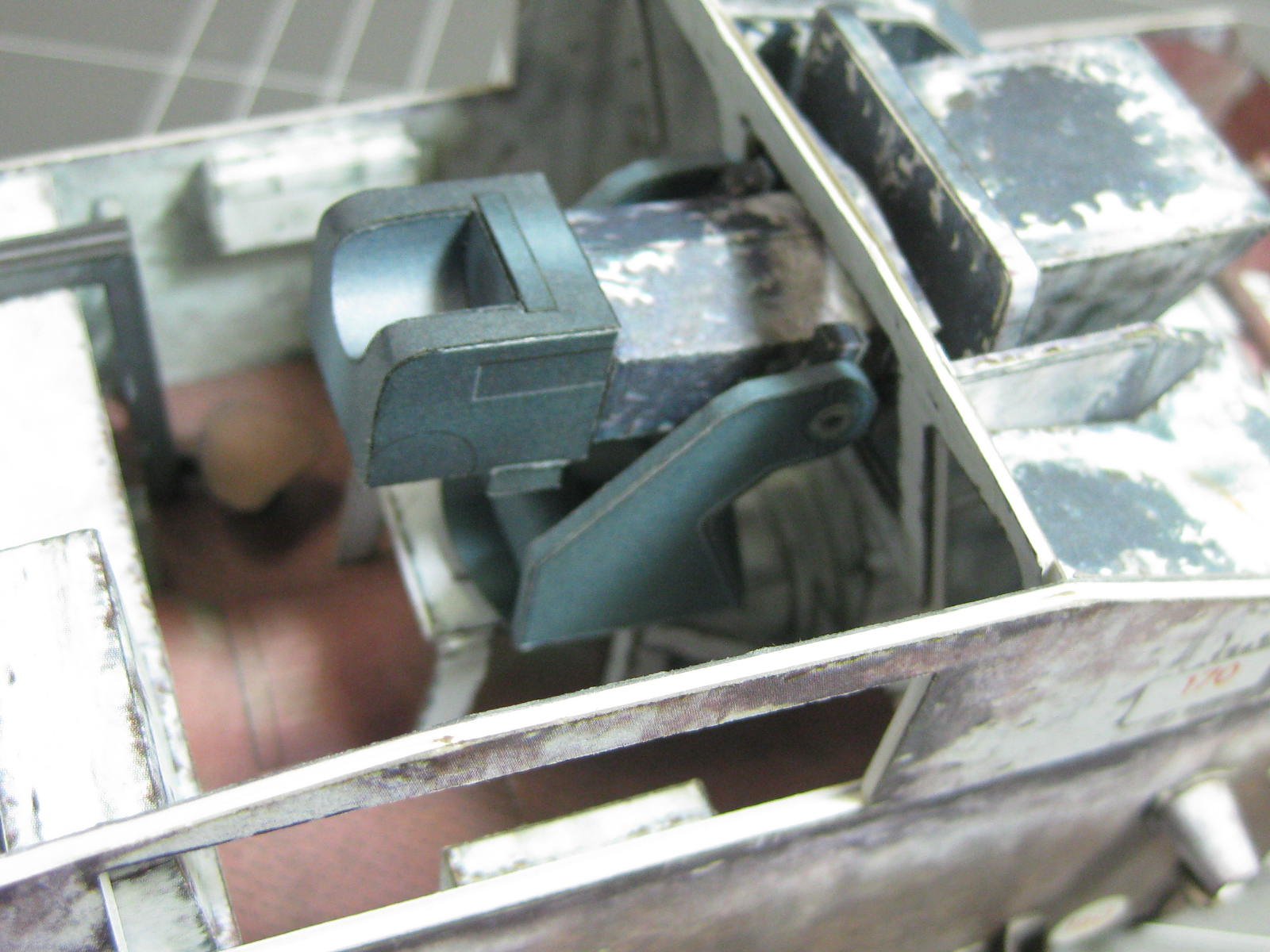
The main gun assembly was particularly difficult to work out due to the VERY poor instructions. I'm not at all happy with the effort, or rather lack thereof, that GPM put into these. Why on earth would they bother "detailing" how to assemble a bucket, axe and German helmet for instance, but show only a very basic drawing of the really complex assemblies? Makes my blood boil 🤬.
Not to worry, I eventually worked it all out
. The pics below are of the breech and the elevation/sweep support bracket. I've managed to make it work both ways. I used a piece of 3mm PVC tubing for the elevation pivot, as the kit probably didn't allow for this assembly to actually work :
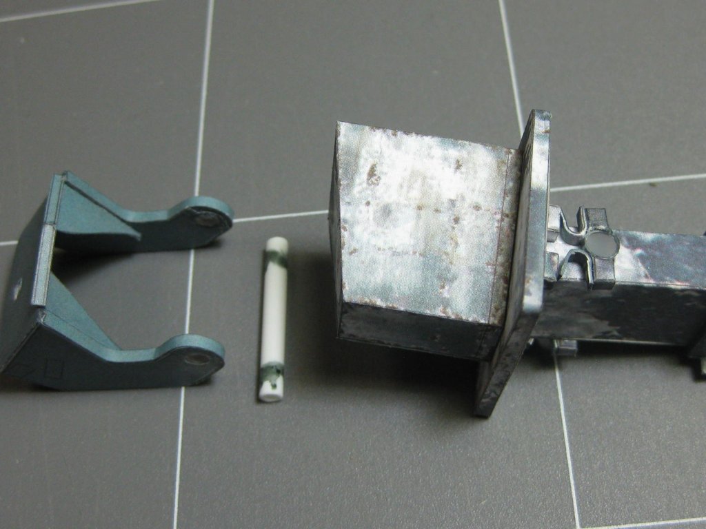
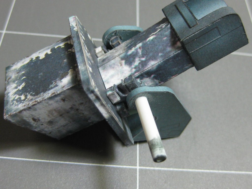

This whole assembly, including the outer skin, is still only dry-fitted, there is quite a bit more work needed before I can permanently mount it :


Danny
-
Thanks for that Adrie.
Danny


Stug 40 by Dan Vadas - FINISHED - GPM - CARD - WW2 German Tank -
in Non-ship/categorised builds
Posted
Thank you all") .
.
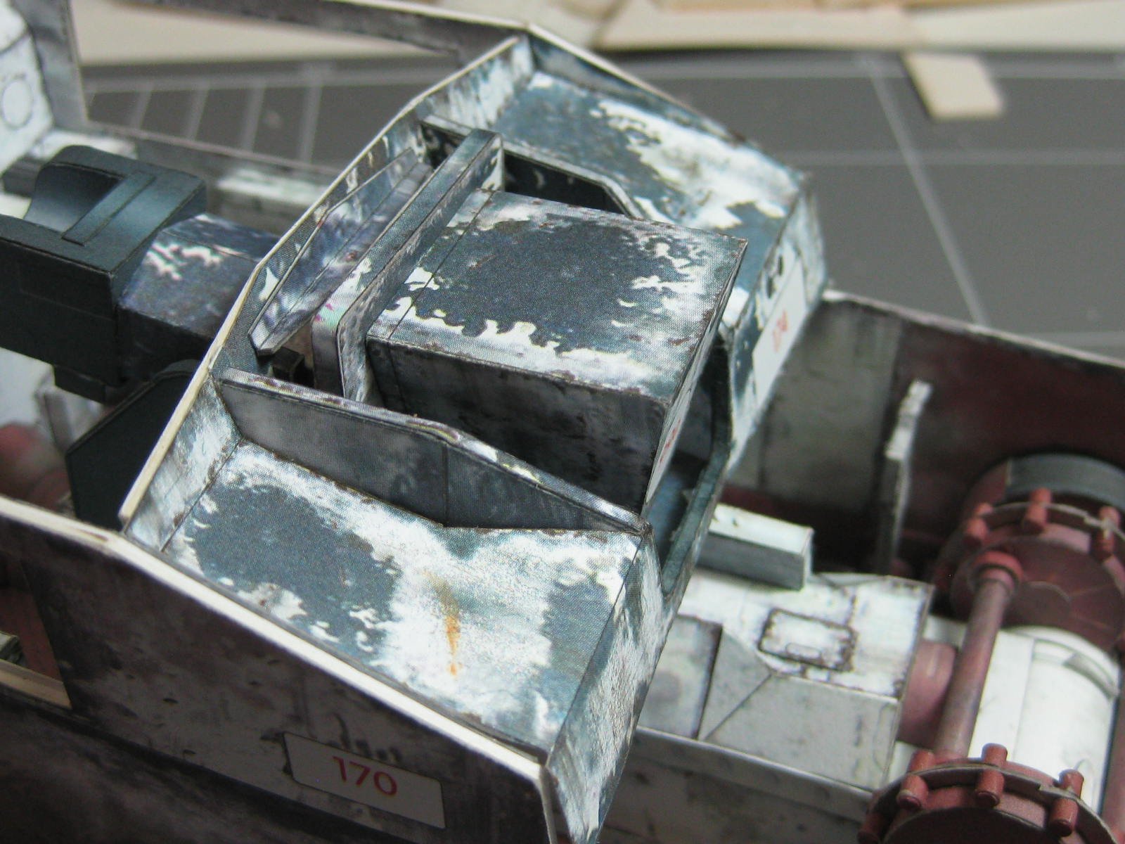
Getting near the end of the build. The last major part - the gun :
All that's left to do are some minor details - a 50 cal machine gun, some jerry cans and tools, etc.
Danny