


Dan Vadas
-
Posts
3,261 -
Joined
-
Last visited
Content Type
Profiles
Forums
Gallery
Events
Posts posted by Dan Vadas
-
-
Thanks lads
") .
.
The forward funnel finished with all the pipework :
.thumb.JPG.da39dad5f5699d467edf877f5f6f64ad.JPG)
The Aft Funnel has turned out a bit better than the forward one - nothing like a bit of practise to make improvements
. I made a few small mistakes with the other one, which I've avoided with this one. Most noteworthy was the fit of the top flange - with this one I notched out for the PE guard :
.thumb.JPG.f61bf1c98022cbb7483399a032855fa1.JPG)
The internal railings also came out a bit better on this one :
.thumb.JPG.5015589b9d70025496ca5b19f39d56f5.JPG)
I also had the main seam on the wrong end with the first one. Luckily I did a reasonably good job of fitting it, so it won't be a major concern. Here's the completed aft funnel :
.thumb.JPG.9c64c9ad20fa69ff75b8ab5581d9bea3.JPG)
.thumb.JPG.3c97fa248a2b144ceb6d62d1fed39cb2.JPG)
Danny
-
Once again I'd like to thank my followers for their kind comments
.
There is a fair bit of work to do inside the Funnels - Walkways and Railings from PE. In the pic below I've painted half of them matt black, as they are a bit more visible in primer :
.thumb.JPG.4a753a7ace5428cb73a8c6c49a97012e.JPG)
All painted :
.thumb.JPG.8ed33df1a0735d3d02f80fc83a32fb1a.JPG)
The funnel guard(?) is a bit flimsy before it's fixed in place. I used the back of a foam sanding pad to shape it with a toothpick :
.thumb.JPG.f33ced5b11d7553a7888c55a74ea22bb.JPG)
.thumb.JPG.0d2f6faf6e2eabda0150fddf0e9caa0e.JPG)
The guard (still in primer) CA glued in place :
.thumb.JPG.45f27a69b93a7862935822ffb3912e16.JPG)
An angled rim covers the ends of the guard :
.thumb.JPG.bb0cb8e9d8ff5b25c9a0f828323f112f.JPG)
.thumb.JPG.7b9d7bf217b008726673c67b654fcf1d.JPG)
The Forward Funnel is nearing completion. I've been simplifying the way I use the laser-cut framing - with experience I've nearly stopped adding extra card to them. Here the funnel is being skinned :
.thumb.JPG.a79d76f8c094c6e4a6e2f05007f20d55.JPG)
And attached to the base I made earlier :
.thumb.JPG.0cf19700bcc8d5785fa01505aed9902d.JPG)
Danny
- FatFingers, RGL, mtaylor and 19 others
-
 22
22
-
1 hour ago, dbar1 said:
Hi guys,
I am currently building HMS Victory and have a small difficulty of a generic nature which needs some help. What is the angle at which the main mast is normally fixed to the deck? I am not sure whether this shld be 90 degrees or slightly inclined toward the stern. Drawings on the plan show the latter but i am bot sure. Thanks for yr help.
Foremast is vertical, Mainmast is inclined about 1.5 to 2 degrees toward stern, Mizzenmast is inclined about 3.5 to 4 degrees toward stern.
Danny
-
Thank you all
.
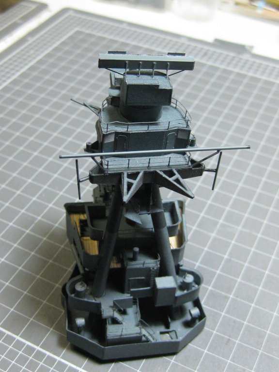
The Control Top is now fitted to the rest of the Bridge. I'll leave the whole assembly off the deck for now in case there are other things to fit to the deck first :
.thumb.JPG.dc8dcb774a422b77bb0646c5db4b2dee.JPG)
.thumb.JPG.1bbb954c0d44b51e895463cde06405bd.JPG)
Now I've moved on to the next assembly - the forward funnel. I've made the base for it, but before I continue there are 5 Rubber Boats to make. These mount on the base.
Here are a sequence of pics showing them being assembled in a jig. I made this to hold the boats while gluing up the sides, as they are very "slippery customers" to hang onto. First pic is of the parts for 4 boats in various stages of preparation :
.thumb.JPG.d879c48766a6e4c8fd4c05457be9c467.JPG)
The Holding Jig, made from card :
.thumb.JPG.80b31645ac1ceff684b47916ac3aba5d.JPG)
The jig in use :
.thumb.JPG.6450607c7d2171c5a1876362bbebac0e.JPG)
.thumb.JPG.b17cb8b23176c574cf152775400f965d.JPG)
.thumb.JPG.b4cf3dd8385004f6bbbd4ed567ddbe4e.JPG)
The boats fitted to the base :
.thumb.JPG.d3b89c0394f3d39ed5e6e92d1b6b989e.JPG)
Danny
-
17 minutes ago, Ryzuhr said:
Am I right in thinking that the brush-tip ink pen is run along the edge of the planks (before being glued down) to simulate what it would look like if they were sealed, as if on the real ship?
Exactly Andrew
. On the real ship they used hot tar. There was a gap of approximately 1/2" between the planks to accept the caulking.
Simulating the caulking also delineates the planks on the model, making the individual planks easier to see. Don't overdo it however, "less is more" in this case.
Danny
-
Thanks for all the kind comments guys and gal - they are always appreciated
.
Moving upward, another platform with 6 binoculars among other things :
.thumb.JPG.e736008239f094a5c2646aea2619728a.JPG)
.thumb.JPG.402acecd57fe39f9f890722f1795e57d.JPG)
.thumb.JPG.beee0edd9322048627ac4b62fd93bf9f.JPG)
.thumb.JPG.50b6f839c377ea7383232678b7780c87.JPG)
.thumb.JPG.2a88977e13408e4e55976c73a52d79bb.JPG)
Next came the Foremast. To roll the legs I used a piece of brass tubing lined with thin card to give the right diameter :
.thumb.JPG.5b81898d828c9309f45a5e66c921dbb9.JPG)
A #16 drill was the perfect size for the inner diameter. I glued the seam a little at a time, moving the mast in and out to prevent any excess glue from sticking to the card liner :
.thumb.JPG.481be3b704c758763b5f83bc960a3540.JPG)
The three legs glued together :
.thumb.JPG.c404ee1c132fe00b7969ab48c736a797.JPG)
The mast fitted to the bridge, along with railings and ladders :
.thumb.JPG.331cbfc739598218cc12263345638b01.JPG)
.thumb.JPG.68d9600150a1f77ec71981ddec88390e.JPG)
.thumb.JPG.f6349419c964bc13e5c21683c550f8d9.JPG)
.thumb.JPG.c4fb7082d6022dcd3dba7757ba02192d.JPG)
.thumb.JPG.1c993c0e020367a49b31fad9ce6af7e0.JPG)
The Fore Control Top sits above the bridge. Cutting the flimsy base for it took some care :
.thumb.JPG.d50ce8eb74ea6c1b1247e94cdf81b608.JPG)
.thumb.JPG.f9e5fe53870482aa68eeb585b5432e9a.JPG)
PE Radars came with the aftermarket stuff. Here they are ready for paint :
.thumb.JPG.092495f8402bd79c4993e26fe25f1b32.JPG)
.thumb.JPG.63dd344be4700c3a84cee14a1ea8bf88.JPG)
.thumb.JPG.0875231373cf000de9e058a0eb812ddd.JPG)
.thumb.JPG.5bc3294d62d4c4d9ae5870794ca05548.JPG)
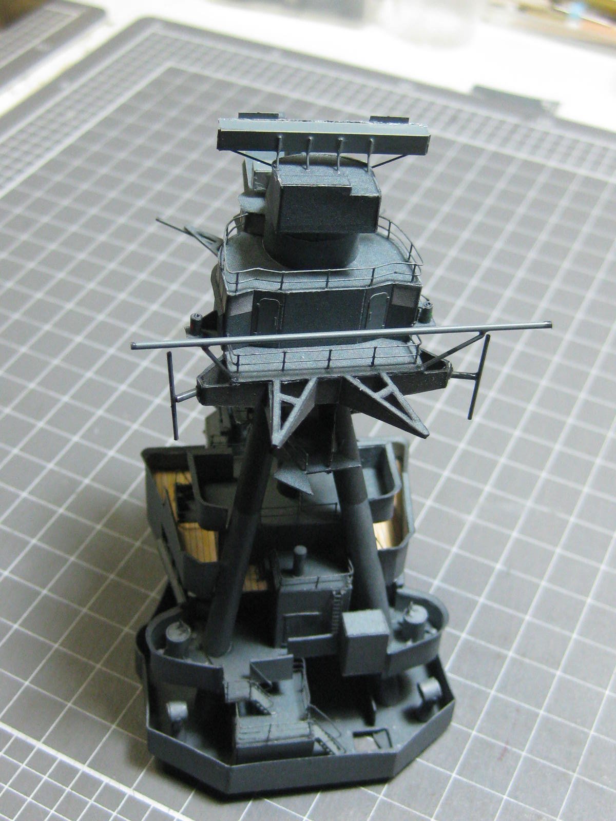
Radars fixed to the top :
Railings and antennae fitted, and the top permanently fitted to the bridge :
.thumb.JPG.aa7ce8cd5b4b90bf5c0b3d7dc02cbedc.JPG)
Danny
- Fernando E, BenF89, gjdale and 20 others
-
23
-
-
-
-
Here's another tip for you. Stack 7 or 8 planks together, tape each end tightly and edge-sand them all together using a sanding block until all rough-sawn edges are smooth and the planks are an even width. Taping them together makes the stack more manageable.
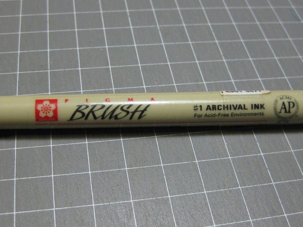
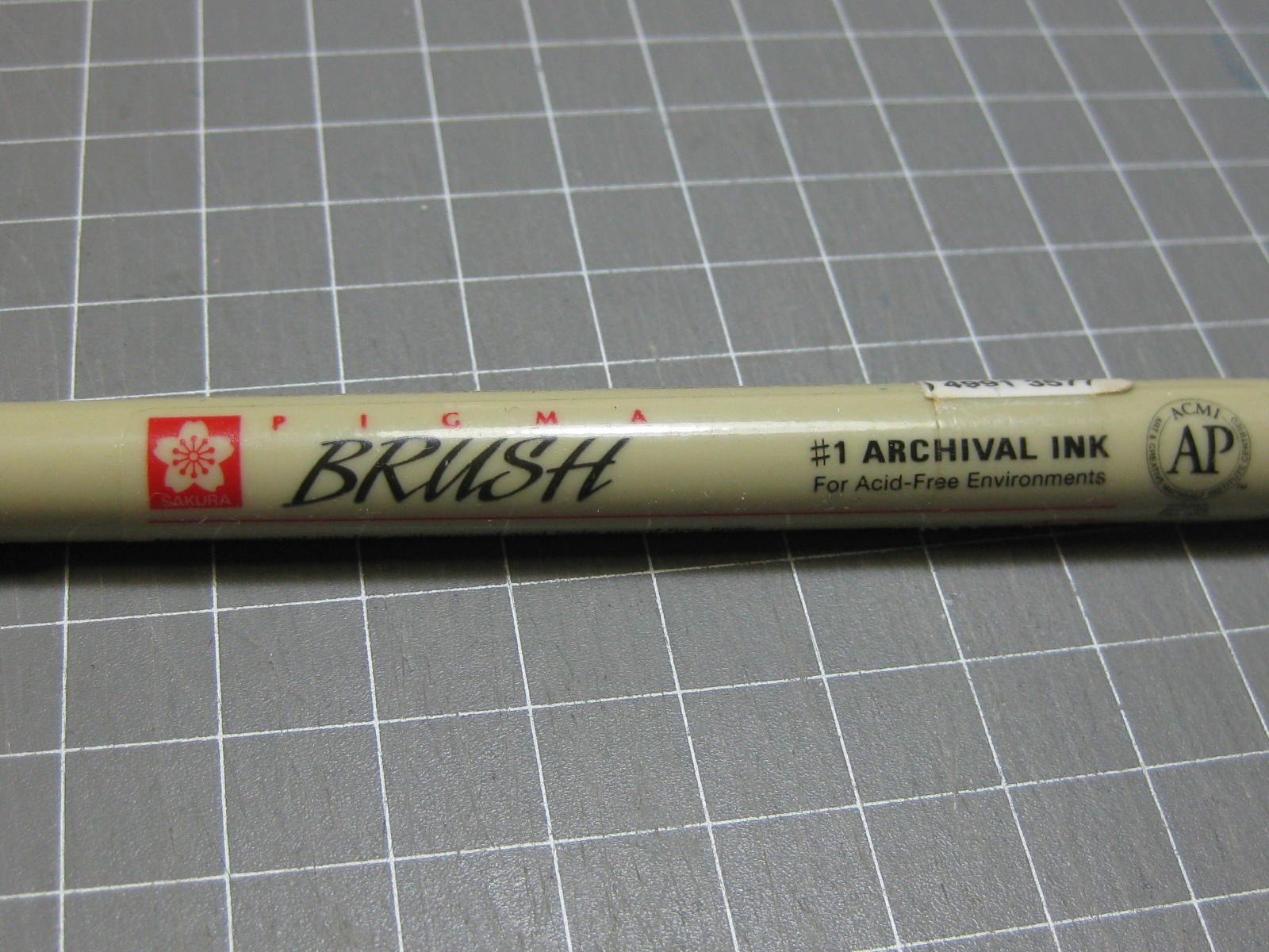
You can also apply most of your "caulking" while the stack is still taped up. An "Archival Ink" pen works very well for this, as the ink won't bleed like a regular felt pen. You can buy one at Eckersley's Art & Craft in Hamilton, or maybe at Office Supplies in Newcastle West. Get the "Brush" tip style. They're not cheap, but worth the extra cost.
Danny
- Jim Rogers, Zarkon, lmagna and 4 others
-
7
-
The two tiny pieces of planking between the mast and hatch are exactly what I was talking about before - NO WAY would the real ship have been planked like that. It's not too late to pull them up and replace them with a single piece.
Danny
- Johnnyreg, Zarkon, paulsutcliffe and 3 others
-
6
-
Thanks John, and welcome home
.
The Bridge is quite complex. So far it's taken me over a week to get as far as I have below. Here are the pieces that make up the framing :
.thumb.JPG.3e79c827066583306d2e6f59cd544ea6.JPG)
There are also a number of platforms attached to the sides :
.thumb.JPG.35d09100c4a30c936aa314aa285e6383.JPG)
.thumb.JPG.c9e09cdbf2bd4aaeb274f7960e925242.JPG)
.thumb.JPG.2e2fe57f2ab9e36995c810da03e05eae.JPG)
Lots of small fittings, some of which I have no idea about their function :
.thumb.JPG.f978a1933d483ab60e02093c9b00b48e.JPG)
.thumb.JPG.bd7eb73672e44827ffcac87a38ae0f2e.JPG)
There are also a few stairs :
.thumb.JPG.e2053e6afabb60b0cc73c85b528ec915.JPG)
.thumb.JPG.e0fd059b60e39613226cf1bd285fb1b6.JPG)
.thumb.JPG.935b8e09402bd7310b9bd50cb885b197.JPG)
Some overall pics of my current progress :
.thumb.JPG.f63d4ce071f9a93fb4f4fb80b72125ed.JPG)
.thumb.JPG.5e7baba8a187a63e1e5d37712b9ef6d8.JPG)
And finally one to give an idea of scale :
.thumb.JPG.a80e68df4596771c945e3add06e9ca10.JPG)
Danny
- egkb, Old Collingwood, mtaylor and 22 others
-
25
-
Regarding the difference in length of the quarterdeck. Supply as originally built (as per the plans above) had a short deck which was extended before her journey with the 1st Fleet to Australia. She was also re-armed with 4 six-pounder guns and four carronades. So it really depends on which version you want to build. The Jotika/Caldercraft kit is reasonably close to the 1st Fleet version.
Thunder's point on the planking between hatches is a valid one. Full length planks (20 to 25 feet) would have been used wherever possible with no butt joints between hatches over this distance. The 3 or 4 shift pattern would start from the first planks outside of the hatches. From memory Supply used a 3 shift pattern, 4 or 5 shift patterns were used on larger ships.
Danny
-
The next platform didn't take long, about a day.
.thumb.JPG.12a5e26327fcb33df5f46caed2bdac06.JPG)
I've worked out how the stairs fit, after a bit of trial and error. The instructions only give you rather vague renderings of the finished articles - some forward planning is needed as regards the next deck. Some stairwells have another level or two above them, others don't. The treatment of the railings is different depending on whether the stairwell continues or not :
.thumb.JPG.d3bbe5fff47d29abbd6b1ac252c35f6d.JPG)
.thumb.JPG.6f631635effd04fee8af27248b69a89a.JPG)
Danny
- coxswain, hexnut, Tigersteve and 18 others
-
21
-
The deck sheet may not match the capping rail perfectly either. Use the rail to get your final shape - don't forget to allow for the thickness of the planking.
Danny
- Jobbie, Johnnyreg and paulsutcliffe
-
3
-
Thanks again guys
.
I realised that if I were to fit the next deck above this platform that it would be virtually impossible to fit the 5 ladders, so I came up with a simple solution - I tack glued a piece of scrap card under the platform that served two purposes. First it gave me a height to work to, replacing as it were the main deck, Also it protects the ladders from damage at the foot of the steps - these would easily be wrecked as I moved upward. I won't be fixing the Admiral's Platform to the main deck for quite a while yet as it's a lot easier to fit all the decks/platforms on the bench rather than on the hull. I will glue the whole unit comprising about 5 levels to the main deck when they are completed.
.thumb.JPG.0356d307e7eae2101eb19441f155f7c1.JPG)
.thumb.JPG.a845dd0f47cdecbe05533c93a67bce51.JPG)
.thumb.JPG.4ef67094124dbb440c80aefdf40989aa.JPG)
Danny
- hexnut, BenF89, Fernando E and 21 others
-
24
-
7 hours ago, amateur said:
I am a bit struggling to see where the cardboard ends and the PE sets in with the guns.
Thank you Jan
. You can't see any PE in the guns because there is almost none - only the two handwheels are PE, the rest is paper except for the barrels which are CNC lathe-turned and 3 pieces of wire ") .
.
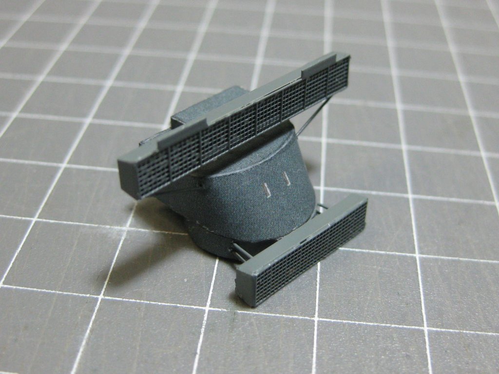
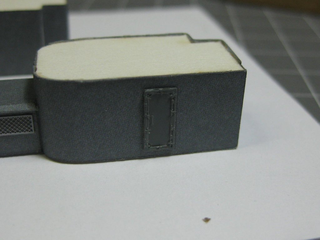
I almost forgot about the two HACP (High Angle Control Position) towers, which I made last week. These took some building - two days in total (no progress pics, sorry) :
.thumb.JPG.f50fb168e00a481adb7216a7e41d4fb7.JPG)
.thumb.JPG.0b130870742aa4f02b5bc6321817e219.JPG)
The Life-rafts are a pain to make. These are my first two of 16, hopefully I'll get better with them as I make a few more. They are 12mm long, the one on the right is still to be finished :
.thumb.JPG.4489b8f22d202c79e2a5fffaf610b591.JPG)
.thumb.JPG.1eae5b56025c1a4151f224607cc2c279.JPG)
An overview of the platform. The only things remaining to be done are 5 ladders (you can see the two railing posts at each entry), which I can't fit until the platform is fixed to the deck :
.thumb.JPG.b6707572f47f01f896963496c6d42677.JPG)
.thumb.JPG.0d518231a69a1f199fe43345e16f70fa.JPG)
Danny
- Canute, marktiedens, Tigersteve and 11 others
-
14
-
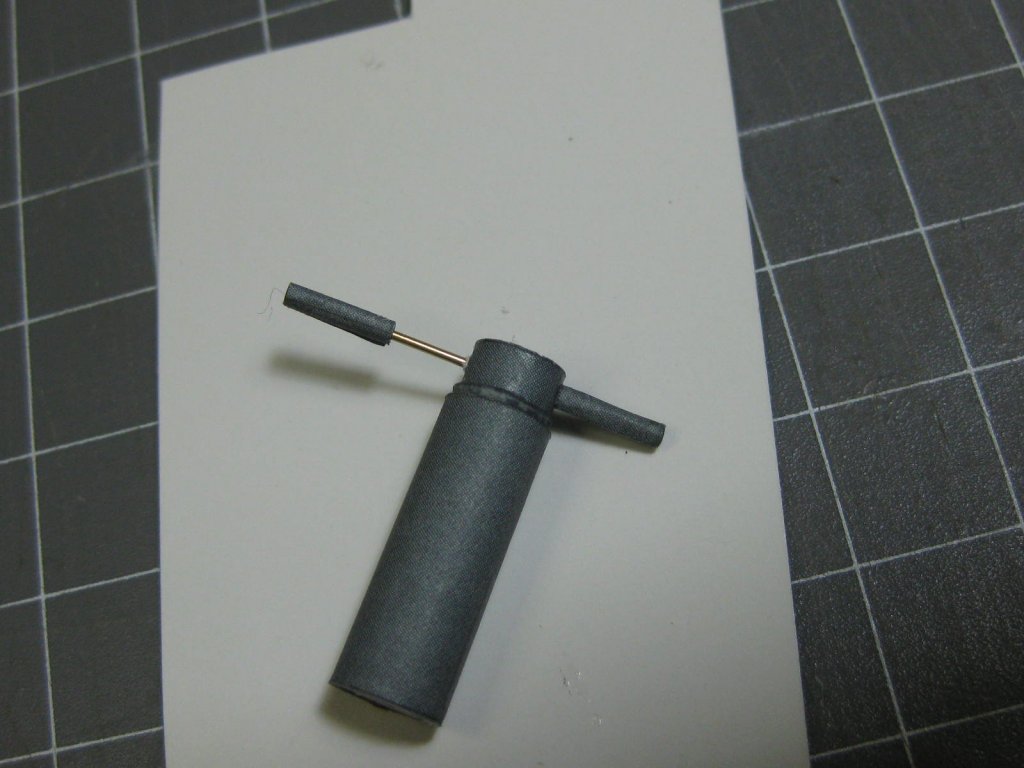
It's been a while since my last post - I've had the 'flu and build time has been reduced a fair bit. However I've soldiered on and got the Admiral's Signal Platform almost finished.
Here is my technique for gluing on the arms of a Range Finder. The wire not only strengthens the joints but also ensures the two arms line up with each other :
Some more ridiculously small parts - the box is 1.5mm square :
.thumb.JPG.c026fa161781c27a9830094a1b9b120e.JPG)
.thumb.JPG.c9b3418ed66010fcd495c0aa0b6732cc.JPG)
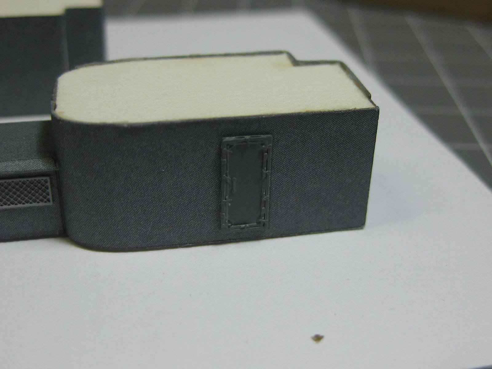
I finally worked out the right way to assemble the water-tight doors (no instructions in the kit, but I found a good drawing of them in AOTS Hood). the doors are made from three pieces of PE - the door itself, an inner panel which has the lock wedges etched in, and the outer panel which has the locks and hinges on it :
.thumb.JPG.0b669f4b10ed2393ccf838a2139d1762.JPG)
.thumb.JPG.11a0422b00c020cae1e37a66b917696e.JPG)
These are the 12.7mm 4-barrel machine guns. They look difficult, but I made all four in a day :
.thumb.JPG.09432330f6ec33f867284d14c1c462fa.JPG)
.thumb.JPG.082c7e34f0a53fb5895c55a2f1eb9304.JPG)
.thumb.JPG.dd8fcc876c3b83ac34a6a03d255aa0b0.JPG)
.thumb.JPG.7215337e8340af5a95469abe3058dd5b.JPG)
.thumb.JPG.c0063e9a820c07758d5cf18af650b1e8.JPG)
The Admiral's platform up to date. There are still a few minor things to fit :
.thumb.JPG.802e98b6cfe9a336bcd4771c045aba9b.JPG)
.thumb.JPG.0a7032444244c2eadf3bb0917c6cb643.JPG)
.thumb.JPG.274e2561bcf30afd68577dbe9c067911.JPG)
.thumb.JPG.f55438a9dca3a0b9af9a1fd7efdce1db.JPG)
Danny
- Old Collingwood, herask, Canute and 21 others
-
24
-
Neither. It should be a smooth round curve, the deck seems a bit flat in the 1st section. Your fillers definitely have too much of a bulge.
Danny
- Jobbie, lmagna, paulsutcliffe and 1 other
-
4
-
-
A good move Jeff. HMS Victory is probably one of the most complex models one can build, and is really NOT a beginner's kit. A step back is a good idea, go with something that will teach you all the skills but that you can finish in a reasonable amount of time to get the satisfaction of completing your first wooden ship.
You can always come back to Victory in the future. I did exactly the same with my first Victory (which was actually my 5th or 6th wooden model) when "life" also got in my way. I took a 10 year break from her
.
Danny
- Tigersteve, Old Collingwood and Zarkon
-
3
-
Way to go Toni, much better
.
Danny
-
A half hour drive up a highway and it's not even a tall ship? Phhht
. She'll be right mate, back seat of the car will be fine  .
.
I've moved a 1:96 HMS Victory over a windy mountain road in the FRONT SEAT of a Toyota Pickup truck without damage. Although I couldn't use 2nd and 4th gears because my elbow would have broken off the bowsprit
 .
.
Danny
-
6 hours ago, popeye the sailor said:
are you using another of the archive pens to touch it up after? how much of this will you / we actually see?
Popeye, I use the archive pen as soon as a piece is cut out. I've found it's nearly impossible to do any edge colouring with the pens if they have come in contact with glue. Look closely and you'll see all the edges have already been done
.
You'd have to stand on your head and look VERY closely to see any of this detail
 .
6 hours ago, ragove said:
.
6 hours ago, ragove said:Your eyes must be like magnifying glasses.
I wish. My eyes are just about shot
.
Danny
.JPG.60df6cf1e9bcdea2d5950bbf55b2ea5c.JPG)
.JPG.d36c15ff7efb41f3d0bd5c9f9e187350.JPG)
.JPG.007492710154e5fb6160a41b7c2ab3a6.JPG)
.JPG.584fd8a24688c0baf2aa7b4ac233b582.JPG)
.JPG.50ceae40f5eacbfc9527dccf9a9fbbdc.JPG)
.JPG.e71de8a7a5dbd3f7e2329a5458d3dc6f.JPG)
.JPG.04f525933d2da1dcb8cd11e938ec7106.JPG)
.JPG.fc6df5ec2c5901e33933cab6d941662c.JPG)
.JPG.bb5371e3ed3892f479ac7e3830581c58.JPG)
.JPG.dd40cf5124f61ce7818999e1129cfdd9.JPG)
.JPG.3f3faf302ccb7e0dce1c8a33e7dfd759.JPG)
.JPG.33479e660c01b23ea4d54ba934baf74b.JPG)
.JPG.7937b0d49b5105bf9c1a1fd835027186.JPG)
.JPG.4c224dd63be5233a1418830ddaa6c9cf.JPG)
.JPG.35cbfc3c775aa75a22c6aa85efcbd318.JPG)
.JPG.105a38be79b54e1a6924b0ceba2d6356.JPG)
.JPG.ccd080eba7df93601c72cfb7ba905fae.JPG)
.JPG.d0f23d3a2ef6f080e3f006edb6f6add3.JPG)
.JPG.8db7b7306f3cf6cb5cc4e34dbcc54064.JPG)
.JPG.e799b64f333ed4f615350f281d311215.JPG)
.JPG.2c3e9d1eecebf3a0d98584dd8e86899c.JPG)
.JPG.bb017375bd69253384183aa611195c0f.JPG)
.JPG.f6c2a664227b72547cfa1996c361dd46.JPG)
.JPG.13705d6188fb40673a7d114dc2ff3827.JPG)
.JPG.8b29970a68b162f29a9e56ba3eb03352.JPG)
.JPG.82108f5d77d31856ef4251cb07706ab9.JPG)
.JPG.d6821a3303334d409de63732f1d4dd90.JPG)
.JPG.345360bb7101dff8f4a1742832a78116.JPG)
.JPG.e760bae004dadd454ad9d1cd577dadb3.JPG)
.JPG.954ab49aae931c8820f6e82da32e0c4f.JPG)
.JPG.ca5b4f4fcb5d4af018464f529aec865a.JPG)
.JPG.bb9876196ae61f42a89e26fc5bf0d800.JPG)
.JPG.ababb8542fcbfafc25bc1ac80bc3f56e.JPG)
.JPG.720ee161a734d9909c97fad15690b7bb.JPG)
.JPG.426b72a18662f74313e409c60812c68a.JPG)
.JPG.bb0c81bb782226489a3e8b471764fb05.JPG)
.JPG.c2b59fcc1ed53f6b47f6243edaec00d4.JPG)
.JPG.5b19bc408d56d09fb7169d1d5b08408d.JPG)
.JPG.bbf840301577c39c6d0f5b6dbb65f9f4.JPG)
.JPG.9e17bb327e7d31546f2e3c8a30f7b212.JPG)
.JPG.315ec33c96ce21c641429d293438c118.JPG)

.JPG.3ad8f318734aa78787080913dd5e19a2.JPG)
.JPG.cf347cbc94b02fe61122c04e7a6051d1.JPG)
.JPG.59357481929919d39f5df72d28569512.JPG)
.JPG.7a004815a4c9a2020e802356a5cf54d8.JPG)
.JPG.61b796c71017b2c528e37686f7878075.JPG)
.JPG.70aab35e85b019d93a7560142a7c7793.JPG)
.JPG.bfb113a31b393eb6c3c317d466e25d2f.JPG)
.JPG.c463fd79deb3607b6474f8d47b1e2ef7.JPG)
.JPG.37dd4eca6fbe2a2cf268afe608174c74.JPG)
.JPG.180a99f7eb820c268001ebb6bcf37d34.JPG)
.JPG.a55f14384af13cf407e5c4ec3c2ebebc.JPG)
.JPG.ae4346bf593ff99c7c78f77faf9bdcc6.JPG)
.JPG.704f56fd1db29c8ff19374f8550b1d7d.JPG)
.JPG.3f4b3dff8e0d8371abddc30478a51b6d.JPG)
.JPG.b2301ca03947bada5ae034ecb850bbc3.JPG)
.JPG.58bb66c644af74ee1233a7d2b13cc63a.JPG)
.JPG.5c9446e80bcd21f512344e311b48f51e.JPG)
.JPG.a0e06c346d56712527d05095ec41f88b.JPG)
.JPG.2e18b98afe2376ed94bbce152e263f16.JPG)
.JPG.a149198d74b02f208945f98854ae2b87.JPG)
.JPG.ade3ad2a1e6a2a47af07d4b3c5730638.JPG)
.JPG.b724a6a91159e83053b4268d9a224a57.JPG)
.JPG.a0f5d79cc94902b4b06820b948c18fc3.JPG)
.JPG.c67dea64c422cc397339cd425dca2b77.JPG)
.JPG.dd59b44b543cbd610a3f3f7fac5a1cc2.JPG)
.JPG.77a585152ab2f116b33d3299543d6646.JPG)
.JPG.67ab58ba7cbbcd0bb3b900293224d08d.JPG)
.JPG.d5fda006941b9c91d6b3050fd448ac40.JPG)
.JPG.04d3a006f56bbc877ddb6a27df5bb234.JPG)
.JPG.5d2511ad0e573e39f8dc5069eaed7a48.JPG)
.JPG.0122c3a71e4ecf71aa6b2c0b97a2522d.JPG)
.JPG.023ba0789202022dc58daae6846489eb.JPG)
.JPG.63e2d7f71eefbdc02ece2b7d12891d2c.JPG)
.JPG.8c0472b64bb2cc7fbbfb5b98776f1fa2.JPG)
.JPG.d21c6675ac7f44e8ea56114a03afa8a7.JPG)
.JPG.6e67f065ef637b763d3bb2848a0716c2.JPG)
.JPG.650153552d394b24b225f369200cd723.JPG)
.JPG.f5edb3ca7b540d2931a1d7618941088b.JPG)
HMS Hood by Dan Vadas - FINISHED - Halinski - 1:200 - CARD
in - Kit build logs for subjects built from 1901 - Present Day
Posted
Thanks for the comments guys") .
.
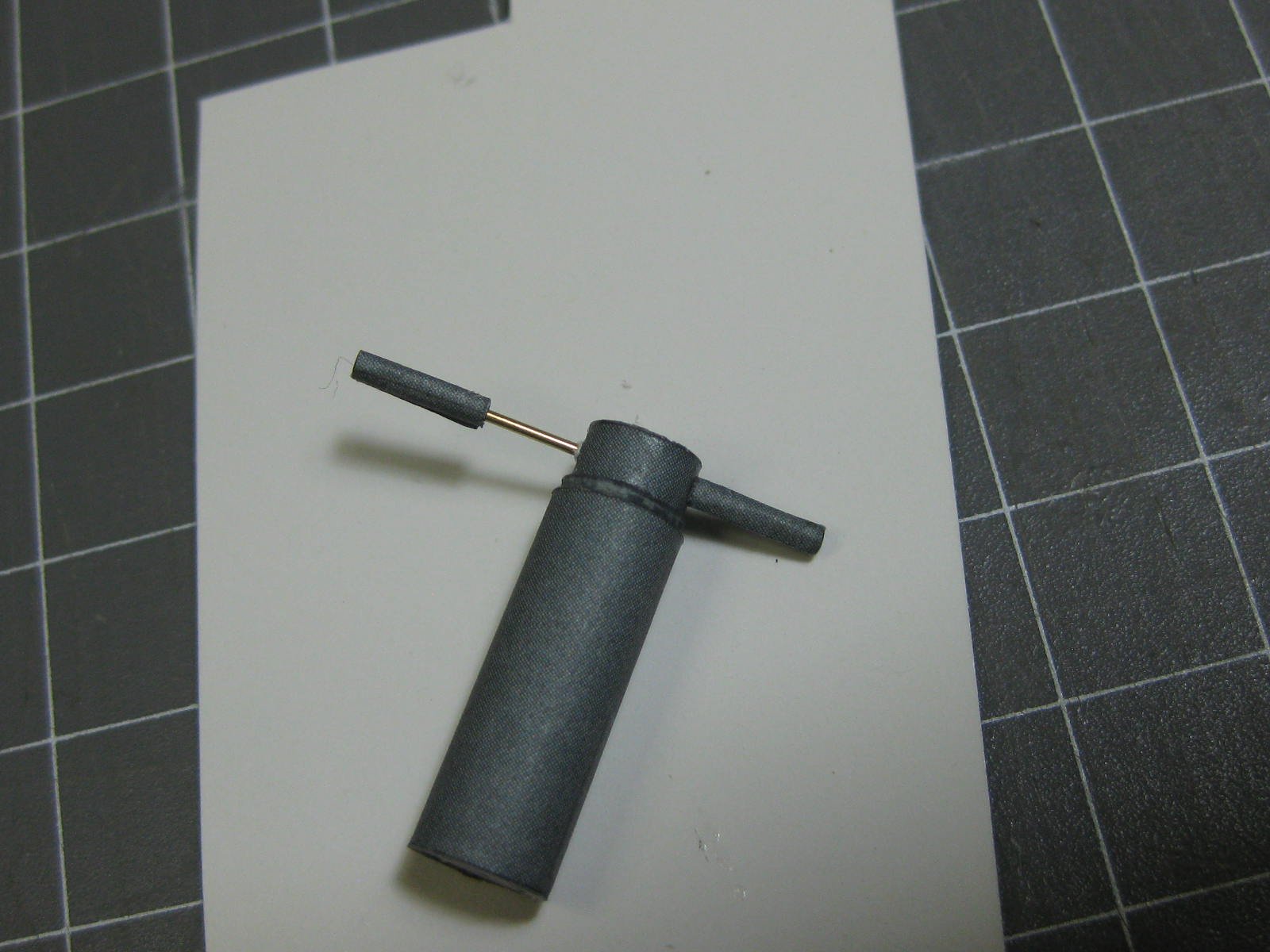
There are two platforms which fit either end of the aft funnel. These have a number of small fittings. Here's a couple of pics of how I roll the gearbox of a winch using the cutoff eye of a needle :
The two winches sit atop the forward platform, here are the parts for them and a pic of the finished articles :
On either end of the aft platform are two Searchlights, consisting of about 16 parts each :
The aft platform ready for fitting to the funnel :
The forward platform also finished :
Danny