


Dan Vadas
-
Posts
3,261 -
Joined
-
Last visited
Content Type
Profiles
Forums
Gallery
Events
Posts posted by Dan Vadas
-
-
Thank you David and Richmond.
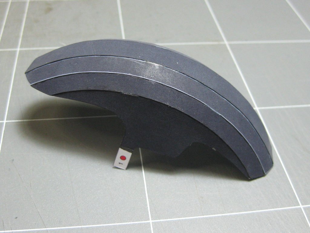
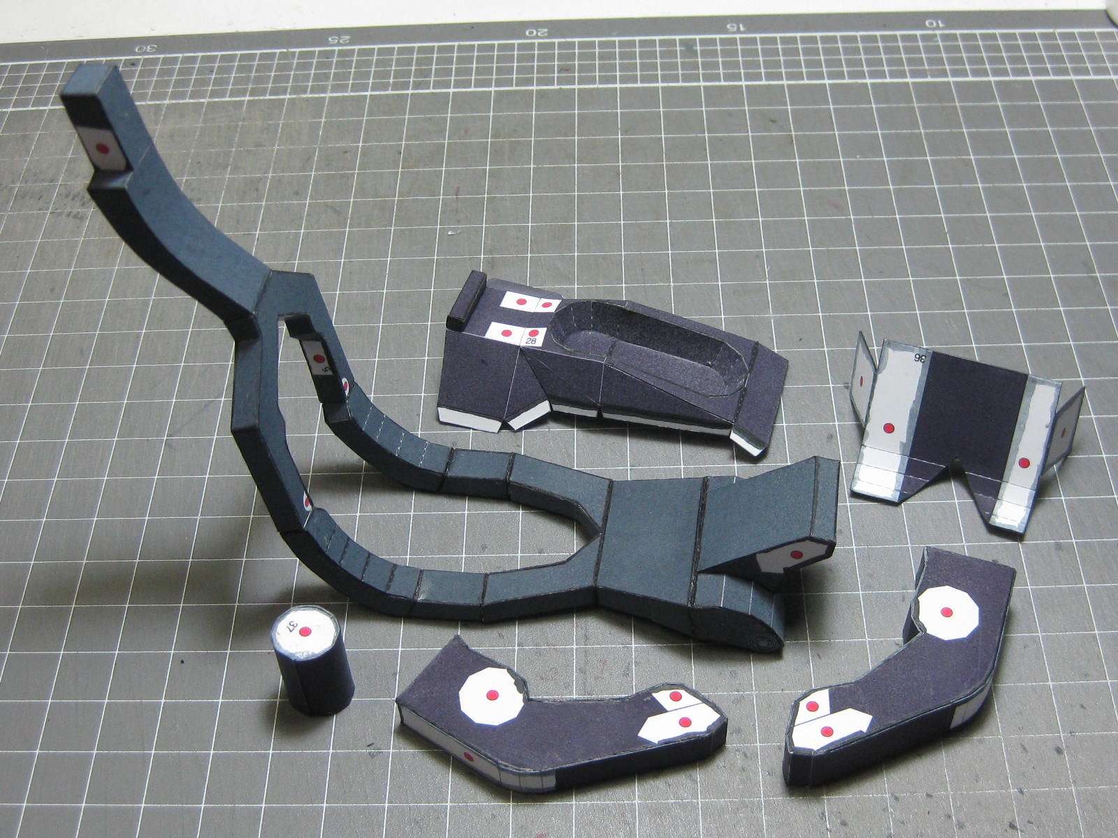
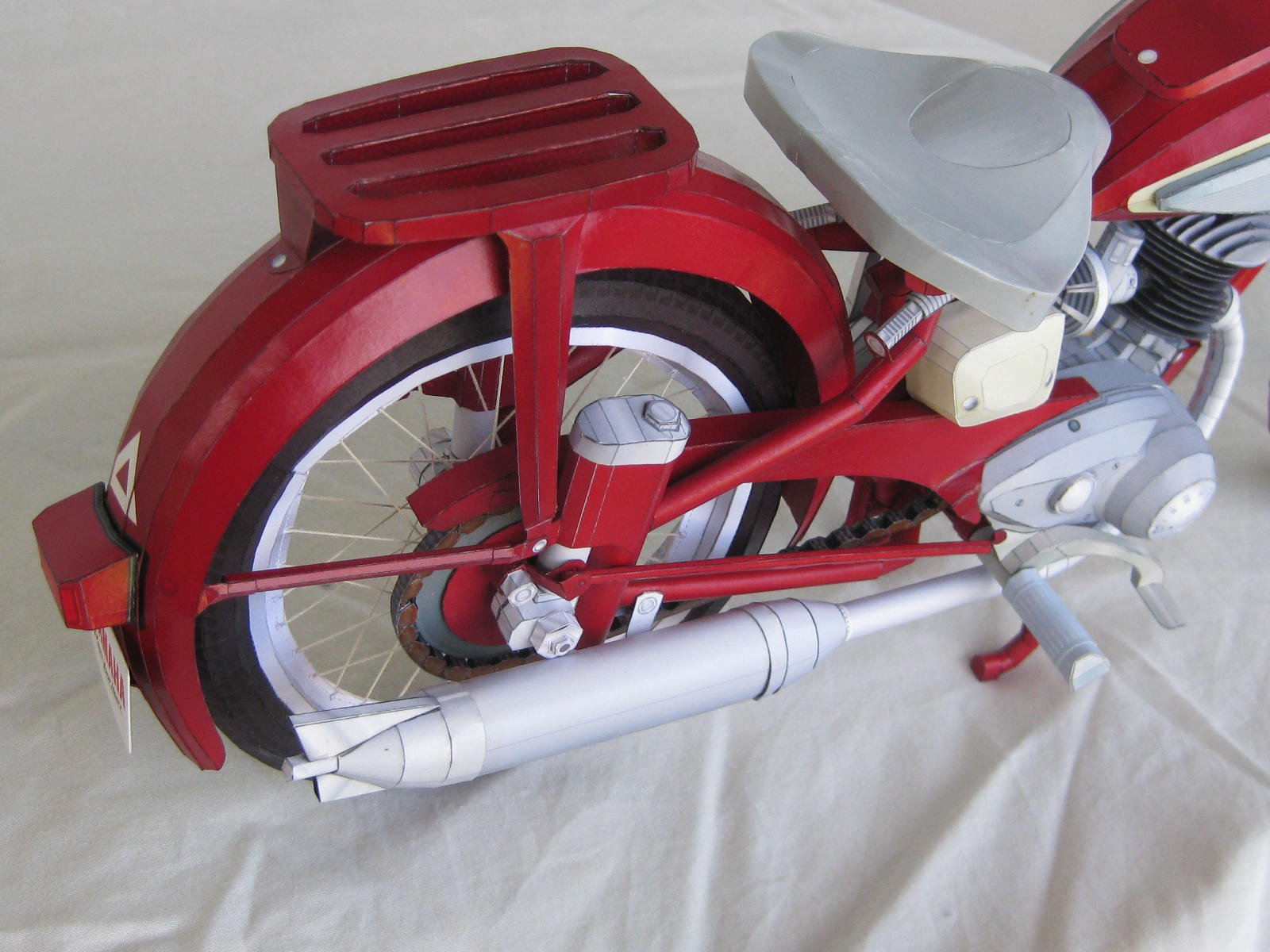
The completed rear suspension, chain and it's guard and the lower mudguard :


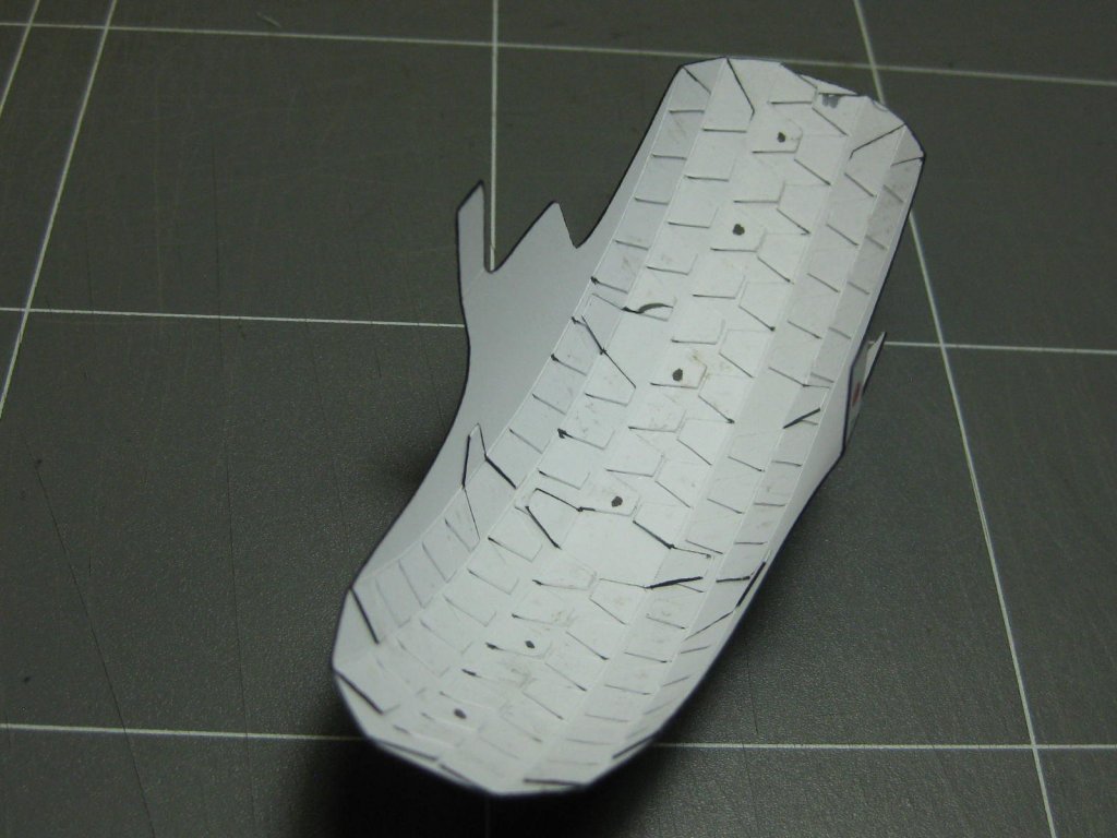
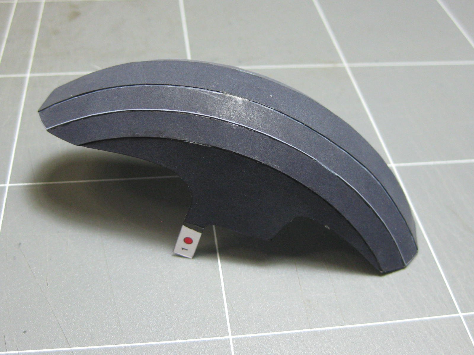
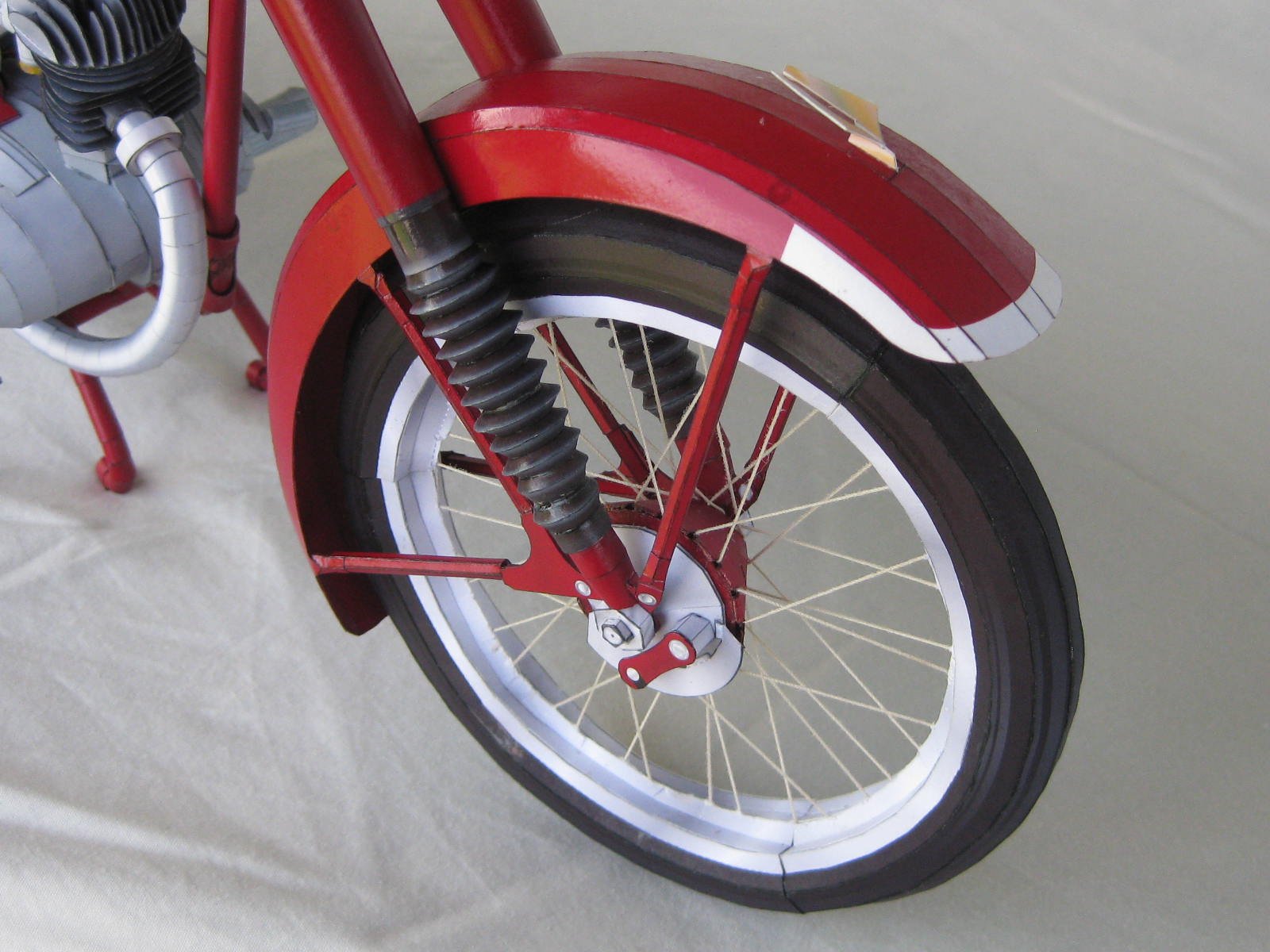
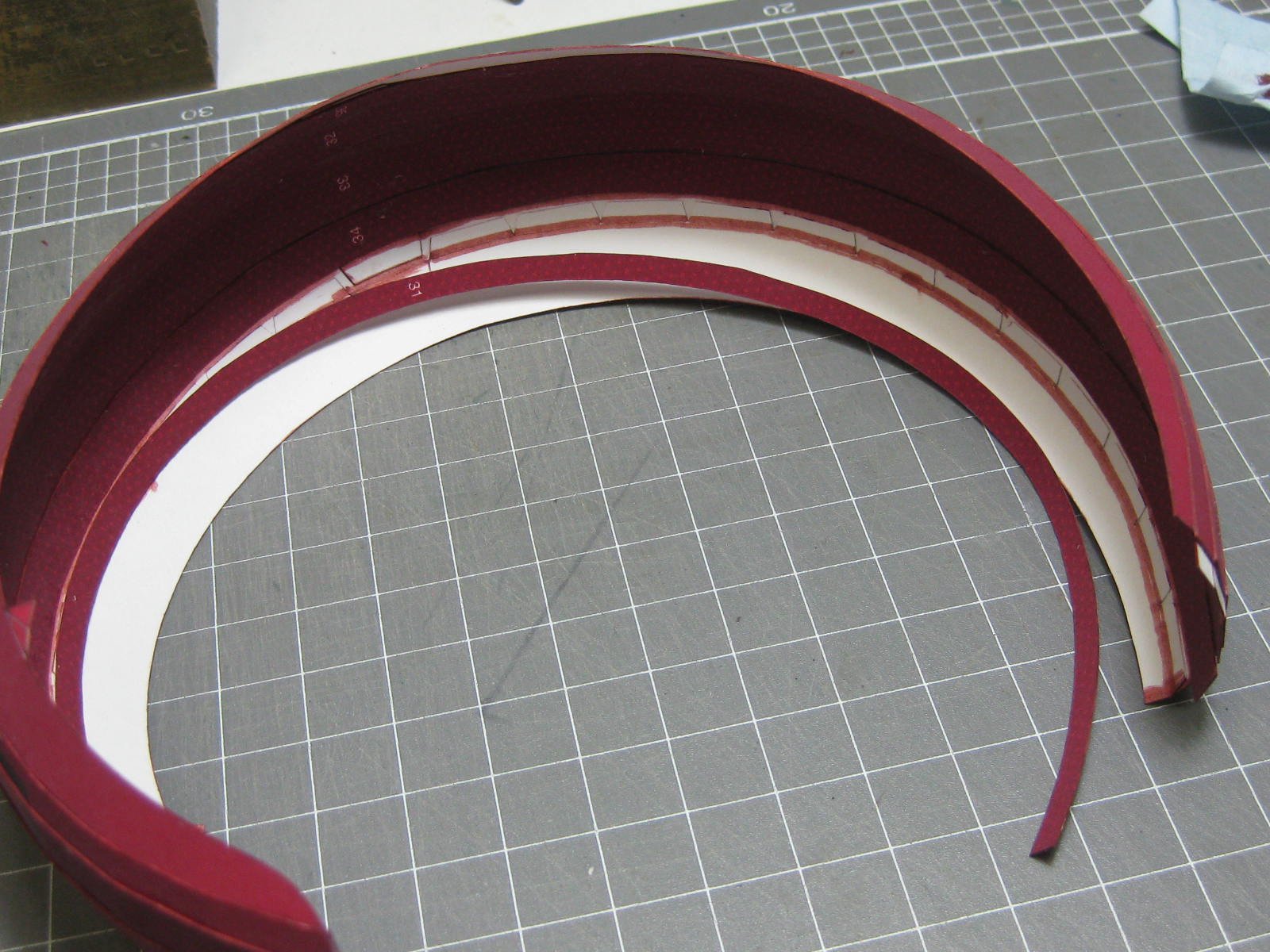
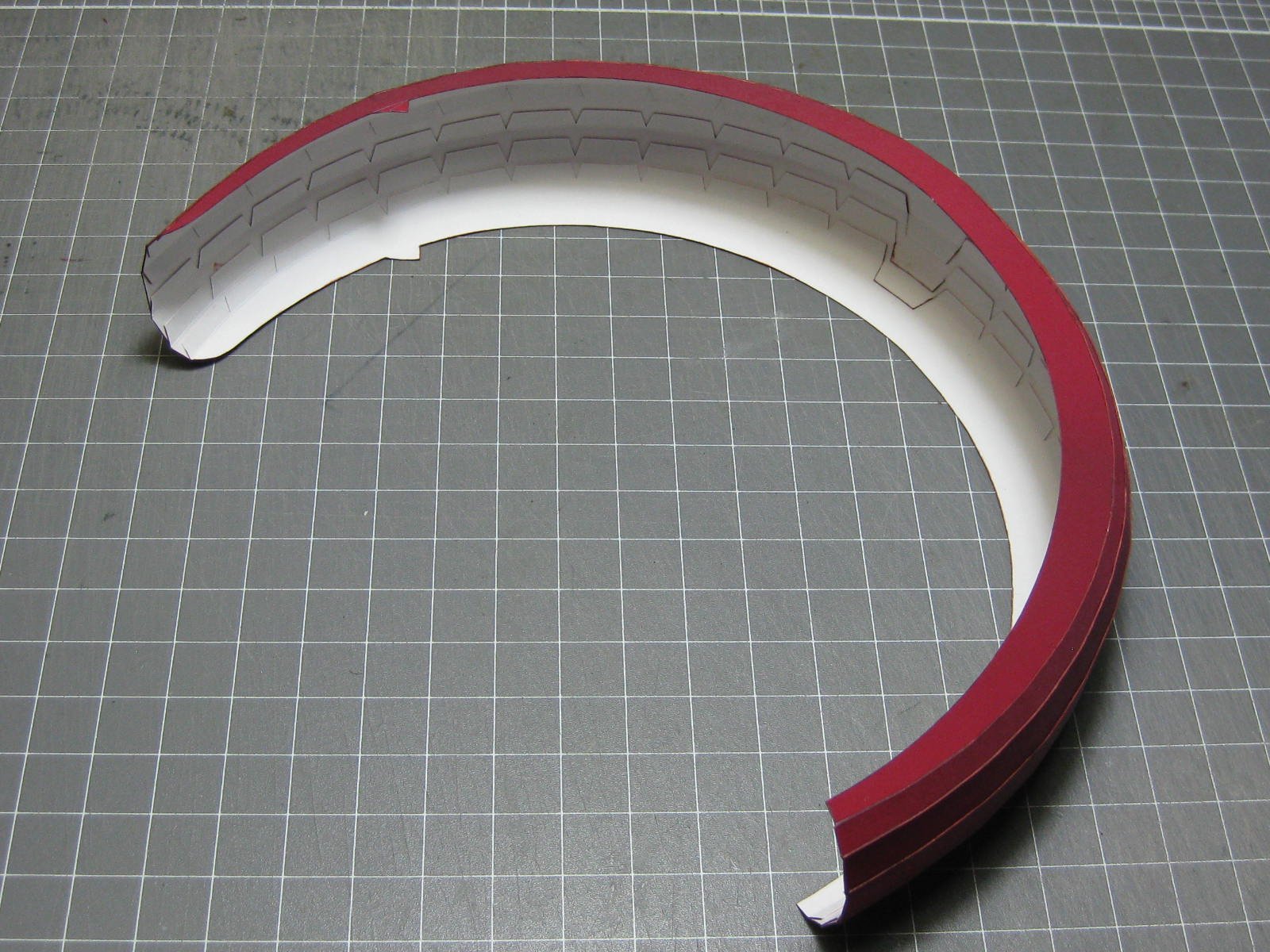
The front mudguard. LOTS of tabs
") :
:
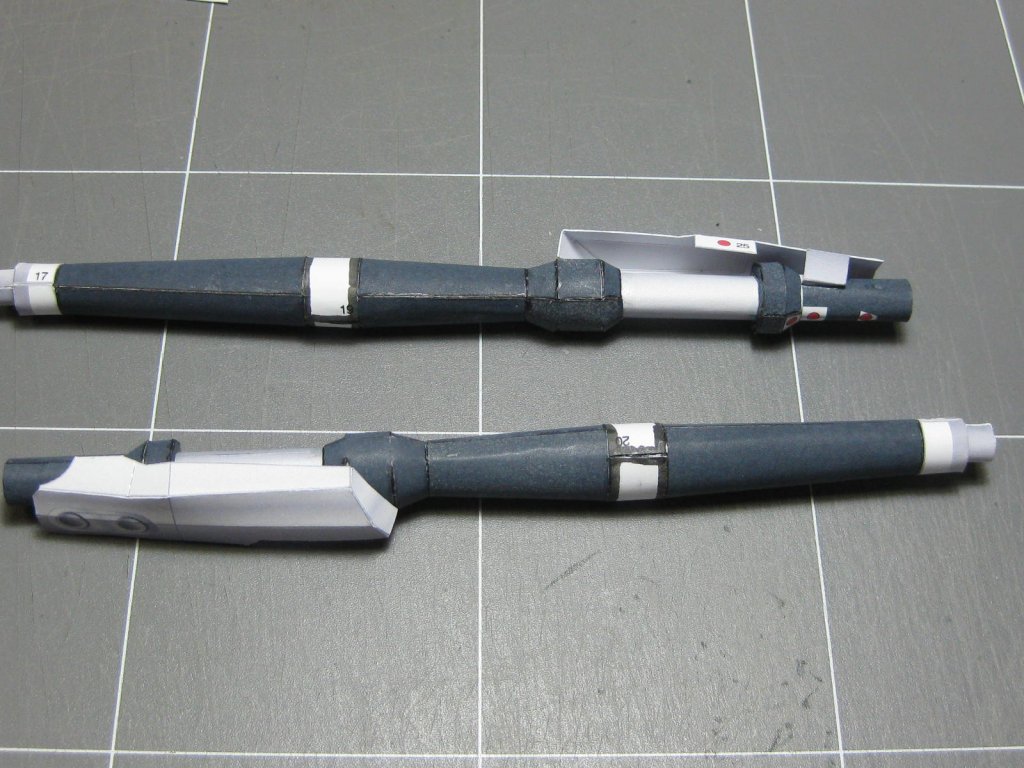
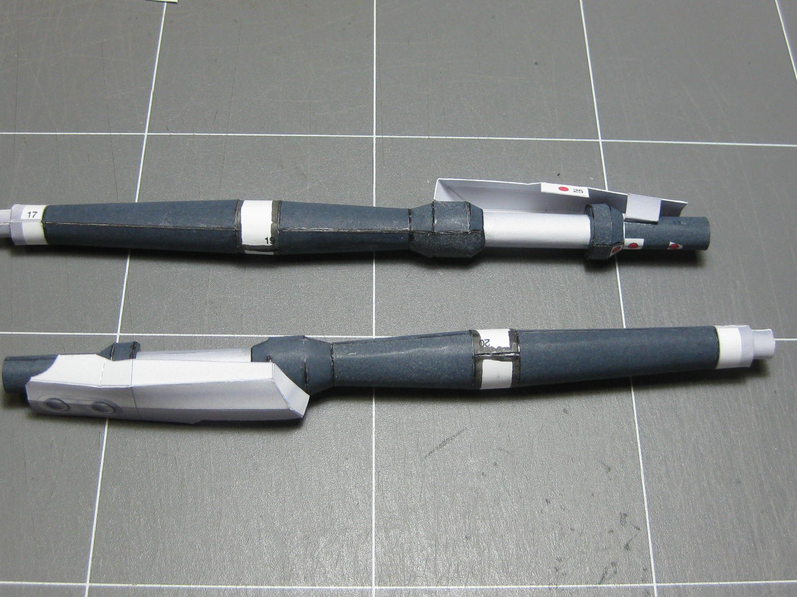
The front forks. There is a paper tube running the full length, they're quite strong :
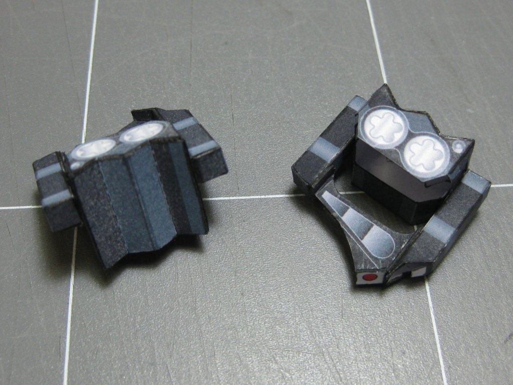
The front disc brake calipers :
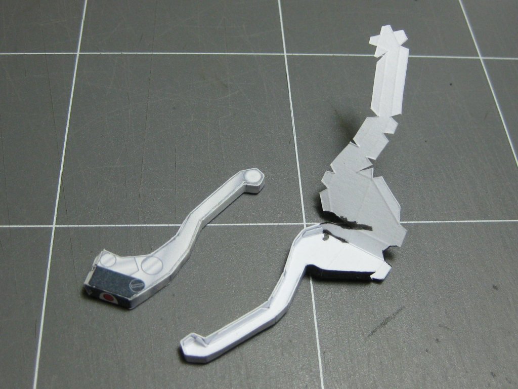
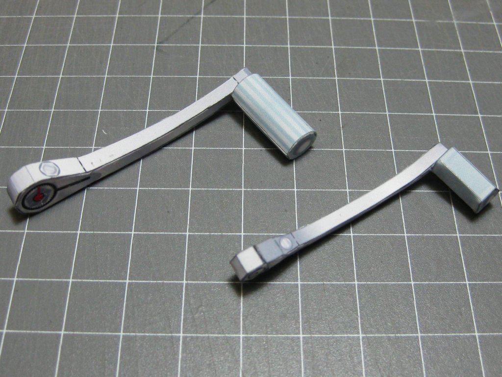
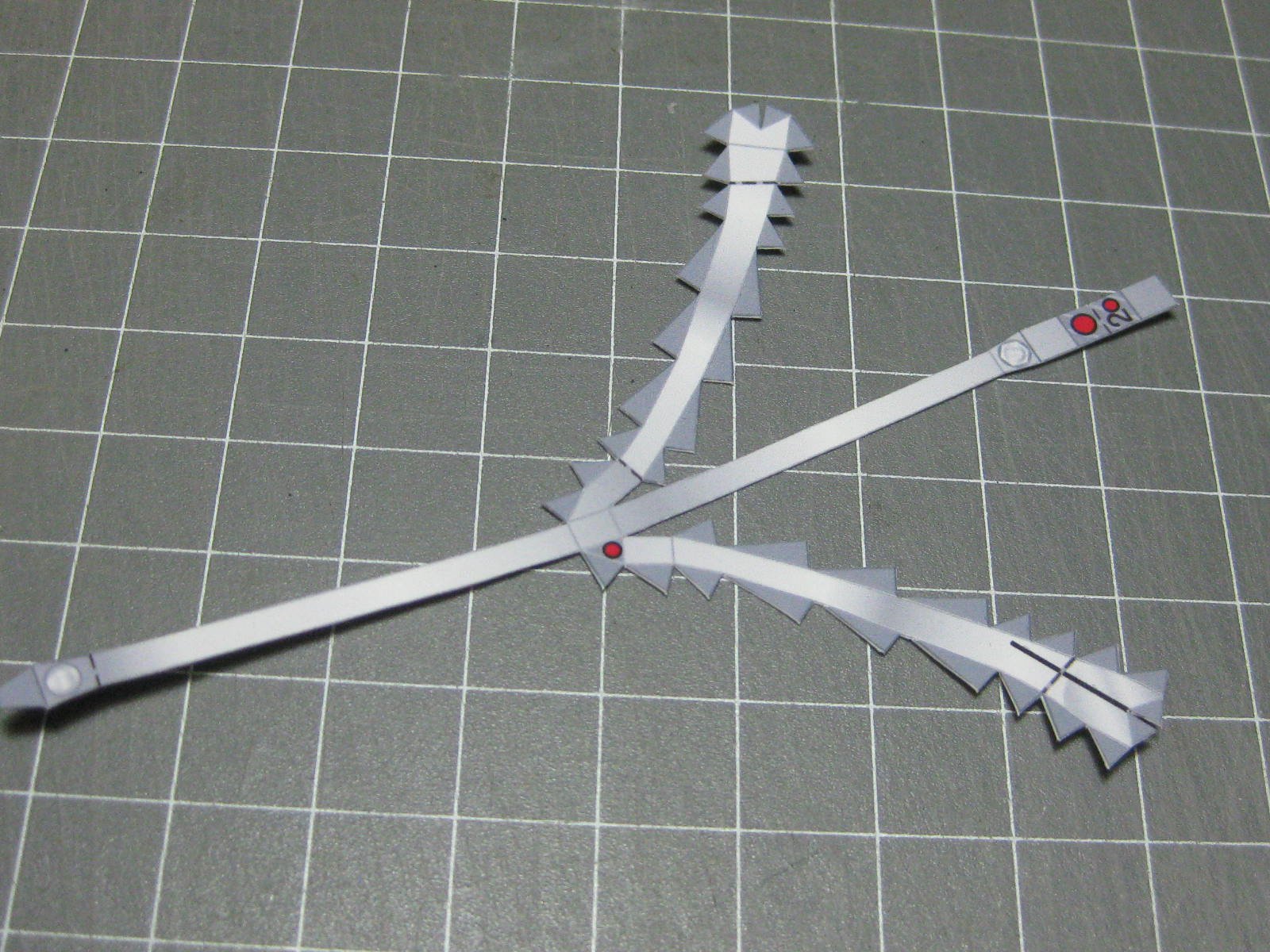
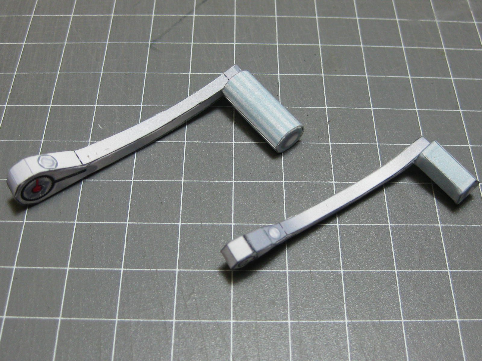
The brake and clutch levers. These were a bit difficult to make, but they turned out very nicely :
Danny
-
Lots more done. Here is the partially completed frame :
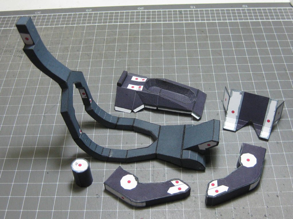
And more frame pieces :

The start of the rear suspension :
Danny
-
1 hour ago, amateur said:
I don't understand the designer: he should have been aware of paper thickness
Better kits, like Halinski, DO take the paper thickness into consideration
") .
.
Danny
- Canute, popeye the sailor, Piet and 1 other
-
 4
4
-
5 hours ago, amateur said:
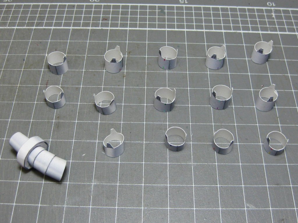
tomorrows funpart: roll to make a column of max 2 milimietre wide at the top, and three and a half at the lower end.
fun: the cardbord is almost .3 milimeters thick.
Note the icon next to the part. This means you roll the piece as tightly as possible, starting from "zero" to the required diameter. This would be almost impossible with anything thicker than 0.25mm paper. You may need to re-print the part on thinner paper.
Rolling a piece from a "zero" diameter is also nearly impossible, but the method I found works really well for any parts that are 8-10mm longer or less (see below). I ground the end of the eye off a large needle, leaving a kind of 2-pronged fork. The needle is fitted into a thin-type Xacto knife holder. The paper is inserted into the eye, with about 1.5mm hanging out. Next begin by rolling the holder for two turns until it holds the paper tightly. Apply a thin bead of PVA for 20-30mm to the paper and continue rolling. Apply PVA to the rest of the paper and roll until the piece is done. Remove the part and gently squeeze it round if needed (it will be more oval shaped at first).
It takes a bit of practise
but I can make a rolled cylinder in about 1 minute, depending on the finished diameter.
Note : longer pieces can be done using this method, but it's more difficult. Find the needle with the longest eye you can get to make the tool. My needle has a finished eye (after grinding) of only 3mm, but there are no doubt larger needles out there.
To get a better idea of what I'm talking about click THIS LINK to see the post in my HMS Hood build where I show how I do it.
Danny
- popeye the sailor, Piet and mtaylor
-
3
-
9 hours ago, Richmond said:
Having read the construction manual they suggest scoring all the printed edges of the planks with a razor blade
Rather than a razor blade I use a blunted #11 Xacto blade in a holder, which doesn't actually cut into the paper. This method rarely requires extra painting.
Danny
-
7 hours ago, Richmond said:
There is a YouTube video of them here
Hmmm .... one thing missing in that video - a large pack of Band-aids 😳. Brave (or stupid) guy using a double edged razor blade to cut the blocks off the tree
 .
.
It looks like an easy way to assemble them though. Glue drying too fast may be a problem, especially in Darwin's heat. I'd be using PVA.
Danny
- mtaylor, Canute and Old Collingwood
-
3
-
Another follower here
. I'd either be buying the laser-cut blocks or go with timber blocks - those ones supplied look like an exercise in frustration, cutting and laminating them would take an age . When assembling them make up a little jig (one for each size) to hold the pieces in position while you glue them up.
Danny
- druxey, mtaylor, Old Collingwood and 3 others
-
6
-
Pretty good job for the 1st planking and it will make a good foundation, but have a big think about the 2nd planking before you start anything. You won't want to follow the run of the planks for that - i.e. NO sharp pointed panks.
Danny
- SIDEWAYS SAM and robdurant
-
2
-
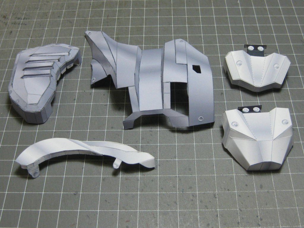
Thanks Richmond
.
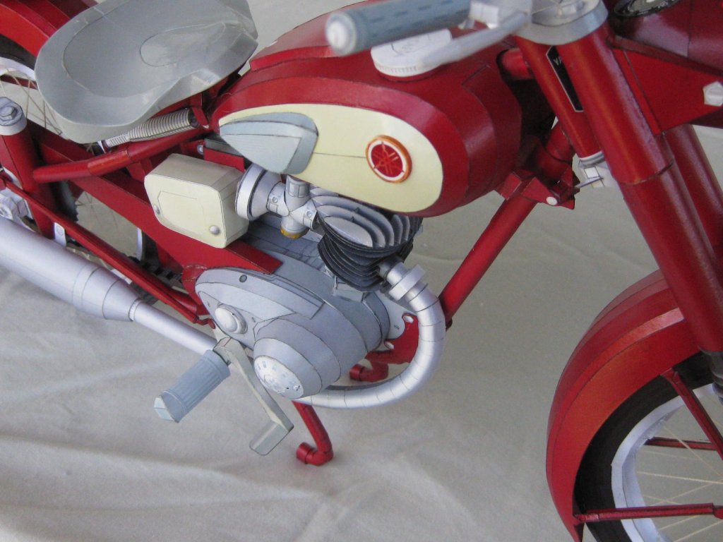
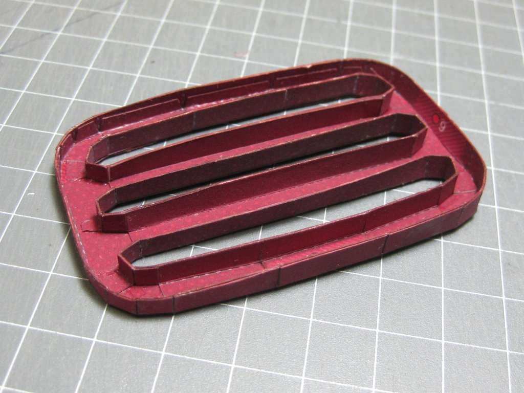
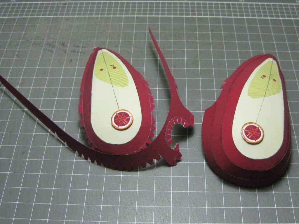
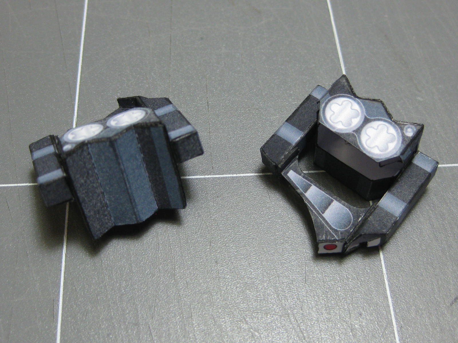
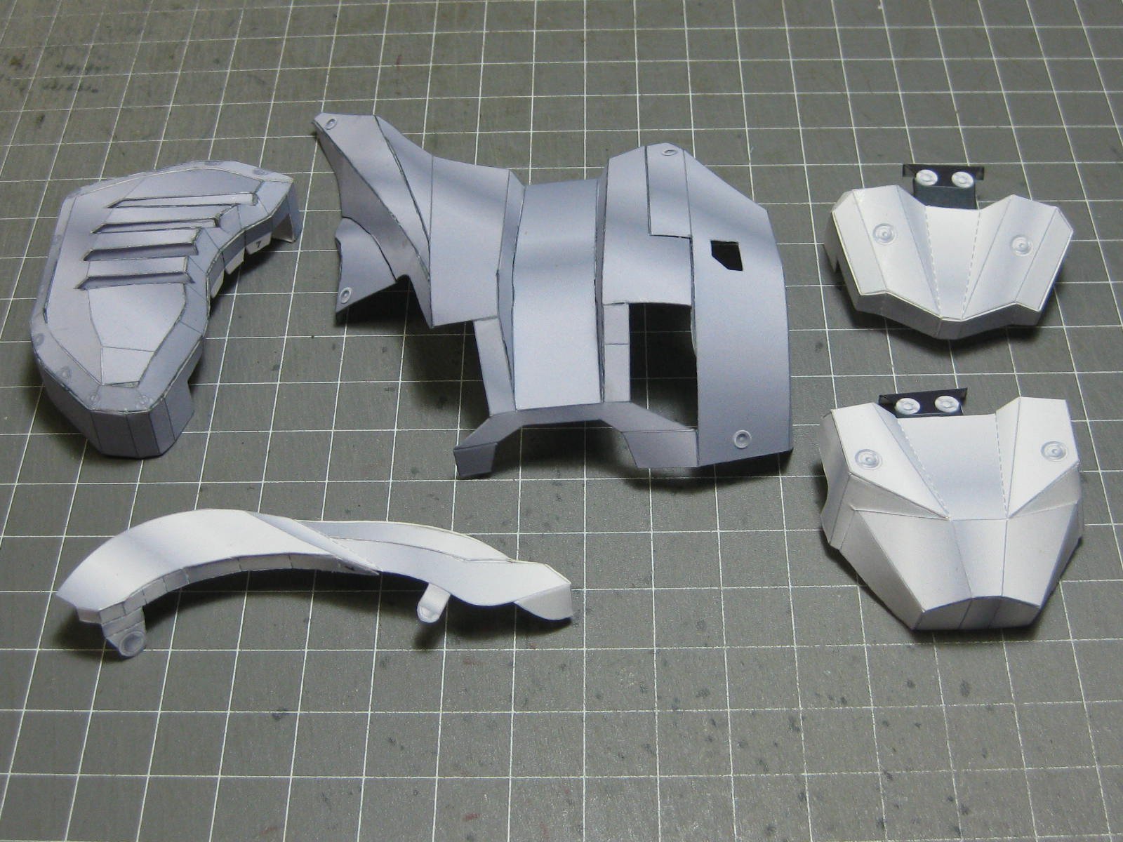
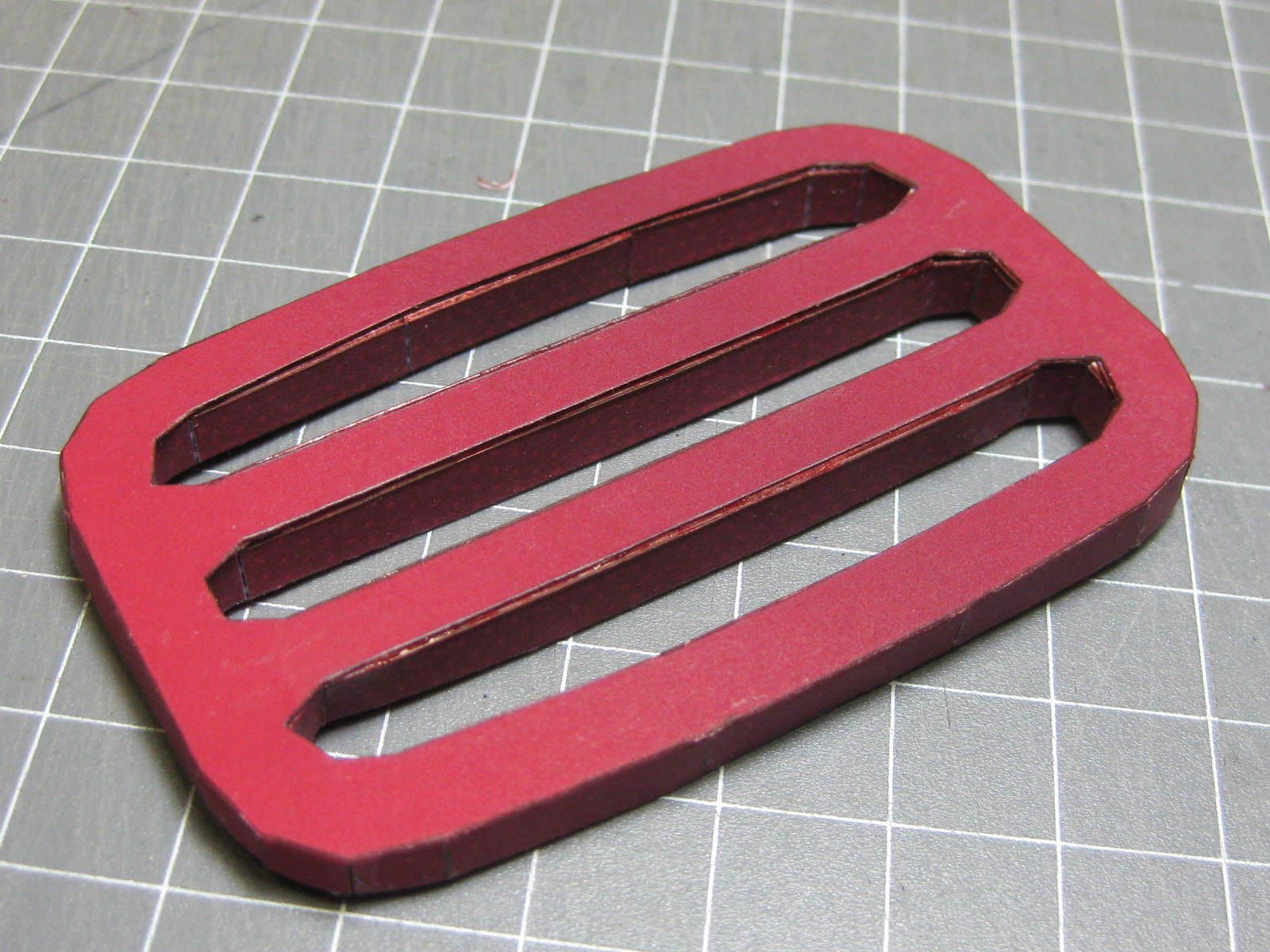
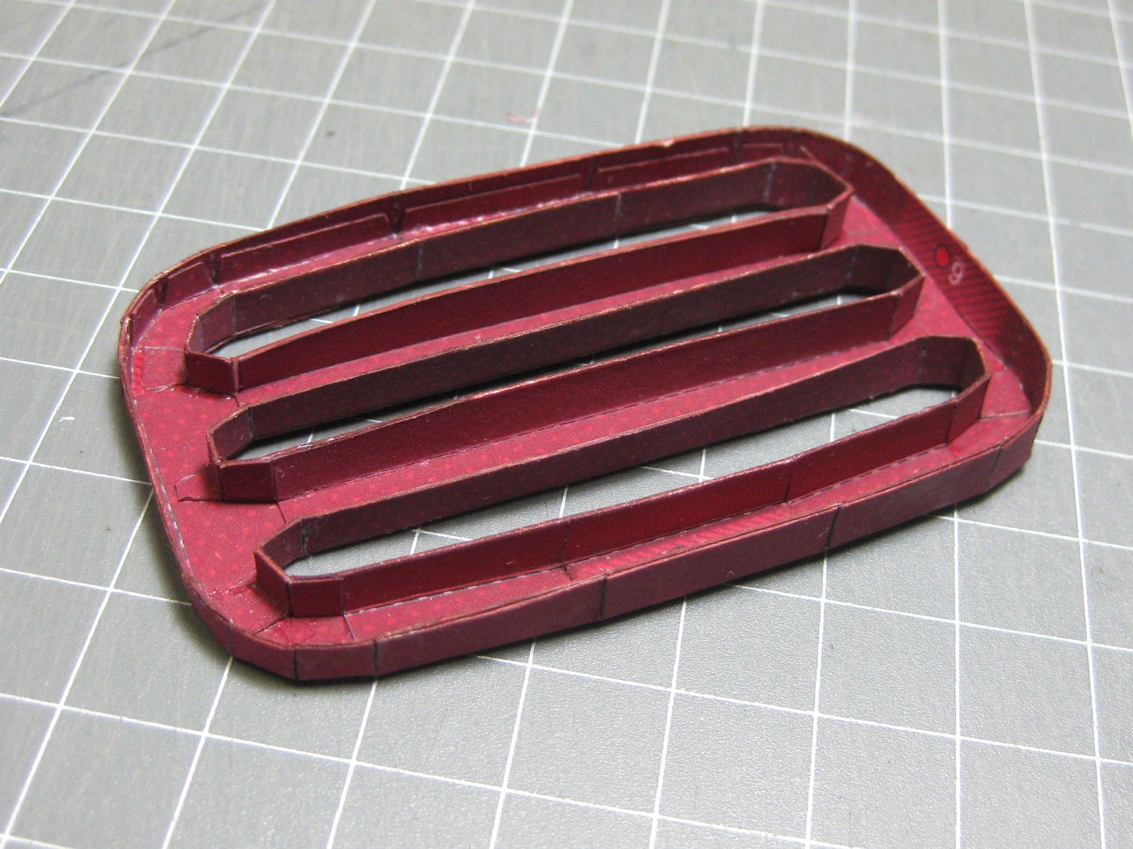
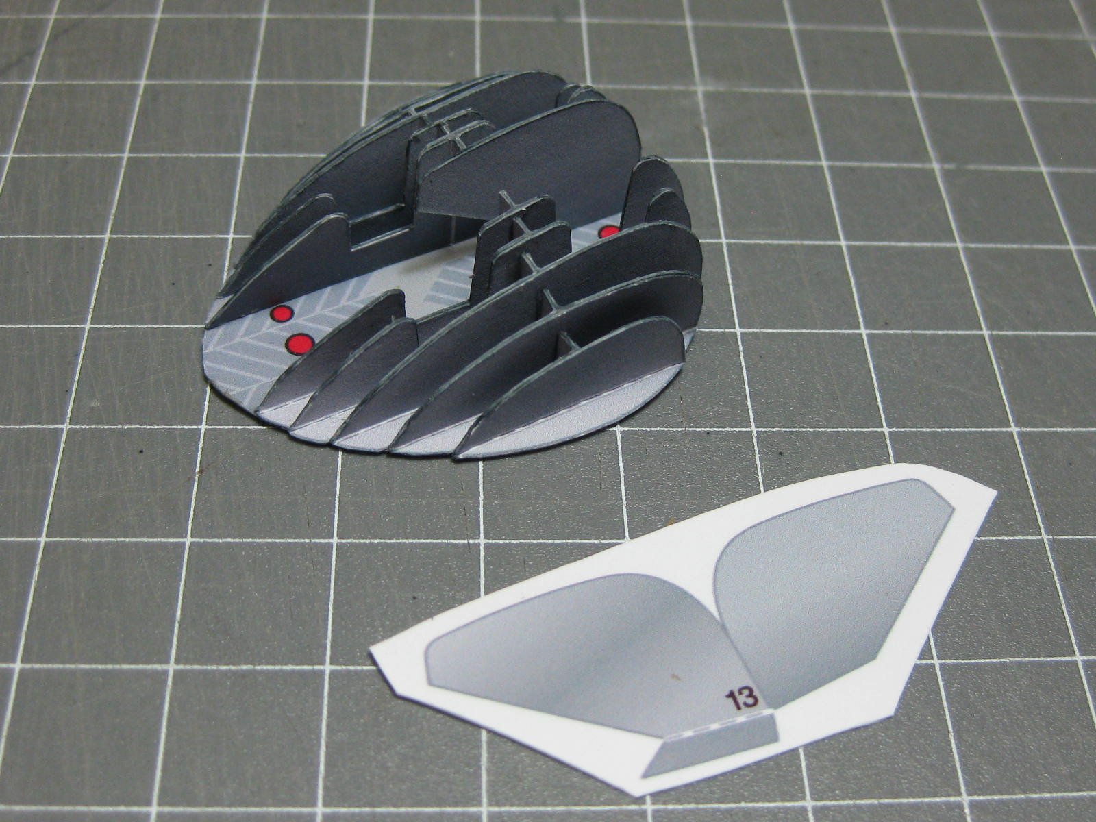
I've made up all the side covers. The louvred one (top left) was particularly tricky to make :
Danny
- CaptainSteve, mtaylor, druxey and 7 others
-
10
-
-
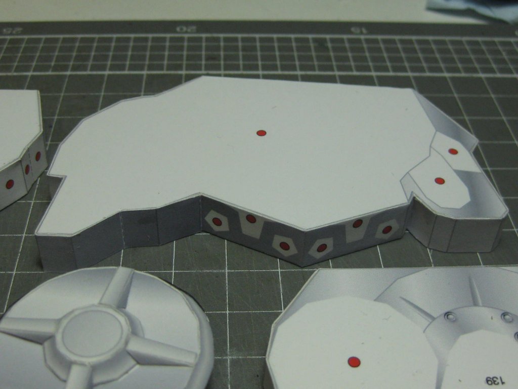
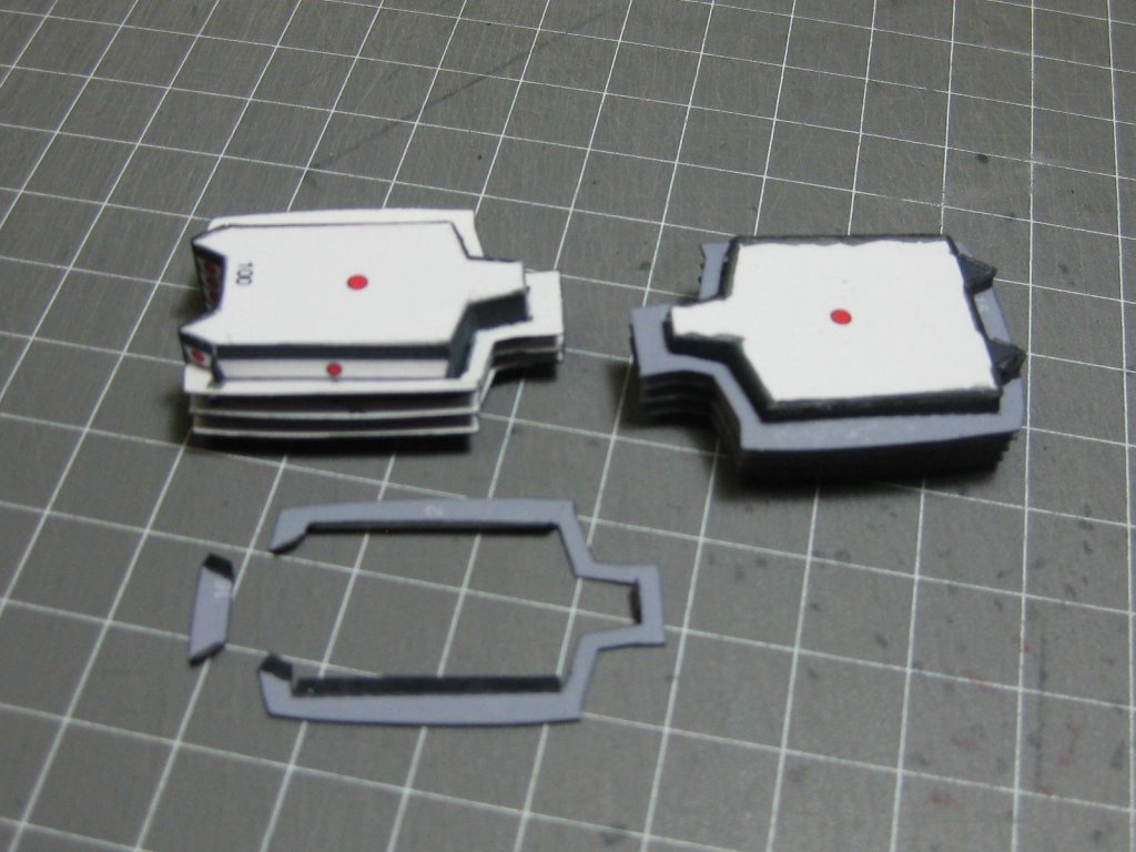
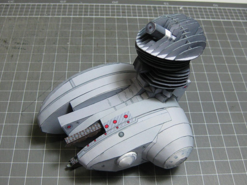
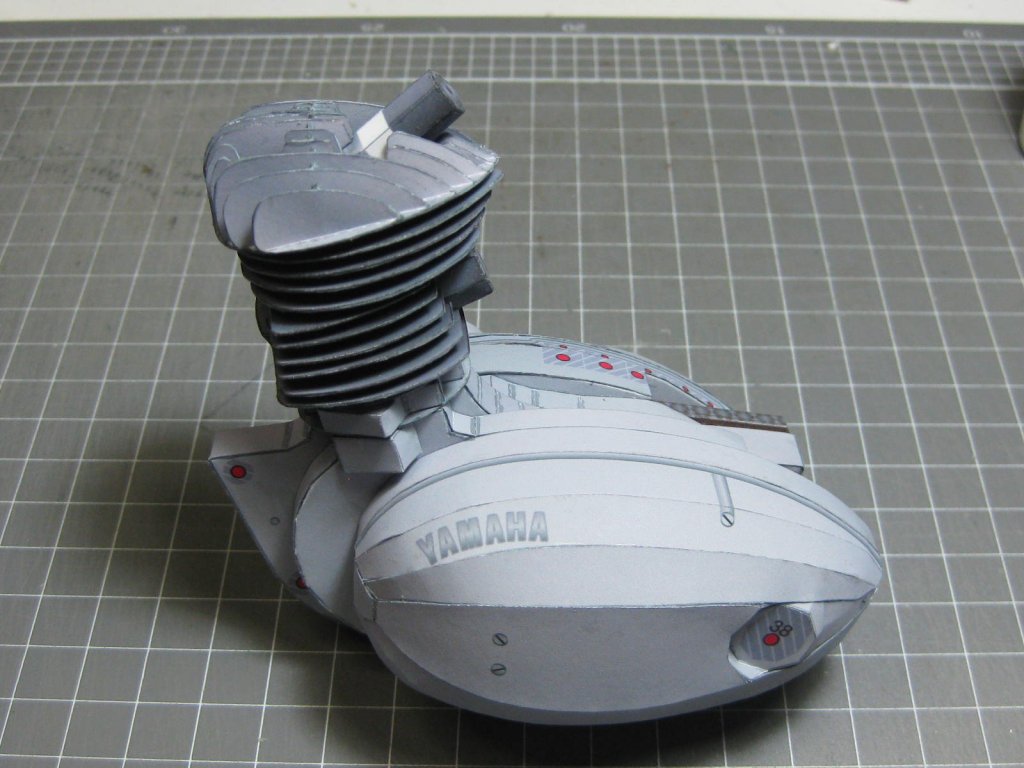
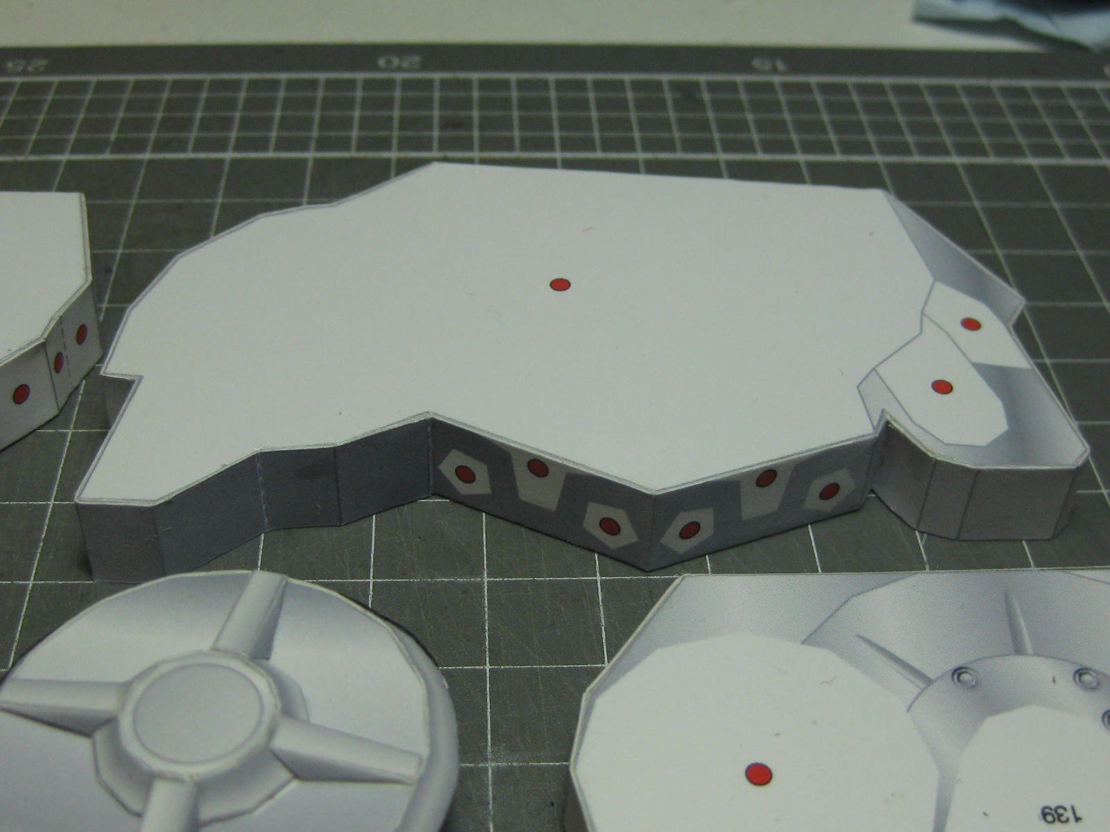
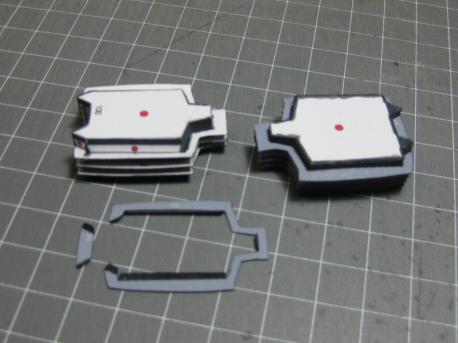
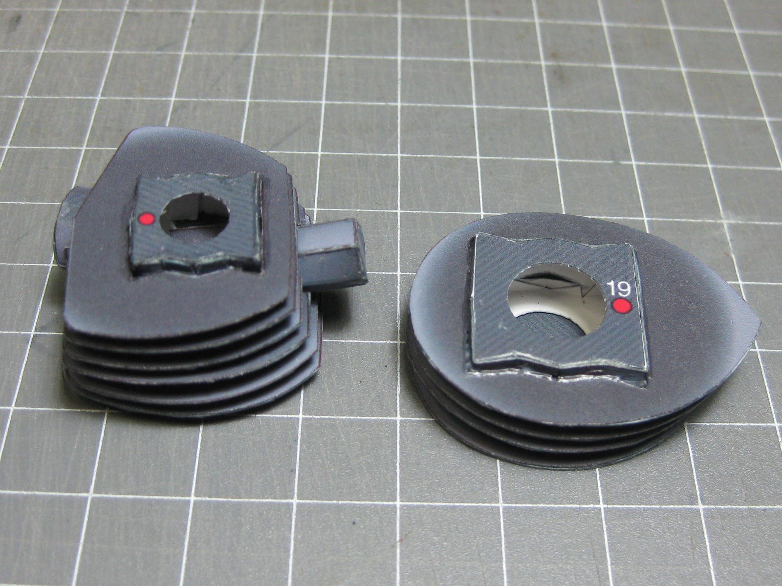
Here are most of the pieces of the crankcase. All of them have been folded and glued ready to assemble :
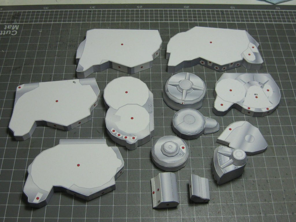
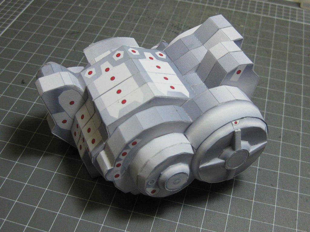
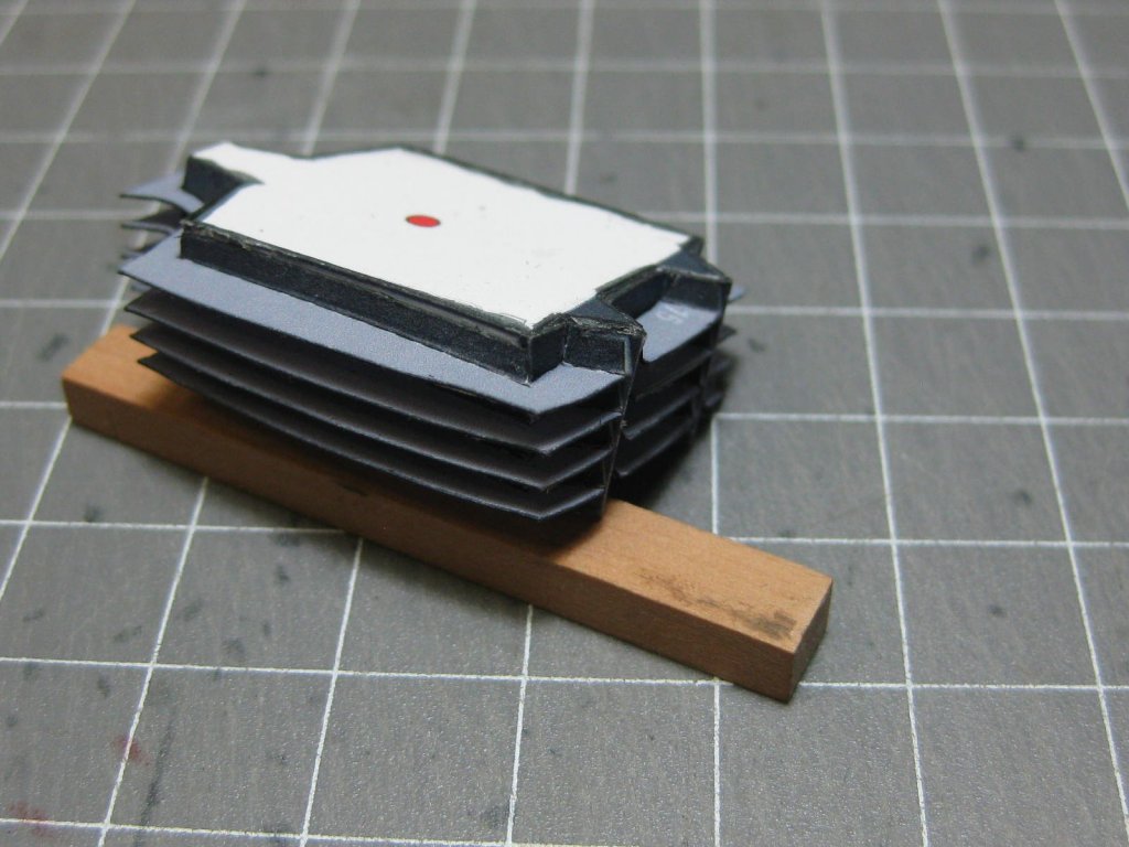
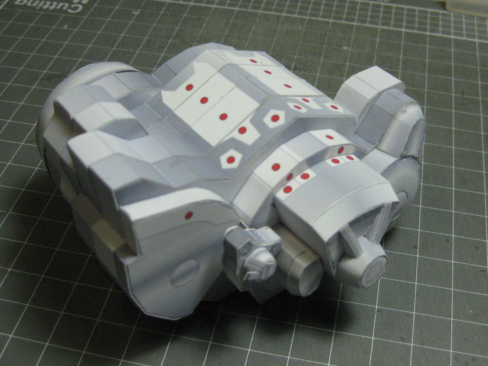
The crankcase assembled :

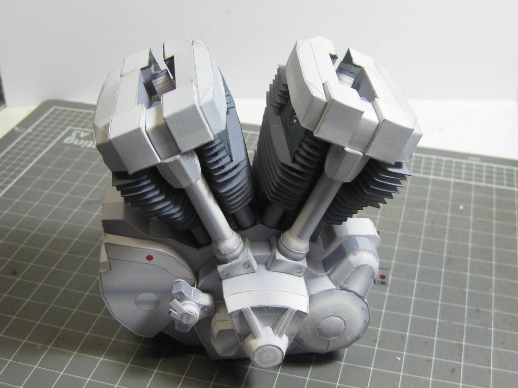
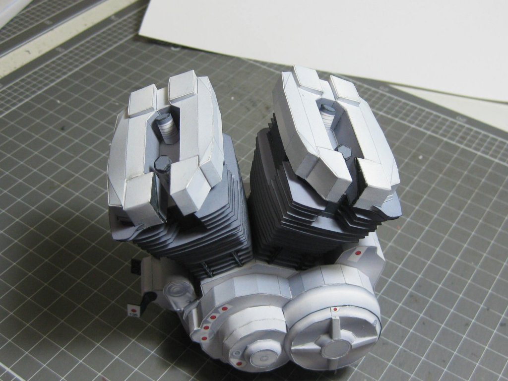
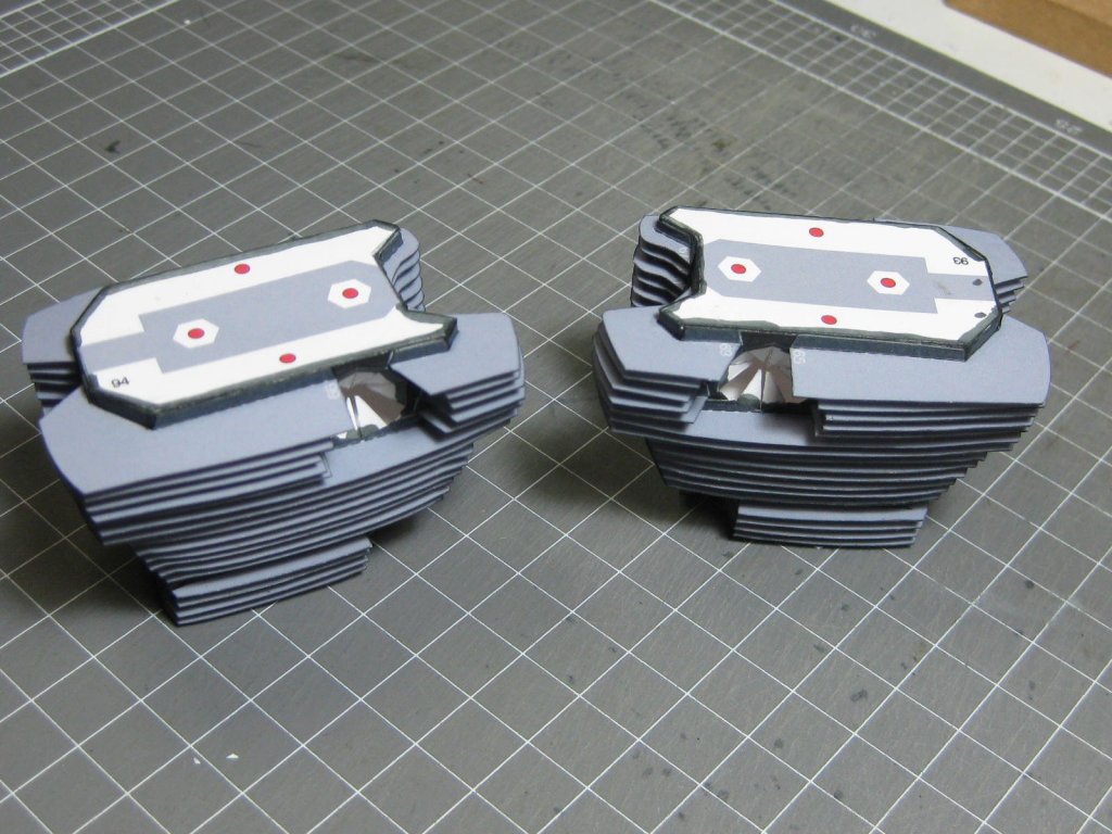
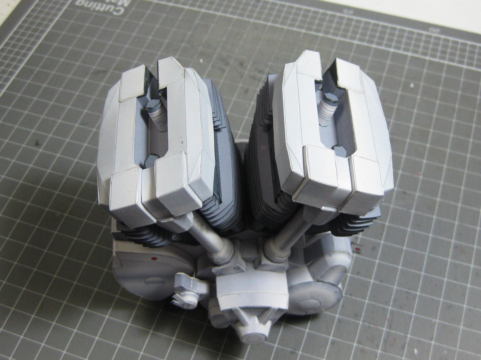
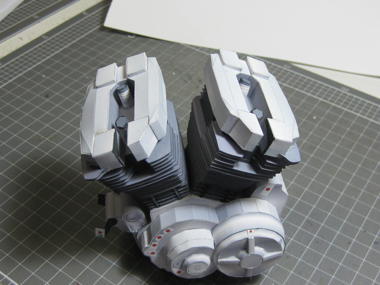
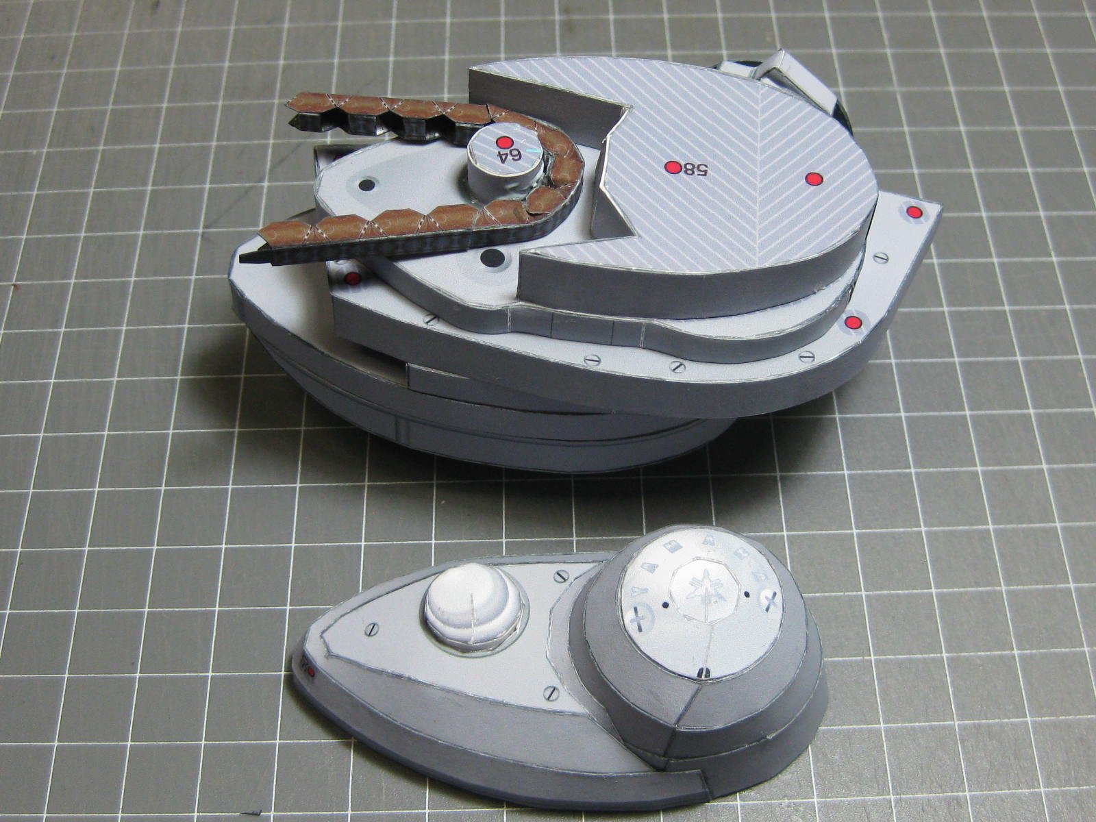
The barrels and other accessories fitted to the crankcase. That concludes the engine, I'll put it aside for now :

Danny
- GrandpaPhil, druxey, CaptainSteve and 8 others
-
11
-
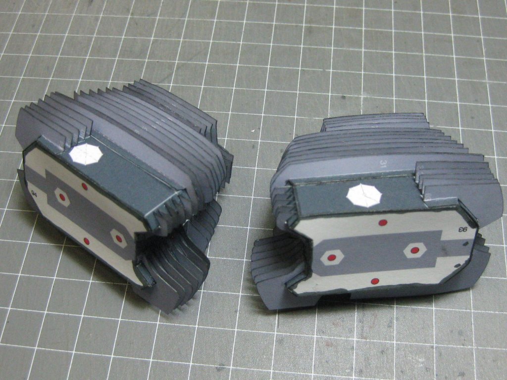
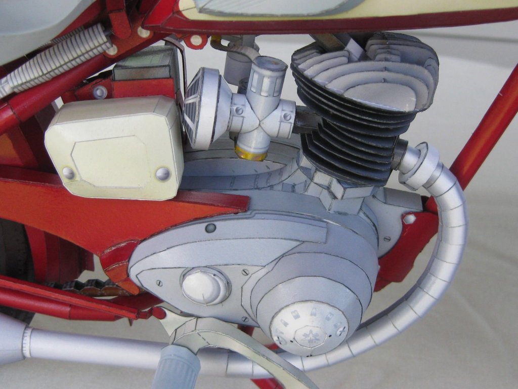
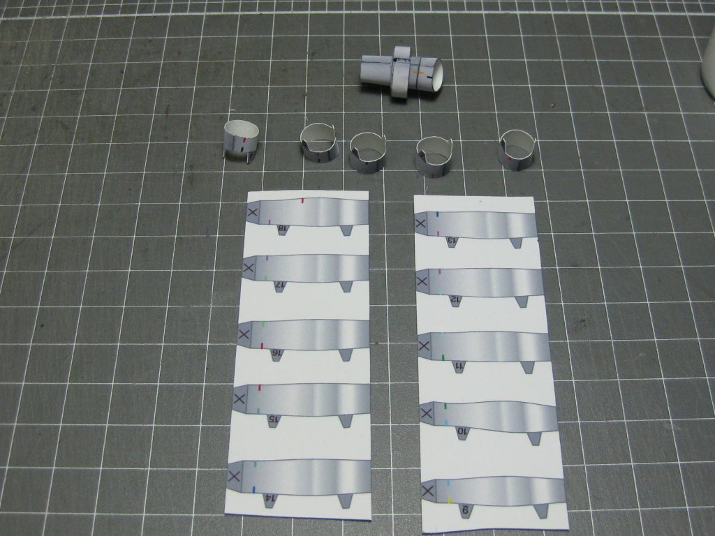
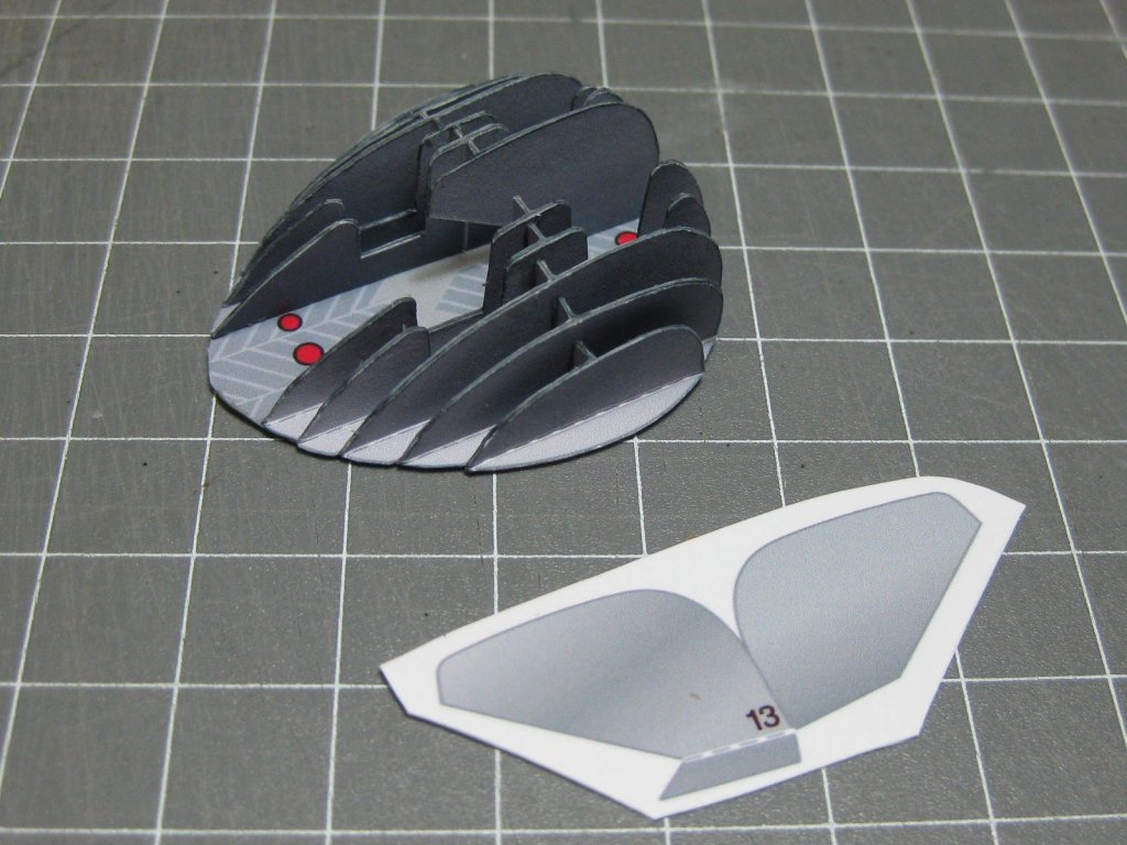
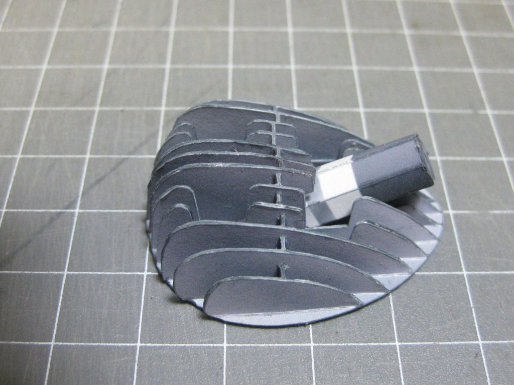
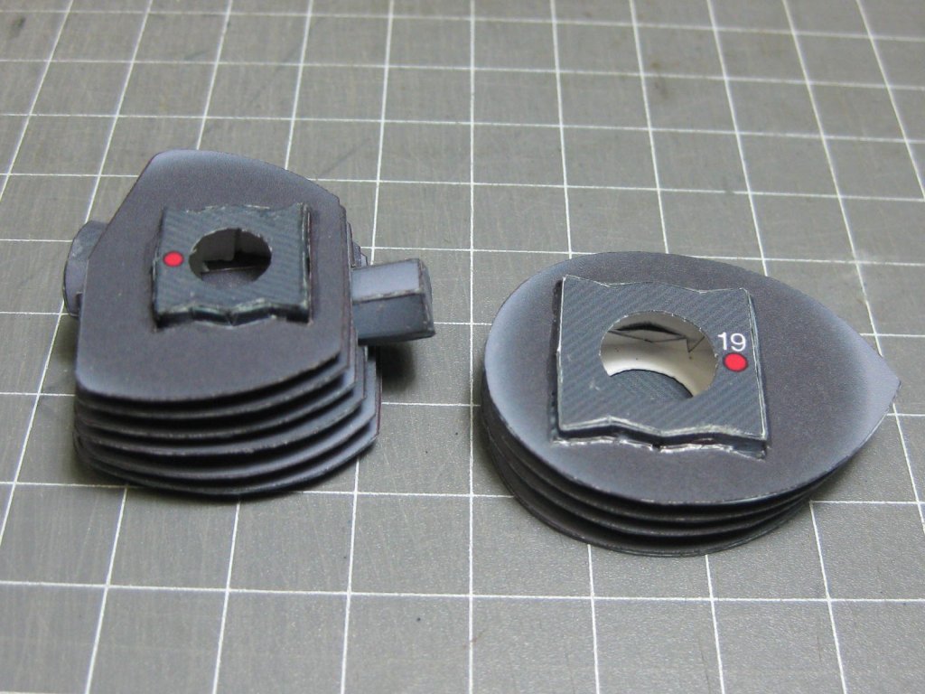
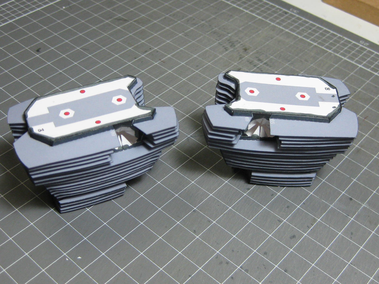
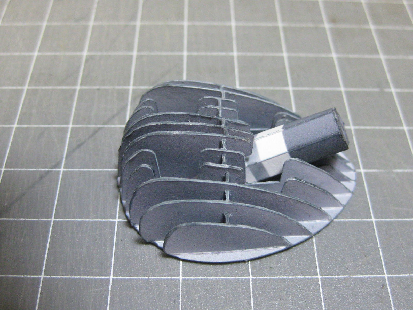
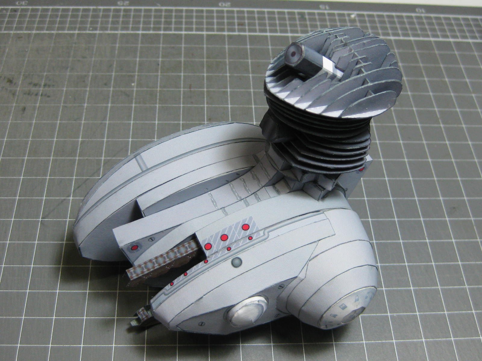
There are three sections in each of the two barrels, and 17 rows of fins in each barrel. Cutting,folding and gluing the fins took the best part of two days :
Danny
-
1 hour ago, EdT said:
Also, I'd like to put in a vote for not quoting entire posts - takes up space and makes it harder to follow a conversation.
Fixed
. A tip for those who don't know - don't simply hit the "Quote" button when replying as it copies the ENTIRE post to the reply. If you want SOME of the original post in your reply - highlight the appropriate passage (Shift + Left or Right Arrow or drag with your Mouse) and click the little "Quote Selection" button that appears. BTW - you can Edit your OWN posts if needed.
Back to you Ed
, Danny
- Jack12477, rwiederrich, PeteB and 3 others
-
6
-
Thanks guys. Denis, I doubt you did much wrong on yours, it looks great in the pic
.
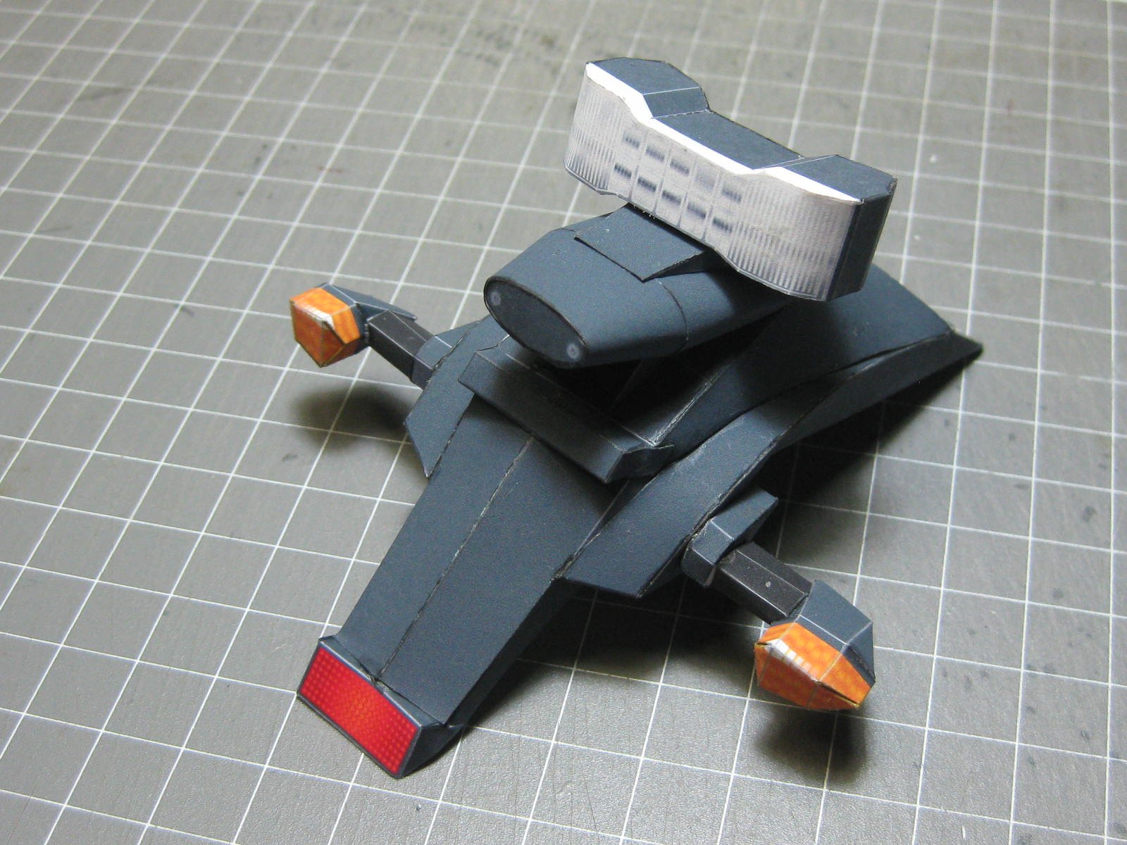
I've made the tail-light/rear mudguard assembly :

Now to start the motor. This has 13 pages of parts, so it may take a while.
Danny
- popeye the sailor, gjdale, druxey and 5 others
-
8
-
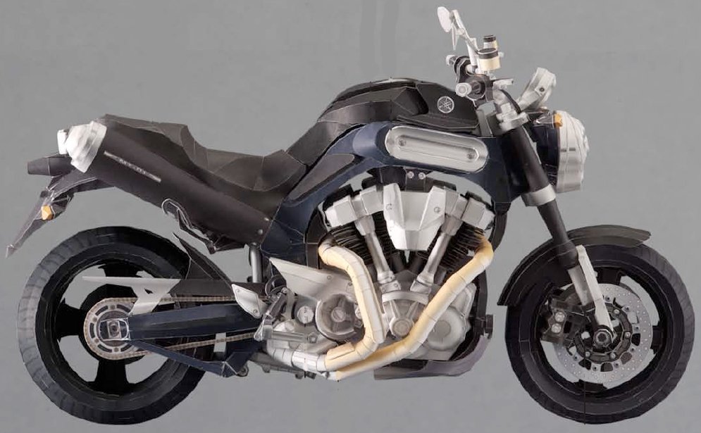
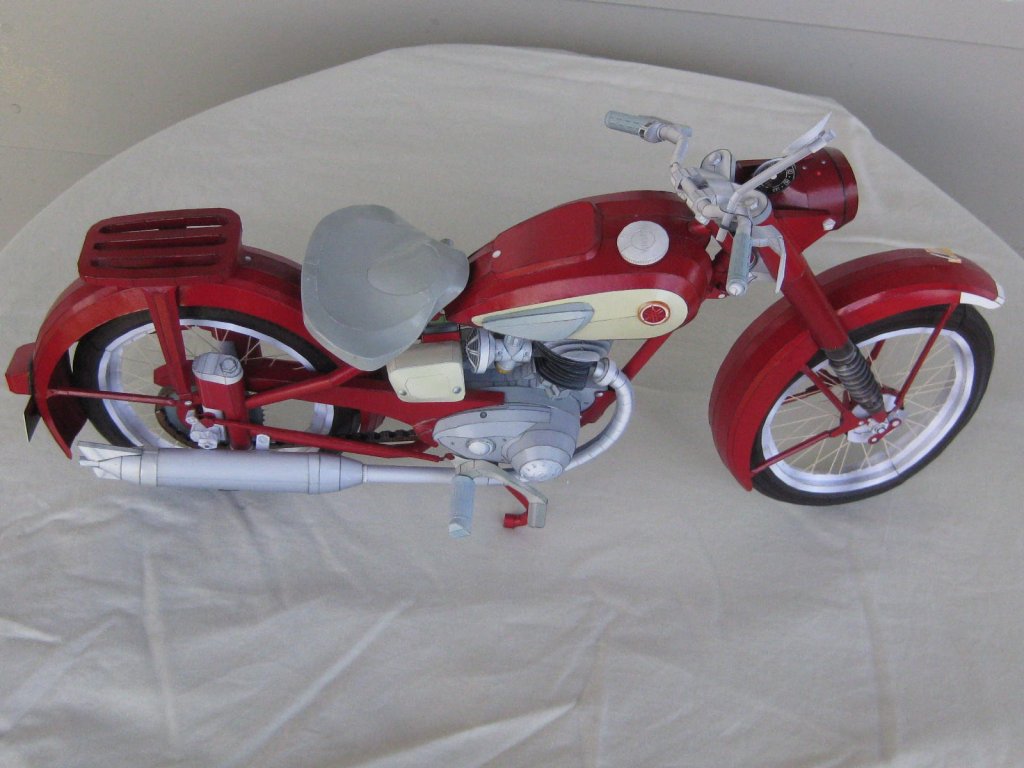
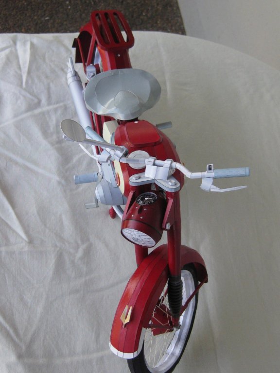
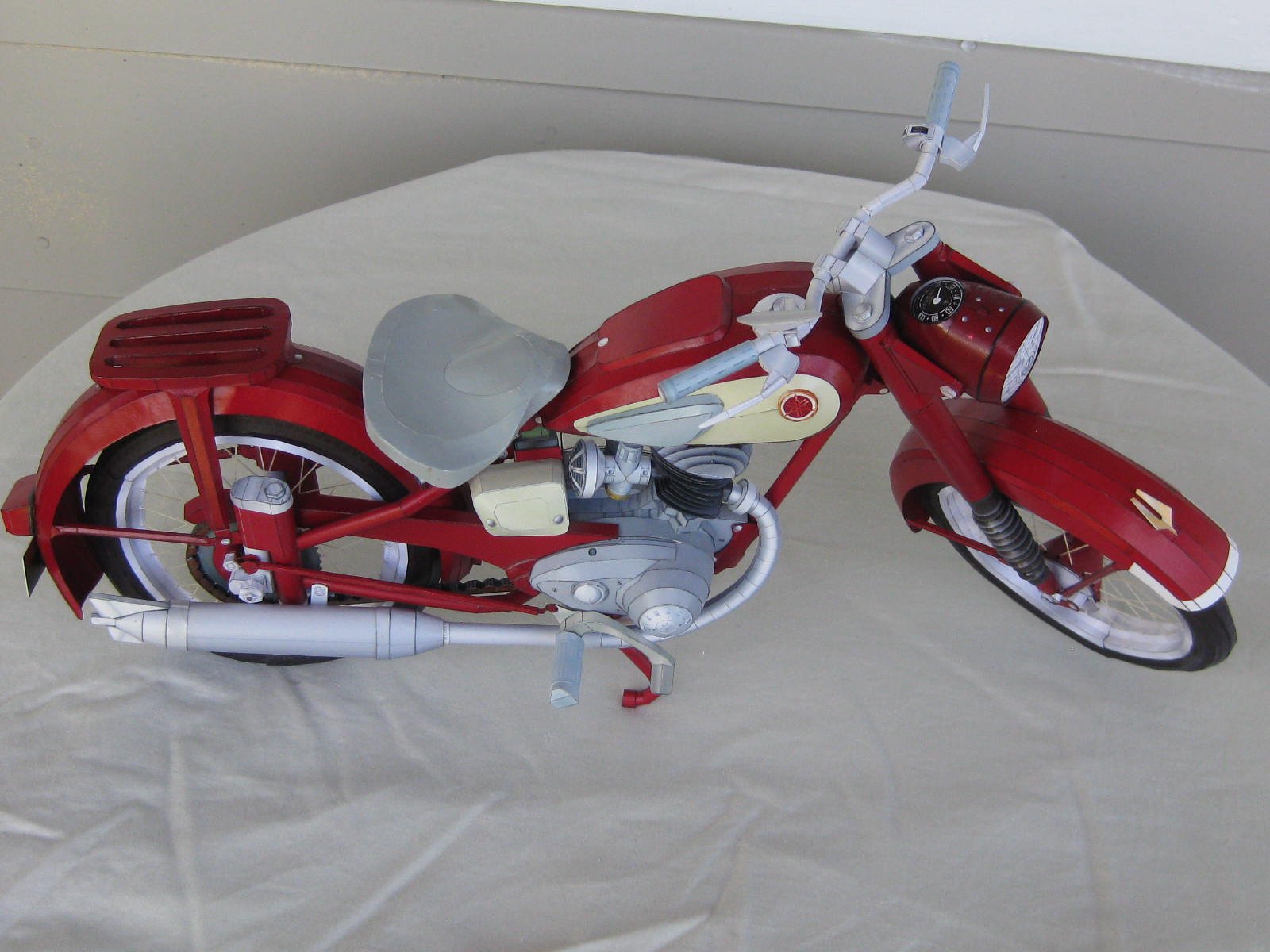
Hi all, this is the start of my latest Card model- a Yamaha MT-01, which was built between 2005 and 2012. As I did with the other Yamaha (YA-01) I built this will be a very truncated Build Log, consisting of pics of the major stages. Here's a pic of how it will look (hopefully
) :
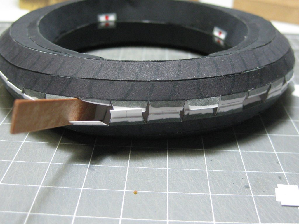
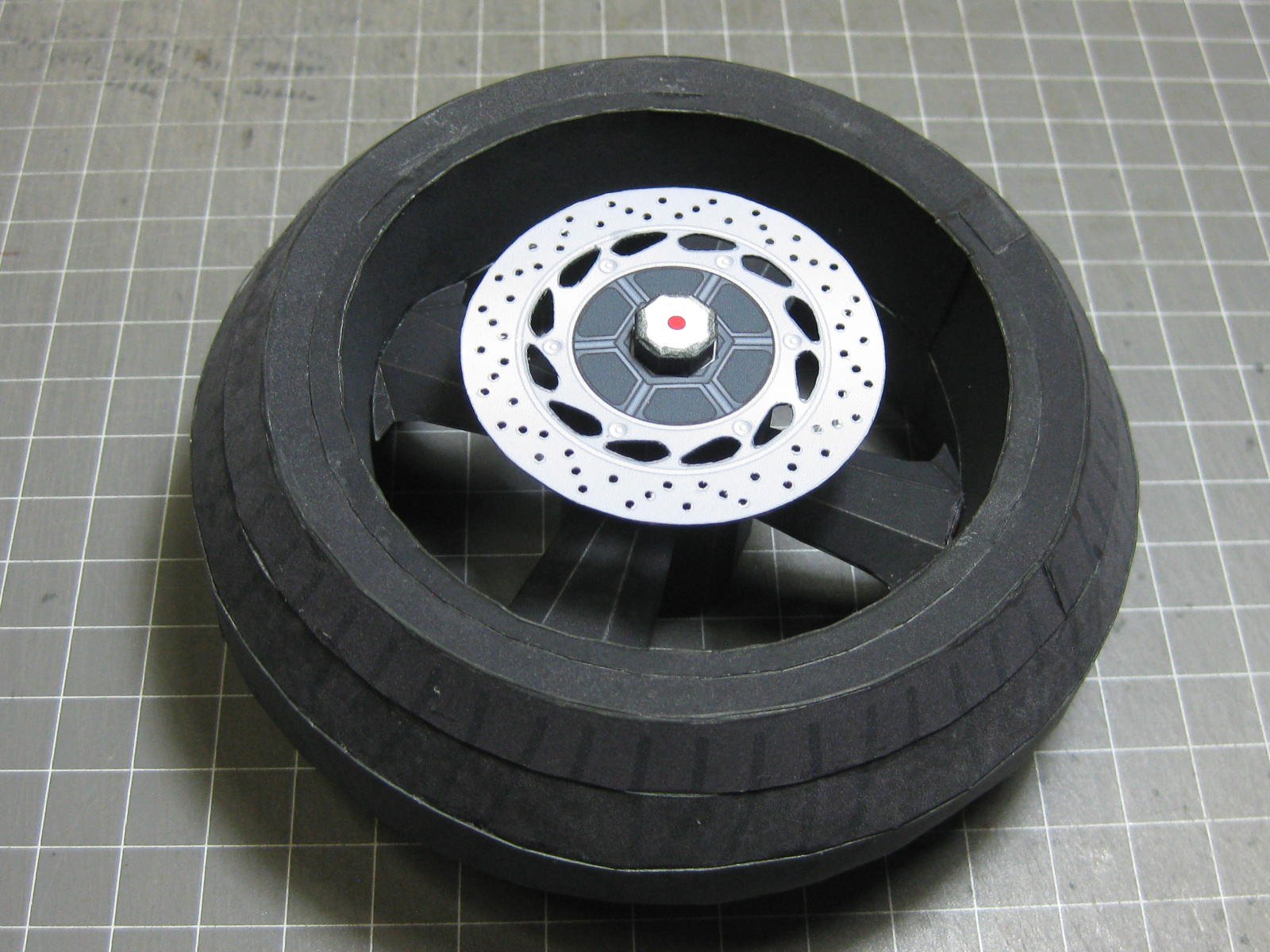
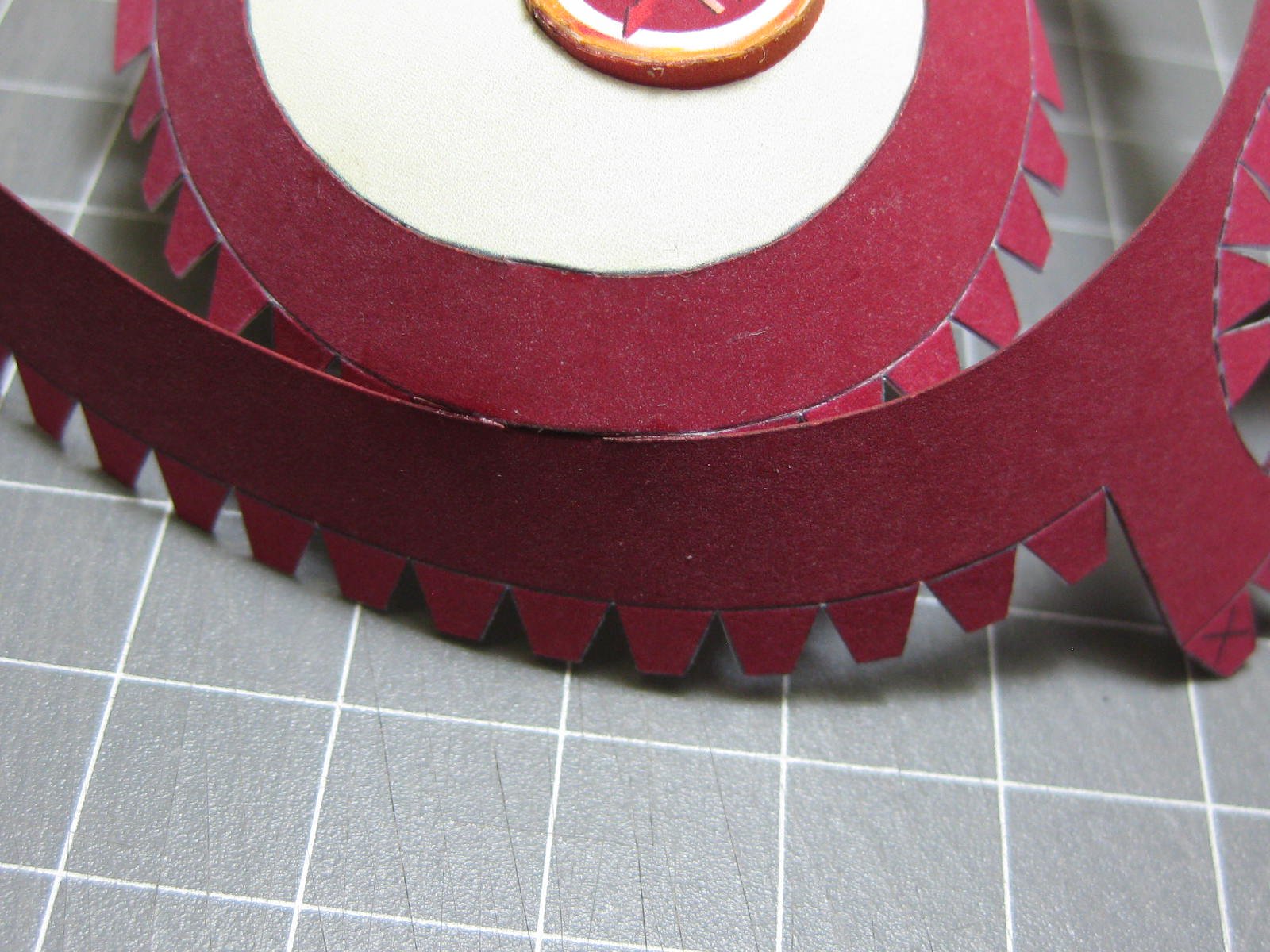
I started this one by building the wheels to see if I would carry on with the build. If you saw my YA-01 the wheels were the hardest parts to build, and didn't turn out 100% on that one. This time they turned out a LOT better, not perfect due to the tags, but still good enough to keep going
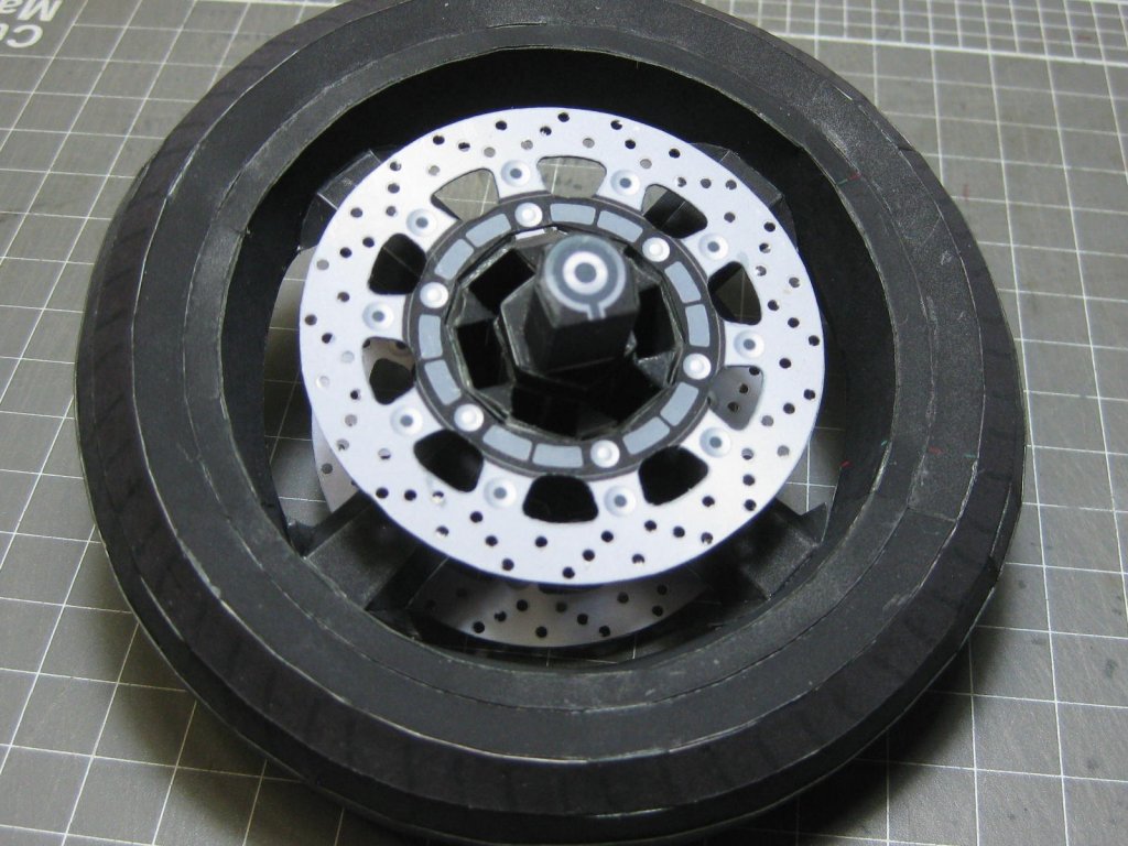
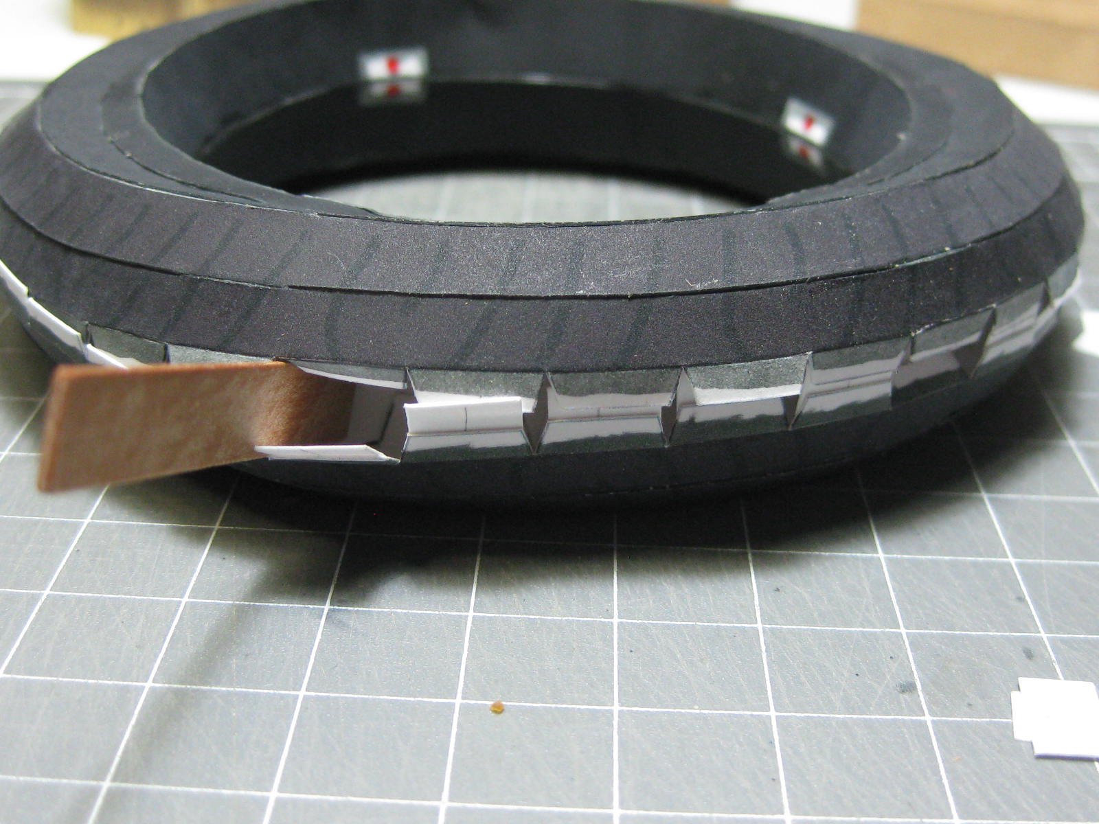
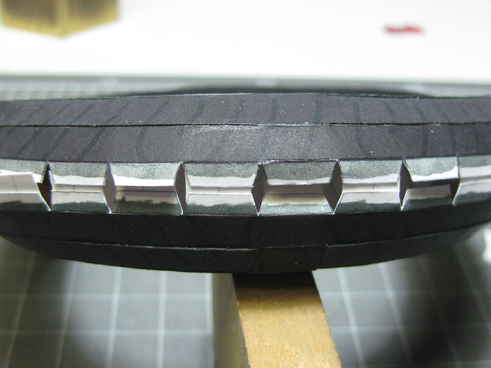
. The design, being mag wheels, was different to the spoked wheels of the YA-01. Here are some pics of the wheels :

My method of fitting the last part - a band in the middle of the tyre. I glued extra card between the tags to get them the correct distance apart and stabilise the whole unit, which had significant distortion and stress before I added them :

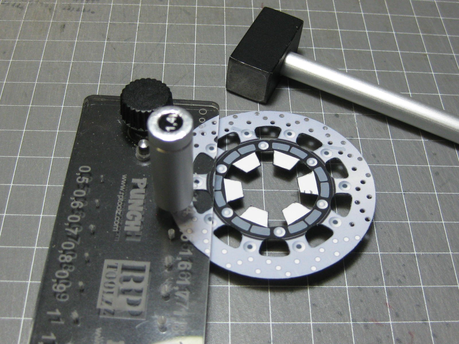
Punching out the cooling holes in the twin disc rotors :

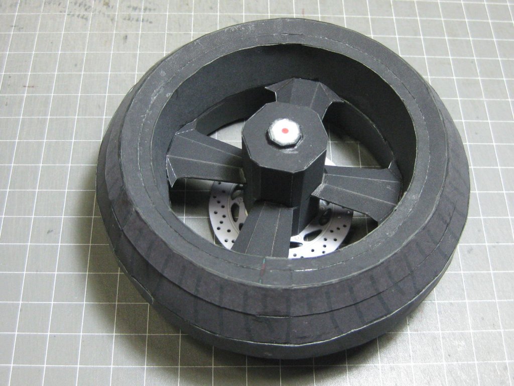
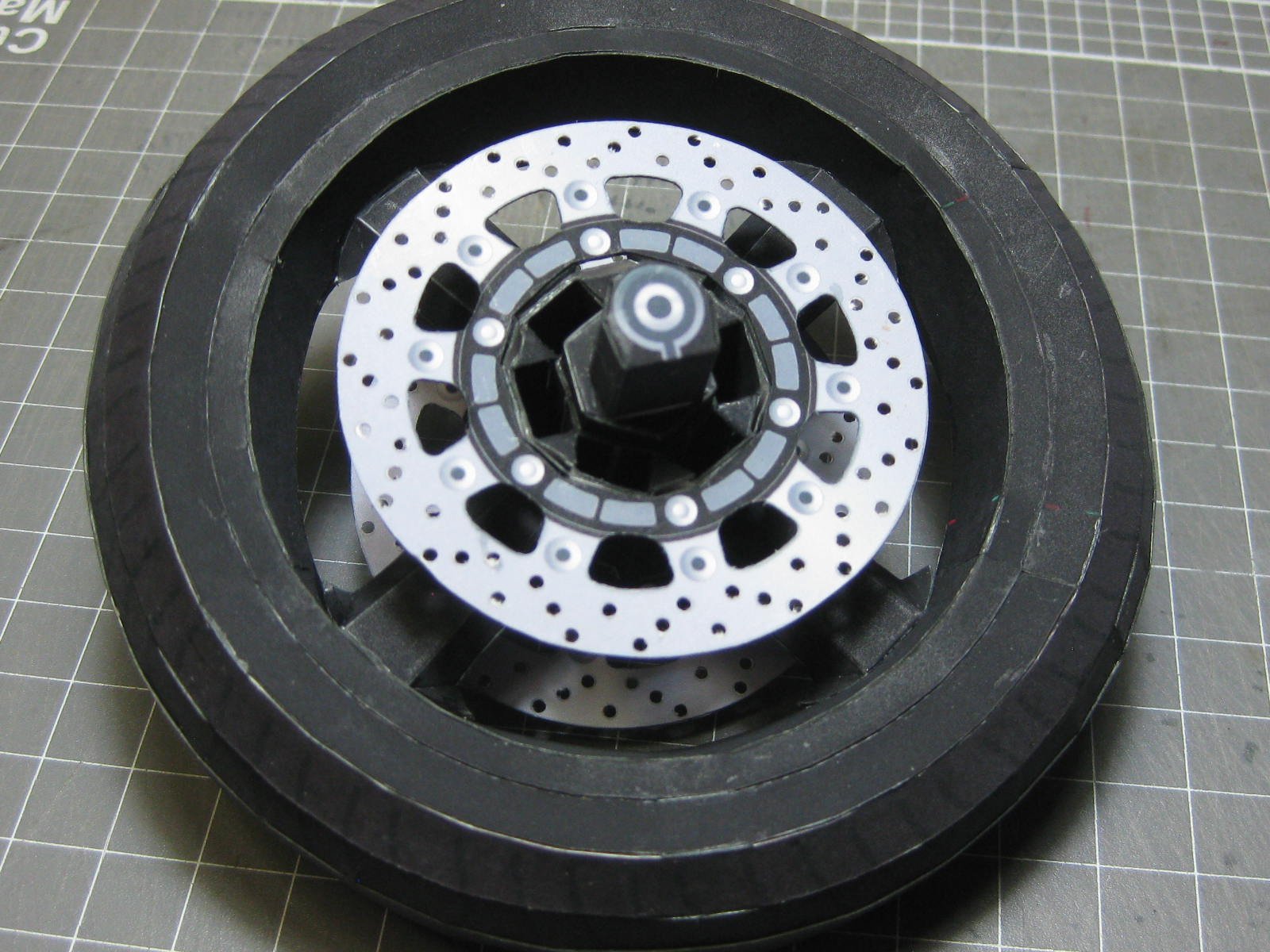
The completed front wheel :
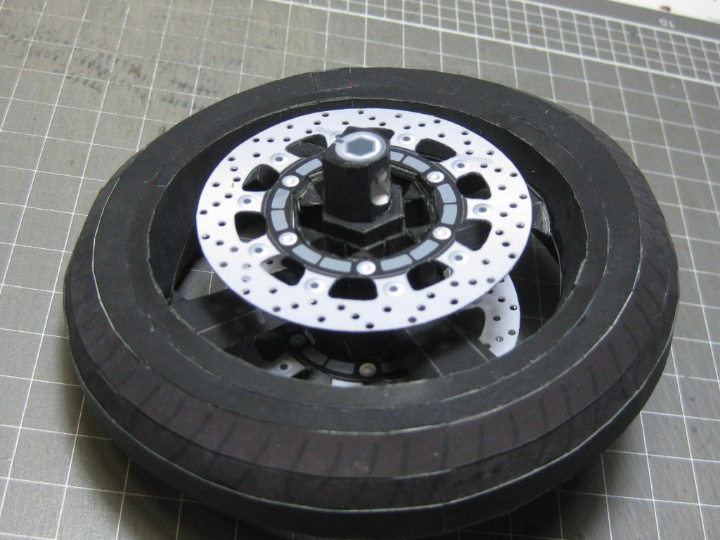
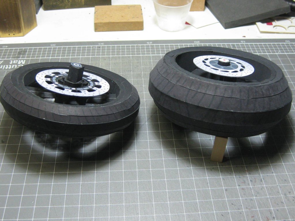
And the HUGE rear wheel. I'm fairly happy with the way they turned out, so the build will continue
:

The two wheels for comparison :
Danny
- popeye the sailor, ccoyle, DORIS and 11 others
-
14
-
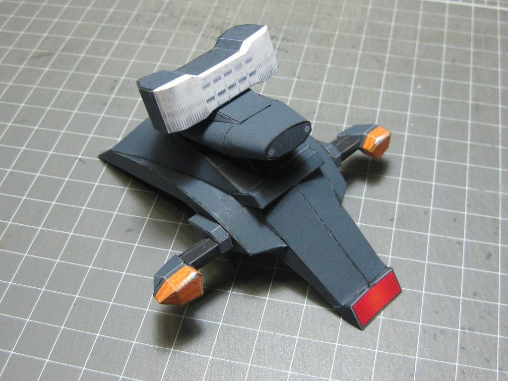
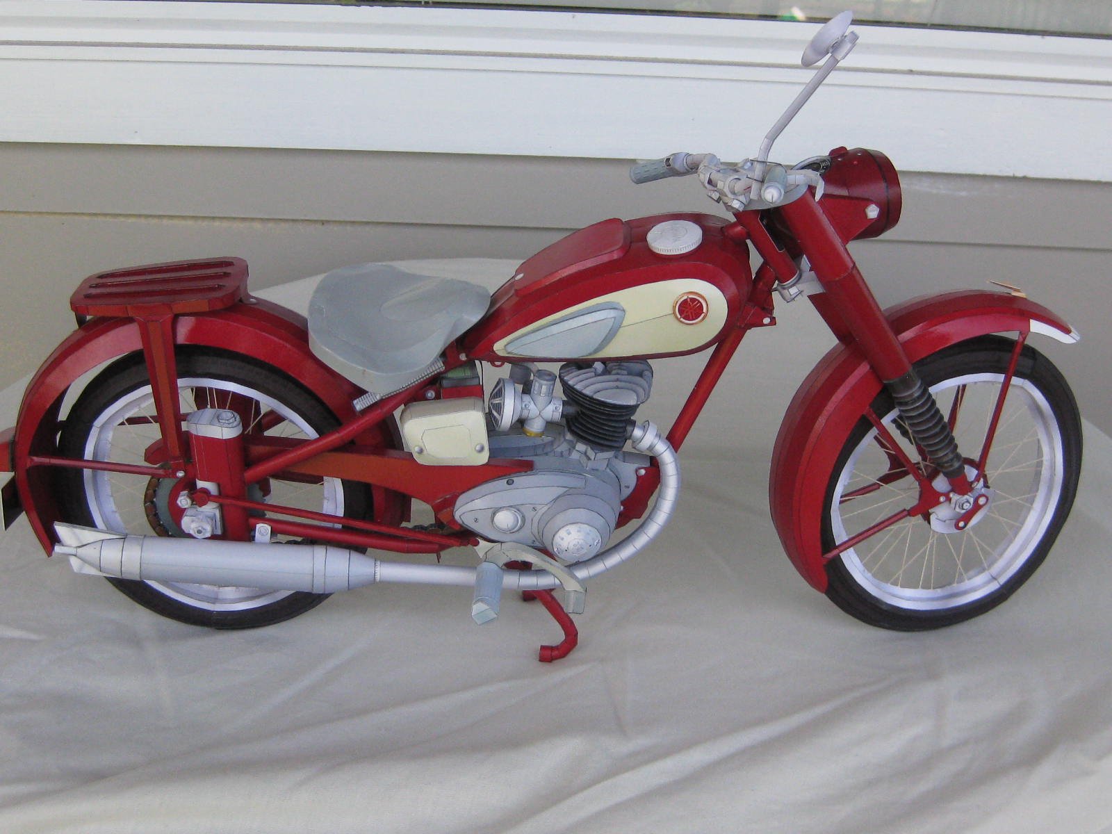
The model is now finished. I coated it with clear gloss from a rattle can. I'll build a stand for it, as it's rather difficult to pick up without damaging anything. The actual stand on the model is rather fragile - I've broken it several times already, but I managed to glue it back together each time.


Next model will be another Yamaha - the MT-01 (2005 - 2012) model. I've already made a start on it, and I'll post some pics shortly.
Danny
-
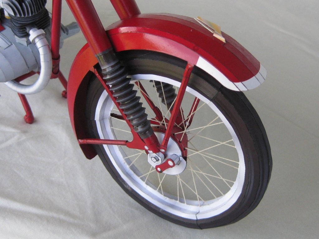
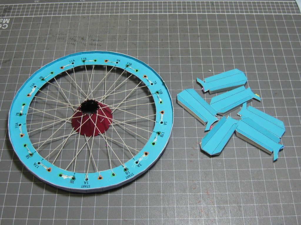
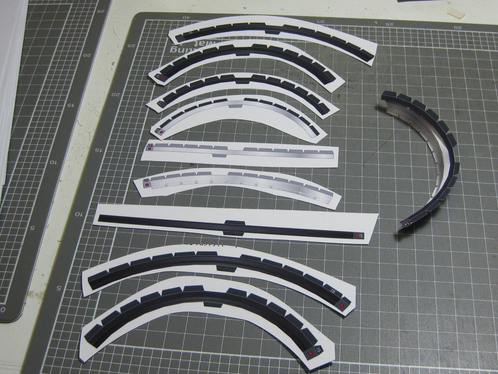
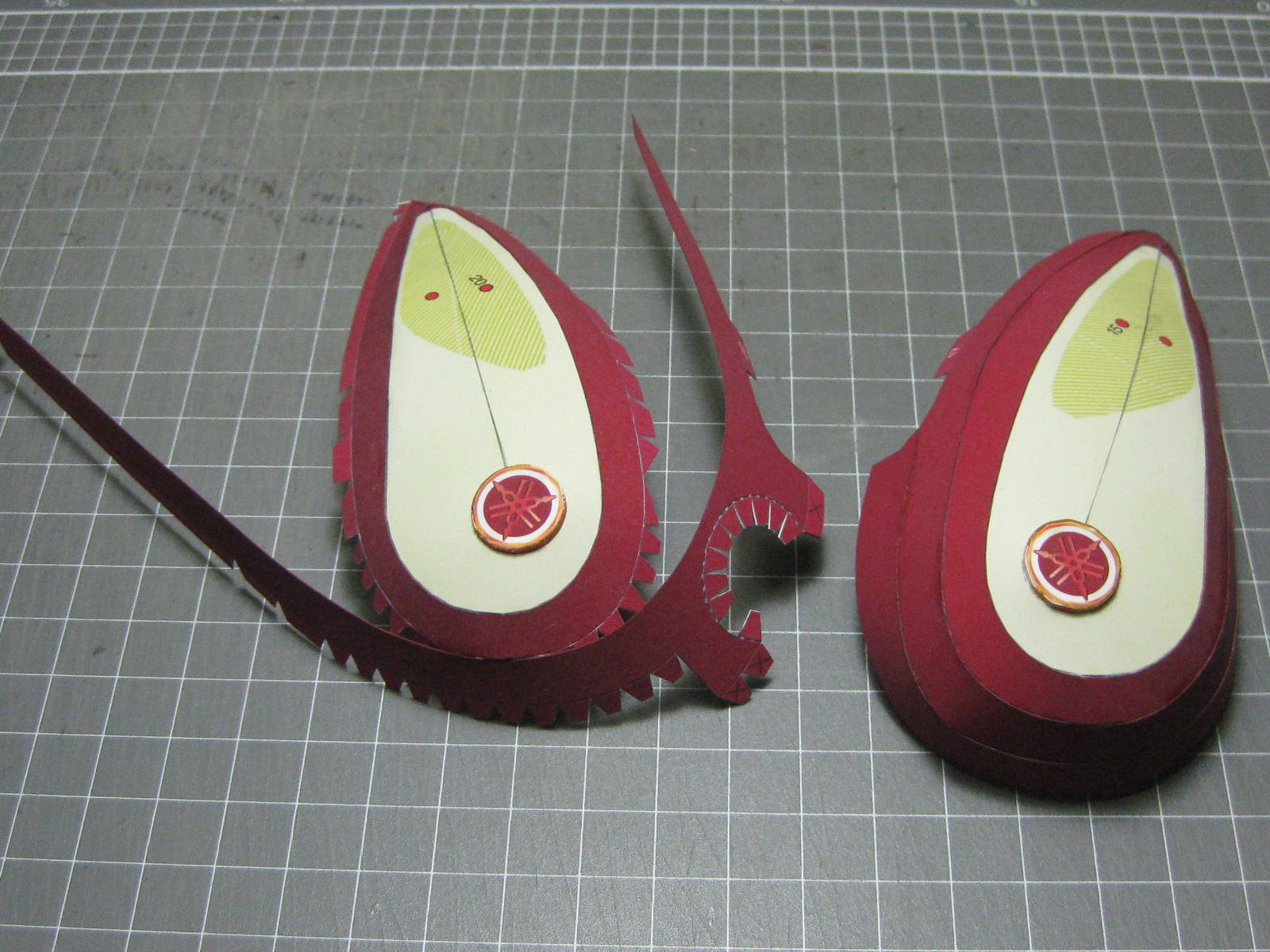
Next up is the hardest part of the whole build _ the wheel/tyre combinations. If I'd have done these first I wouldn't have continued with the build. The design is very poor to say the least (it's much improved on other motorbikes in this series) and I'm not very happy at all with the way they turned out. But it is what it is - I won't be re-making them.
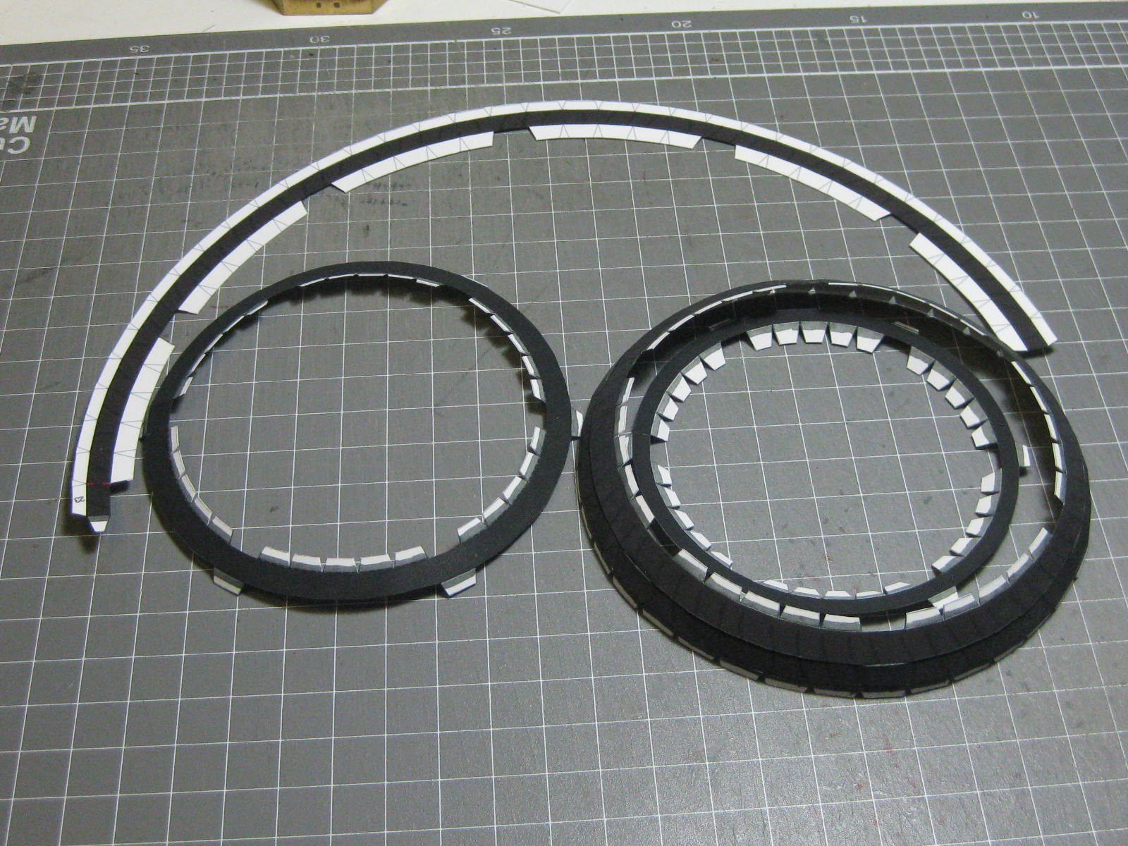
Here are some of the pieces for one of the wheels :
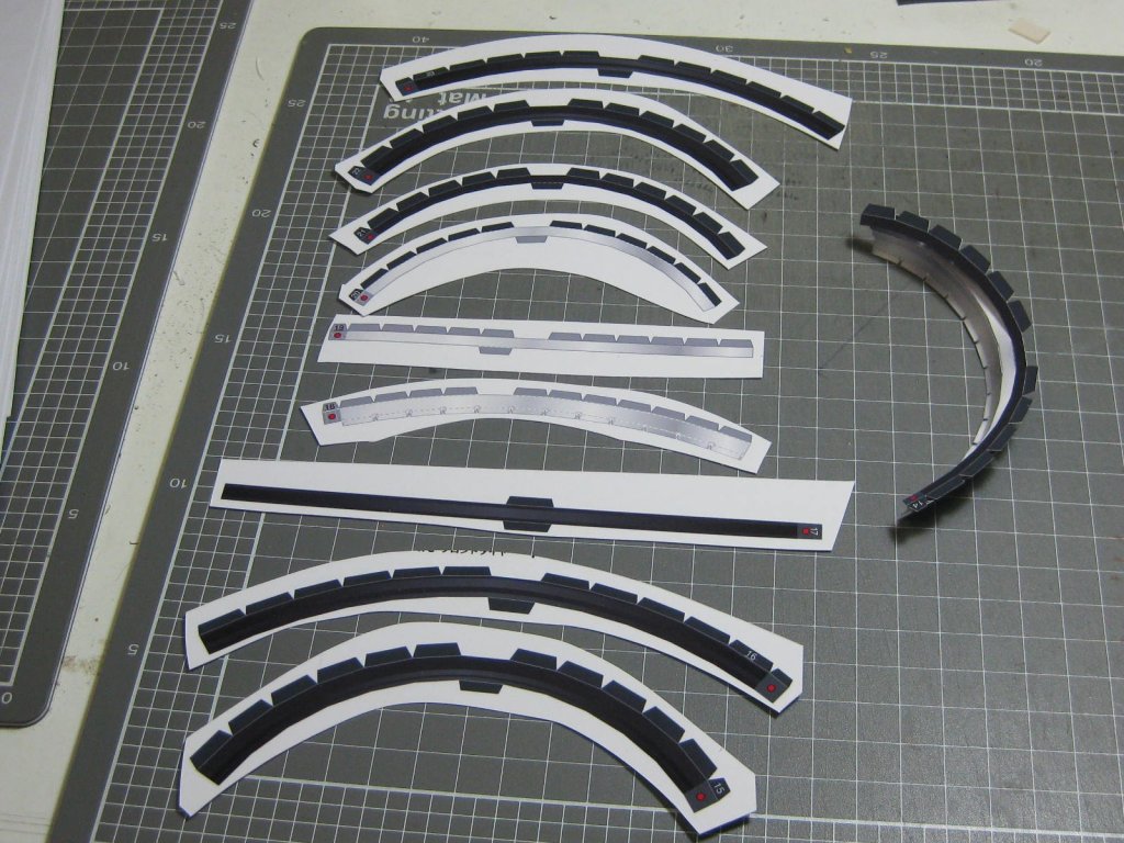
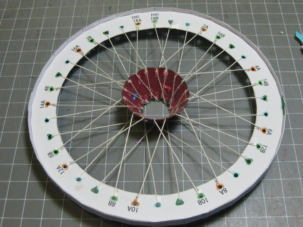
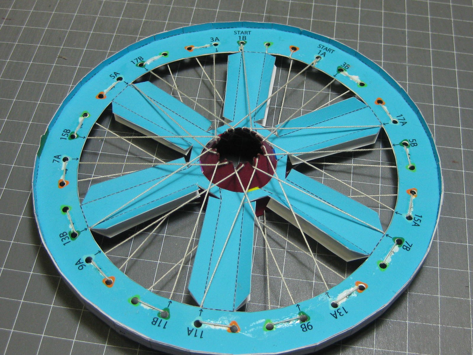
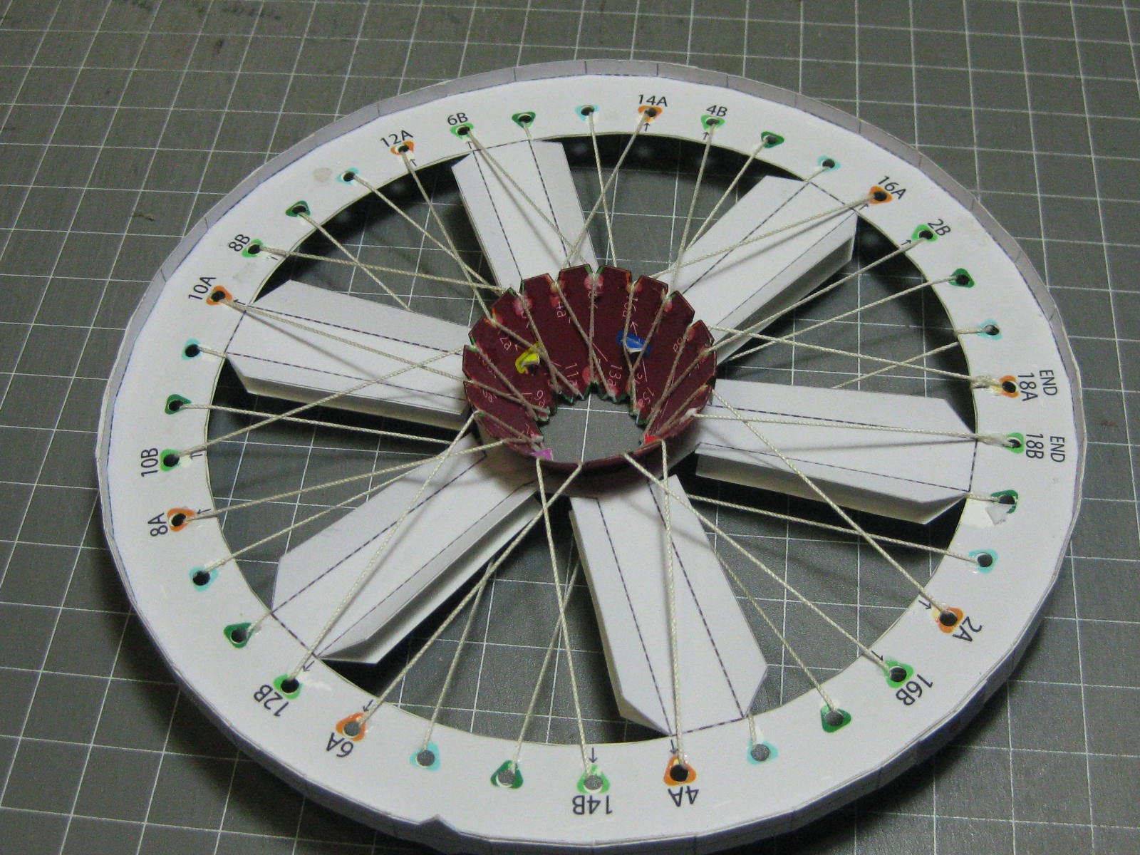
As this model Yamaha has spoked wheels rather than the mags of later models work starts with a "frame" that holds the hub and spokes. Why they chose that horrible aqua colour is a mystery, it gave me a bit of grief later on. If they were light grey it would have been a lot better :
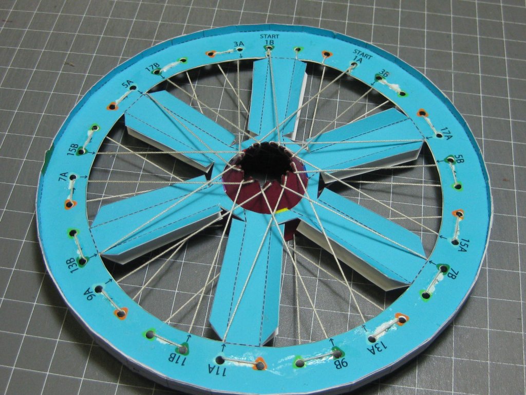
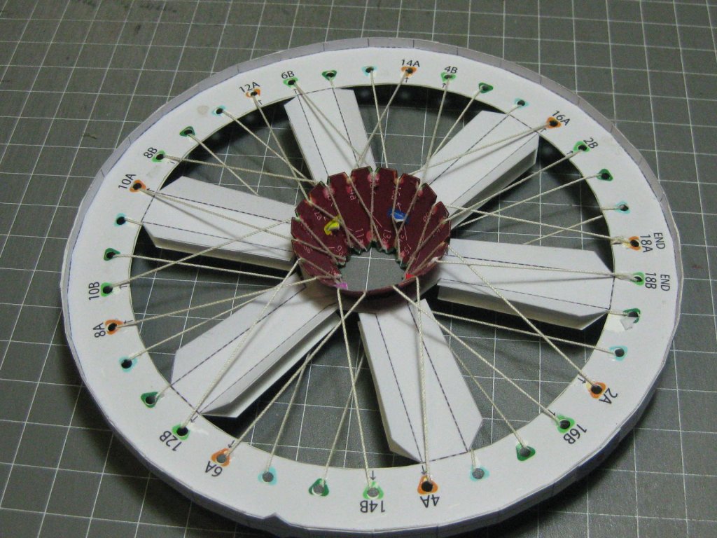
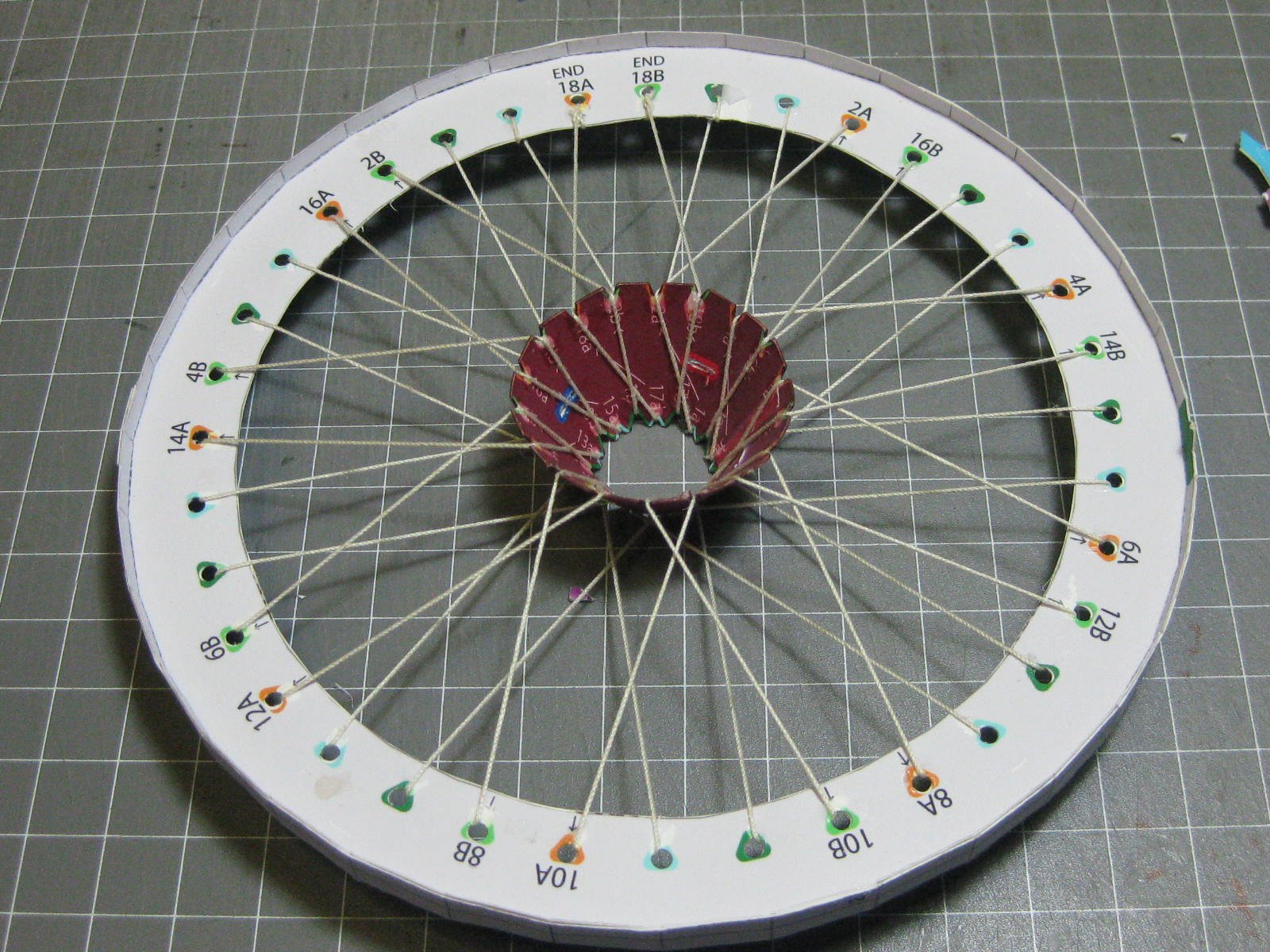
Once I'd finished the spokes, for which I used mercerised cotton, the temporary spokes were cut off :
That was all the progress pics I took - the following post has the pics of the finished model.
Danny
-
It's been a long time since I updated this log, but I've actually done quite a lot as you'll see. The battery in my old camera failed and it took me a while to find a replacement
 .
.
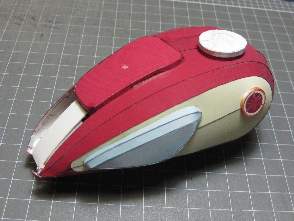
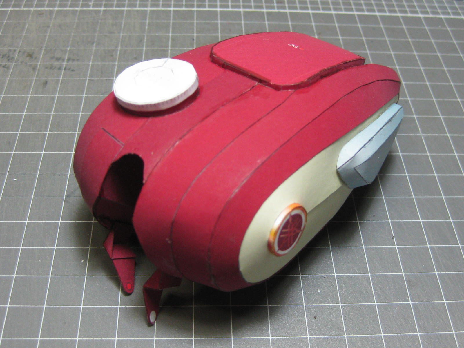
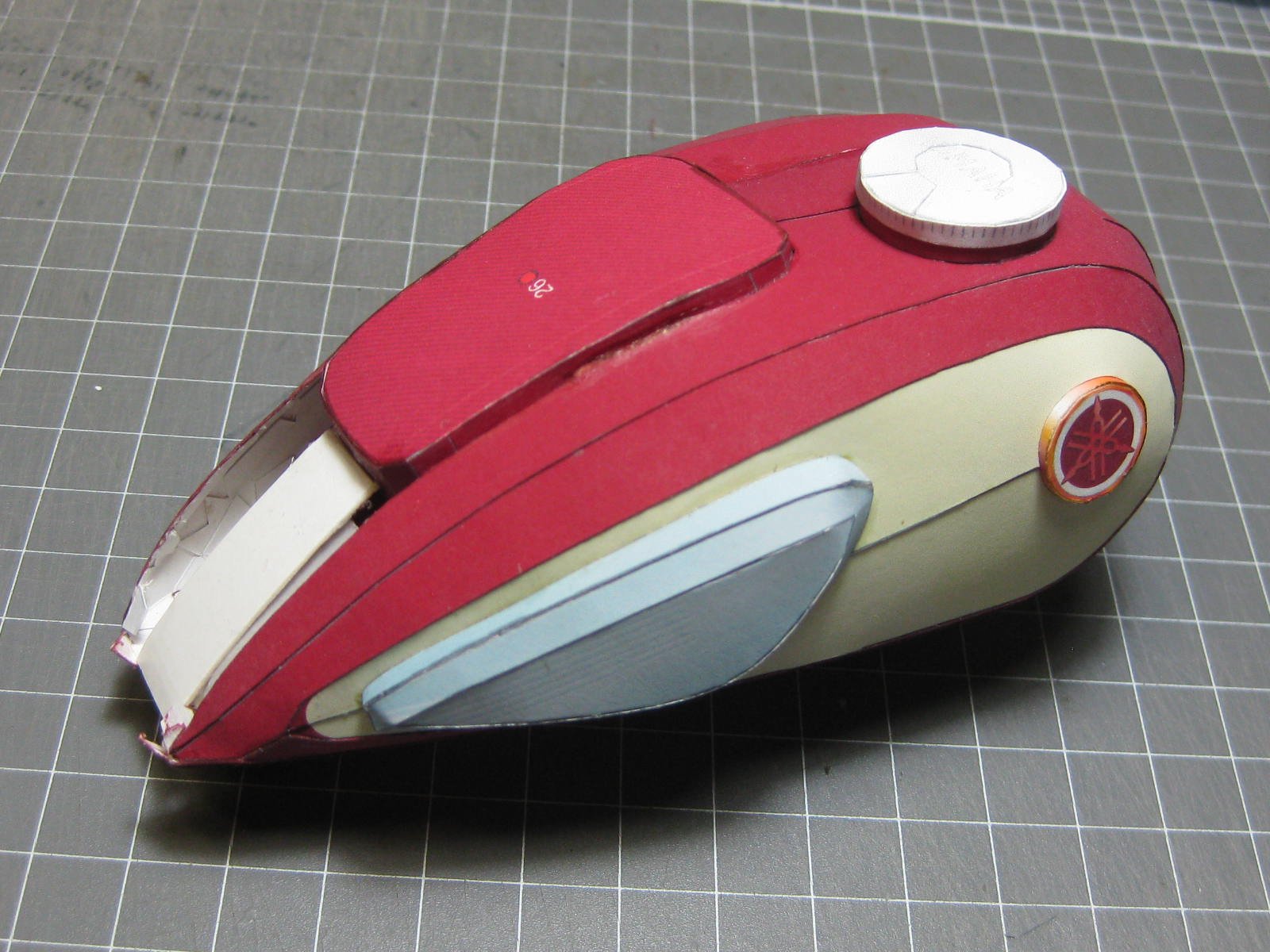
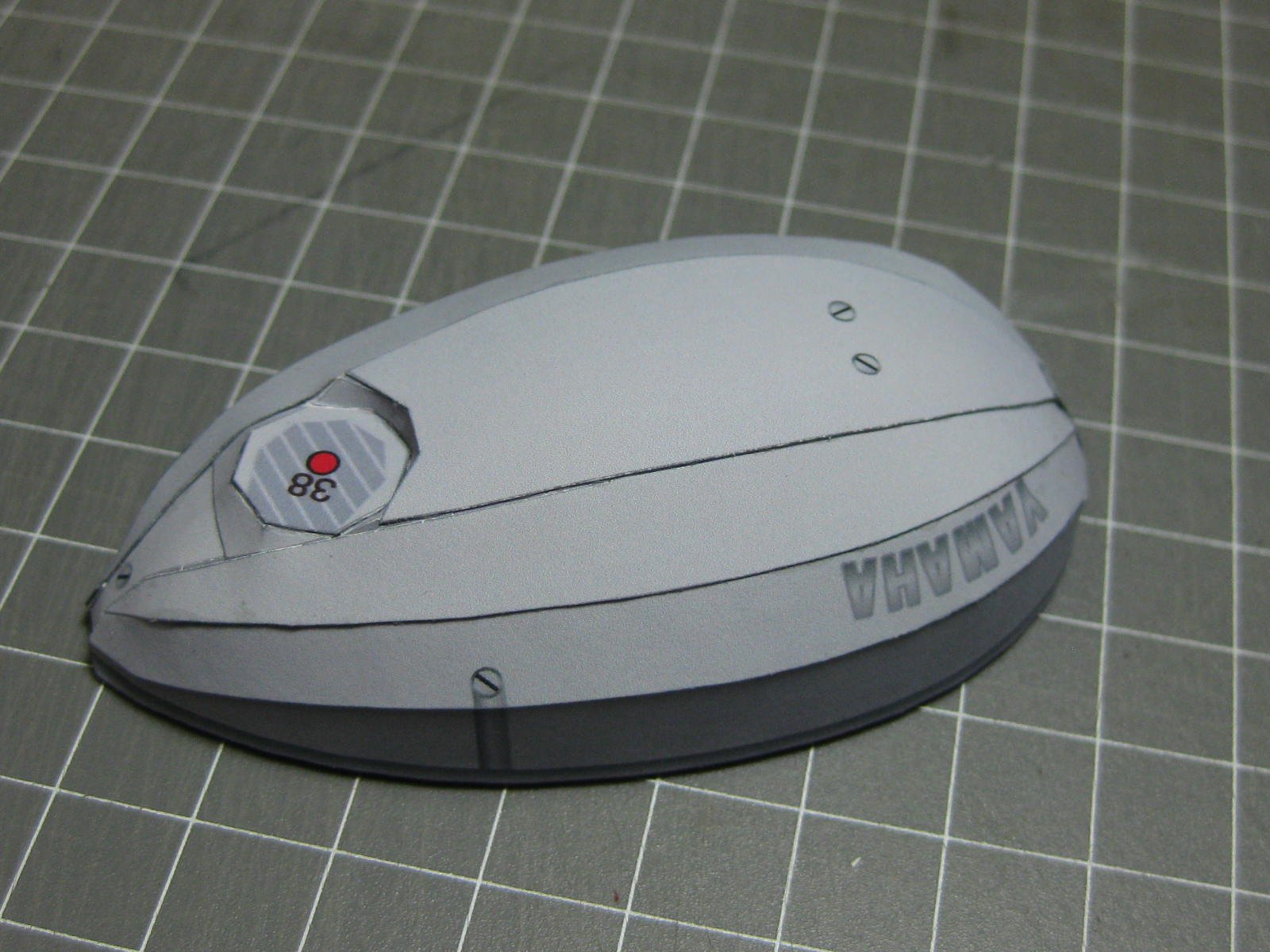
The fuel tank is finished, although I had to cut off a couple of pieces, re-print them and glue them back on which I did after taking these pics :


The chain took a while to make, but I'm really happy with the results. I only glued on the front and rear sprocket pieces at this stage, the straight bits came after the engine was fitted to the frame :

A few of the smaller pieces. This is the piece that made up the gearshift pedal :
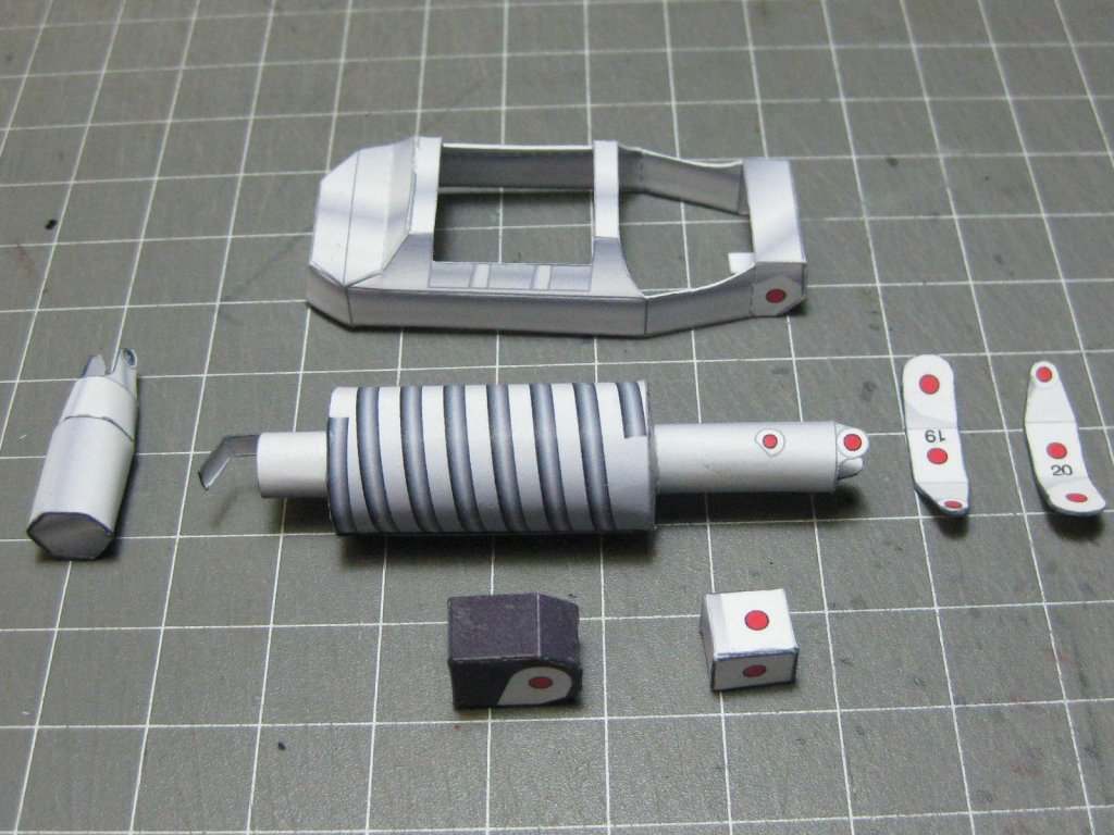
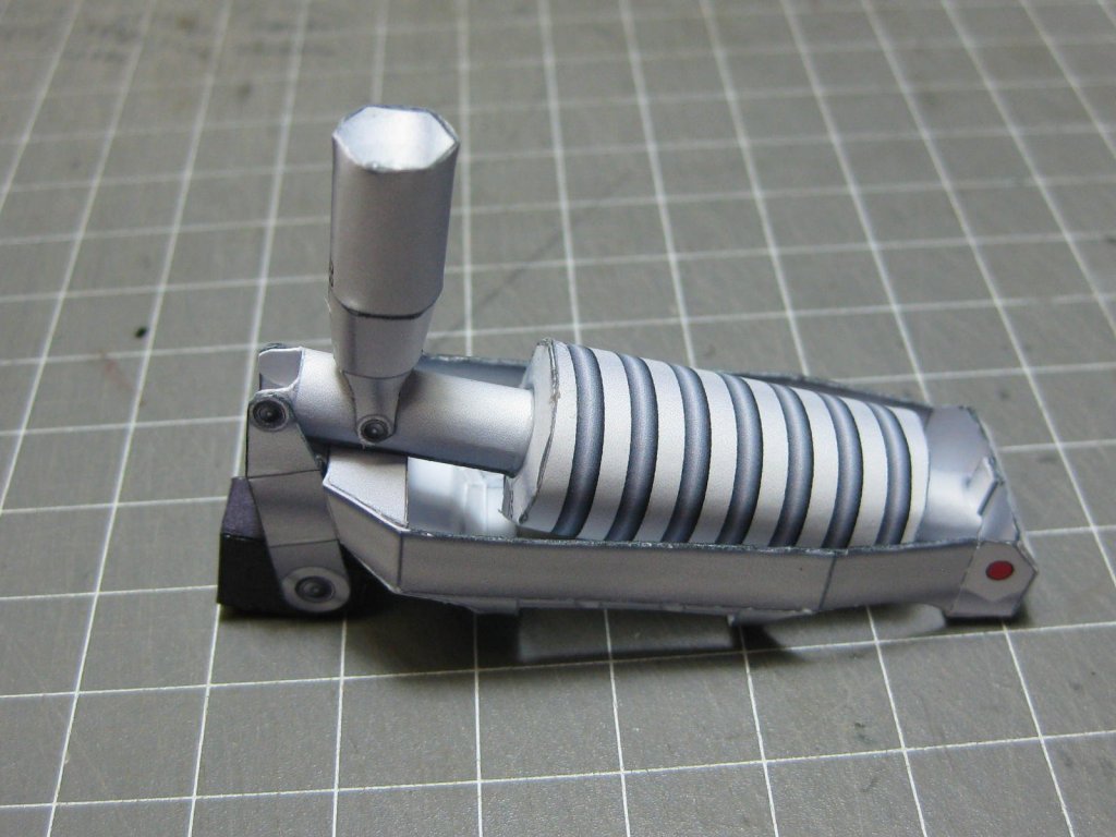
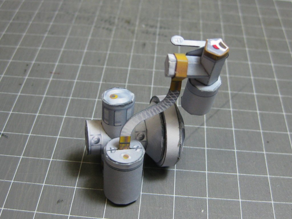
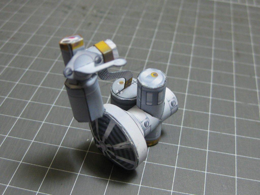
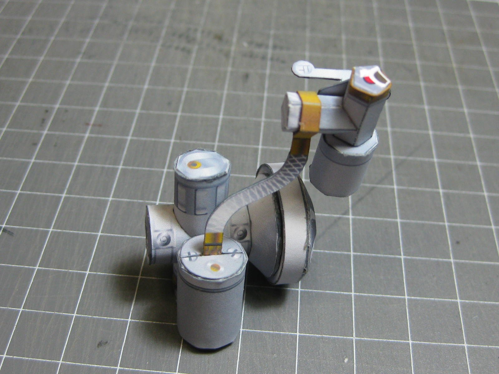
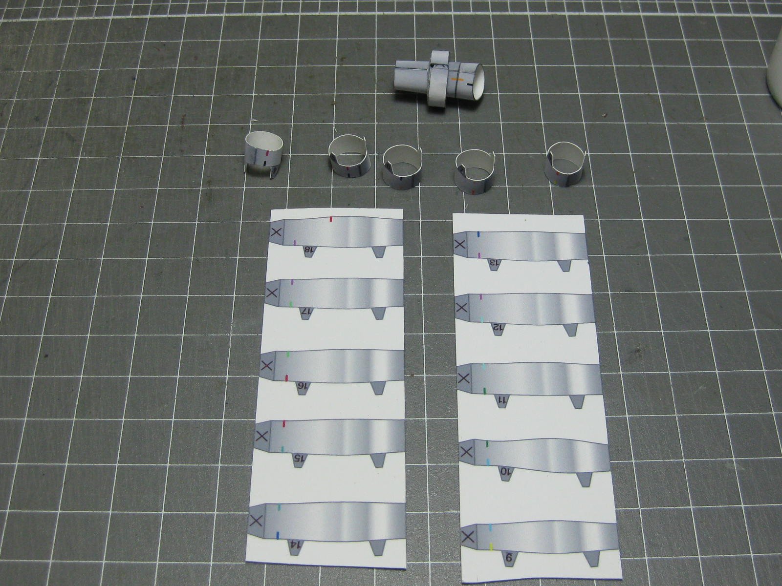
The carburettor and fuel filter :
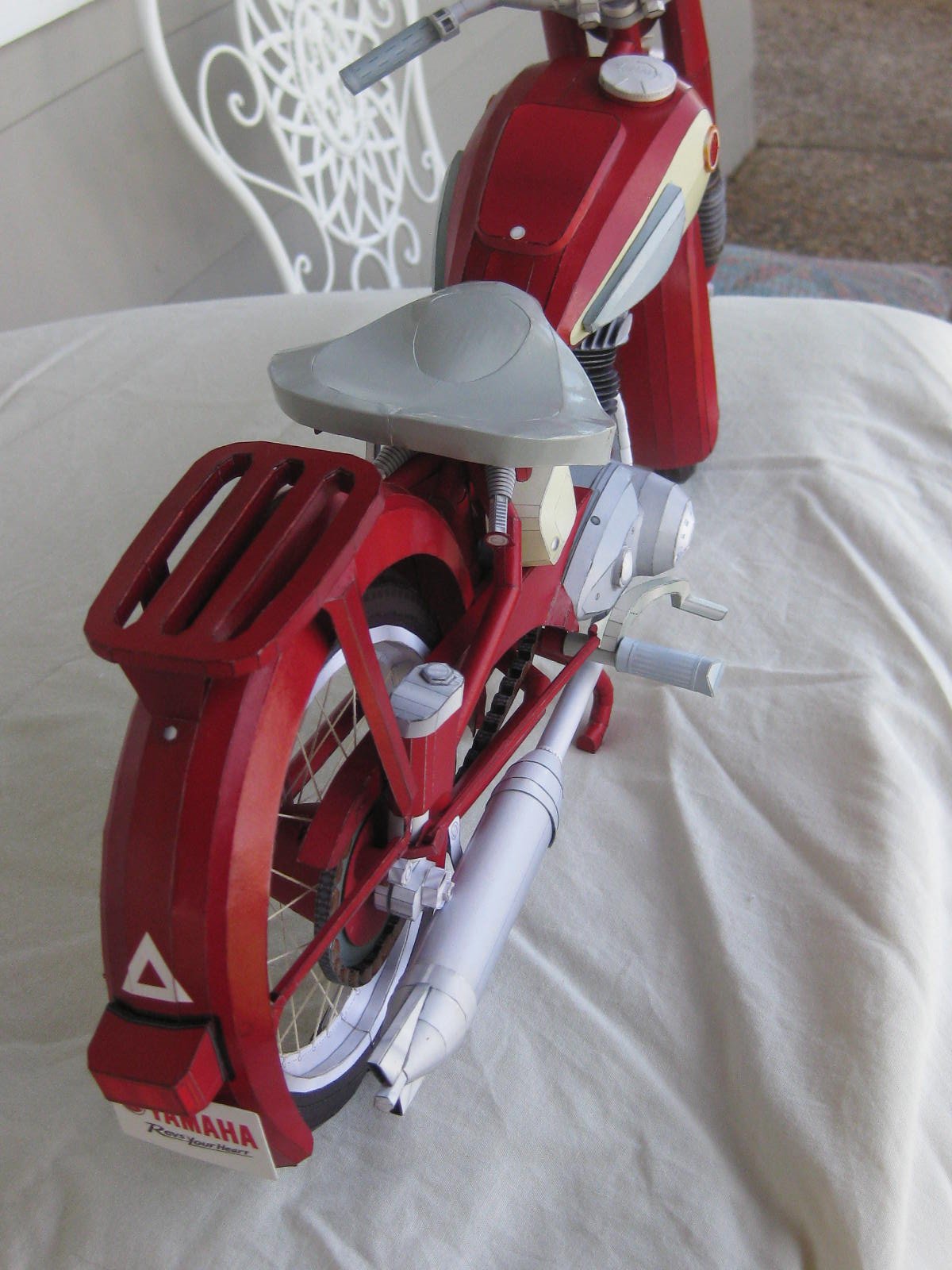
The rear mudguard. It is lined on the under side, the same as the front guard :


The rear rack :

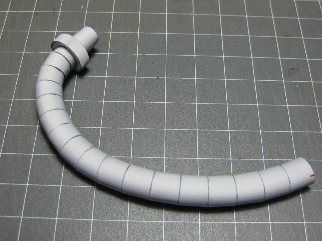
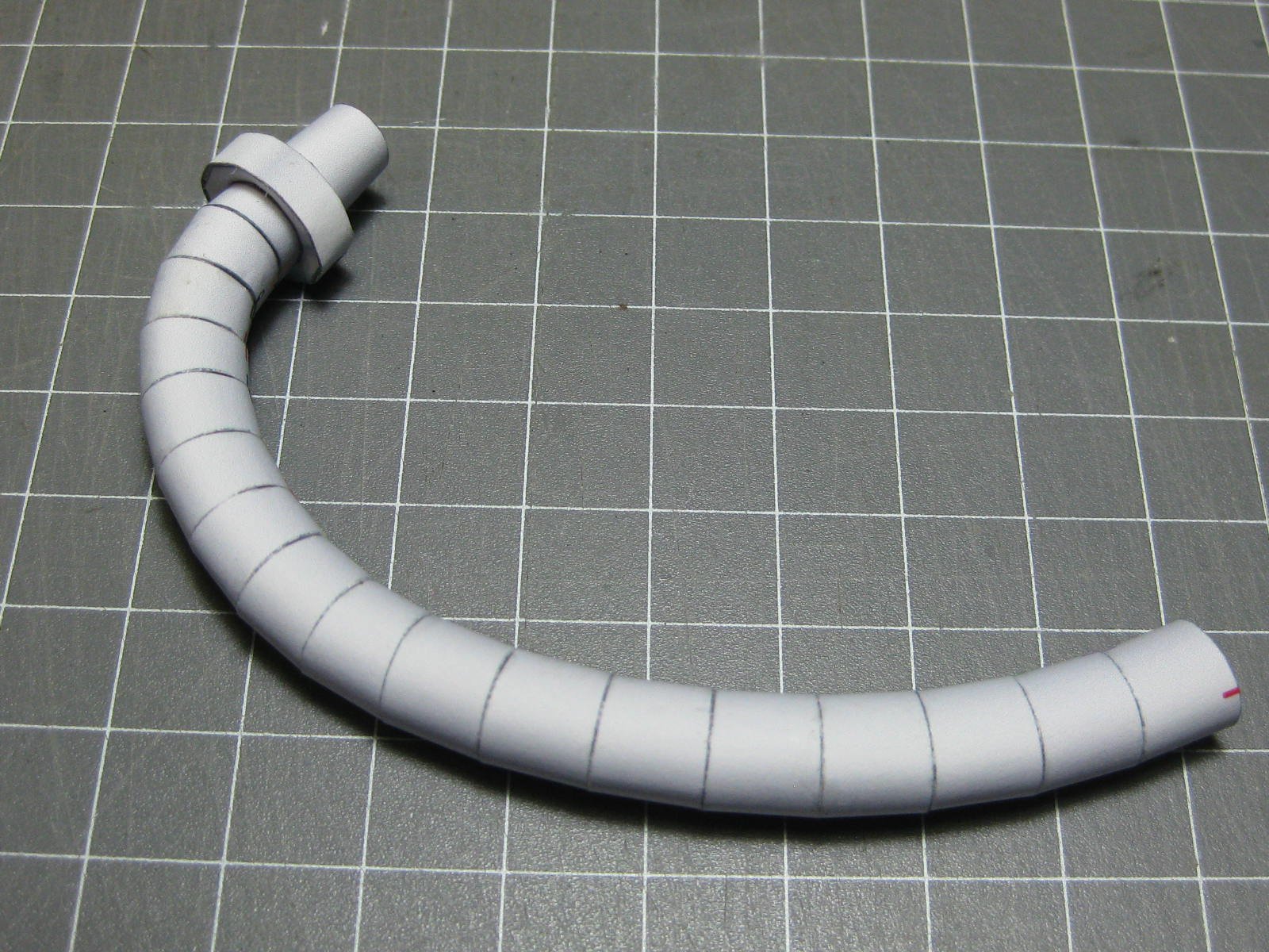
And finally for this post - the exhaust header pipe :
- popeye the sailor, Canute, Richmond and 4 others
-
7
-
6 hours ago, Jobbie said:
Each other plank on the stem will follow their natural lay, with stealers placed in between.
You will definitely need a few stealers because of the bluff bow. You might have gone a bit far with the upper planks already, but it will give you a good indication of where to start adding the stealers with the 2nd planking. Pretty good job so far
.
BTW - I always start my planking from the keel (garboard plank) and work toward the wales.
Danny
-
10 hours ago, Richmond said:
it is a reminder to keep your work area and hands clean. Not such an issue on something that will be covered but a good discipline to have throughout the rest of the build.
Absolutely
.
10 hours ago, Richmond said:Another issue is over handling - the more you handle the poorer state the parts end up with. I really need to reduce the amount of dry fitting next time around.
This is very true, especially on hull skins and the like. Once you crease a piece it's almost impossible to get it out again.
10 hours ago, Richmond said:I haven't seen any thin CA in our local DIY Chain; for any Australians out there can you get thin CA in Bunnings?
More than likely, but I wouldn't bother too much. I don't use it for anything other than gluing Photo-etch. I use PVA glue exclusively, an acid-free Craft Glue that's a fair bit thicker than wood glue. It comes in various brands, mine is "Mont-Marte" and is available in Craft stores (which may be a problem in Darwin
, but try Spotlight at this address : Jape Homemaker Village, Tenancy 7E, Bagot Road, Millner, Darwin. My local ones have a good selection of Craft supplies).
Danny
-
17 hours ago, Richmond said:
the horizontal structure each side of the lateral - I assume I would have cut these off at the stern section of the hull as they wouldn't be required anymore?
More than likely, if they are a problem or nuisance.
Danny
- Richmond, mtaylor and GrandpaPhil
-
3
-
Hi Richmond,
You have gone way beyond "the contract" with the hull framing. It's not necessary to clear-coat it for one thing - save that for the visible pieces.
8 hours ago, Richmond said:The design of the end bulkheads left a little to be desired, with the proximity of horizontal and vertical slots undermining the stability of the structure.
A common problem with some kits. If you do another card model after this one, consider using Laser-cut framing if available - it saves a LOT of work, and is reasonably priced.
A solution would be to fill the entire bow/stern section with card or balsa and sand to shape.
8 hours ago, Richmond said:I am really not sure if the voids need to be filled with foam to provide a better base for applying the skin, hopefully we can discuss at a later juncture.
I would be avoiding foam (although I've never actually tried using it). If there are any unstable bulkheads then glue some extra card between them longitudinally. DO NOT glue the hull skins to these. You can bring the extra card bracing out to the (inner) level of the skin to help with avoiding accidental crushing when picking up the model, but leave it unglued from the skin.
When I first started card building I glued extra card to the faces of the bulkheads for a larger gluing surface. This proved to be a mistake, as you need to use as little PVA as possible to avoid the "starving cow" effect. The glue tends to pull the skins inward alongside where it meets the bulkhead. 1.5mm thick bulkheads are more than adequate for gluing two sections of hull skin together, even though they may not look like it at first. You will get better at gluing thin card edge-to-edge as you gain practise.
Danny
- GrandpaPhil, mtaylor and Richmond
-
3
-
20 hours ago, Dziadeczek said:
Dan,
May I ask what type of paper do you use for printing the designs? Regular, extra thick, matte, glossy photo paper...?
I'm using Matte Photo Paper - 170gsm weight, which measures at 0.25mm thick.
Danny
-
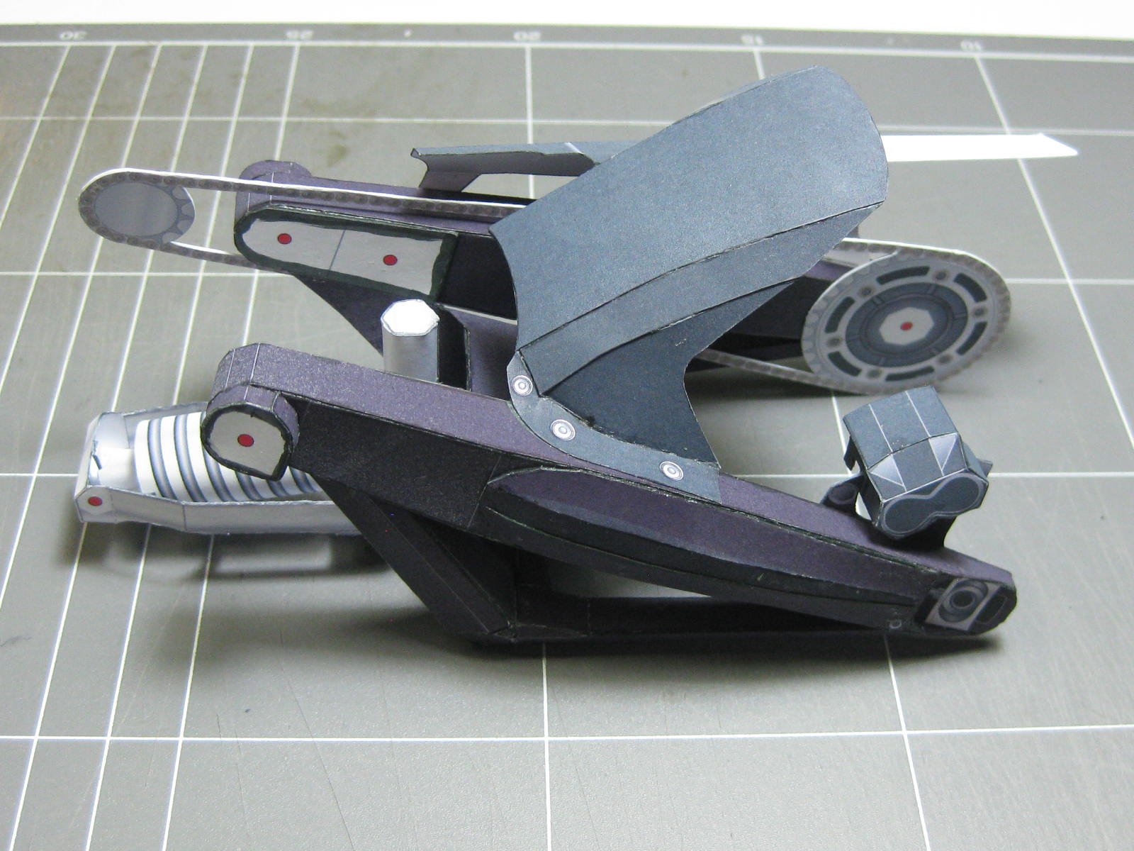
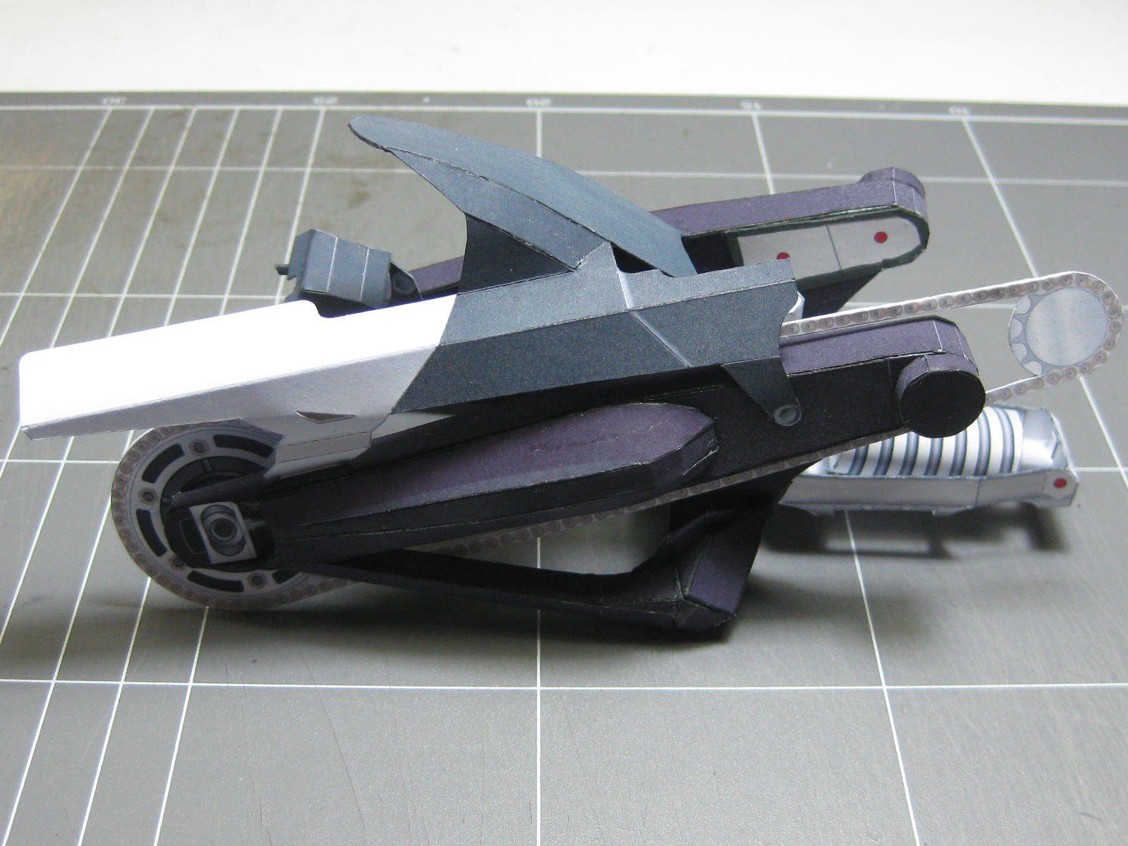
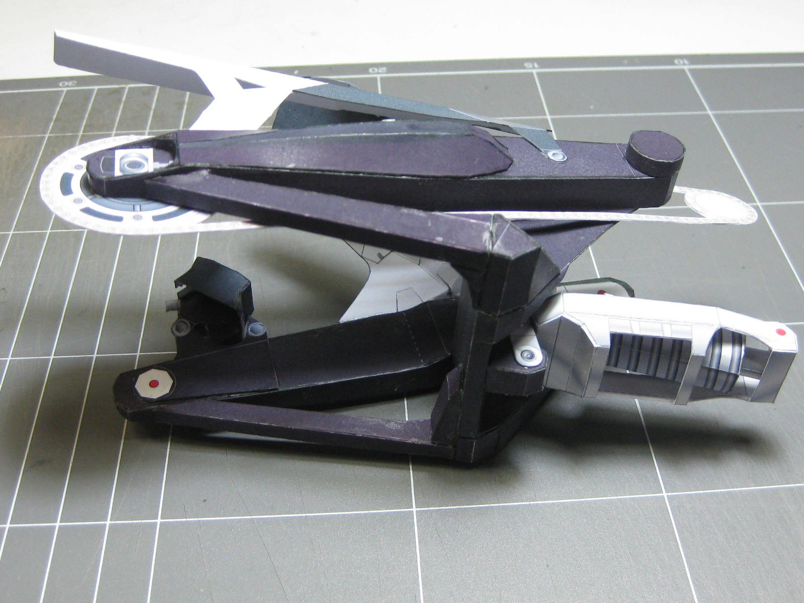
A couple more steps in the build - the Fuel Tank, Drive Chain and Engine :


The tank still needs a couple of pieces to be added before it's finished. I need to re-print a page for one part, which I'll do when I get more photo paper :
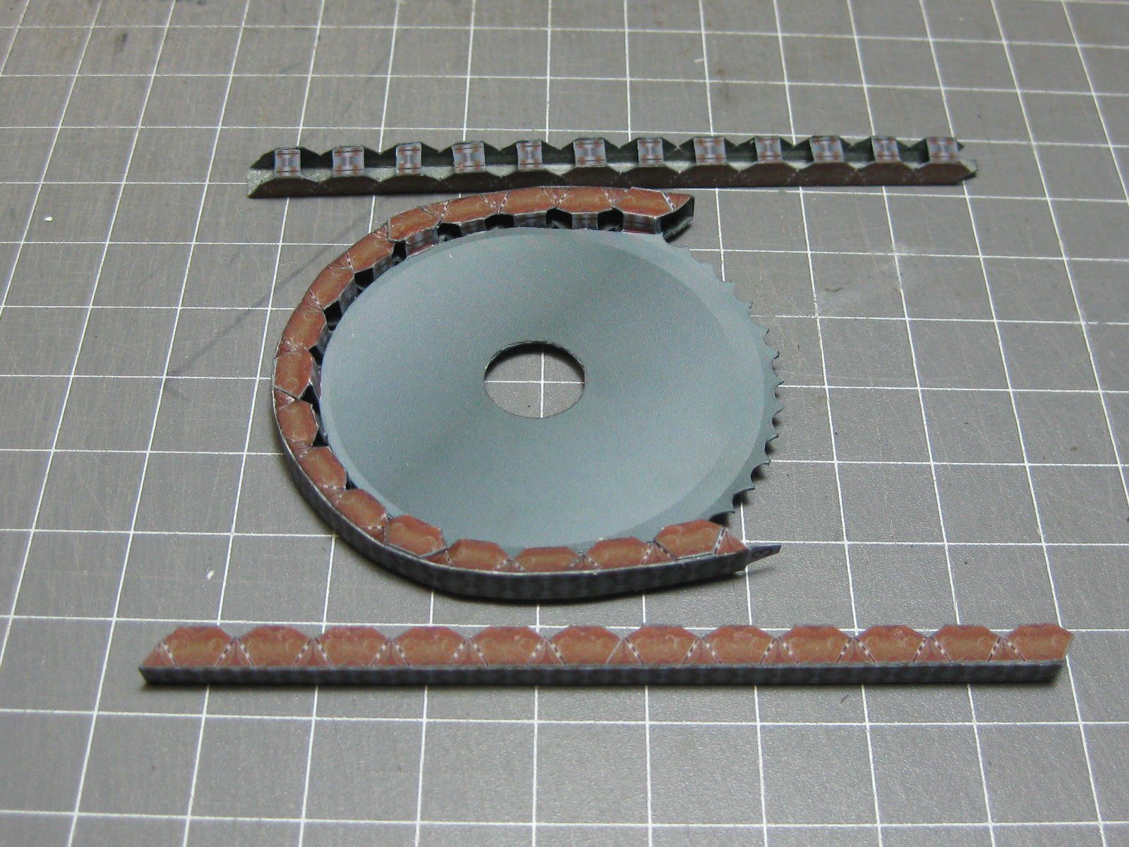
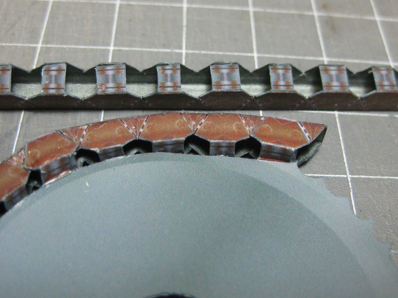
The drive chain comes in several sections, and takes some cutting. It's actually easier to make than it looks
:
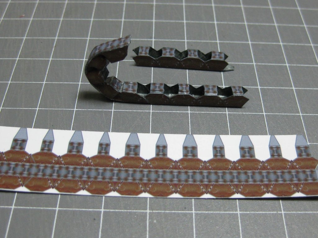
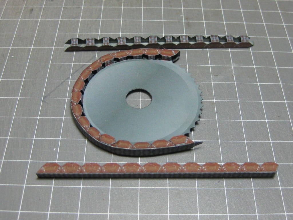

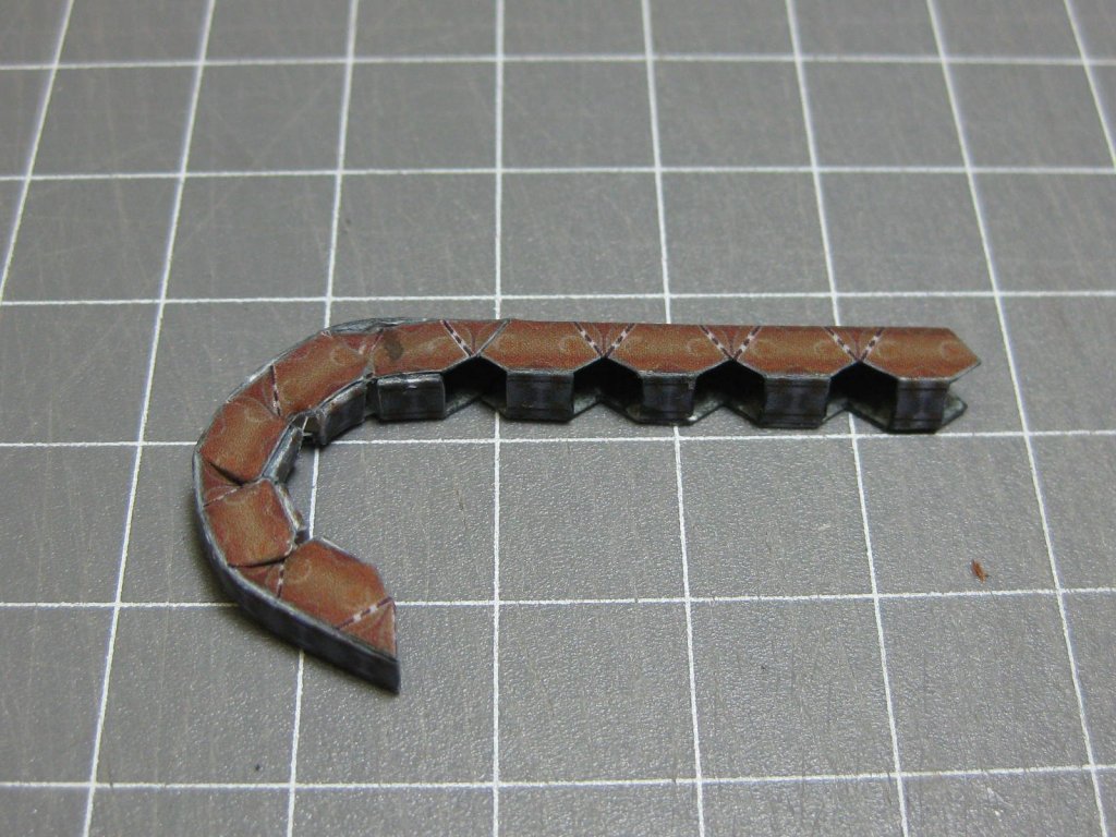
The curved sections of chain need to be squeezed in and glued between the links :
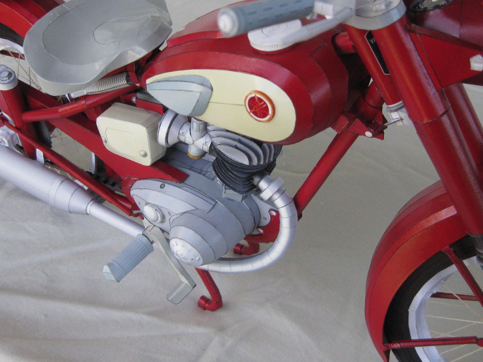
The Engine took me three days to build. The crankcase hasn't turned out too bad, considering the different sections in it :

I fitted the forward section of chain before gluing on the R/H crankcase cover, it would have been impossible later on :

Danny


Yamaha MT-01 by Dan Vadas - CARD - FINISHED
in Non-ship/categorised builds
Posted
Thanks David, Jan and Nils") . Jan, I've seen the Ferraris before but I can't remember the site they can be bought from. Do you know what it is?
. Jan, I've seen the Ferraris before but I can't remember the site they can be bought from. Do you know what it is?
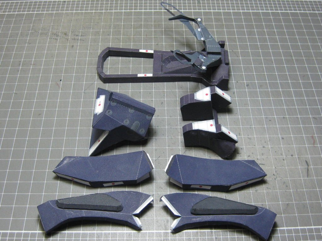
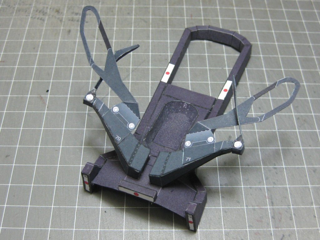
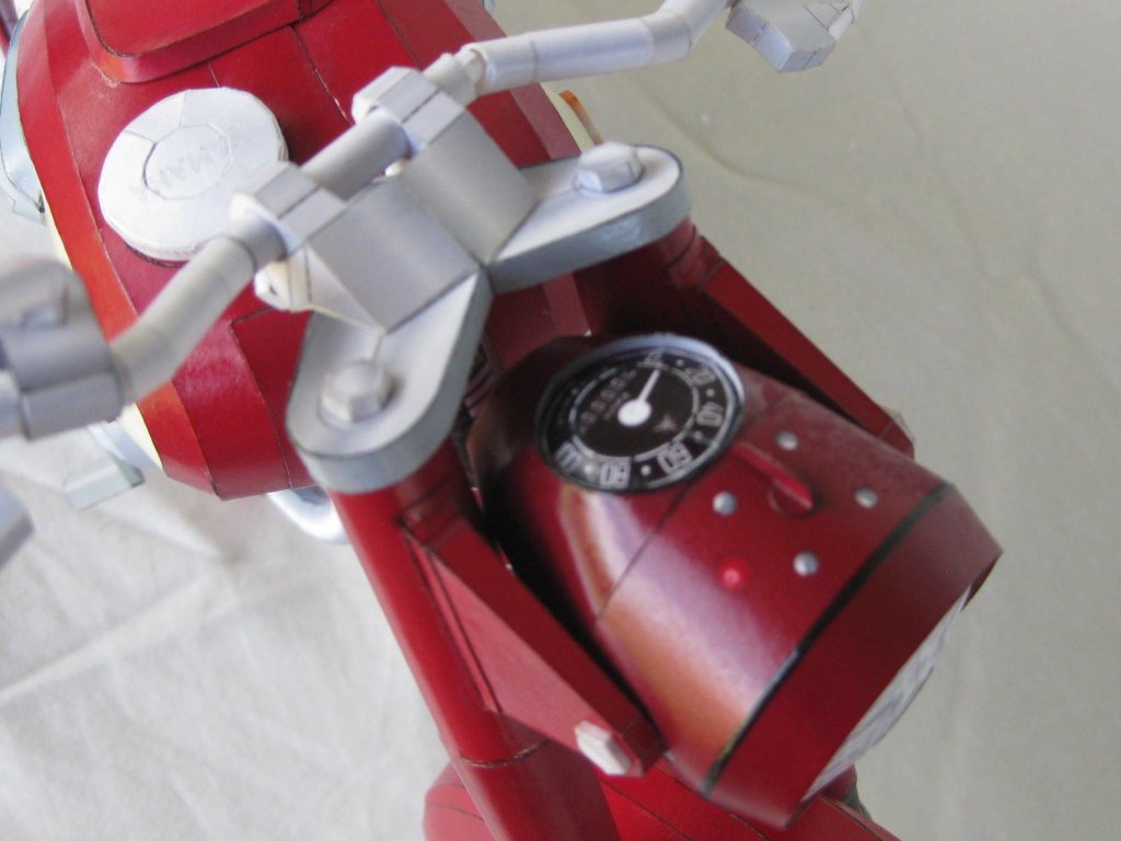
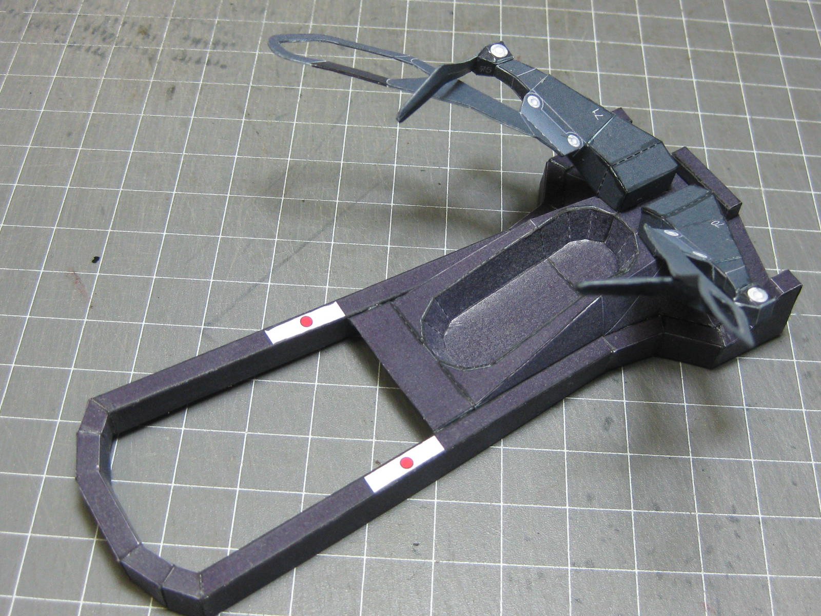
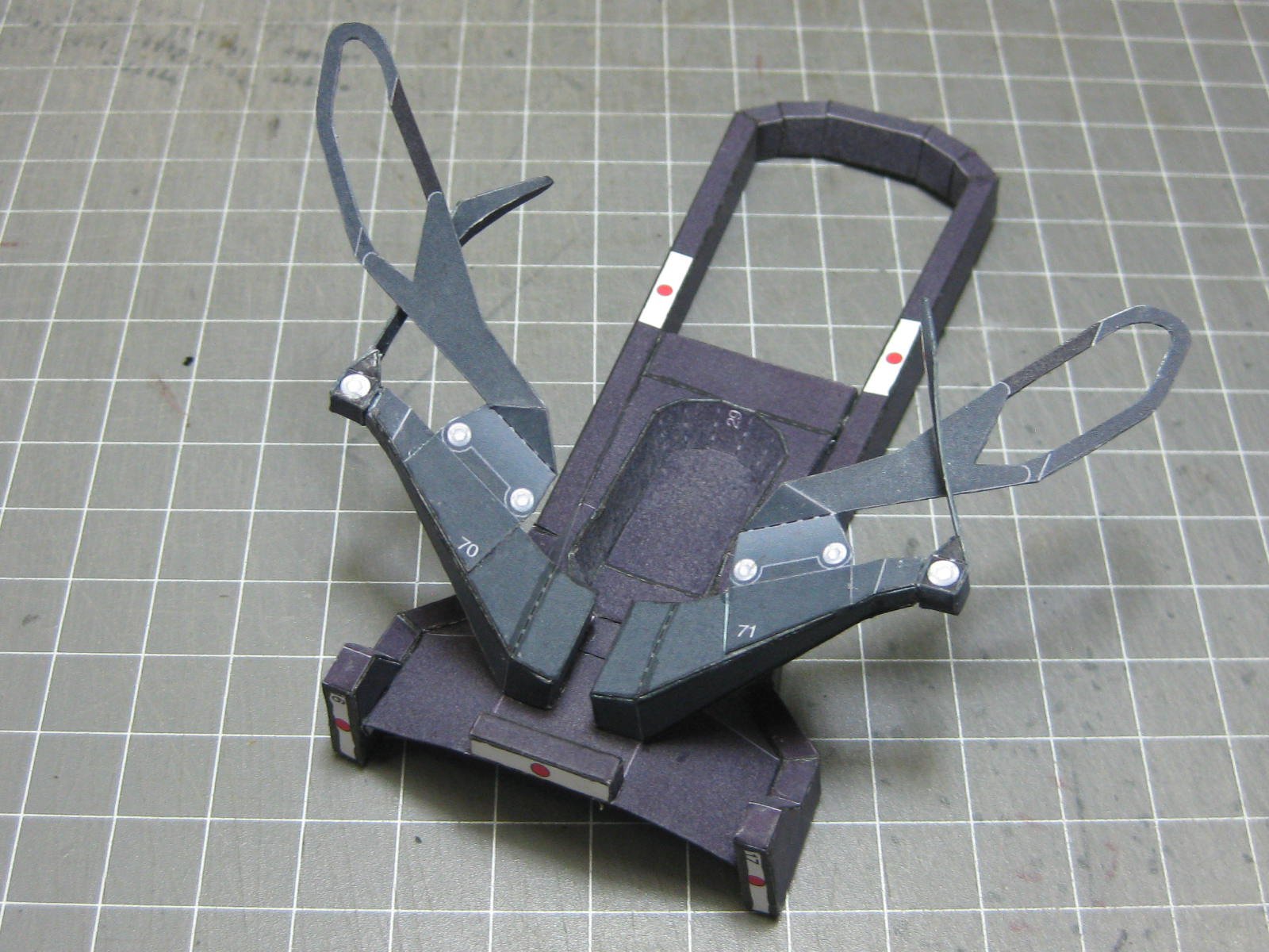
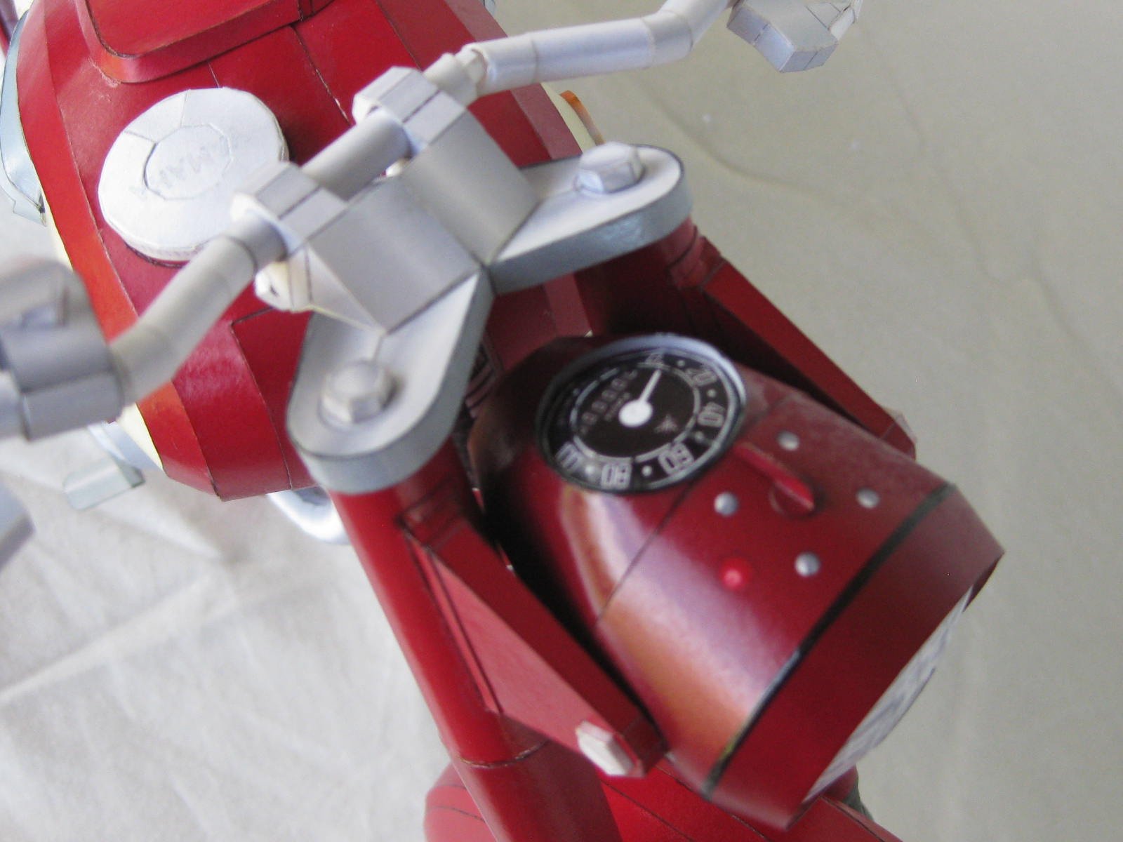
This is the front suspension, steering and handlebars. The top bracket has not yet been glued in, as it needs to go through a tube at the front of the frame to enable the steering to turn. I actually made a mistake with the previous bike, gluing it in this stage, and had to cut it apart again. Lesson learned") :
:
Danny