
Thukydides
-
Posts
1,272 -
Joined
-
Last visited
Content Type
Profiles
Forums
Gallery
Events
Posts posted by Thukydides
-
-
-
-
The figures look good. Nice and neat, great job.
A small thing you could do next time to give a bit more depth is try using some washes (particularly for the skin). They are super easy to use and will help the models pop more for only minimal more effort.
-
-
It has been a while since I posted as I havn’t had any progress to report. Life has been busier and I have been spending most of my hobby time doing research for Perseus.
However, this evening I broke out the airbrush and decided to make some progress. I love my airbrush, but I dislike the setup and teardown I have to do with it and so I often have trouble finding a free evening where I am in the mood to use it.
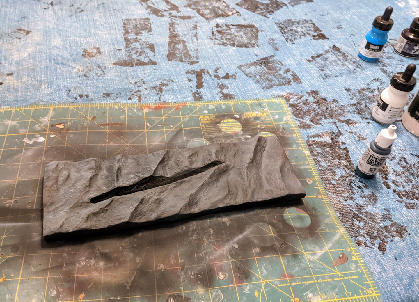
First up is the uboat itself. I primed it black and then gave it a coat of VMC German Grey. In retrospect it looks a bit on the dark side. I may have to give it another slightly lighter coat for the dark colour. Once it has fully dried I will mask it off and spray the lighter grey.

I also primed the water base in black and then gave it a coat of VMC dark sea blue. This did not cover as well as I wanted and ended up just looking a slightly bluey black (see below).
So I broke out my inks and started shading and highlighting with various combinations of cyan, white and navy blue ink. The nice thing about the inks is they don’t cover, but are super saturated so you get lots of colour that you can layer on top of itself. I don’t have any pictures of the process as it is hard to take pictures in the middle of airbrushing, but here is the final result after all the spraying is done.
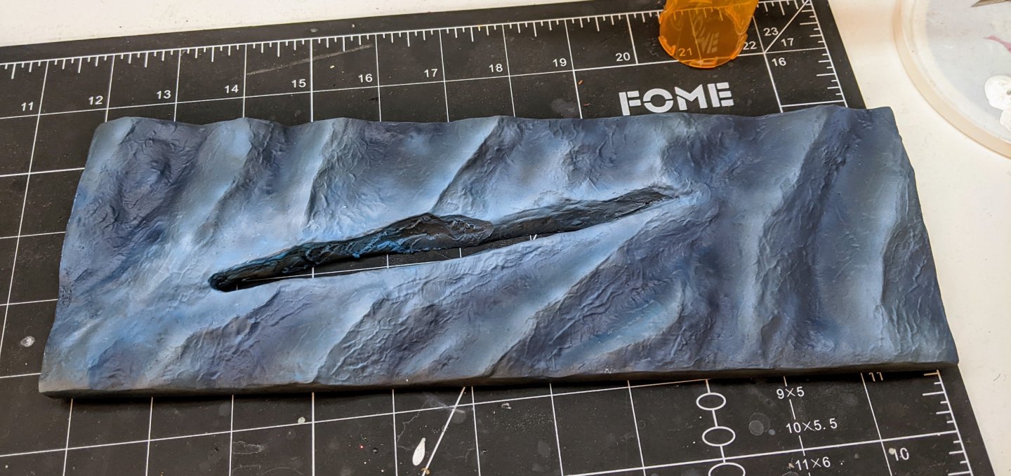
This is not by any means done, I have lots of steps yet to do, but I am encouraged that it looks at least somewhat like water. I will chalk it down as a good first attempt.
- king derelict, GrandpaPhil, AON and 7 others
-
 10
10
-
-
-
If you go to their profile you can see their activity. There is an option I believe to see threads started by them. That is how I would do it.
- mtaylor and Ryland Craze
-
2
-
Log #7: Service History Part V - St. Alban Roy, George Palmer and John Gibson
St Alban Roy
St. Alban Roy was born sometime around 1731 and had a somewhat unremarkable career. He was promoted to post Captain on the 8th of July, 1782 having been given temporary command of the Cato (50) the previous month.On October 21st, 1782 he was given command of Perseus, but no significant events are recorded during his command. Perseus was paid off in March of 1783 and Roy was given command of Perseus’ sister ship Unicorn in August of that year. This was his last recorded service and he died November 1796.
Tobacco Box Depicting Perseus Circa 1782
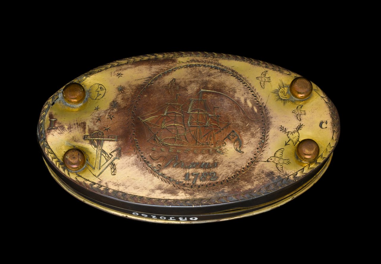
National Maritime Museum, Greenwich, London. OBJ0260.
George Palmer
George Palmer was born sometime around 1755 and had a successful if relatively quiet career. The vast majority of his service was in command of Perseus during the peace.He was posted captain on 18 January 1783 and briefly appointed to command the Surprise (28) before being reassigned to Perseus in July for service out of Liverpool and off Ireland. This command appears to have passed uneventfully with much of the time spent patrolling the coast. The most notable event that can be found in the logs is the loss of the ship’s cutter when a sudden storm hit while attempting to tow the Perseus.
Perseus was refitted at Plymouth in 1784, and after further service off Ireland she was paid off in February 1787. In December 1791 he recommissioned the Perseus 20, going out to Jamaica in March 1792, and at the commencement of hostilities with France in 1793 he was commanding her in the Leeward Islands from where he returned almost immediately to England. At some point around this time he likely captured the American ship Active. An appeal regarding the capture was filed in 1794, but no date is given for the capture. Perseus was paid off in December 1794.
Palmer saw further service on the Lion (64) and the Adventure (44) before being appointed rear Admiral on 23 April 1804. He retired having reached the rank of Admiral of the White and died on 8 September 1834 in Surrey.
John Gibson
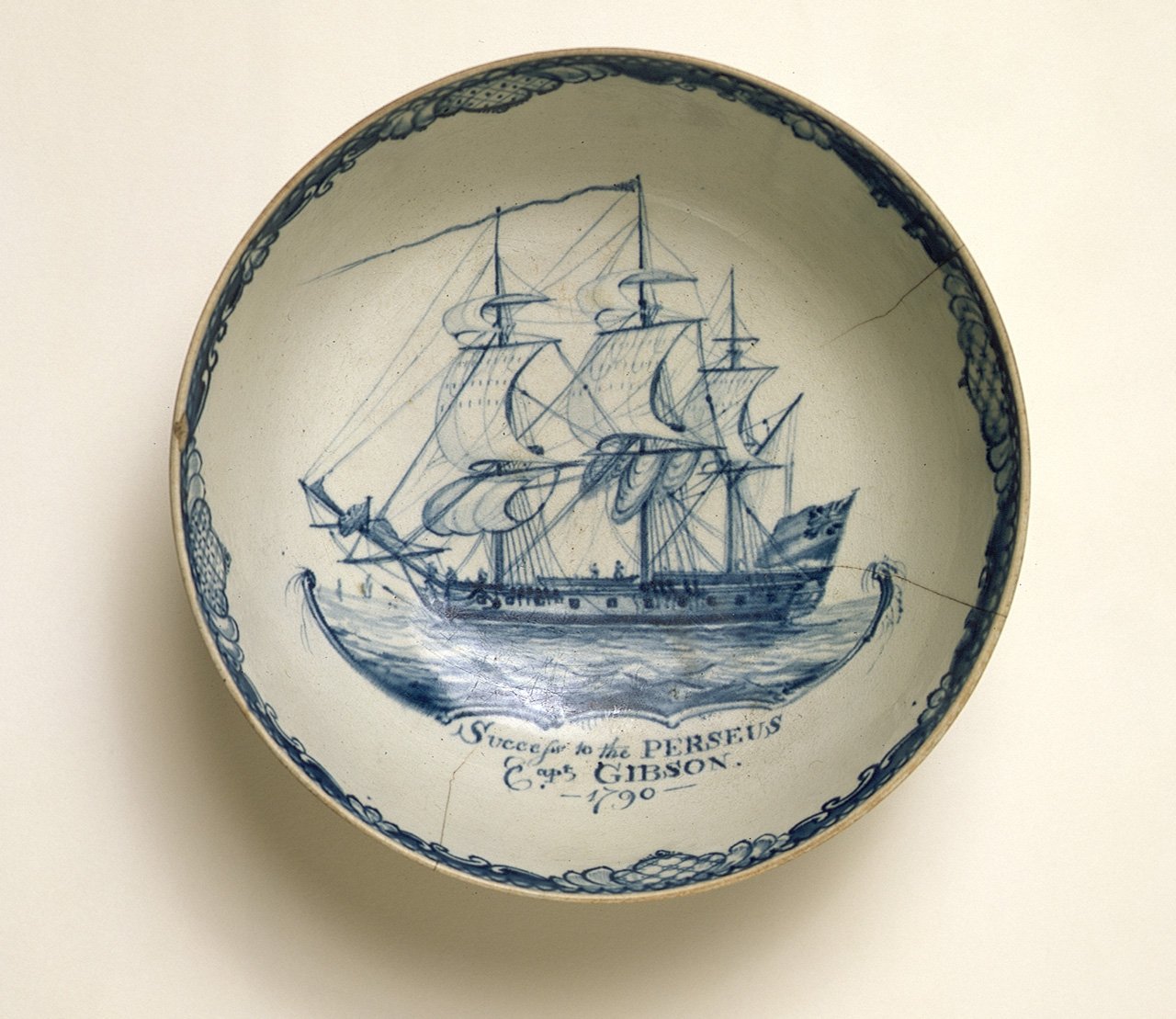
There is little to no historical information available on John Gibson. He was born sometime around 1740 and was posted Captain on 23 December 1782 as commander of the Porcupine (24).His time as commander of Perseus, from 8 May 1787 to 15 March 1791, appears to be uneventful with the only recorded events being refits. As with the time under the command of George Palmer, Perseus appears to have spent this time serving in the Irish Sea and the Channel. At some point in late 1789 or early 1790, Gibson was given or had commissioned a bowl with a hand painted image of Perseus under sail.
Bowl Depicting Perseus Circa 1790

National Maritime Museum, Greenwich, London. AAA4434.
The bowl is notable as it contains a remarkable amount of detail. This represents one of my primary reference points for Perseus. Some notable details that can be seen include:
- The bulwarks on the quarterdeck are built up, but not on the forecastle.
- No armament can be made out on the forecastle (unless that tiny bump between the two people is a carronade), but the quarterdeck could potentially have three gunports (alternatively those marks could simply be smudges).
- No decorations are visible except for the figurehead. Not much detail can be made out of this, but it does appear that the left arm may be extended.
- There are no visible decorations on the quarter galleries or the stern, but it is impossible to definitively say if this represents their absence or just a lack of detail in the painting.
- The traditional lighter band above the wales is visible and appears to be larger than traditionally is visible on most depictions of similar sized RN warships of the period. In particular it is wider than the Marshall painting would suggest the band should be. The line runs above the gun ports as opposed to through them on the Marshall painting.
- The rigging is quite detailed and appears to show most of the principle standing lines as well as some of the running rigging.When compared to the rigging diagram for a 20 gun ship in Steel, there appears to be an extra stay above fore, main and mizzen topgallant stays.
- The ensign is depicted attached to an ensign staff and no boom is visible. The darker colour of the ensign compared to the sails suggests it was a red or blue ensign rather than a white one.
- One boat (possibly a pinnace due to its length) is visible on deck and the small bower can be seen apparently rigged to the cathead, but no sheet anchor is visible.
Gibson does not appear to have had another command after Perseus and died on 30 June 1824 in Somerset.
On the design side of things I had to redo a bunch of my work because I discovered a scaling issue between my different reference plans which resulted in the dimensions being slightly off. So I am still trying to adjust for this. On the research side I am still digging into the knee of the head arrangement and have managed to find at least 6 contemporary examples which likely represent English construction practices. I will do a full post on this subject once I have a firm idea in my head as to what I am going to go with for Perseus.
-
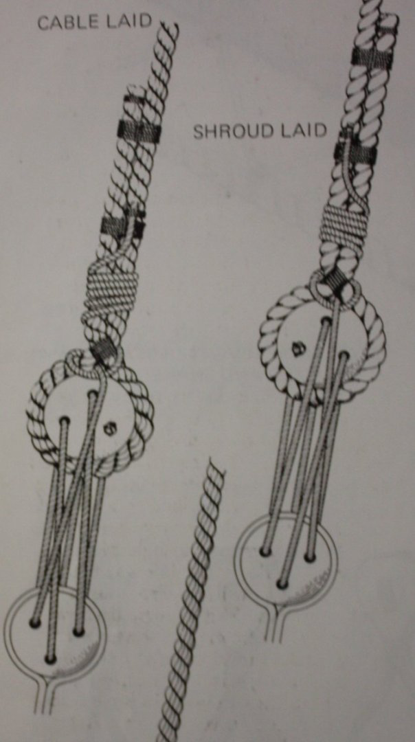
On the button pendants if you look at the diagram of the standing rigging for a 20 gun ship, steel refers to the pendants for the main, and fore topmasts as burton pendants as well as the mizzen.
https://maritime.org/doc/steel/part7.php#pg235
There is nothing clear in the diagram to differentiate them.
-
Fantastic, I love it when you find these fun historical details. For me finding these sort of things is as much as part of the fun as building the model.
- mtaylor, Ryland Craze and Tony Hunt
-
3
-
41 minutes ago, DeMaster76 said:
I'm currently building a Sphinx class ship myself.
Which period are you building her from? As launched or a later date. Many of the sphinx class saw significant changes over their lifetimes, many of which I have documented.
I am always happy to collaborate. My research document where I am compiling all my info is well over 200 pages at this point so if you have some specific questions regarding the ships I may very well have found something interesting.
If you are still in the design phase you might want to check out my first post where I include a link to a transcription of the contract for Perseus and unicorn. I had to make some adjustments from Alex's plans because his drawings did not always line up with it.
- CiscoH, mtaylor and Glen McGuire
-
3
-
What you said of rope coils is true of so many details on a model ship. Most will not notice them. That being said I do think that though people don't consciously notice them they may in the aggregate grasp the higher overall quality of the model for all those extra details.
In any case as you pointed out, you will notice which is really what matters.
Fantastic work.
-
That display is quite the work of art. Your friend is indeed talented.
- FrankWouts and glbarlow
-
2
-
-
42 minutes ago, rmccook said:
The HMS Alert is such a pretty little boat. I really do like it.
Alert is great. You can make something nice out of the box but also there is lots of scope for small improvements. It was my first build (see signature for the build log) and I was very pleased with it.
-
1 hour ago, rmccook said:
Anyone have a link to this post--shockingly, searching "frigate" isn't helpful, but I'm in the same boat as Burgundy, looking for my next kit and loving the idea of a frigate, but interested to hear the reasons I shouldn't.
As Jacques said it is hard to recommend something without knowing your exact skill level. It all depends on how hard your first subject was and how successful you were with it.
If you are keen on a warship here are some suggestions that are smaller and easier than a full frigate:
- Vanguard Models Sherbourne (small cutter)
- Vanguard Models Alert (large cutter)
- Vangard Models Flirt or Speedy (small brig)
Especially as a new entrant to the hobby I find the VM kits are great. They are a little pricier than some other brands, but they have higher quality materials making building easier.
- mtaylor, rmccook, Ryland Craze and 1 other
-
4
-
I like the ideas you have. I was looking at contemporary depictions of Danish frigates and I found this one from the battle of Copenhagen in 1801 at the RMG (I have copied the relevant potion):
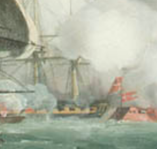
https://www.rmg.co.uk/collections/objects/rmgc-object-12020
You can see the yellow band is actually a bit wider than you have it. It seems to me (a general observation on the many frigate paintings I have looked at) that when the switch from painted decorations to just black and yellow came they tended to make the yellow band wider. You might want to consider bringing the yellow band up to the next molding sand potentially make the molding black. Granted this is a bit later than when your ship launched.
The ship in the painting appears to have built up quarterdeck bulwarks hence the large black band on the top.
I agree with Ronald, less is more. If you are using the maple for below the waterline then I would also use it for the deck as they are both meant to be "whiteish".
-
Good luck. Cutters make great projects. There are a number of sherbourne build logs on MSW you should take a look at to help guide you through the process. You may find that Trial, Alert or Cheerful build logs might also be useful. Lots of collective wisdom to draw on to learn from everyone else’s mistakes.
-
Welcome to MSW
- mtaylor, Keith Black, AJohnson and 1 other
-
4
-
Good job, you will always feel much happier doing something over. If it was bothering you now it will bother you much more in a month. In my experience to produce a good result most tasks (particularly those related to rigging) need to be done at least twice to get them right.
-
I have no knowledge about ancient seafaring practices, but steel gives the ratios for blocks to rope for the late 18th century (https://maritime.org/doc/steel/part5.php#pg153).
-
Log #6: Service History Part IV - James Richard Dacres
James Richard Dacres
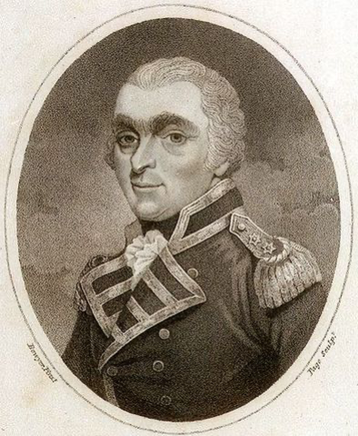
National Maritime Museum, Greenwich, London. PAD3166.
James Richard Dacres was born in February 1749 at Gibraltar, the eldest son of Richard Dacres. He joined the Navy 1762 as a Midshipman aboard the Active (28) and received his promotion to Lieutenant in 1769.
His first command came in 1776 when he was given the schooner Carlton (12) on the strategically important Lake Champlain. Under command of Captain Thomas Pringle, the British force engaged Benedict Arnold’s American flotilla near Valcour Island. During the battle, Dacres was knocked unconscious and command of the Carlton fell to a midshipman named Edward Pellew. In the ensuing battle the American fleet was destroyed with only a few escaping.
Defeat of the American Fleet off Crown Point in Lake Champlain
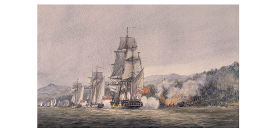
Library and Archives Canada, Acc. No. 1970-188-498 Coverdale Collection of Canadiana.
Despite being knocked unconscious during the battle, Dacres was singled out for praise for his role in the victory and was sent home with dispatches of the victory. There seems to have been some grumbling on the part of a number of officers who took part in the battle that the credit was unduly bestowed on Pringle and Dacres, but this grumbling does not seem to have impacted Dacres’ fortunes as he was given command of the sloop Sylph (18) shortly thereafter.
On the 13th of September, 1780, Dacres was appointed post Captain and given command of Perseus. Where Elphinstone’s log entries exuded energy, Dacres appears to have been a man of less words. Most entries are to the point giving limited detail.After several months of repairs and fitting out, Perseus sailed from the Downs on the morning of the 30th of November 1780 in company with the schooner Racehorse (14) and the cutter Expedition (10). Sailing off Beachy, the three ships encountered a French privateer on the morning of December 1st. The French vessel, the Compté D’Aveaux a brig out of Boulogne, attempted to run, but during the engagement was holed below the waterline and began to sink. Around 40 French sailors were rescued, but the remainder perished along with an officer from the Racehorse who had gone over to take possession of the French ship.
On December 20th, war was declared with the Dutch and shortly thereafter, on the afternoon of the 25th, Perseus encountered and made a prize of the Dutch snow Vriendschap sailing south of Portsmouth. It seems that the Dutch ship in question had not received word that war had been declared as she was bound for London carrying goods belonging to British merchants.
Dacres' luck continued as on the 3rd of January he encountered a Dutch East Indiaman not far from where he had captured the snow. This proved to be a very valuable prize as she was loaded with silver and gold coins as well as other valuable goods.
Map of Significant Events for Dacres’ Command of Perseus
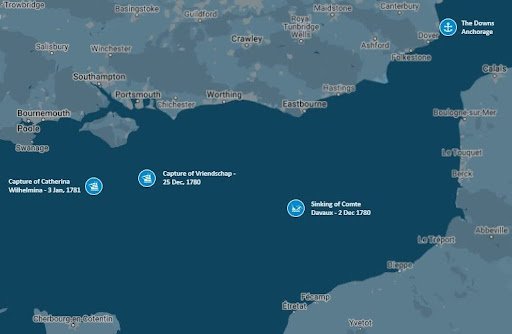
Map produced by me based on log entries from the Journal of HMS Perseus.
The rest of Dacres' time in command of Perseus appears to have been somewhat uneventful. Much of his time was employed escorting convoys and with the exception of a storm which nearly grounded the ship on the sand bars in the Downs, there are no significant events to note.
Perseus was paid off in March of 1782 and Dacres was given command of the Orpheus (32). Dacres went through a long period of unemployment after the peace of 1783, but in 1793 when war once again broke out with France, he resumed active service. He went on to have a successful career reaching the rank of Vice Admiral. He passed away on January 6, 1810 after falling off of a horse at the age of 60.
On the design side of things I have simplified the design a bit to show less of the lower deck and to make the lower frames a little thicker. You can see below the current state of affairs.
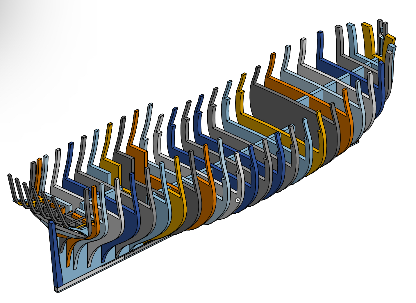
One thing I am wrestling through at the moment is the design of the various parts that make up the head. I am wondering if anyone has any contemporary documents or models you can think of which show the construction of the head broken into its various components.
Examples I have already found:
- 18th Century Shipbuilding by Blaise Olliver (1737)
- Bellona Model (1760) https://www.rmg.co.uk/collections/objects/rmgc-object-66464
-
Egmont Model (1768)https://www.rmg.co.uk/collections/objects/rmgc-object-66105 EDIT: I just realized this is actually a model made in 1980 so not actually helpful even though it is a beautiful model.
- JacquesCousteau, AON, CiscoH and 9 others
-
12
-
Found another one, this one a french ship held by the science museum in London:
- mtaylor and thibaultron
-
1
-
 1
1


HM Cutter Trial 1790 by AJohnson - FINISHED - Vanguard Models - 1:64th
in - Kit build logs for subjects built from 1751 - 1800
Posted
Fantastic job Andrew. The whole thing comes together really well.