
Thukydides
-
Posts
1,272 -
Joined
-
Last visited
Content Type
Profiles
Forums
Gallery
Events
Posts posted by Thukydides
-
-
-
I have been digging around the forums and in my searches have found inconclusive answers to this question so I figured I would pose it to see if anyone is able to clarify this for me. This is what my general understanding of naming is:
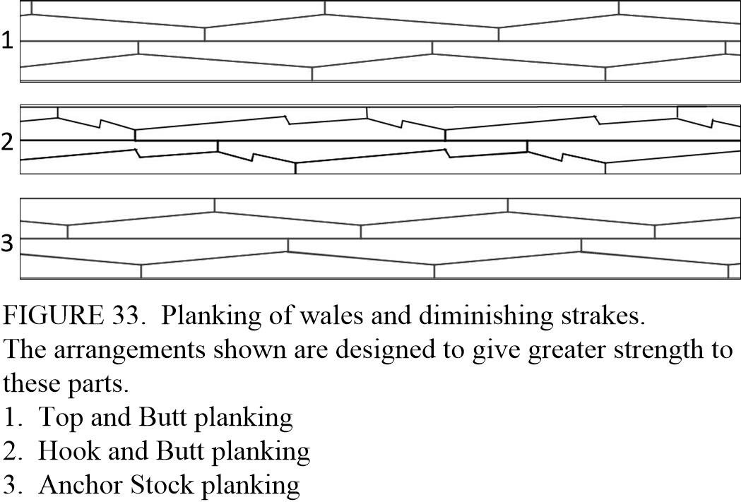
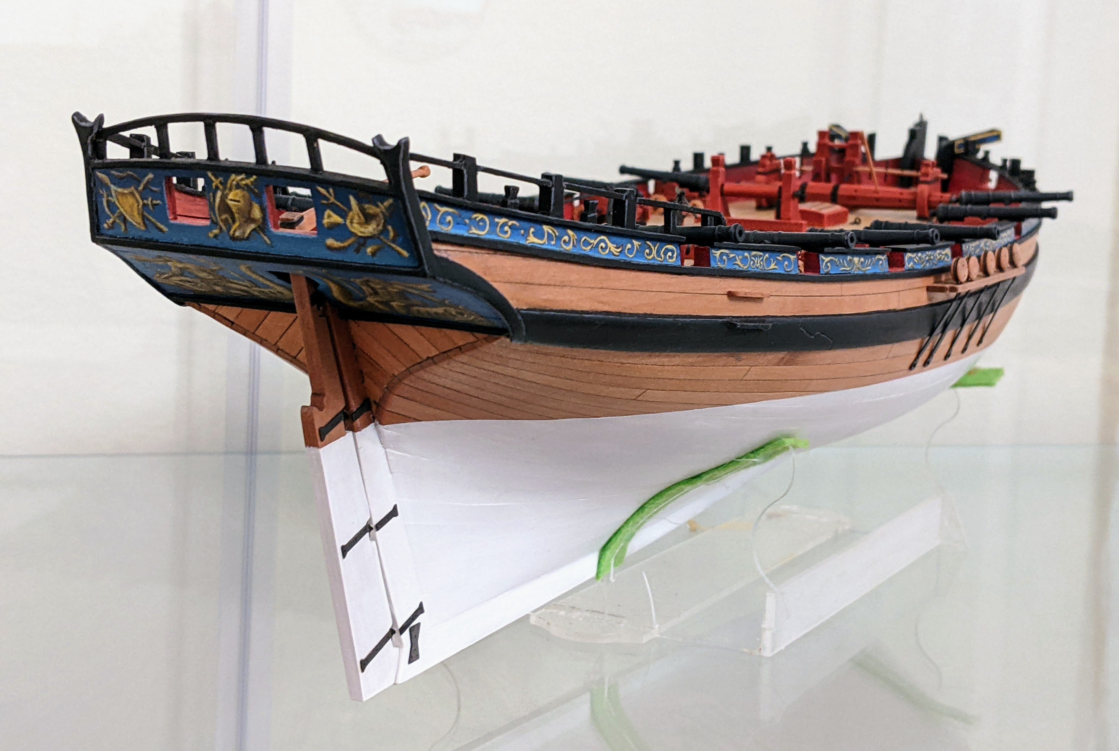
My question is what would the joint in the below plan be called? They have the scarfs of hook and butt, but appear to be simply two scarfed strakes. Could this also be called hook and butt? For clarification these two strakes show the upper deck clamps for Sphinx 1775.

-
Congrats, she looks fantastic.
- Canute and Keith Black
-
 2
2
-
Those oars look really nice. Also as usual I learned something. I always appreciate that you take the time to explain the why not just the what.
- Ryland Craze and Blue Ensign
-
1
-
 1
1
-
4 minutes ago, palmerit said:
Not sure what’s the best way to sand pe if (and when) I leave a sharp bit of the “sprue” on the part. Maybe a file works best?
I use mini files. If you look at my alert log I show some examples of this. In general I find PE often looks out of scale and so you need to file it a bit to get it to look right.
- palmerit, AJohnson and Ryland Craze
-
3
-
Log #4: Service History Part III - George Keith Elphinstone Continued
From late 1776 until late 1779 and the siege of Charleston, Elphinstone continued cruising up and down the North American coast taking prizes at a remarkable rate. One of his most prolific periods was between September 1776 and and September 1777 when he captured at least 14 different prizes ranging from privateers to merchants.
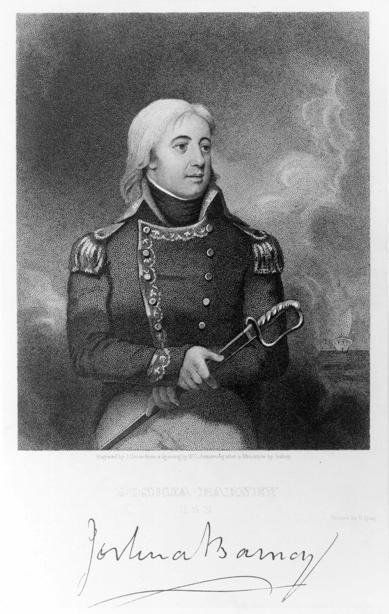
In January of 1777, Elphinstone and the Perseus captured the snow Thomas, a British ship which had recently been captured by the Continental brig Andrew Doria. This event is notable as the American prize officer in charge of the Snow, Lieutenant Joshua Barney, later had a memoir written which recounted the events providing some insight into Elphinstone’s character.
Due to the limited number of crew available, Barney convinced a number of the prisoners to help make up the complement of his crew. A few days later a British warship, the Perseus, was seen on the horizon and it was at this point the prisoners became mutinous and refused to assist in setting sails until Barney shot one of them through the shoulder. However, the delay allowed the Perseus to close the distance and the Thomas was boarded and captured.
Upon being transferred over to the Perseus, the sailor who had been shot by Barney complained to Elphinstone regarding Barney’s actions. Elphinstone, without bothering to even enquire of Barney as to his version of events, chastised the sailor and “declared that the latter had done no more than he would himself have done in a similar situation.”
Joshua Barney
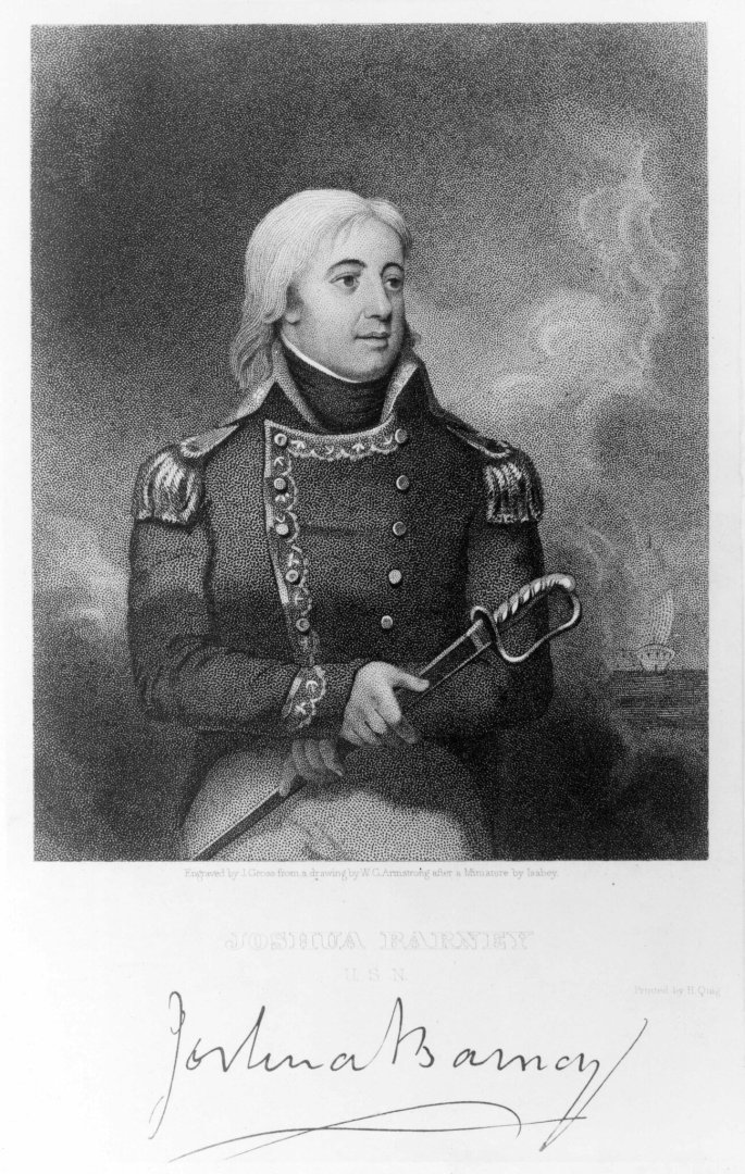
National Museum of the United States Navy, NH 56818
This problem of desertion and insubordination appears to have been quite common for both sides of the conflict. Later in the same year, 10 men who had previously been in the service of the Continental Forces deserted the Perseus taking with them an 8 oared cutter. Despite Elphinstone’s attempts to capture them, they made it to shore at Annapolis and were welcomed by Major John Fulford who requested in a letter to his superior, Governor Thomas Johnson, if he could keep the boat and pay the deserters for it.
Elphinstone’s most significant prize of his North American career was the capture of the 20 gun French ship La Therèse in November 1779 off Cape Charles. The La Therèse proved a difficult opponent and it took 40 minutes of action in which time she “did considerable damage to the masts, sails, and rigging of the Perseus before she struck.”
In late 1779, the decision was made that the time had come for the British to capture the port of Charleston. A barrier to the northward progression of British success in Florida and Georgia, the city was protected from the sea by a sand bar and heavily fortified islands guarding the harbor.
Alonzo Chappel, The Siege of Charleston
.png.c1c5f8da9629457a3474b31c6c121600.png)
Anne S.K. Brown Military Collection. Brown Digital Repository. Brown University Library.Elphinstone was dispatched in advance of the campaign to procure galleys and transports for the assault as well as procuring the necessary supplies to support the seaborne invasion force. Once the attack began in earnest, Elphinstone lead a force of four hundred and fifty seamen ashore to support the attack and serve as the line of communication between the army and the fleet.
The city fell on the 12th of May and as a reward for his efforts, Elphinstone and the Perseus were selected to carry Sir Andrew Hammond with the dispatches announcing the fall of Charleston back to England. Perseus was paid off on the 17th of July, 1780 and Elphinstone was given command of Warwick (50).
Elphinstone, who is perhaps best known in modern times for his appearance in the Jack Aubry novels as Lord Keith, went on to have a very successful career becoming one of the more decorated and famous naval officers of the Napoleonic period. Notably, it was under his command that Napoleon was transferred from the Bellerophon to the Northumberland for his exile to St. Helena in 1815. He retired having reached the rank of Admiral and passed away on the 10th March 1823 in Tulliallan Castle in Scotland.
- Arthur Goulart, AJohnson, rcweir and 9 others
-
12
-
-
-
Another wonderful SIB. I think it is you basing that really sets it apart. I love the way the whole thing is integrated together.
- FriedClams, Glen McGuire, Keith Black and 2 others
-
4
-
1
-
9 hours ago, Blue Ensign said:
One of the most striking features of a Longboat is the Windlass, used for anchor handling.
Fantastic work BE.
I do have a question on the windlass. Were these on all longboats or only the larger ones?
-
-
36 minutes ago, brunnels said:
That looks great, what do you use to glue PE that small without tons of excess glue?
Unfortunately I don’t have much wisdom to offer here, this is my first time using this small PE. I just used thin super glue and it didn’t work out as well as I would have liked. If you look closely you will see in a few of the joints there is indeed a bunch of excess glue. The main problem I found was getting it right the first time. If you have to redo the joint several times there is inevitably a buildup.
- mtaylor, Canute and Old Collingwood
-
3
-
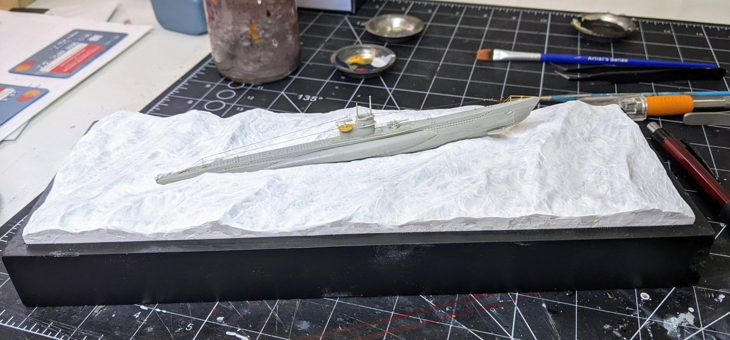
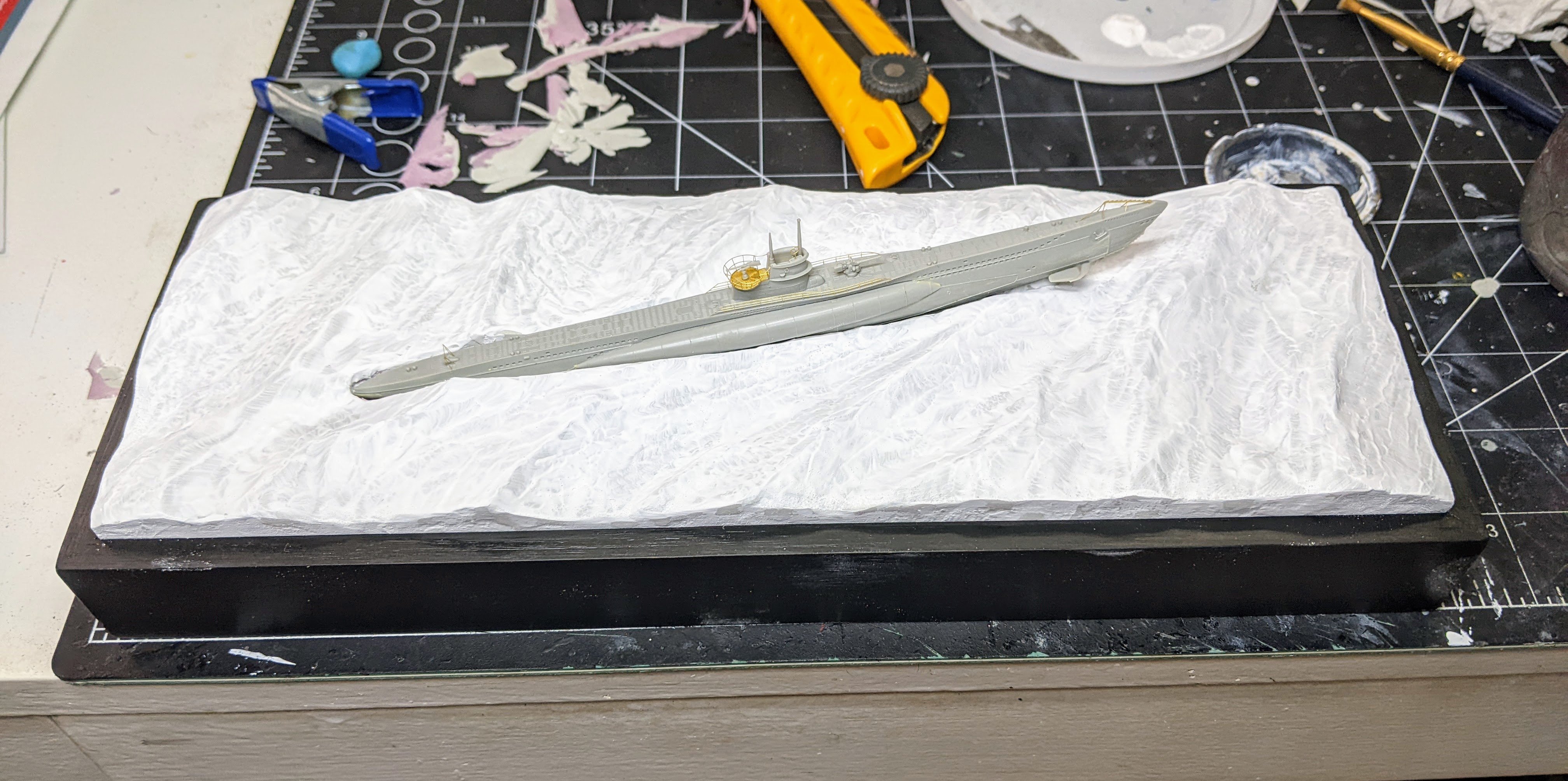
Final update before painting. I went back in and did some more touchups with gesso accenting waves and fixing minor issues I didn’t catch with the first pass. I also added the cables using 10/0 fly tying thread and then added small mod podge droplets with a toothpick to simulate the connectors on them.
-
Looking really good, water is hard to do right.
- Glen McGuire, Canute, Keith Black and 2 others
-
4
-
1
-
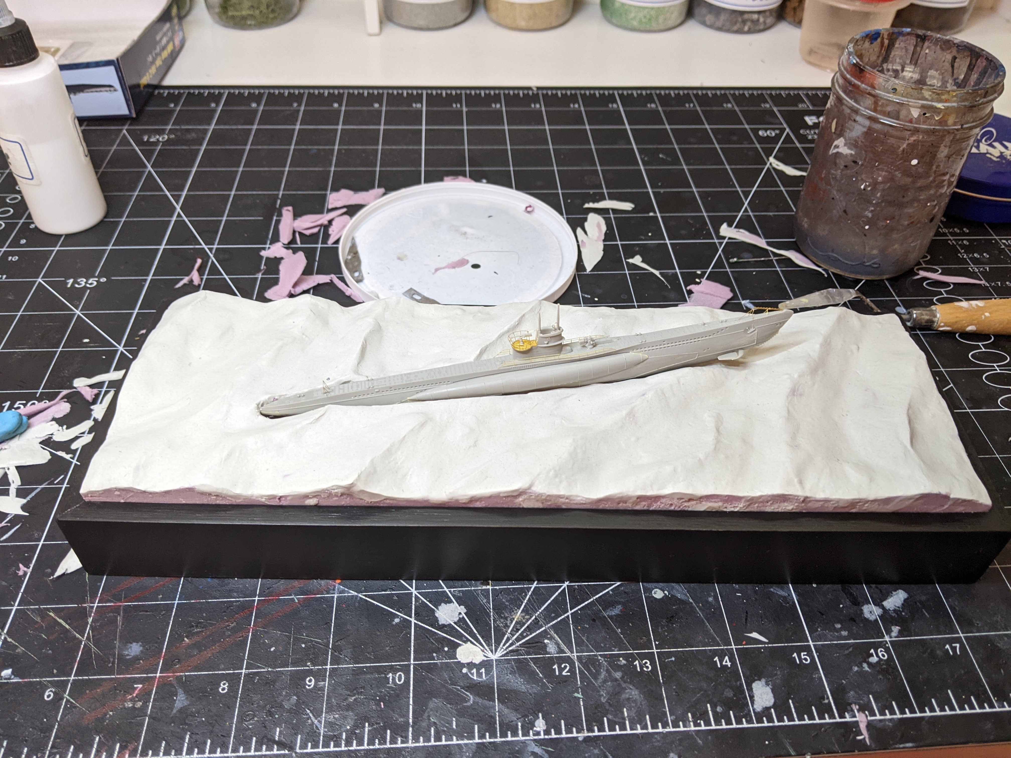
@mikegr's suggestion worked really well. I was able to cover up all of the seams and also add some texture to simulate the smaller waves. Next up I need to attach the cables and then on to painting.
-
-
2 hours ago, mikegr said:
Maybe use some thick gesso layers instead of gel to smoothen up things. Its really easy to work with
Good idea, I may try that and as it dries I should be able to texture it a bit. I had planned to put another thin layer of putty, but that might be easier. Thanks for the suggestion.
- mikegr, mtaylor, Old Collingwood and 2 others
-
5
-
Log #3: Service History Part II - George Keith Elphinstone
A lot of work is going on in the background that is not yet ready to share, but to avoid this log going too dead I am going to keep dribbling out some of what I have already gotten done. We are going to work our way through the service life of Perseus starting today with her first and most famous commander George Keith Elphinstone. As I have a lot of info on his time in command of Perseus I am going to break this up into two parts.
I should also note that all of these posts are lifted from the research document I am working on which I plan to release on MSW whenever it is finished (likely not for a while yet). That document will contain more detail as well as extensive notes linking almost every assertion made back to primary sources. If in the meantime anything I am talking about peaks your interest I am more than happy so share relevant sections of the draft for feedback / to aid you in your own research.
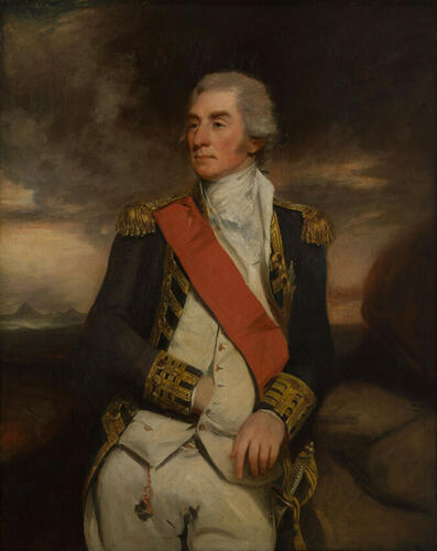
A painting of Elphinstone in 1799, Royal Collection Trust. RCIN 400990.
George Keith Elphinstone was born on the 7th of January 1746 in the county of Stirling in central Scotland. At the age of fifteen he joined the navy as a midshipman on board the Gosport (44) under Captain John Jervis. With the start of the peace in 1763 Elphinstone found himself transferred from ship to ship in search of a berth. There were few opportunities for midshipmen in this period and so the young Elphinstone resigned the navy in favor of an opportunity with the East India Company on board a vessel commanded by his elder brother William.
Elphinstone returned from his eastern expedition sometime in early 1771 and with war looming on the horizon he was shortly thereafter reinstated in the Royal Navy with credit given for the experience gained in his time with the East India Company. On the 21st of May, 1771 he was appointed 2nd Lieutenant of the Trident (64) part of the Mediterranean fleet of Admiral Sir Peter Dennis keeping an eye on French and Spanish ports.
He received his first command on the 18th of September 1772 with the sloop Scorpion (14). He spent several years cruising the Mediterranean until in the summer of 1774, Scorpion was ordered back to England.
Elphinstone was given command of the Romney (50) on the 11th of March 1775 with his promotion to post Captain coming on May 11th. However, his time on Romney was to be short lived. After returning from escorting a convoy to North America, in March 1776, Elphinstone was appointed to command the newly constructed Perseus (20).

The Romney in action later in her career, National Maritime Museum, Greenwich, London. PAF5826.
Elphinstone by all accounts appears to have been an active and competent commander. In his writing you get a sense of his forceful personality and the energy with which he carried out his responsibilities. Perseus had been built by contract and Elphinstone was not pleased with her status upon first inspecting her. There are a number of letters in which he makes a flurry of requests for surveys to fix defects and supplies for the fitting out of the ship.
Perseus departed Spithead in July 1776 with a convoy of vessels bound for North America. Perseus was evidently the only Man of War present and a number of the vessels in her charge went missing. Elphinstone recounted many of these difficulties in his explanatory letter to Vice Admiral Howe, the British Naval Commander for the North American Theatre, on November 6, 1776.
It is beyond a doubt that I chased different Ships of the Convoy the whole day, fired a great many Shot at the offenders, rebuked the Masters &c. and with difficulty once more collected them. On the 18th I parted from the Lark and the Snow under her Convoy, consequently 17 remained under charge of the Perseus, not one of which was lost before our being driven on the Banks of Newfoundland, where we were dispersed by Gales of Wind and thick fogs.
(Elphinstone, Nov 1776)It is evident that Elphinstone had a talent for taking prizes. There are Admiralty prize records for at least 24 different prizes captured from 1776 to 1780. His first prize was taken before he even reached his station. While escorting the aforementioned convoy, he took the American Schooner Viper. This incident also illustrates the energy with which he did everything. The Captain’s log for the 26th of September 1776 describes how with great difficulty they managed to get one of the 9-pdrs. up to the forecastle to fire on the schooner as they pursued her.
Once in North America Elphinstone was placed in a squadron of 4 ships under the command of Andrew Snape Hamond of the Roebuck.
There was a brief period in 1776 when Elphinstone was transferred to the Pearl (32) and command of Perseus was given to Captain Hon. Charles Phipps. The transfers were ordered by Vice-Admiral James Young while the squadron was refitting at Antigua following the death of the Pearl’s captain, but upon them regaining their station in North America, the appointments were reversed by Vice-Admiral Lord Howe, as he considered the appointment should have only been made by him.
-
2 hours ago, AON said:
I know I'm standing back quite a distance but it looks damn good from Ontario! 🤣
Will you be using any of the techniques shown at one of te NRG Saturday Zoom workshops. They have a video on the website if you want a refresher.
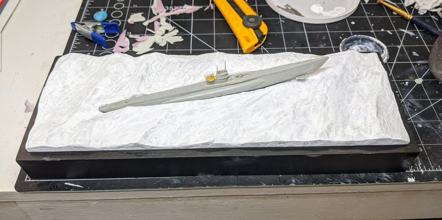
The issue is not the general shape. I am pretty happy for that as a first try, it is seam lines where I put putty on top of other putty which really doesn't look like water. You can't see it easily because everything is white, but once I start painting they will be very visible.
As to the techniques the answer is some of them. I have not yet seen the workshop, but I am familiar with his method as I followed his build log for Camilla. Some of his techniques are pretty universally used, but some of them are more specific to his scale. Where I am at 1:350 it will change some things. I plan to go back and watch it before I actually start doing any painting to get some ideas, but mostly I am following techniques from this youtube channel:
-
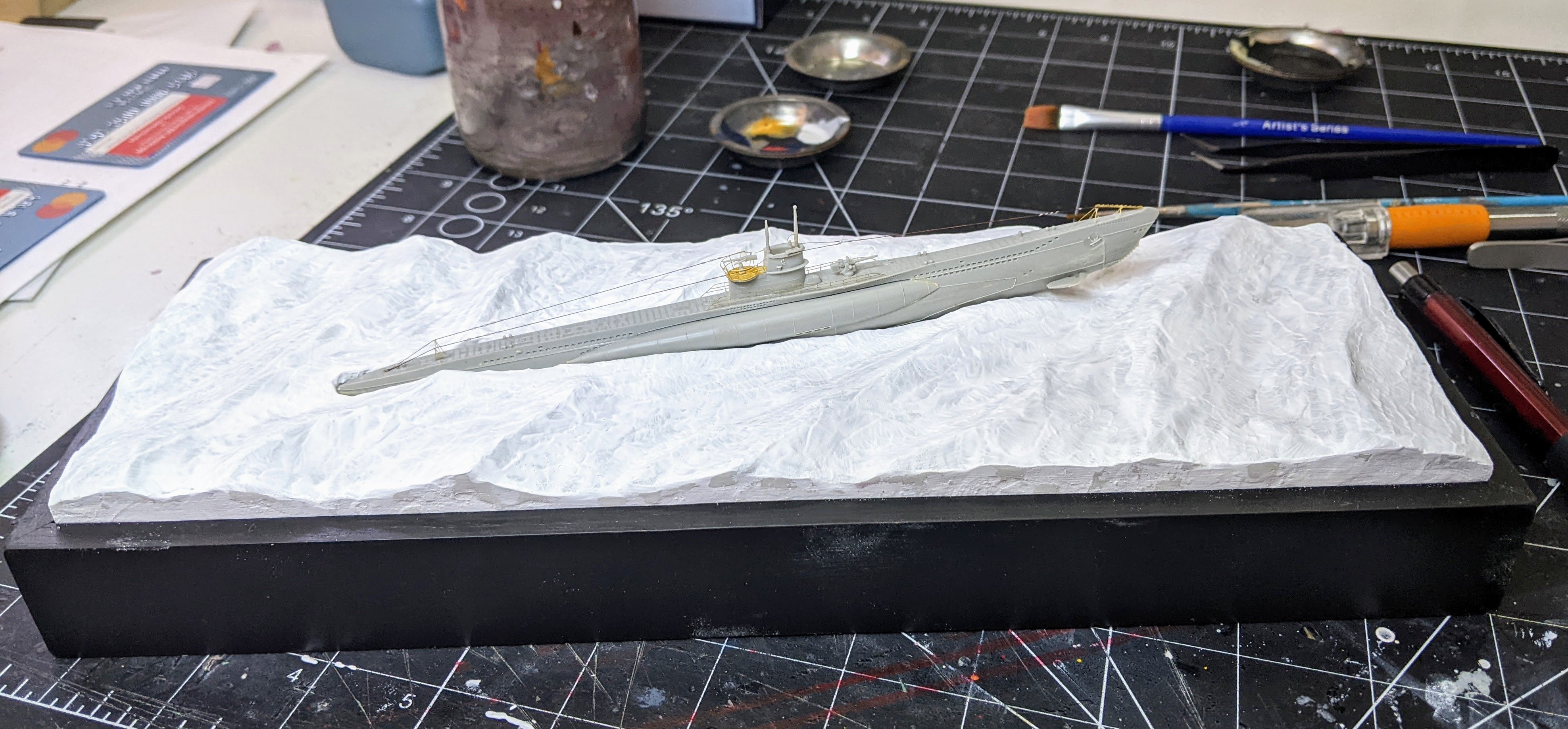
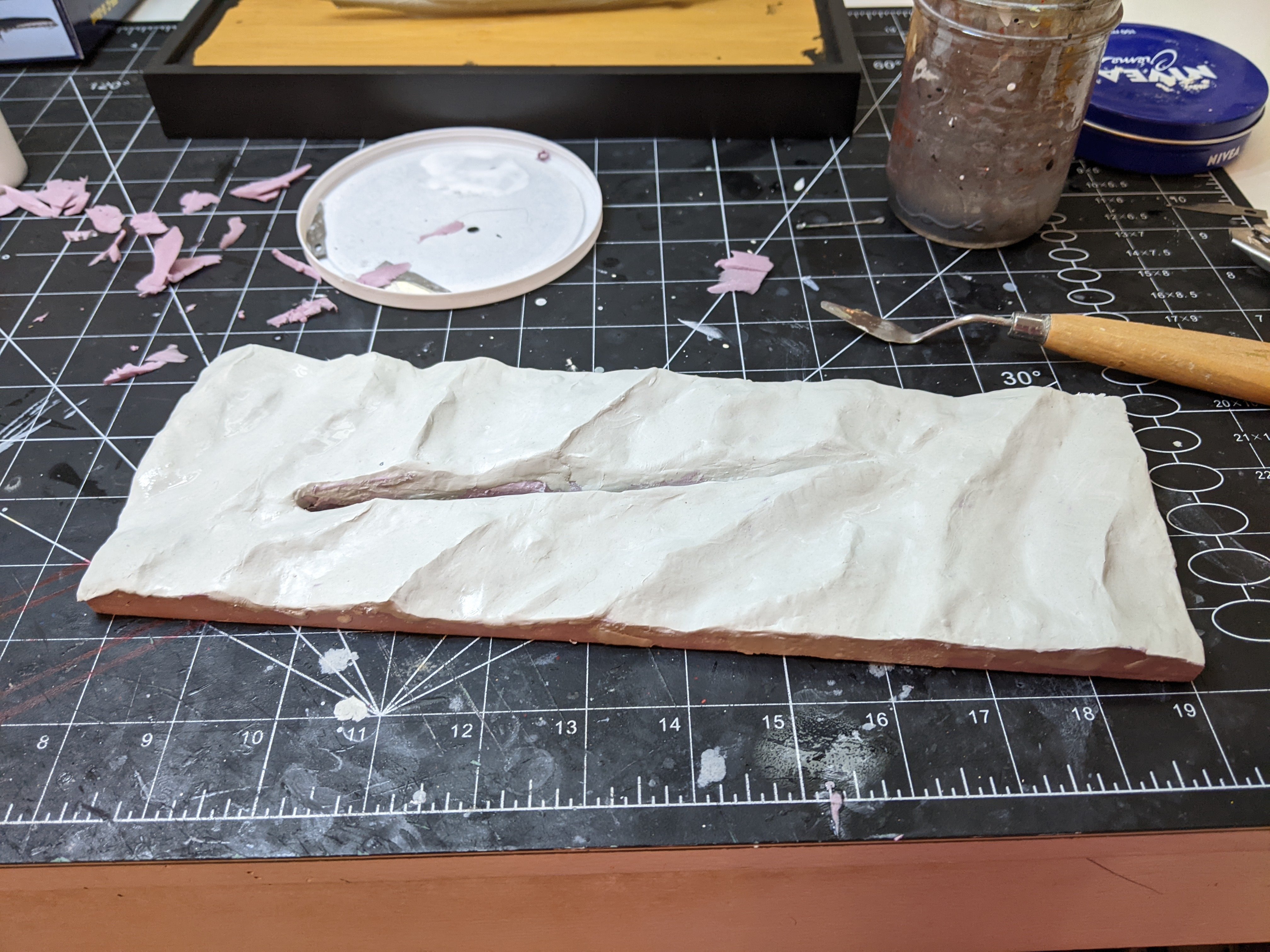
Work is progressing briskly. The base of the seascape is now covered in epoxy putty.
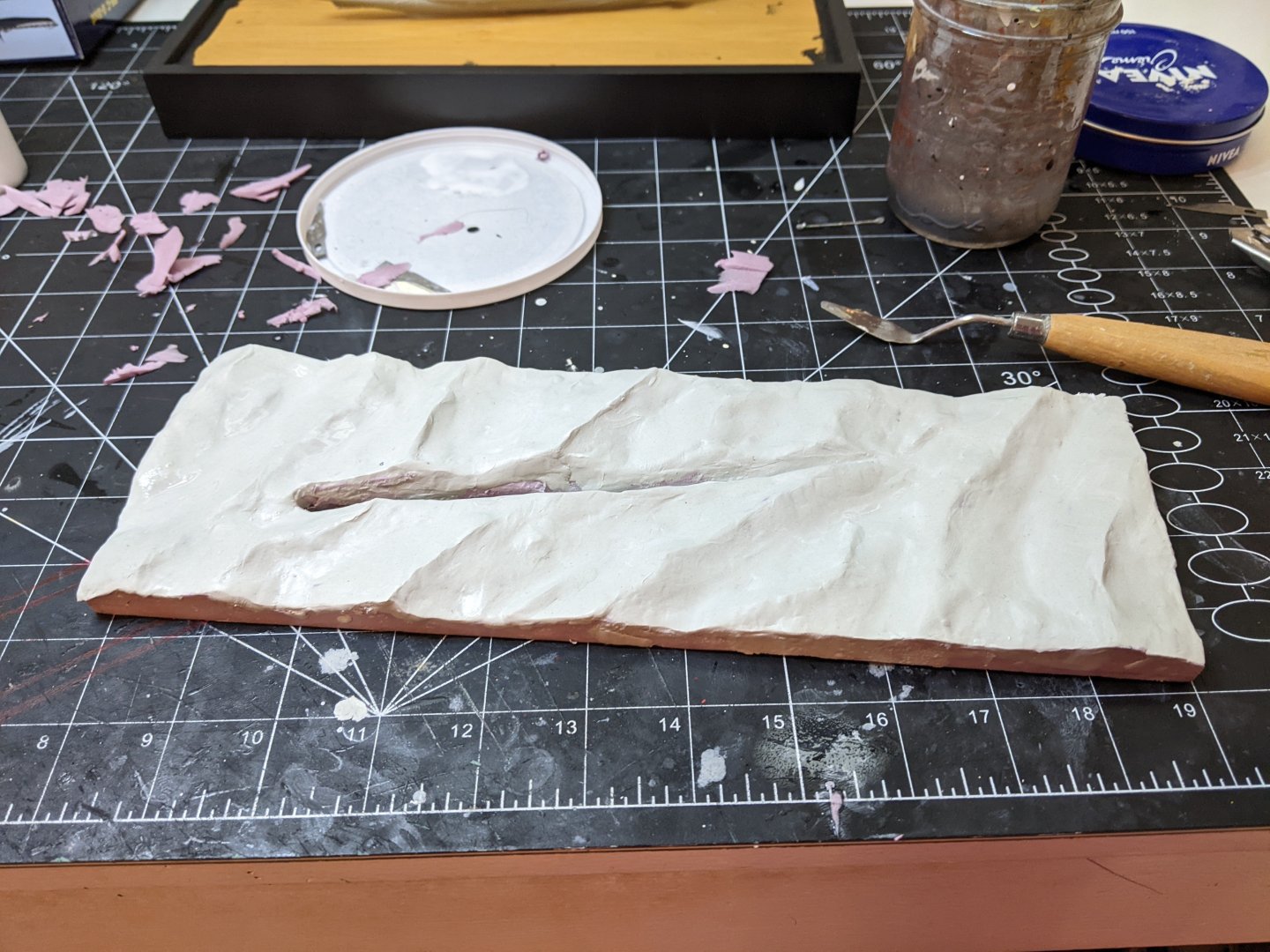
This did not turn out exactly how I was hoping and I had issues shaping the smaller ripples in the water. My plan for texturing the surface didn’t work and I am going to have to come up with a new plan, probably involving building up gloss medium or something like that. However the other issue is the surface is not as smooth as I would like for this, I am going to have to go in with some extra putty to smooth up some of the seams and unwaterlike shapes.
Here is the current state of things after I cut off the overflow on the edges and trimmed the hole to allow the model it sit in it properly.

-
-
In all likelihood I would say if the masking tape is pulling it up then the splinters were already there waiting for something to pull them up.
That is very frustrating. Maybe try sticking some tape to the uncut piece before cutting it to see if anything comes up. Then if not you can go ahead with cutting.
-
17 minutes ago, AON said:
... and again I am learning something new!
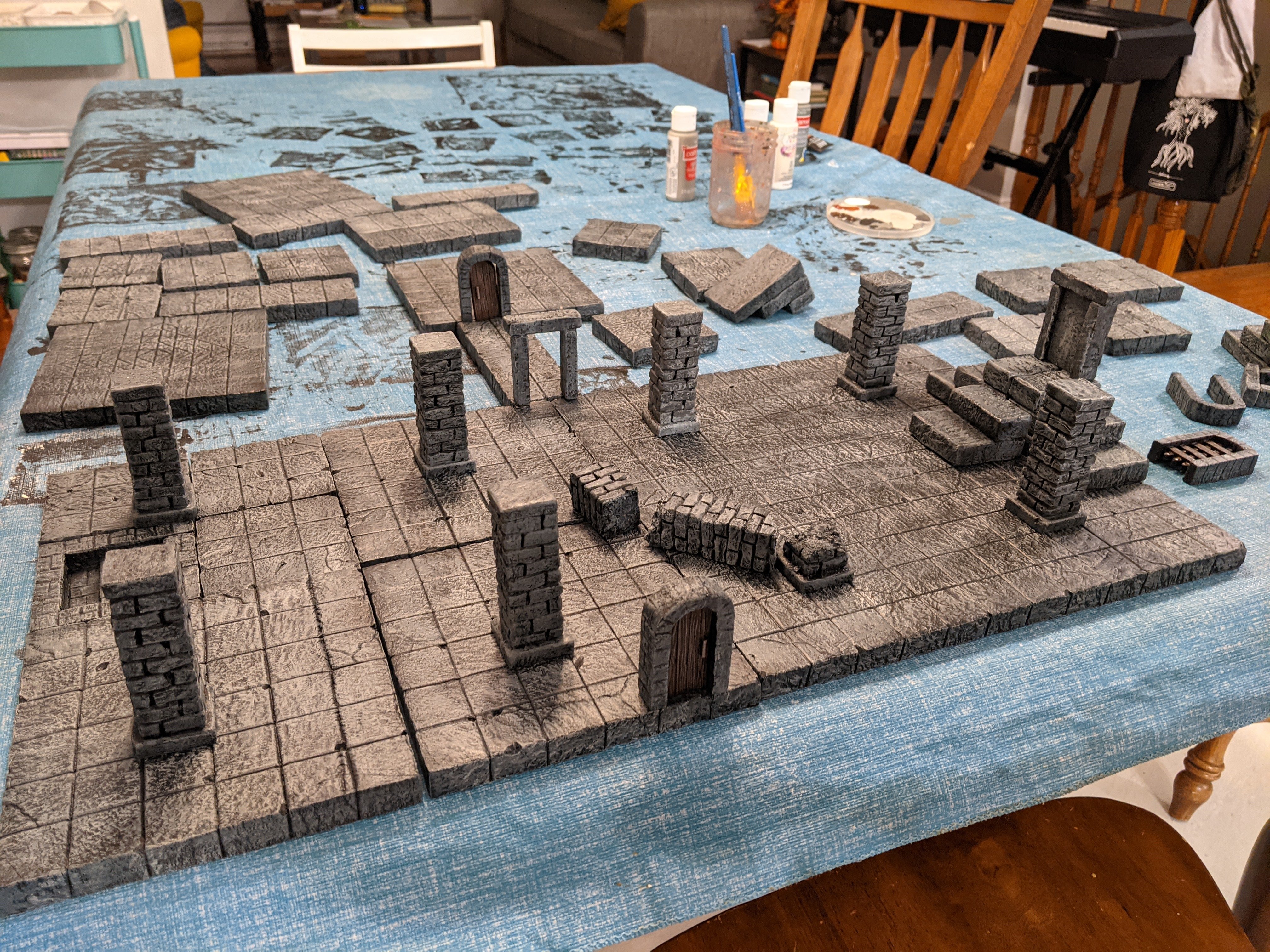
I assume you mean the foam. It is great stuff. It is light and strong, but you can imprint shapes into it. I make all sorts of hobby stuff out of it. And if you have a hot wire cutter (I don't) you can get really crazy with it. All of the terrain below is made out of the foam.

-
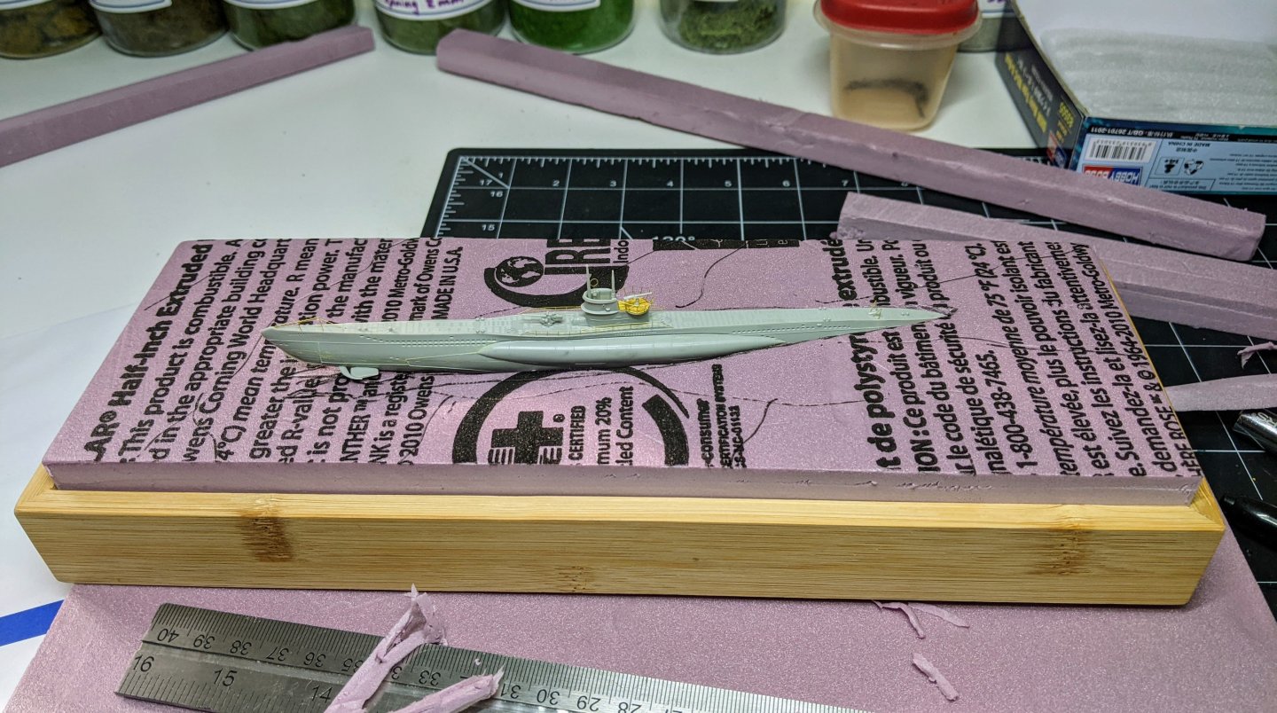
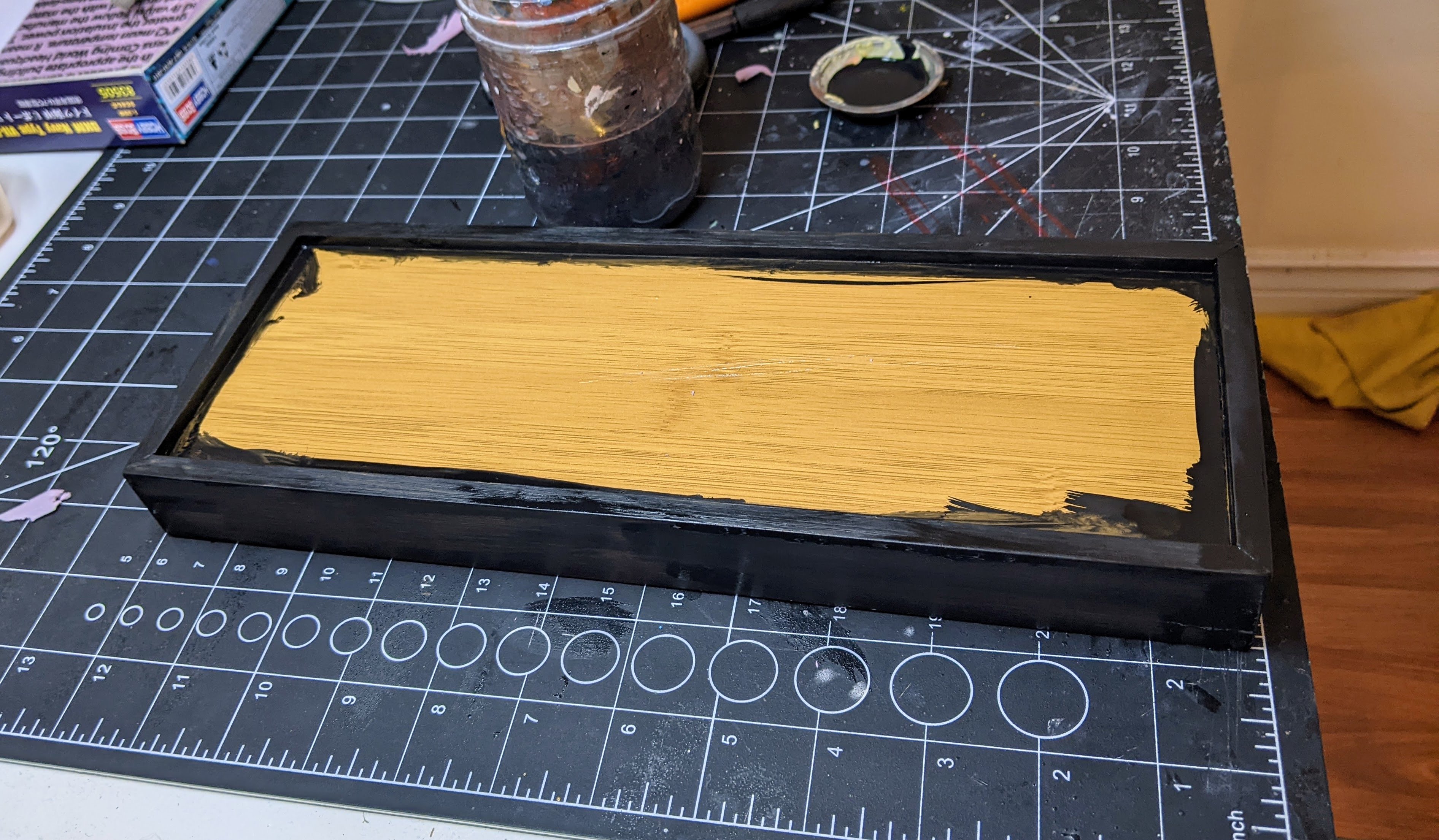
With the model assembled it is time to turn my attention to the base. I found a bamboo tray at dollarama which was about the right size for the base. I flipped it over and used the bottom which had a lip and cut a piece of pink insulation foam to fit. I roughly positioned the model on it and cut out the hole for it to sit in.
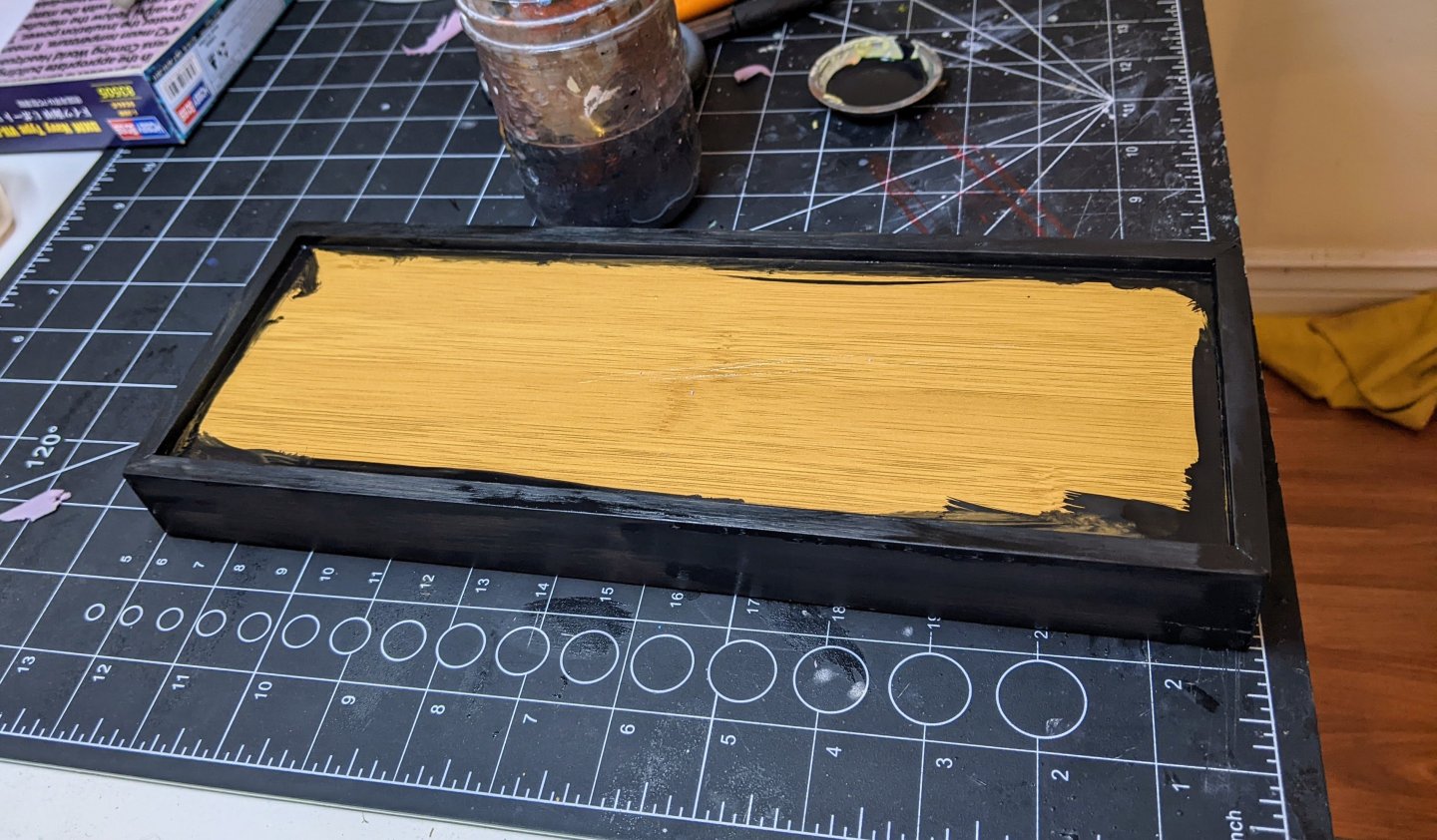
Next up I painted the base. This took many layers with sanding in between. Here is what it looked like after the first coat of primer.
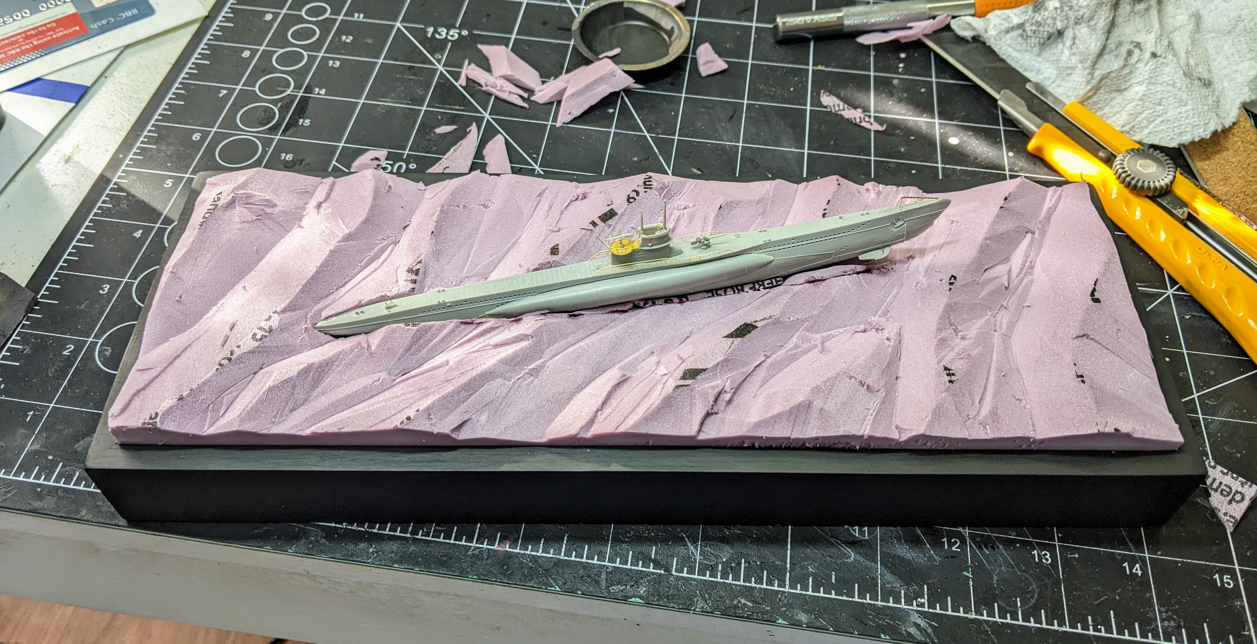
Then it was time to figure out the rough shape of the waves. This involved a lot of reference pictures as I have never done this before. This is only the base for them, the will be refined more in the next step.

You can see in the picture how I inserted back in some small strips of foam as I adjusted the position of everything. Next up the waves need to be refined a bit more.
- NavyShooter, rcweir, Ian_Grant and 9 others
-
12


Some silkspan tips
in Masting, rigging and sails
Posted
Those sails look fantastic Andrew, I really like the method you came up with. They really do give a lot of visual interest to the sails.