
Thukydides
-
Posts
1,268 -
Joined
-
Last visited
Content Type
Profiles
Forums
Gallery
Events
Posts posted by Thukydides
-
-
Welcome to MSW, what kit are you going to be building?
- mtaylor, Arnall, Ryland Craze and 1 other
-
 4
4
-
That is some very precise work. Well done.
- Baker, Siggi52, Paul Le Wol and 1 other
-
4
-
The double thimble vs just a single one, is not something I have seen anyone give a plausible explanation for, maybe because they are stronger?
The thing is even if I think 3 is most likely, it is very plausible that the orientation could be reversed (thimble below the pomillion), or alternatively the breaching was wrapped around the pomillion and then passed through the thimbles.
I have done a lot of looking through the background of maritime paintings and the problem is there are very few depictions of detailed deck scenes prior to the Napoleonic era so almost all the examples I have found are of Bloomfields with the ring as part of the cannon. The only two good examples from earlier periods that I have found appear to show a c**t splice as the means of securing the gun, though they also seem to have the tackles wrapped around the pomillion too.
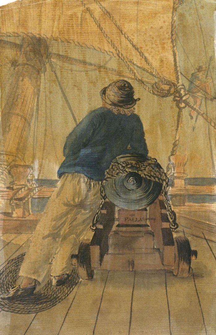
https://www.rmg.co.uk/collections/objects/rmgc-object-200784
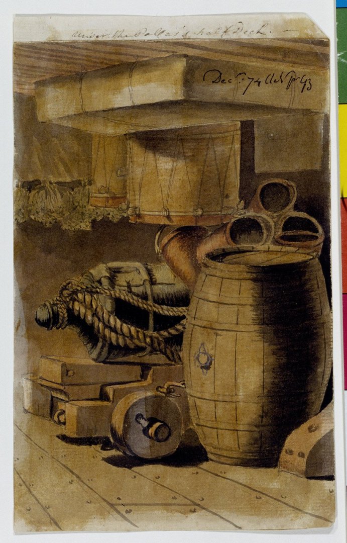
https://www.rmg.co.uk/collections/objects/rmgc-object-200785
-
The only issue with that interpretation is the thimble is strapped to the pommillion.
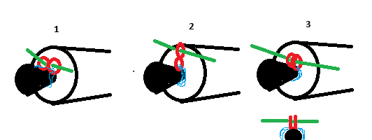
My guess is one of the options below (I feel the third is the most likely, but I have no evidence for this). Not obviously not to scale, just to give you the idea. Red is the thimble, green the breaching and blue the strap. I have included an alternate view of 3 below it looking straight on to clarify it.
1) Figure 8 shape lying flat against the breach strapped to the pomillion. The breaching is reaved through both loops.
2) Figure 8 shape with the bottom loop strapped to the pomillion and the breaching reaved through the upper loop.
3) A bent over figure 8 such that the thimbles are next to each other. A strap is run through both to strap it them to the pomillion. The breaching is reaved through them both. The reason this seems the most likely to me is that it sort of resembles the later loops that were cast on to the guns which makes that progression seem natural.
- Dr PR, cotrecerf and thibaultron
-
3
-
Welcome to MSW
- Keith Black and mtaylor
-
2
-
1 hour ago, Lieste said:
The double thimble sounds like a modification to the seized breeching at the breeching rings paased through the side. Each end of the breeching, seized to a 'thimble and hook' in the bight, can then be detached at will, rather than being reeved through the breeching loop after the seizing is unpicked. The gun and carriage can then be shifted without removing the breeching from it. (looking at the definition of a 'Gripe' and extending it to a 'double thimble', rather than dead-eye and thimble)
The earlier Contsplice could of course be pulled from the gun when needed, allowit it to be shifted, but the breeching, seized to the side would need to be shifted also, or substituted in the new place.
A slightly later modification to the breeching loop allows it to be interrupted with a shackle to close the gap to restrain the breeching.
If this is correct, then the contsplice is still needed for non-looped ordnance, with the double thimble being a convenience for looped guns which don't have a shackle opening, and more generally for ease of shifting or striking/removal of guns.That is an interesting interpretation that I had never considered. The issue is (maybe I am misunderstanding you) is that many of the references refer to the double thimble as relating to the neck of the button.
Page 383 in Caruana's Volume II of The History of British Sea Ordnance goes into a lot of detail. A short synopsis --- Wrought iron double thimbles were attached to the neck of the button. This is documented in the first edition of Falconer's Marine Dictionary (T. Cadell, London, 1769) where it is stated that the middle of the breeching is seized to the thimble of the pommillion. The so-called Burney edition of Falconer, published by Cadell in 1815 is more specific but obviously very out of date, stating that the breeching is fixed by reeving it through a thimble strapped upon the cascabel. Long before 1815, the ring was cast as part of the barrel.
Caruana also refers to these thimbles as an alternative to the c**t splice. However, to this point I have not been able to determine what these thimbles even looked like, let alone how specifically they were attached.
I have often wondered if they were like a figure 8 where one loop was seized to the button and the other loop allowed the breeching to just pass through (a bit like a removable one of the loops that were introduced later with the Bloomfields). My issue with this interpretation is that I question if it could withstand the forces on it as the cannon recoiled.
-
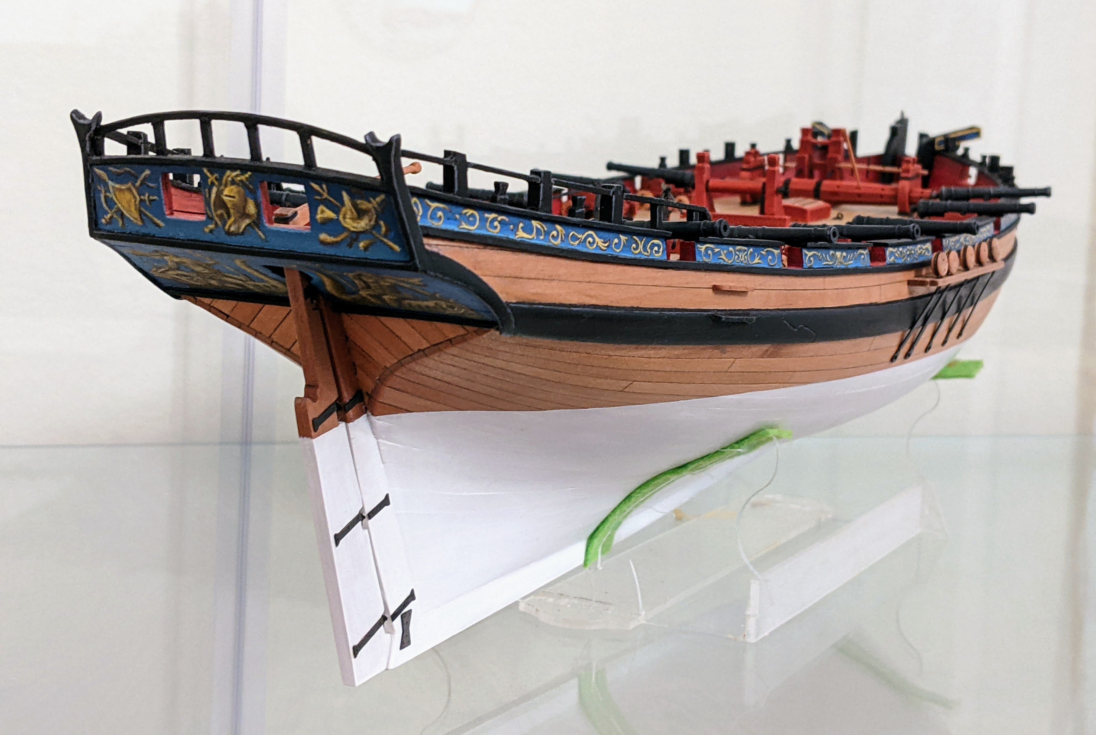
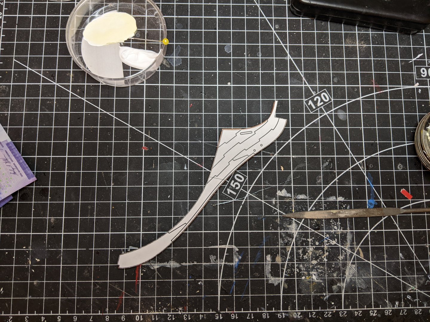
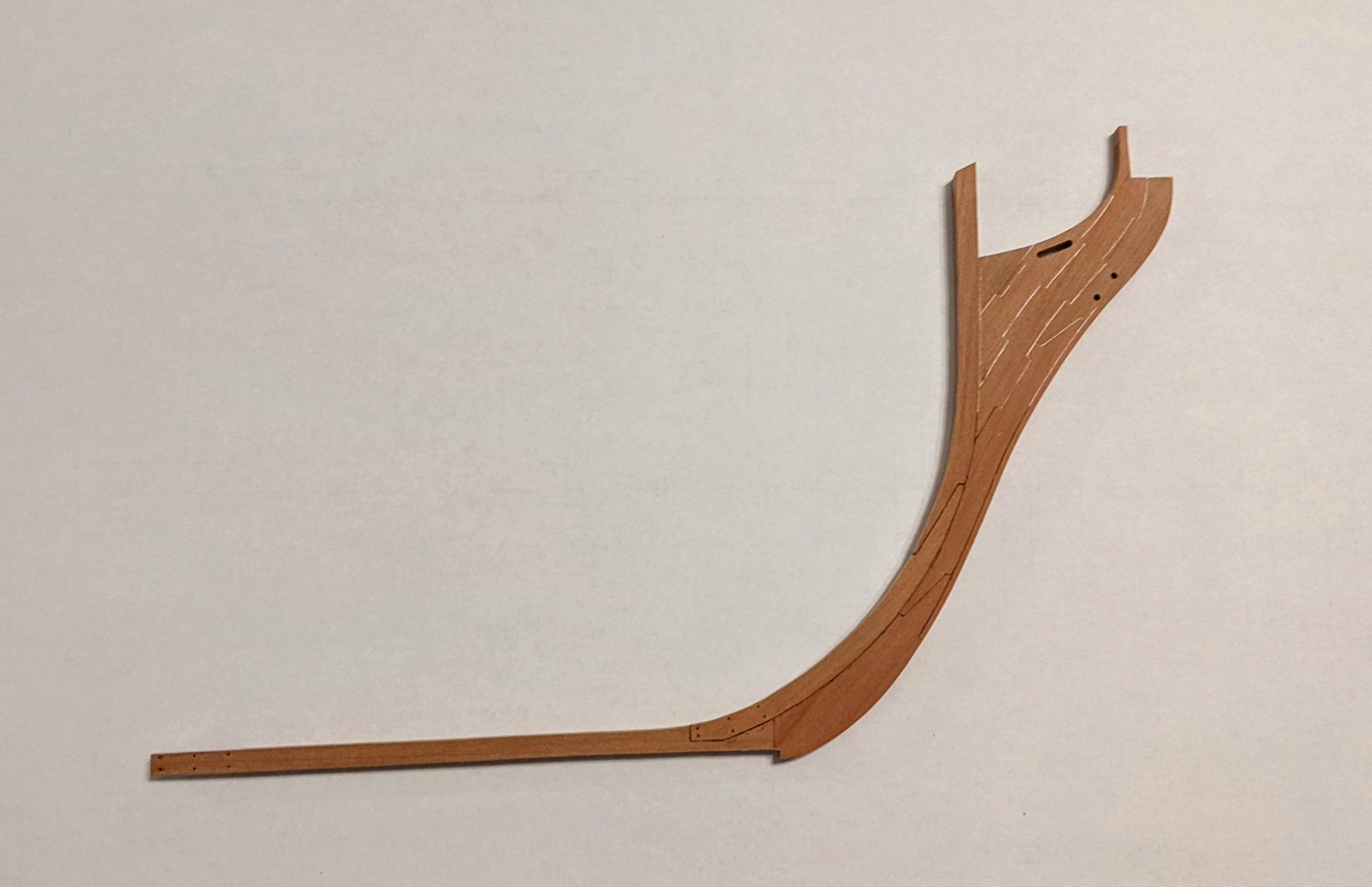
Log #22: Shaping the Head
Thanks for all your encouragement. I am much more motivated to get stuff done at the moment as progress is now starting to be visible on the model.
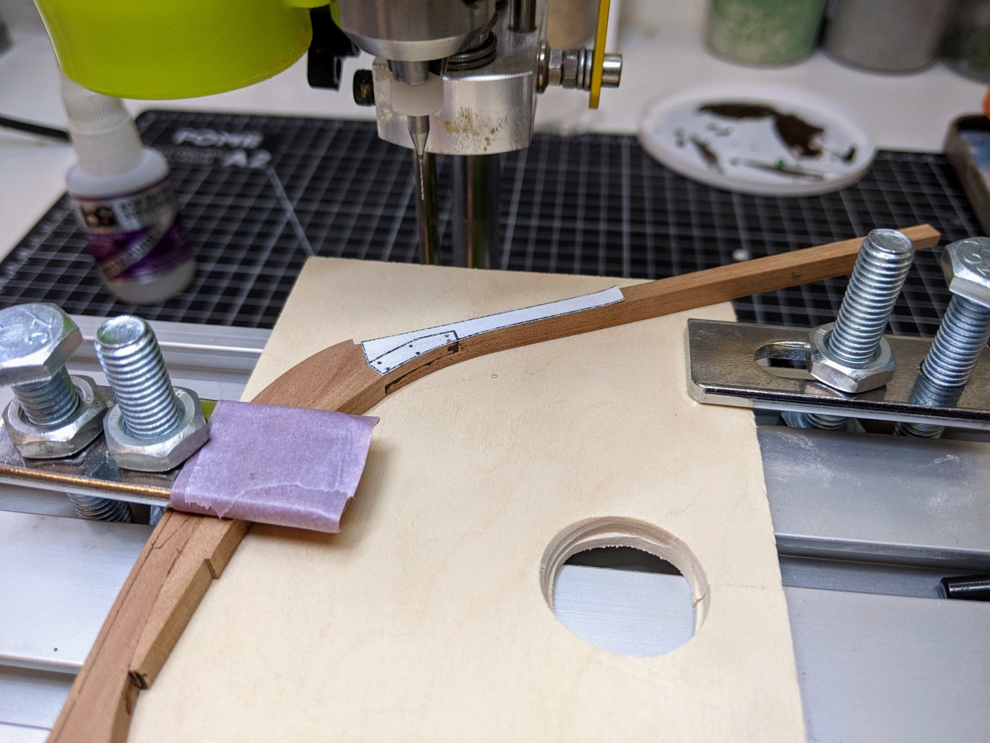
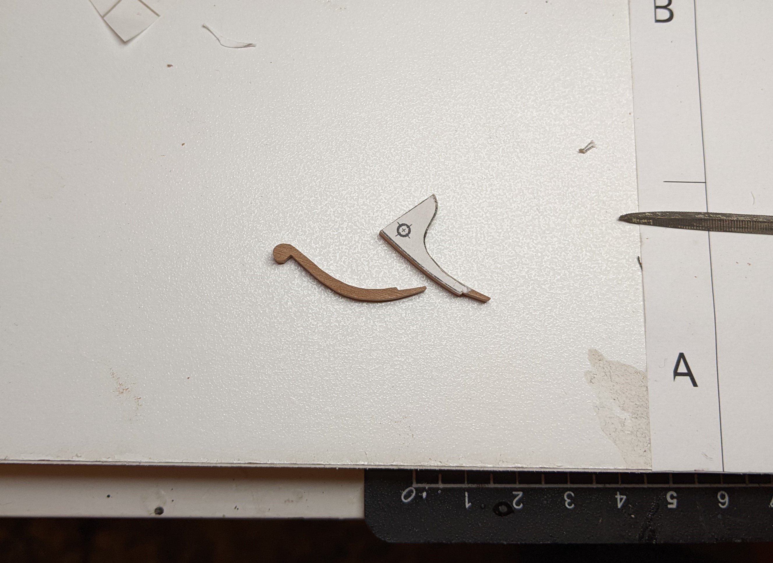
As alluded to in the previous post the next step was to get the standard in place. According to the contract this should be 7.5 inches wide and so I cut the tow pieces out using my scroll saw and used the disk sander for the outside curves as I was worried that the saw might break them (even so I had to remake one piece due to the saw tearing the end off of it).

Then it was time for small adjustments with files and chisels to get them to fit against each other and on the knee perfectly. Once happy with the dry fit, I glued the two pieces together. I used the white paint/glue mix for this joint as it will be painted black.
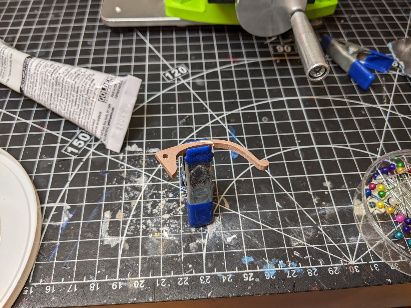
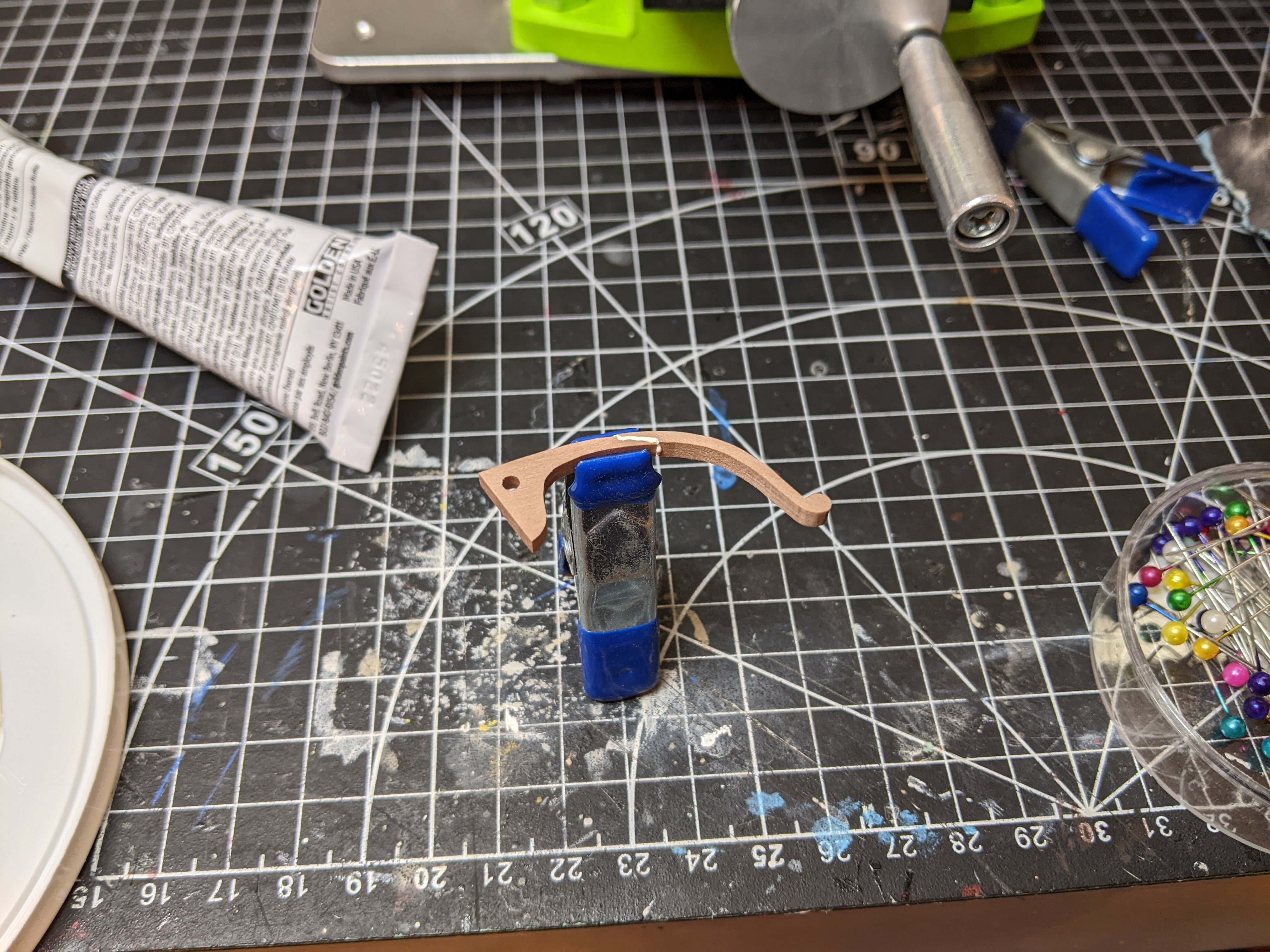
Then I clamped and glued the standard in place. I didn't use paint in my glue for this as these joints will be clear from the thickness differential between the standard and the knee.
Next came the process of deciding how to proceed with the thinning of the knee. As I discussed in a previous post, the main question in my mind was how thin to make the leading edge. My starting point for this was the Winchelsea instruction in which the knee of the head is 1/4 in thick and you are directed to thin the leading edge to 1/8 in (half the thickness). I then started to look at a number of contemporary models trying to see if I could see how much they were thinned.
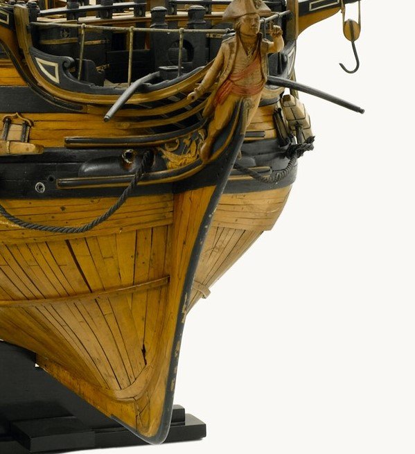
Most of what I found was very much in the ballpark of thinning to about half the width, though it is hard to be sure given the pictures are not taken head on. I won't bore you with every example I found (there were many), but I did find a very interesting model which supports my decision to use the scarfs. The model in question is 74 gun third rate made around 1790, but it is notable in that it appears to have been used as a demonstration model and all the joints are done accurately (as opposed to the simplified versions on many model).
The model does show thinning to about half the width of the knee (though not as much as is visible on other models), but you can also see scarfed joints for the various pieces of the head. Interestingly they have also depicted the lead sheathing on the leading edge of the bow.
https://www.rmg.co.uk/collections/objects/rmgc-object-66519
So with those examples in hand I started working on thinning things. I still need to make some adjustments as I have decided to thin the stem down to the width of the knee of the head below the cheeks, but here is the current state of affairs. I am thinking I may round the upper part a little more and there is still some adjustments that need to be made to the upper stem, but overall I am pretty pleased with how it is turning out.
There is still time to make adjustments so if it looks off to you please let me know.
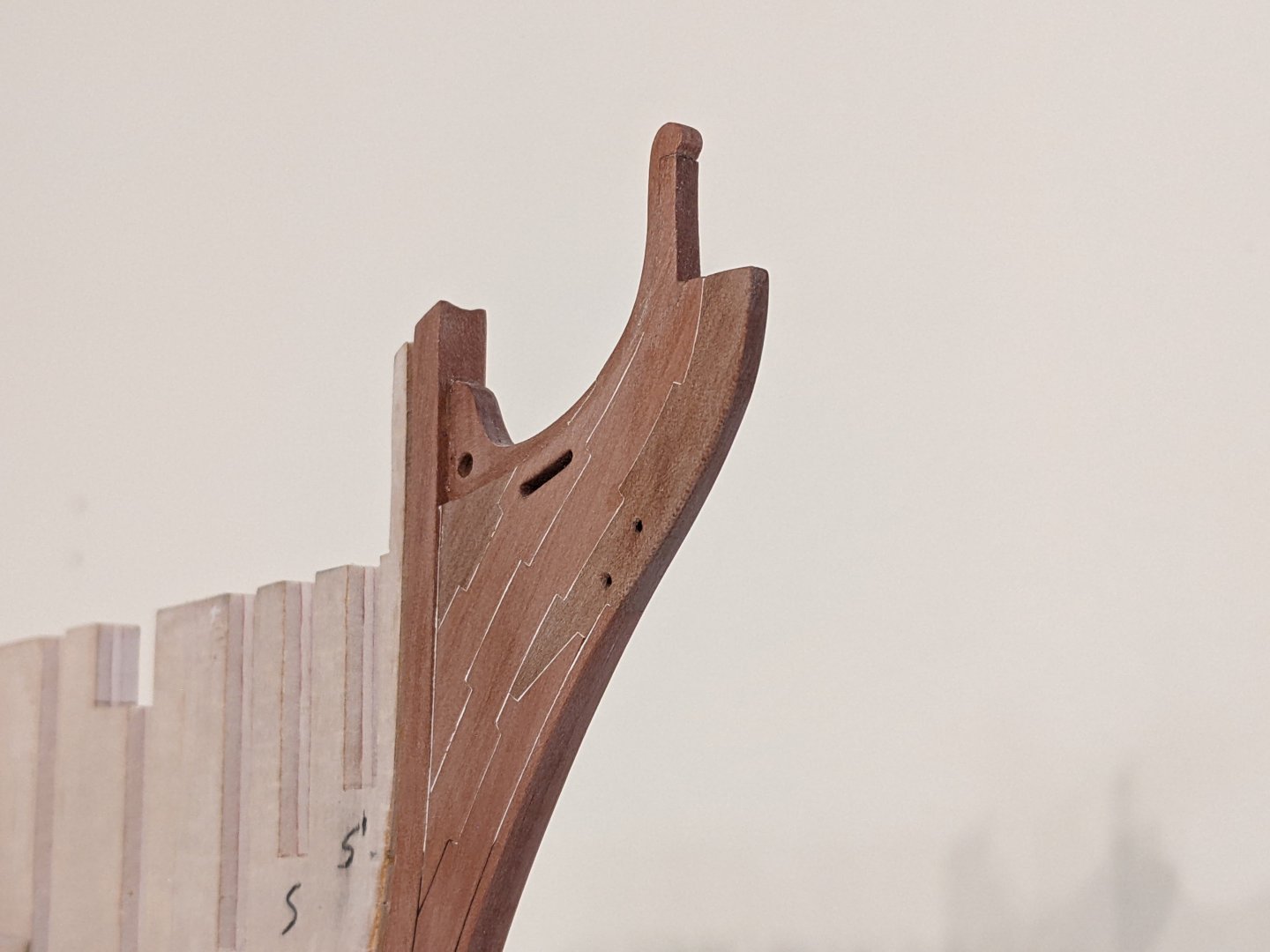
I also added the first coat of WOP which has really brough the joints on the keel to life.
- KARAVOKIRIS, Gregory, AON and 12 others
-
15
-
7 hours ago, Lieste said:
Armstrong Frederick Pattern natures, which had a simple cascable and button requiring a C*** splice on the breeching.
There are also many references to a “double thimble” used instead of a C**** splice to secure the breeching to the gun, but I have not been able to find any pictures or descriptions of how exactly it was used. These double thimbles seemed to have been often used and were part of the standard allocation of supplies as early as 1765, but were still in use as late as 1794 as they show up in another list of standard proportions of ordnance then.
- thibaultron and cotrecerf
-
2
-
Log #21: Attaching the Keel
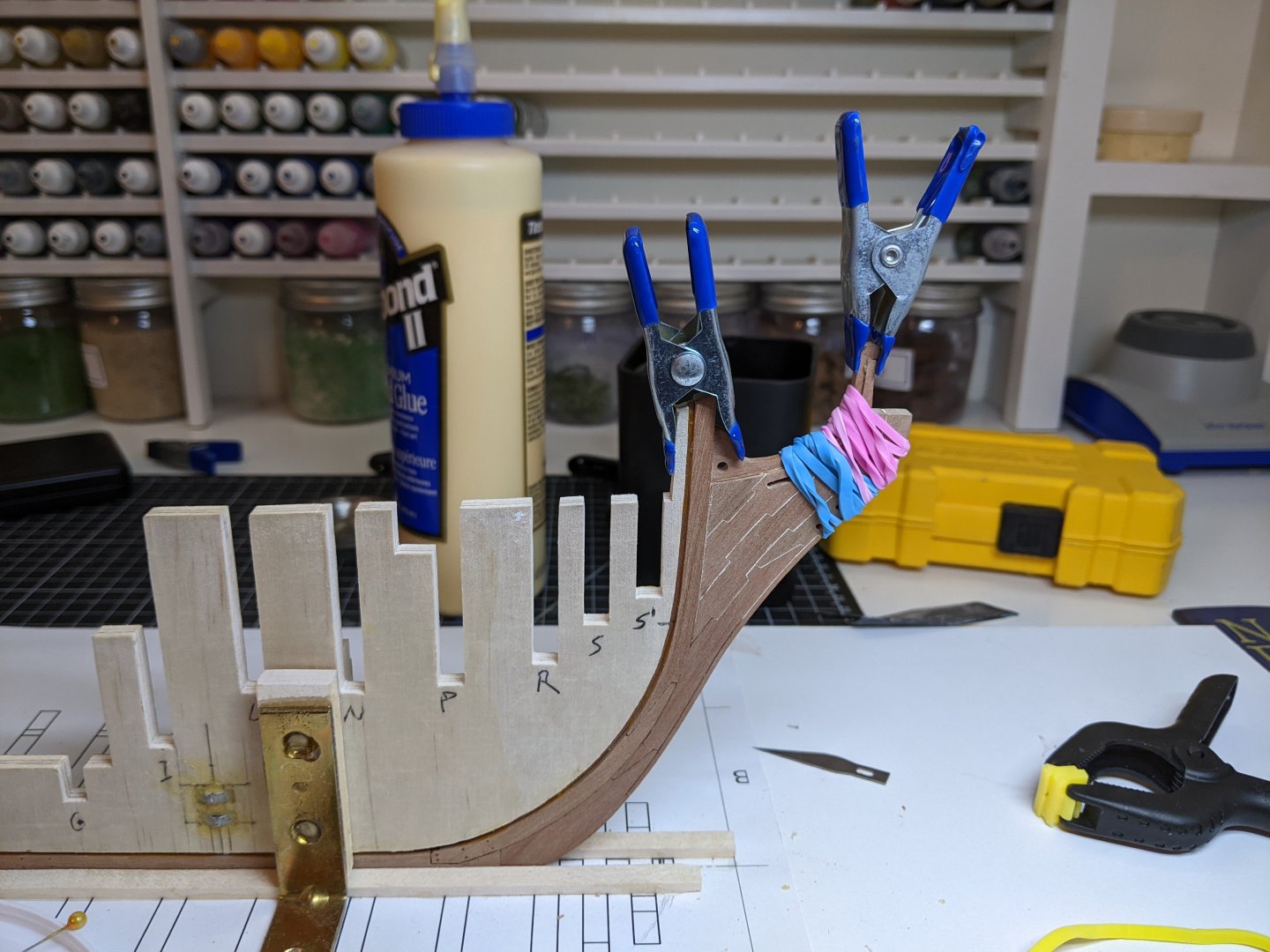
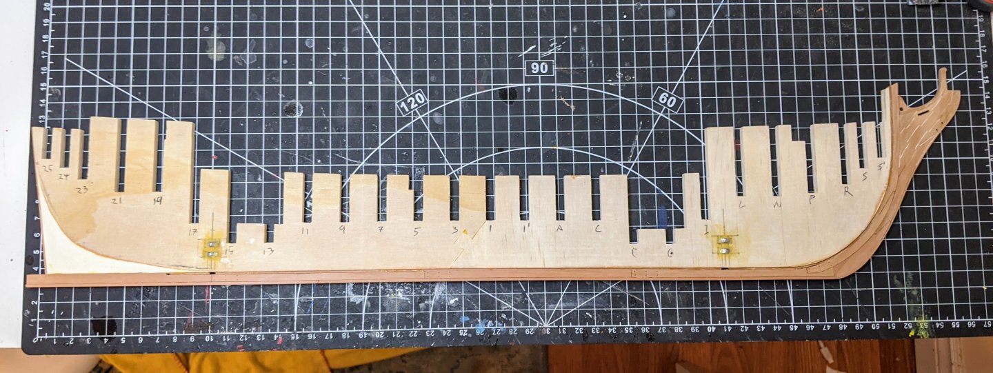
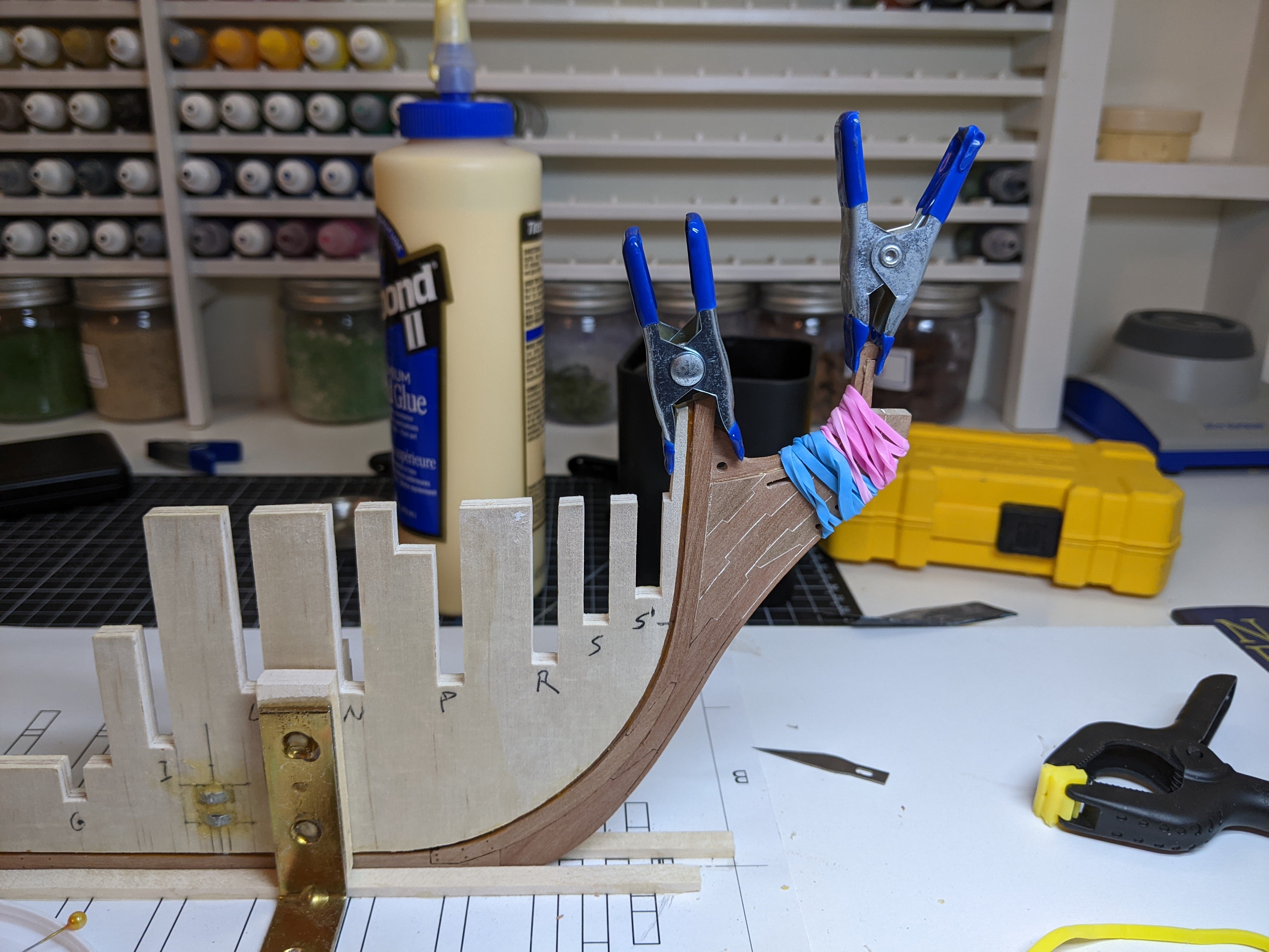
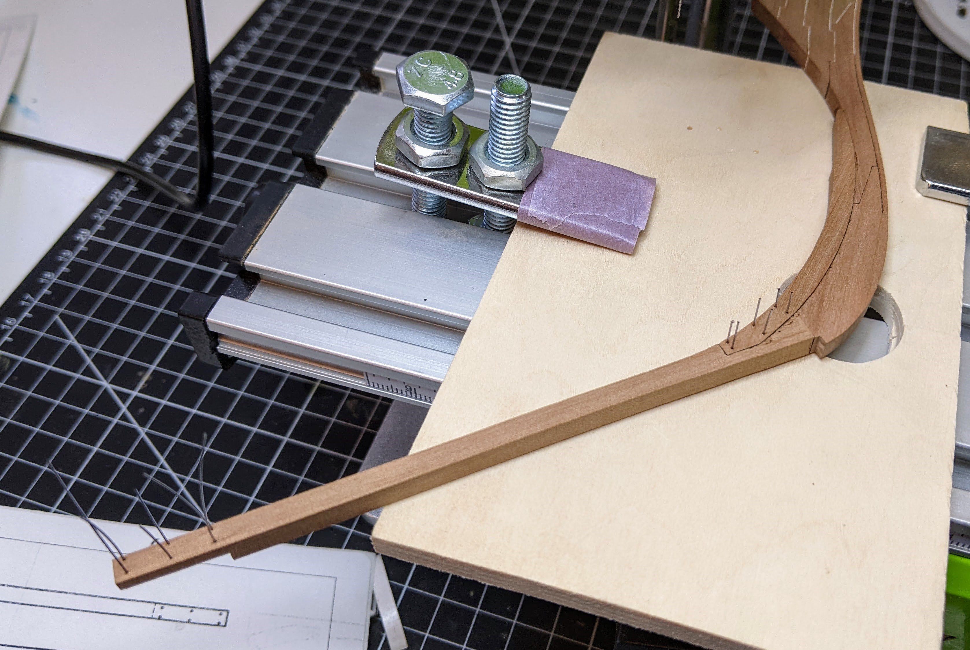
I find there are often points in a build where you face big decisions around what order to do things and in todays post we come to one of those. As you can see below, I completed the knee of the head, but it is missing the standard and not yet thinned or sanded smooth.

There is however a slight problem. Somehow there was some inaccuracy introduced into the joint between the stem and the keel and consequently the curve of the stem is a little too tight. This means that it doesn’t sit tight against the center bulkhead. There was still some flex in the assembly so with a bit of pressure I could get it to sit right, but this would be harder if I had the entire keel assembly in place and sanding couldn’t happen until I had the false keel and standard on.
So I decided that I would wait on the sanding till it was on the model. You can see below how I used a dowel and rubber bands to apply the pressure while also using clamps to hold it straight on the bulkhead.
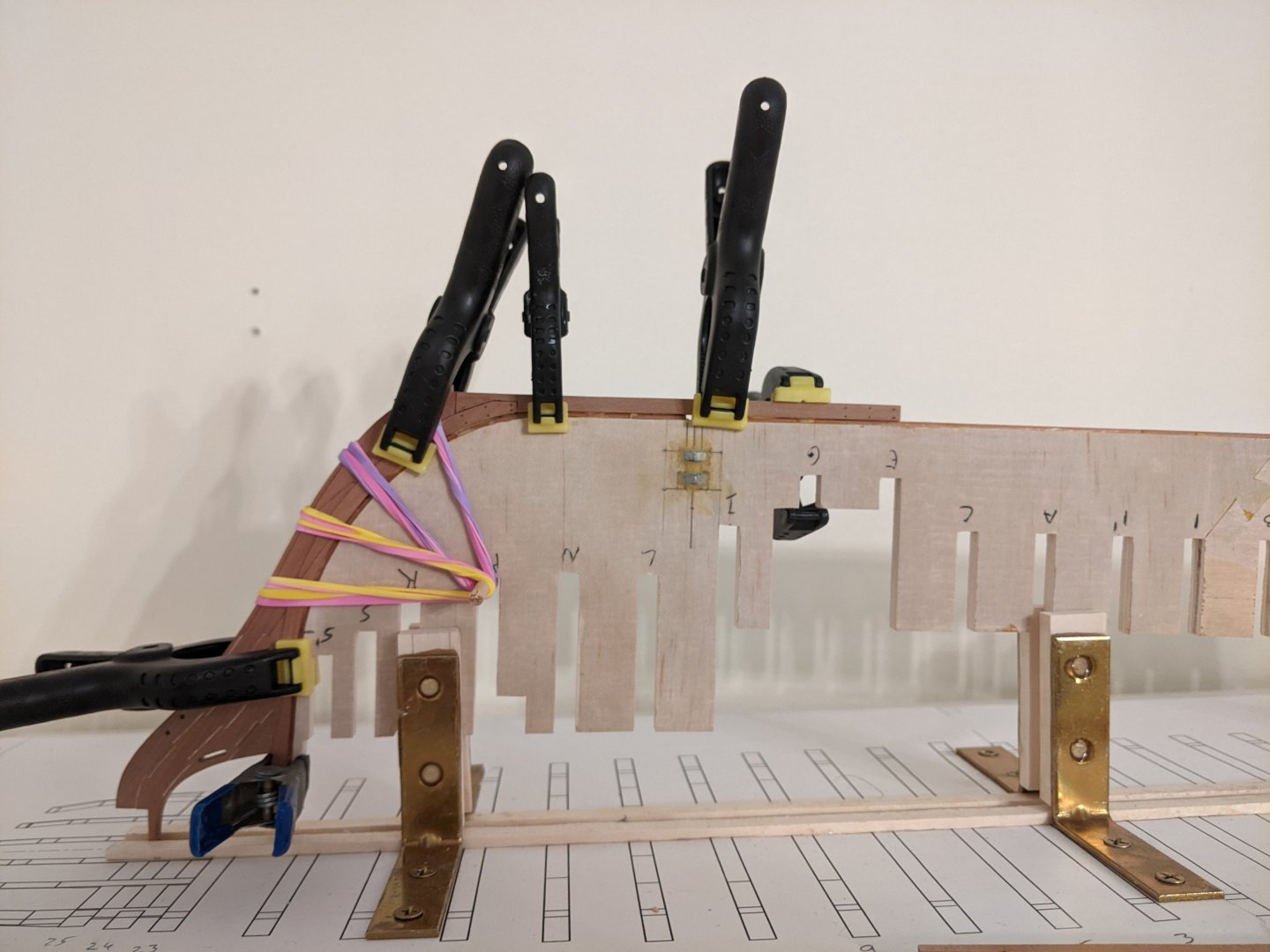
This process was then repeated for the remaining sections of the keel.
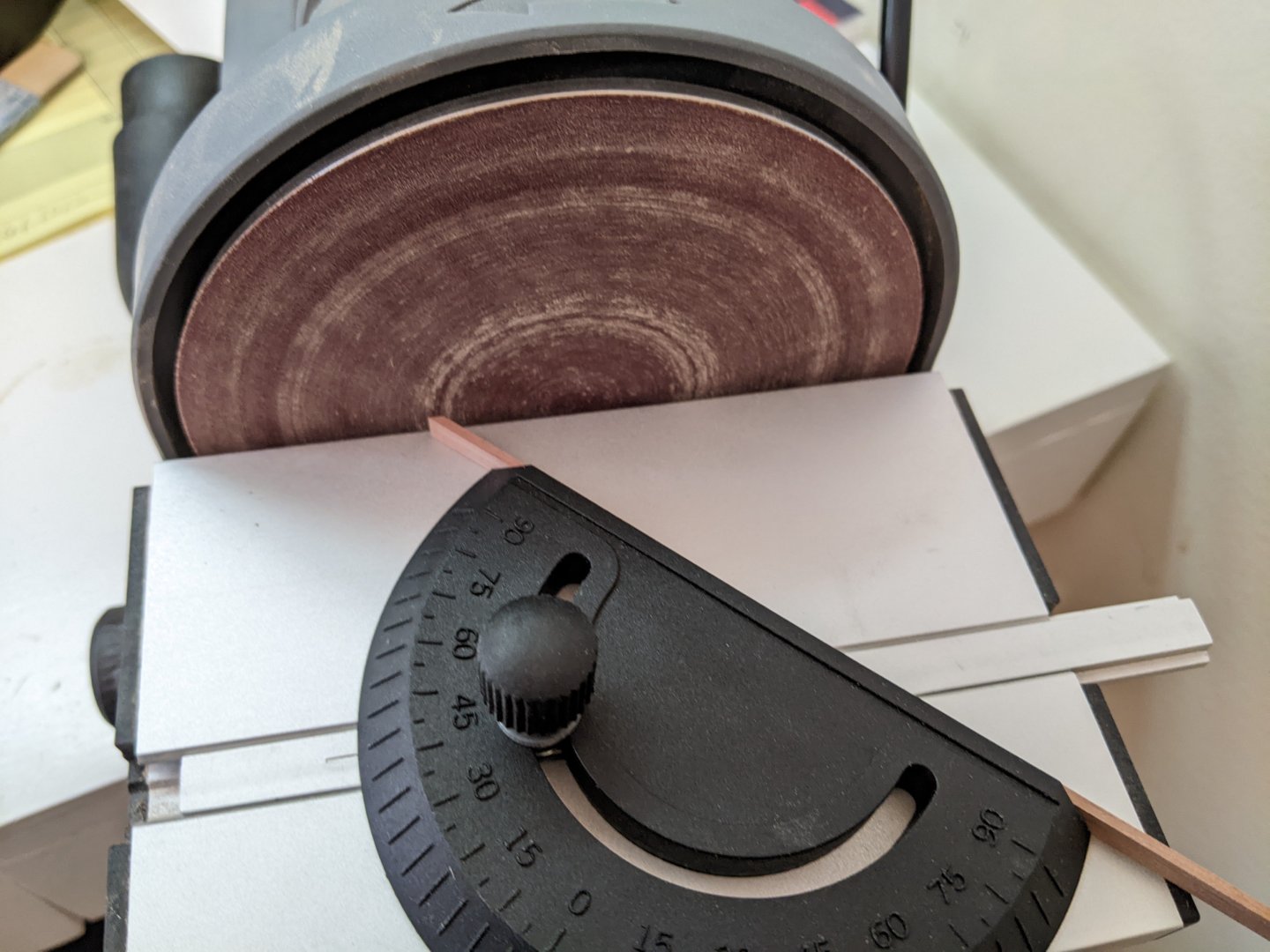
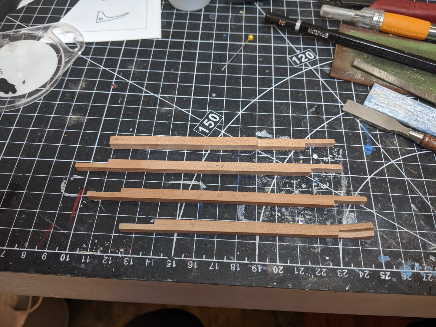
For the false keel I used 1/16 x 13/64 strips which I cut into roughly 3 equally sized pieces. I have received a disc sander recently for my birthday and I have found what it is particularly useful for is getting angles right on joints. Using it I sanded the ends of the false keel pieces at a 45 degree angle to allow them to slide over each other if the ship were to hit the ground.
I am still undecided if I will show the staples that were traditionally used to fasten the false keel to the keel. I am mostly worried things will look a bit busy and also getting them to look right at scale and at consistent intervals may be a challenge. We are also to the point where I am very cautious about doing things as corrections at this point would essentially require me to start over.
I have essentially been following chuck’s winchelsea instructions with minor adjustments up to this point and so in line with that I left the stern end of the keel a bit long and have held off on attaching the stern post until the planking is complete.
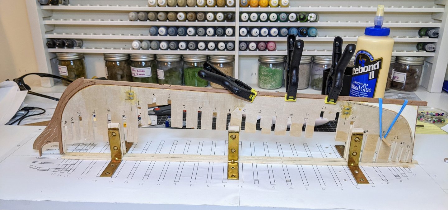
The final thing I did was carefully drill holes through the keel in line with the holes in the center bulkhead. I started very small, slowing increasing the drill bit size and then used a round file to get the final bit of the way. this was important as the screws are only slightly smaller than the width of the keel and there were risks that I would damage it.
You can see in the below picture I have the model temporarily secured to the build board with the screws. Next step is to attach the standard and make some final decisions regarding shaping of the knee of the head. She is finally starting to take shape.

- Glen McGuire, brunnels, GioMun and 13 others
-
16
-
-
It looks like a fun little kit.
- Jack12477, CiscoH and Ryland Craze
-
3
-
-
-
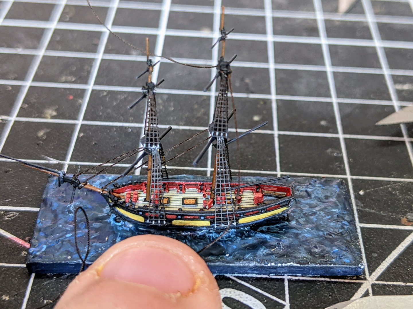
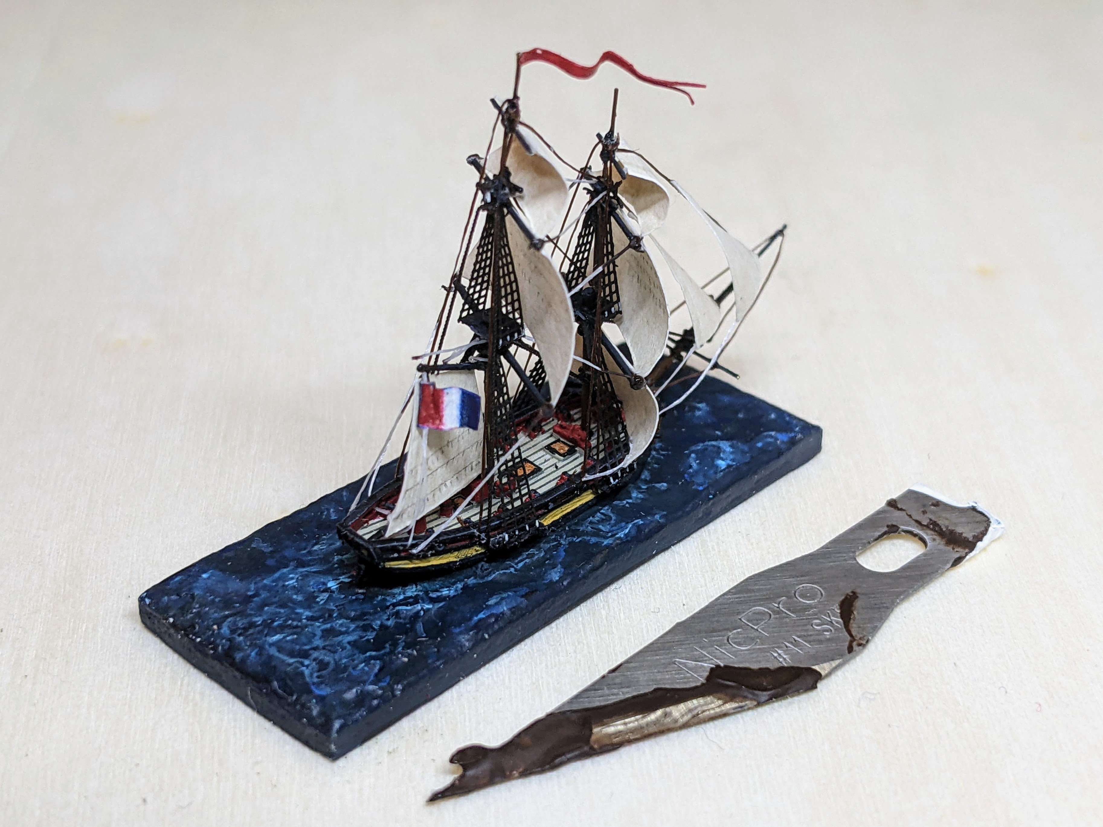
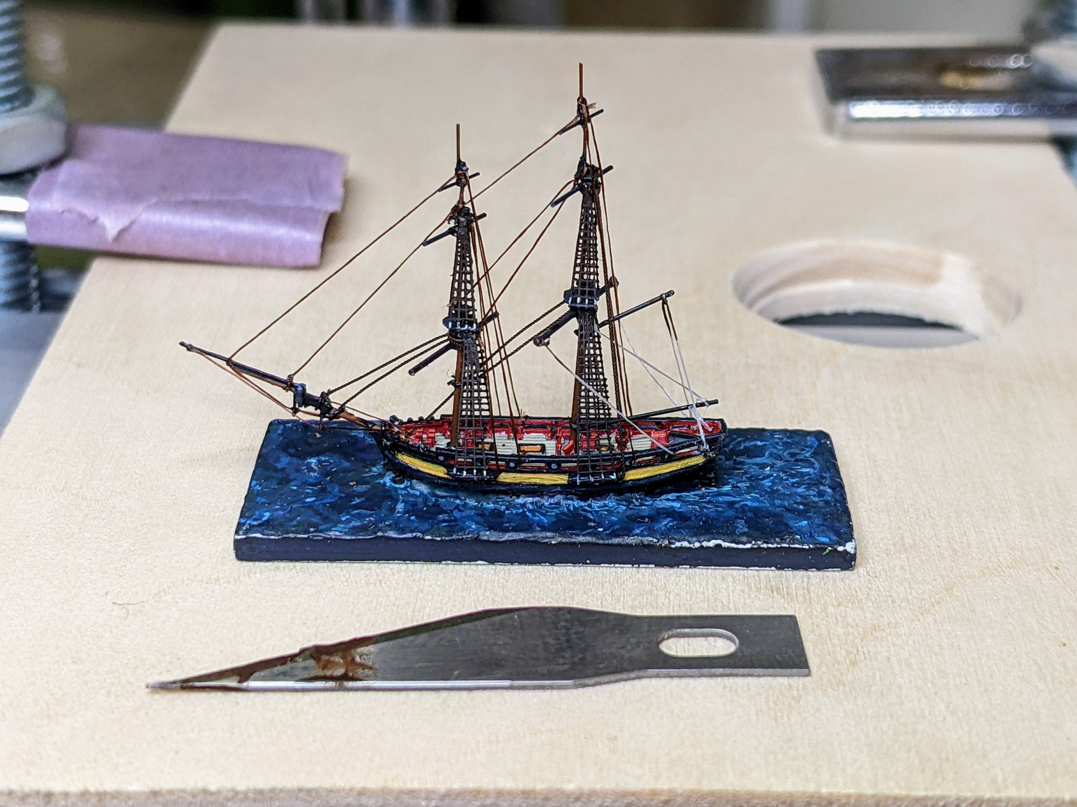
1/1200 Vigilant Class Brig - Sails & Anchors
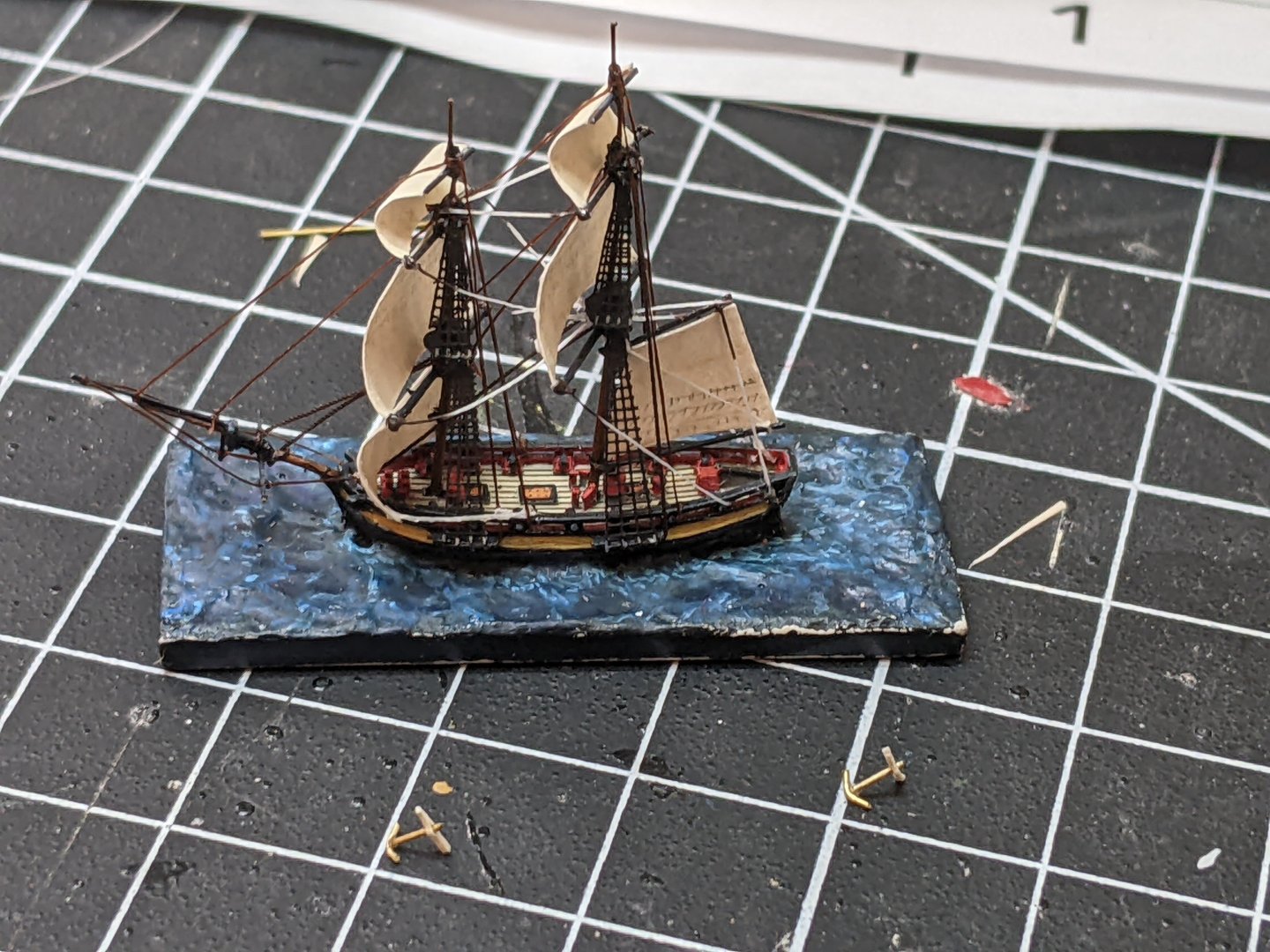
With the rigging done it was time to move on to the sails. For them I used the same paper I used for the cutters. I drew the reinforcements with a 6h pencil to keep the markings light and also used the pencil to mark the reef lines. At this point I also decided that I would go ahead and do anchors. This was the same method as I detailed for the cutters, but much smaller. Steel calls for 3 anchors for a brig, but I dropped one on the floor and couldn’t find it. I decided to just say that one was lost in a storm rather than make it over.
You can see the anchors before they were painted and glued onto the model just below the ship. Unfortunately you can also see where I used too much super glue on the sheet for the foresail. At normal viewing distances it is fine, but up close it looks a little rough. Unfortunately not much I can do about it. I tried to remove it, but couldn’t without risking damage to the rest of the model.
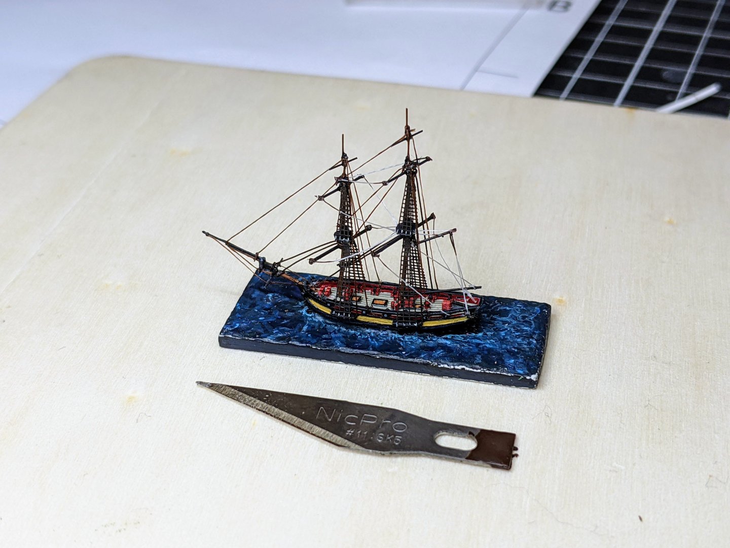
Once the sails were on I also added an ensign and a penant. The pennant was simply off cut from the sail material painted red. The ensign I printed out and then carefully with a sharp blade sliced the paper in half to make it half as thick. This I then folded over and used paint to reinforce the colours.
The model is essentially done at this point. I just need to spray it all with multiple coats of varnish to help make it more durable and then I can turn my attention to finishing the water.

-
Great job, the serving is looking really good.
I feel like serving is one of those small things which can really elevate a model.
If you decide to serve some of the smaller lines, consider getting some magnification. It helps a lot in getting the serving to lie right when you use smaller lines and thinner serving thread.
- Desertanimal and shipman
-
2
-
Minor update, I have finished rigging. Unfortunately I don’t have any pictures of how I did it as every picture I take in progress just looks like a mess. The rigging I have chosen to show is meant to be more illustrative as everything is out of scale and so if I put in too much it will look crowded. I do actually wonder if I have included too much. I would be interested in your thoughts on this if any of you have an opinion.
The only lines left to do are the sheets that will be attached to some of the sails. These I will add after the sails are in place.
- vossiewulf, JacquesCousteau, cotrecerf and 3 others
-
4
-
 2
2
-
Nice trick with the ring. Also I like the curved jaws. They do make the model look more interesting.
-
36 minutes ago, oakheart said:
Thanks, I will check Bills plans to see what angle the mast should be.
Much happier with the look of the base now.
I can hopefully also adjust the pedestals to get the keel at the correct angle to show the drag.
Tim
So I took a quick look at the plans on RMG and it may be that the speedy mast was perpendicular to the keel, you can print off the plans and measure the angle. Though the waterline is at a significant angle.
-
13 minutes ago, oakheart said:
@Thukydides Thanks for the comment, I have spaced them out further and the model is then not level, is that important?
I suppose the mast needs to be vertical, but as its not yet fixed in place, difficult to tell
as you say this is all down to a personal choice
I think it looks much better.
In terms of the angle, that depends on the waterline. Cutters had a keel drag so you need to look at the plans and make sure the waterline is level with the base. It looks pretty close to my eye, but without looking at the plans you don't know exactly how much keel drag there was.
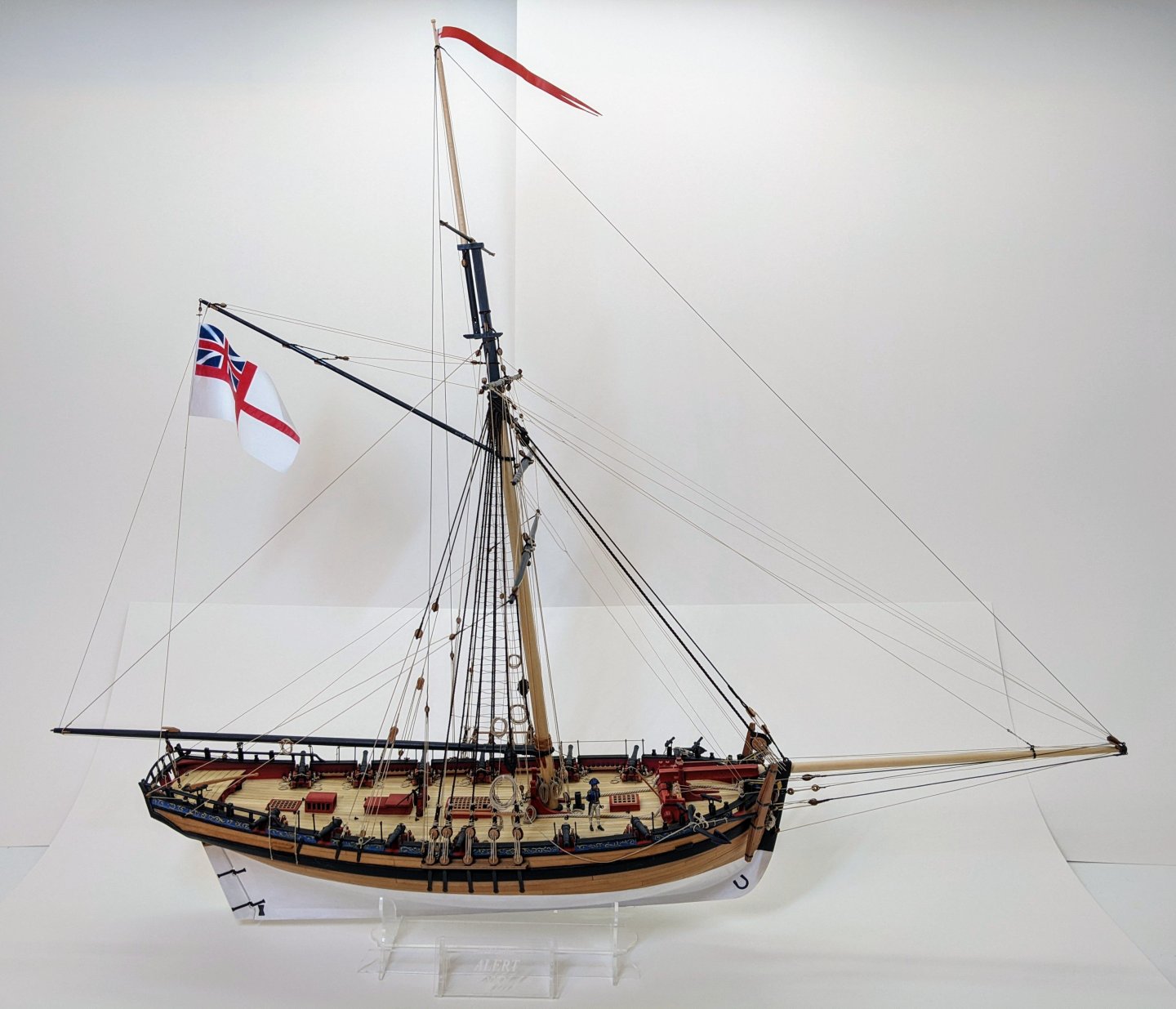
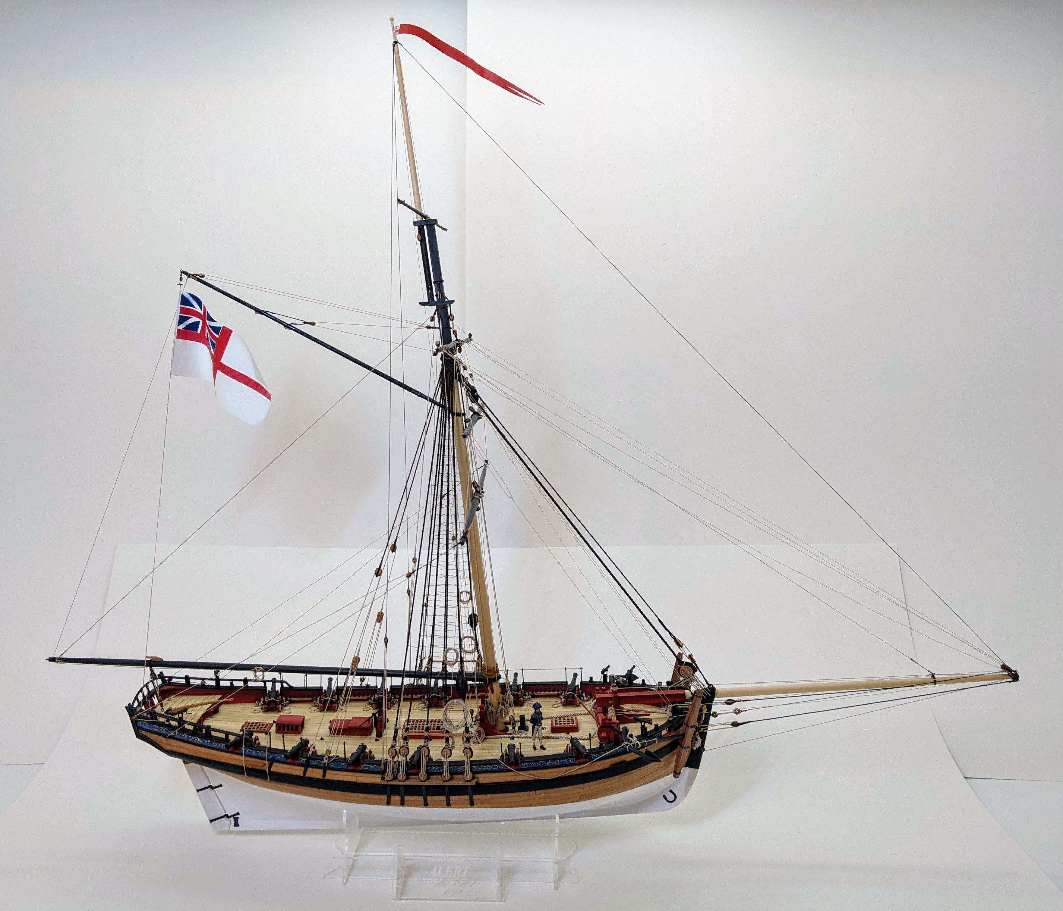
The mast on cutters is not straight, the exact angle to the keel you need to figure out from the plans. For example you can see below a picture of my alert (an earlier cutter), but you can see how far back the mast is angled.
- oakheart and Ryland Craze
-
2
-
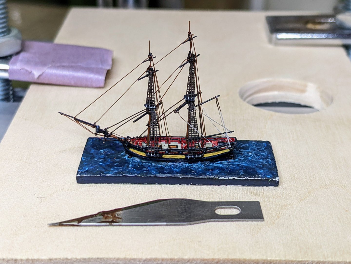
1/1200 Vigilant Class Brig - Rigging Part I
Rigging at 1/1200 scale is a bit of a challenge so I have made some decisions to both simplify and also to help differentiate the lines. Despite being out of scale, I used a larger thread for the main and fore stays as I want them to look beefier than the rest of the lines. Much of my technique is similar to the previous examples, but I have not bothered using knots to simulate blocks as they would be too big.
You can see below me tying off the backstays. I actually used the thicker line for the main topsail backstay by mistake and only noticed this as I was working on this log entry. Thankfully it is not really noticeable at normal viewing distances.
The picture below shows the current state of affairs. I have all the standing rigging done as well as the main braces and the running rigging for the boom and gaff. You may notice some damage which is inevitable when doing the rigging. Once everything is done I will go back with the paintbrush to touch up any problem areas.
I have decided that I will restrict myself to braces and sheets for the running rigging. This is enough to give a taste of things without making them too complicated. I have also been using a trick of painting parts of the white rigging brown to simulate pendants.
-
-
Log #20: Bolts, Joints & Corrections
Thanks @AON for your suggestions. I have done a bunch more research on the subject of tapering the knee of the head and found some interesting things. I will post some of my findings next time.
As research is ongoing in the background, I have continued to work on the bow and the keel. When I last updated you all, I had almost finished assembling the knee of the head. The next step was to glue the last piece in place and then make corrections to the overall shape. Overall the process has been better than anticipated in terms of wastage. I have only had to remake around half of the pieces. Most of these remakes were due to silly errors (I didn't think before cutting) as opposed to improper fits.
I had purposely left some leeway on the outer edges to allow for corrections once everything was glued together. As I am clamping at high pressure to make the joints as tight as possible, I anticipated there might be some slight bending of the pieces and so stuck a template of the overall shape in place to make adjustments with my drum sander.
Once those adjustments were done, it was time to drill the gammoning and bobstay holes. I stuck templates of the individual pieces onto the finished piece to get the positioning right. Then I drilled the holes with my drill press. For the gammoning hole I simply drilled the two ends and then used a combination of min chisels, scalpel, files and sandpaper to open of the rest of the hole.
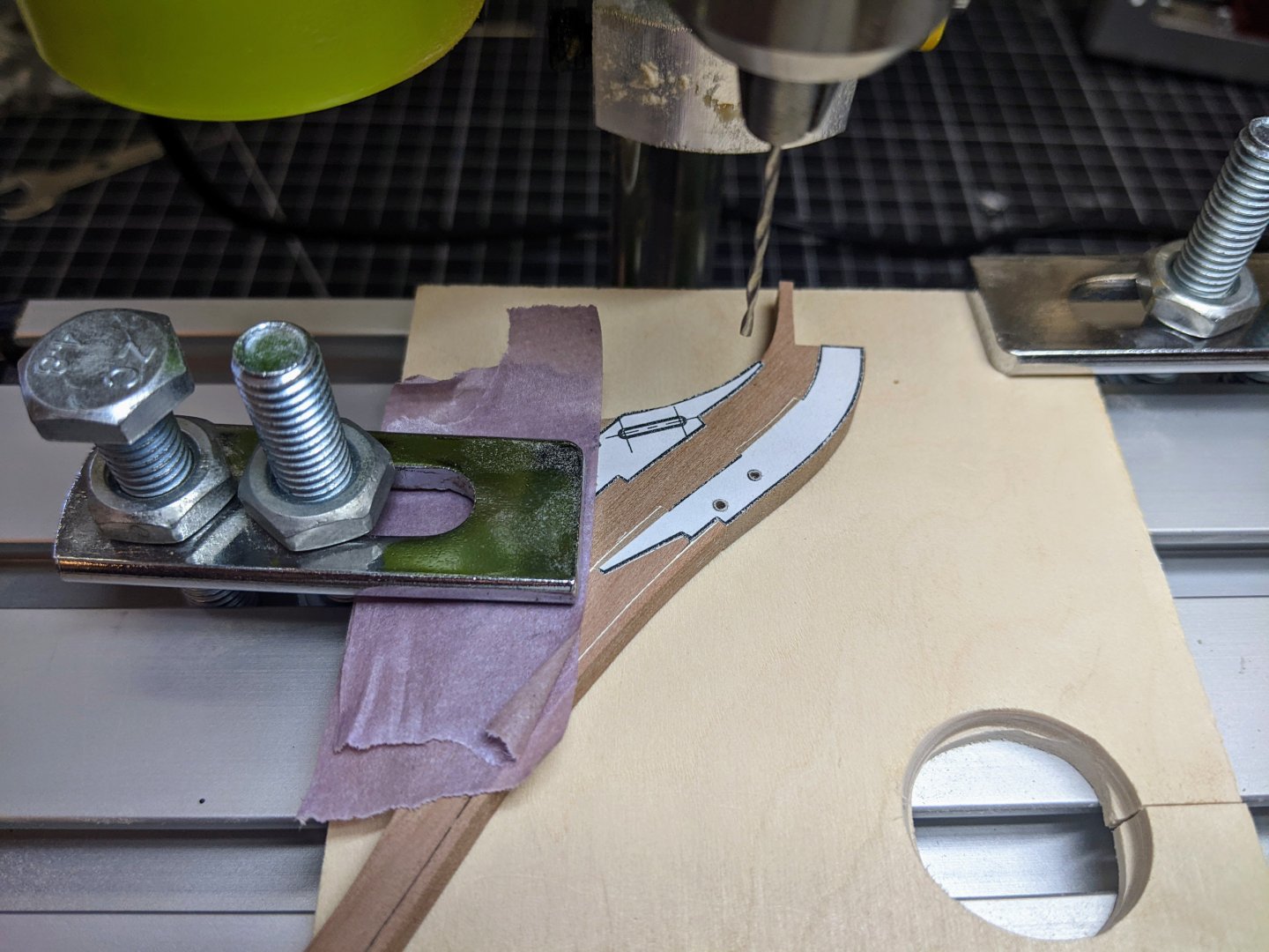
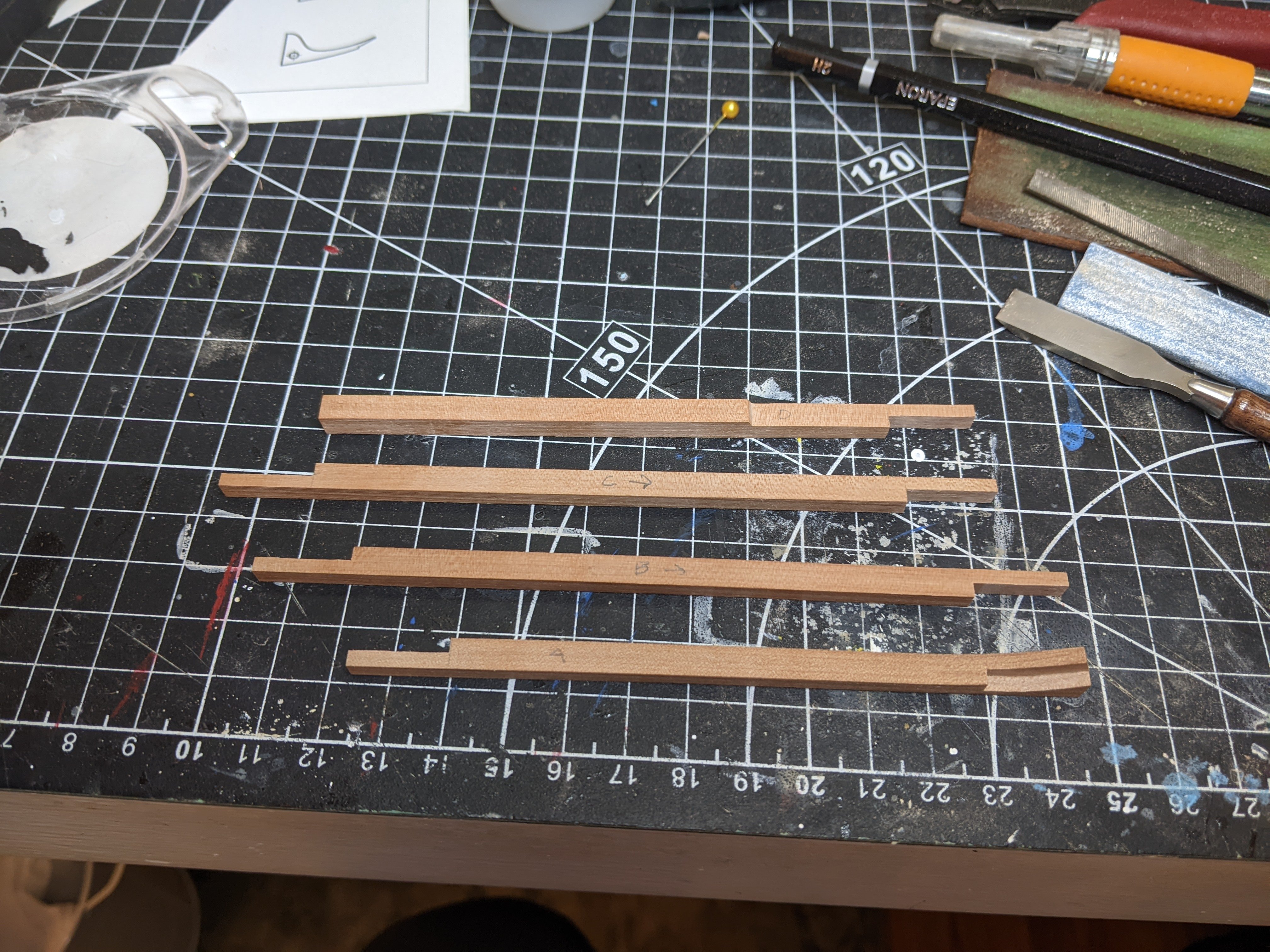
Using my mini chisels I cut out the various joints. For the keel joints I am not scarping them correctly as no-one will actually see any of those joints except the ends butting against each other. I considered simply just butting the ends together with no joints (where you can only ever see one side at once, but my OCD rejected that. You can see how I have written the part number and the direction that faces forward on the top of the pieces. Remember when I mentioned having to redo pieces because of silly mistakes?
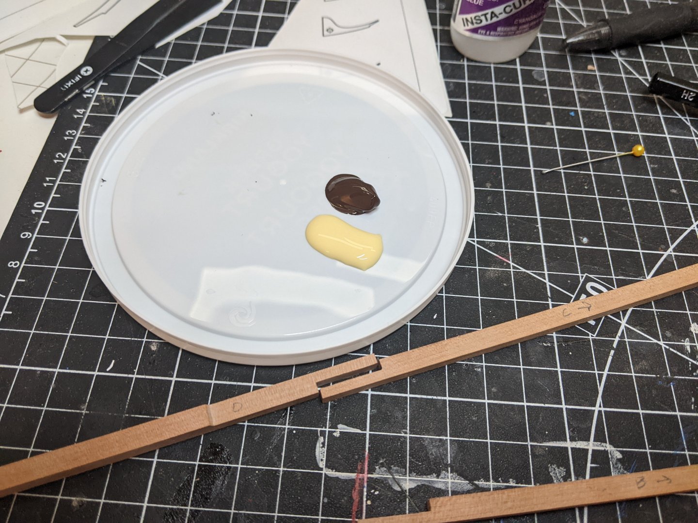
As previously noted I glued pieces together using a 50-50 mix of heavy body acrylic paint and wood glue.
Then I glued the lower stem into the fore piece of the keel and then clamped and glued that assembly to the knee of the head.
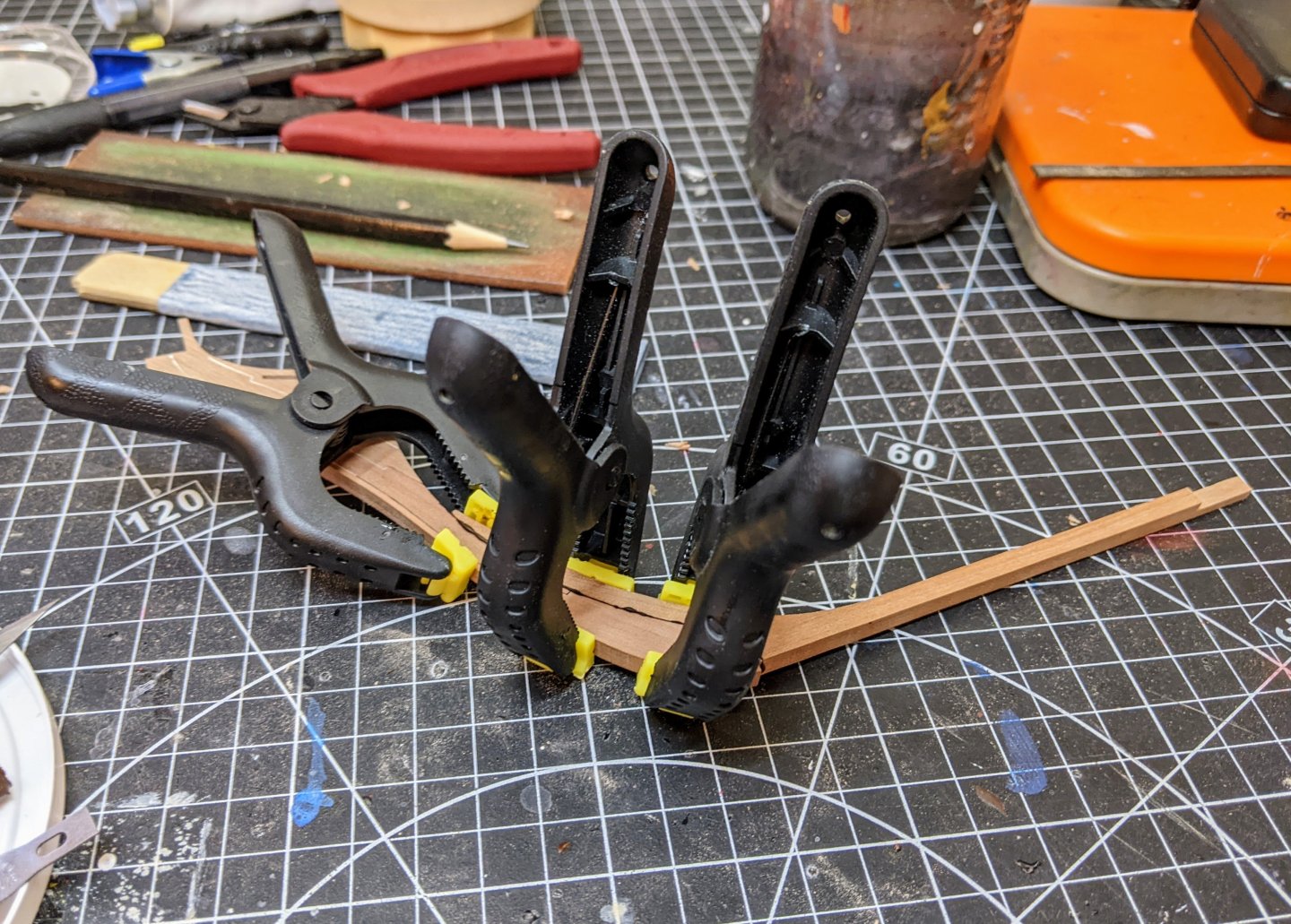
The order here is important because I need a square surface for drilling holes and so as I add thicker pieces I need to be aware of what holes need to be drilled where.
For the bolts I discovered that the black 18lb fishing line that I had left from when I used it for bolts on alert was pretty much the exact right size for the 7/8 in bolts called for by the contract. So I drilled the holes with my drill press and glued the line in place using super glue. Note that I just drilled half way and then flipped the pieces over and drilled with a new template from the other side. Any small deviations could potentially be really noticeable so I figured safer to do it this way.
You can see below the line sticking out of the holes as the glue dries. Note that I have not completely cleaned up from the gluing process as there is lots of sanding to come which will fix any glue residue still on the outside.

The final thing to note is a realized something today that I am glad I caught this early (before it became a problem). The plans I bought seemed to indicate that the waterline on the model was parallel with the keel, but when I went back and checked the various sphinx class plans, I realized that all of them show the waterline as having a small keel drag. At first I thought this might be a distortion issue, but it is remarkably consistent and pronounced across all of the sphinx plans. This does create some future problems for attaching the model to the base as I made the screws perpendicular to the keel, but the slope of the waterline is only very slight and so I figure I can probably come up with a way to adjust for it.
Thanks for stopping by and for all the encouragement.
- wvdhee, Siggi52, Ryland Craze and 20 others
-
23
-
-
As previously noted this is really a personal preference qurstion. If I was nitpicking I feel like the two keel holders are too close together.
But overall it looks good to me.
- oakheart and iMustBeCrazy
-
2


HMS Perseus by Thukydides - 1:64 - POB - Sphinx Class 6th Rate
in - Build logs for subjects built 1751 - 1800
Posted
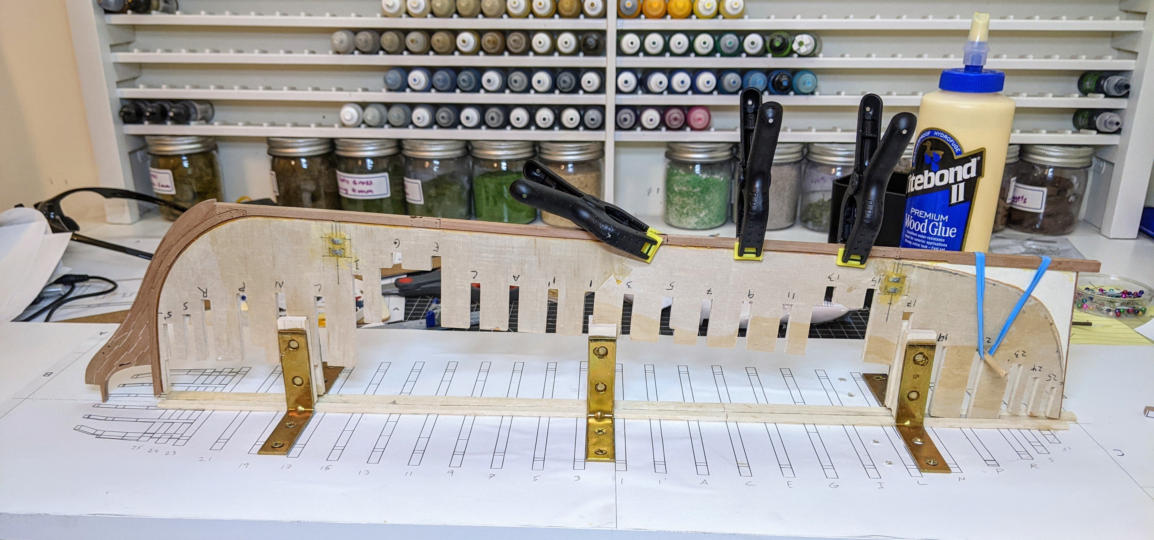
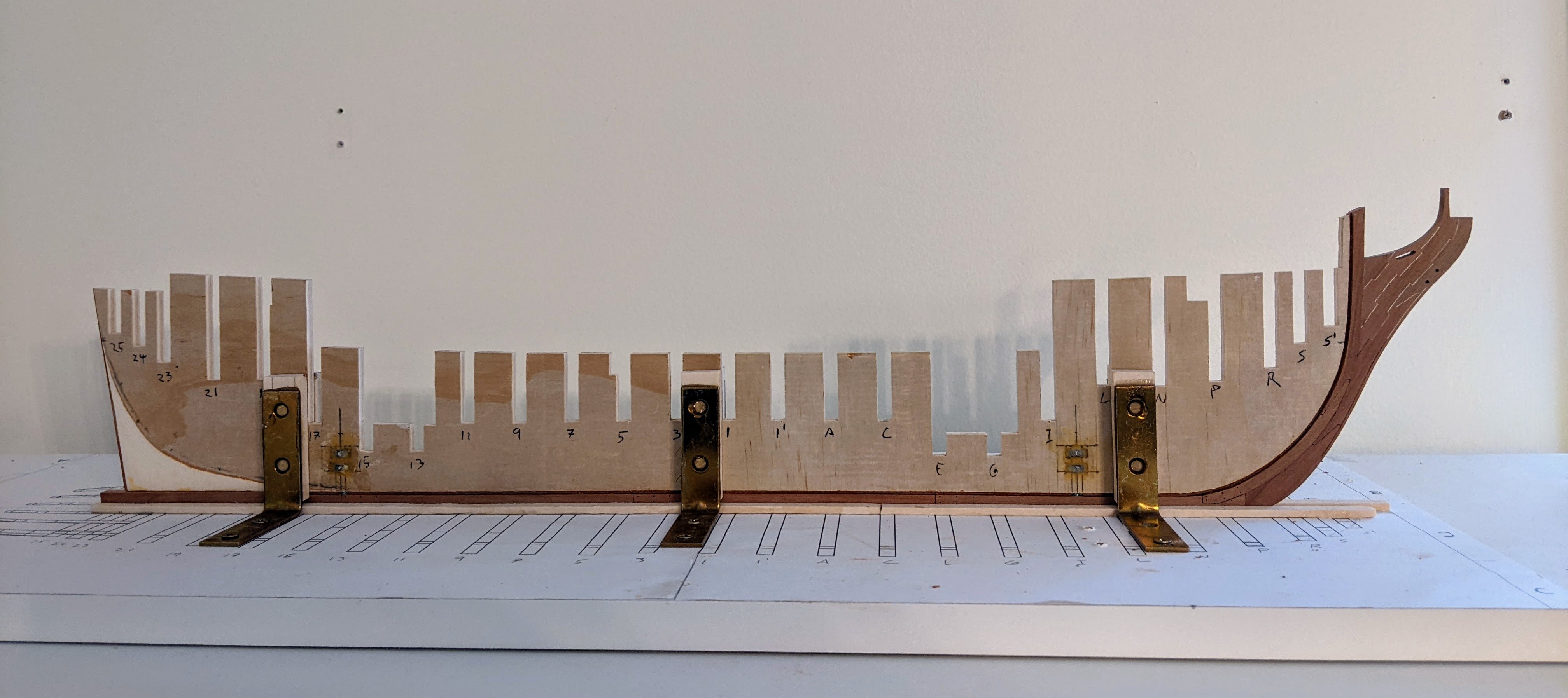
Log #23: The First Bulkheads
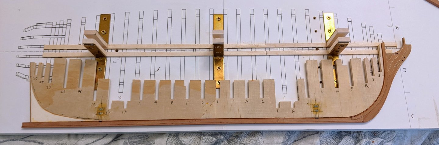
The final step before starting work on the bulkheads was I needed to mark the waterline. As previously mentioned I realized that the waterline on the Perseus is not actually parallel with the keel and so I wanted to mark the two ends of it while I could still lay the center bulkhead flat on a template.
Asthetically I am not planning on coppering Perseus, but I want to give a nod to the fact that she was coppered so I am planning on adding a batton along the waterline to mark it as if the coppering was there. This batton is prevalent on a number of coppered models, most notably the bellona model. However there is limited documentation on how big to make this so I went with a combination of what seemed reasonable, how big the batton in the bellona model looked and what looked nice on the model. In the end I used a 3/64 x 1/64 batton equating to a 1 inch by 3 inch strip at scale.
I also added a second coat of WOP below the waterline as this area won’t be painted and some extra protection couldn’t hurt.
Once the WOP was dried and sanded I covered up the keel and head with masking tape to protect it and secured the whole assembly to the build board with the brackets and screws.
Then I started adding the first of the bulkheads. I started by adding in the first two using lego to hold everything square. The lego was clamped to the center bulkhead and then the individual bulkheads clamped on both sides to the lego blocks. Lego is a convenient tool for this as it is readily available in my house and can be adjusted to a wide variety of shapes and sizes.
Then I worked backwards until I hit the last of the shorter bulkhead pieces. From this point on I worked forwards as I want to add the taller more fragile bulkhead pieces last to minimize the risk of.me accidentally breaking them.
As I approach the cut outs for the ladders from the lower deck down to the hold I needed to modify the lego shapes to make sure there was enough surface contact with the center bulkhead, but also to leave gaps to go around the nuts that screws securing the model to the base go into.
The process is not quick as I need to glue and clamp the bulkhead in place and then shape the spacer pieces such that they can slide into the gap smoothly. I then need to leave the whole thing clamped until it is dry (3-4 hours to be on the safe side). I am also being very careful as I want to make sure everything is square and good. Mistakes at this point could be a big problem later on if I don’t line everything up right.
This is a very encouraging part of the build as after a lot of prep work the shape of the ship is starting to take shape.