
Thukydides
-
Posts
1,271 -
Joined
-
Last visited
Content Type
Profiles
Forums
Gallery
Events
Posts posted by Thukydides
-
-
-
As previously noted this is really a personal preference qurstion. If I was nitpicking I feel like the two keel holders are too close together.
But overall it looks good to me.
- iMustBeCrazy and oakheart
-
 2
2
-
-
Good job on the planking.
I don't think your bulwarks look too high, they are meant to vary in height along the length of the deck. What I did is just planked starting from the bottom and then when I got to the top I let the planks go over the top. Then once everything was glued in place I sanded / filled it all down to match the height of the inner layer.
-
-
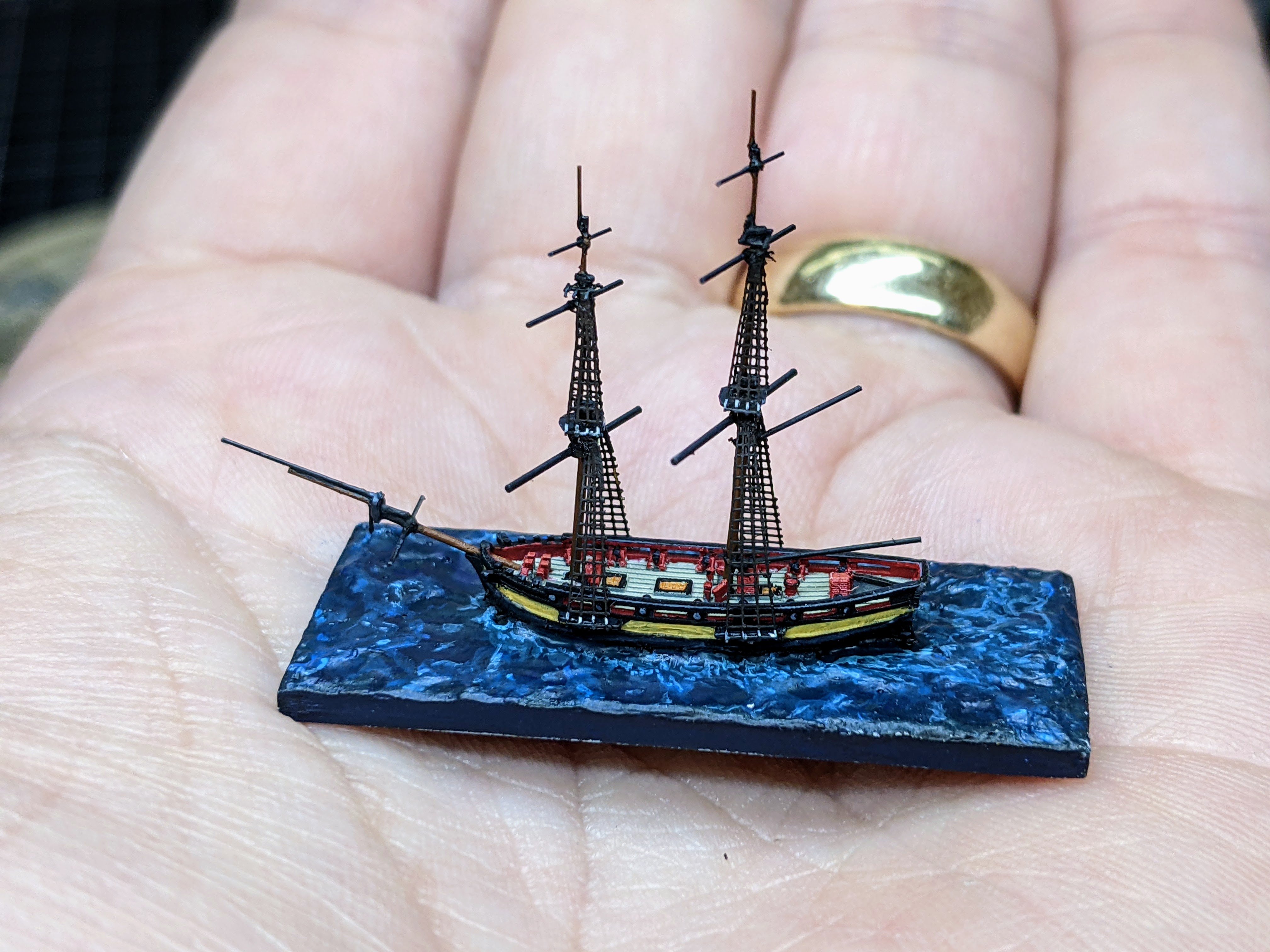
1/1200 Vigilant Class Brig - Painting Part II
After painting the hull, the next step was to paint the seascape and attach the masts. Before glueing the masts in place I painted the bottom masts as accessing this area will be hard once they are in place.
The seascape I painted in a similar manner as previously discussed. I first laid down a thick layer of may darkest colour (dark sea blue) and then started wet blending in increasingly lighter blues to create contrast and the illusion of depth. I focused the lightest colours on the tops of the swells, the area around the hull and the wake. At this point the sea is done until I varnish the miniature as I don’t want to add the final water effects until everything else is in place.
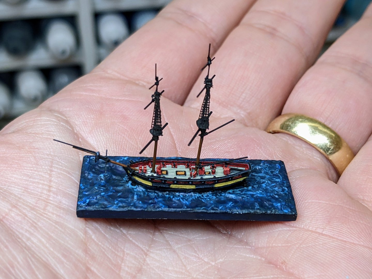
My tying of the yards to the masts has done a really good job of securing them as being clumsy I keep bumping them, but so far nothing has snapped off. You may also notice in the above picture that I added royals as I had forgotten them when I first constructed the masts.
Next up was painting the masts and yards and then finally attaching the lower shrouds. This is a very fiddly process and a lot of touching up is required due to paint rubbing off. As the shrouds I am using are oversized, I can’t use the deadeyes and lanyards that come with them (they would look really out of scale). So instead I simulated lanyards by painting the bottom vertical segments of each set of shrouds a pale cream colour to give the impression of lanyards.

Though the shrouds are not the correct scale. At this small a size, like the planking on the deck they actually do a pretty good job of selling the illusion of the model. Next up I need to start considering what rigging I am going to show.
-
6 hours ago, Rich_engr said:
Now that hull and deck are mostly finished, onto the mast and spars...
Also semi-thinking of adding sails (furled on the yards/boom, etc)... haven't decided yet... if I do go with sails, have to do them before adding the standing rigging I think...
I like to work up as I go. So have everything built but not glued together. Then I do the mainmast and all the associated rigging then the topmast etc. The main advantage of this is it lets you make the shroud eyes (and serve them if that is what you plan to do) off model and then slip them over the top of the mast instead of having to try and seize them on the model.
For the yards I rig as much as I can on them (this would include the furled sails) off model. It is much easier to do things off model. Then you attach the finished yards to the mast. If you are pinning them, make sure you drill the holes for the pins in the mast before adding it to the model (again much easier to do off model).
-
Amazing work. She is really coming together now.
- Baker, Old Collingwood and Slowhand
-
1
-
 2
2
-
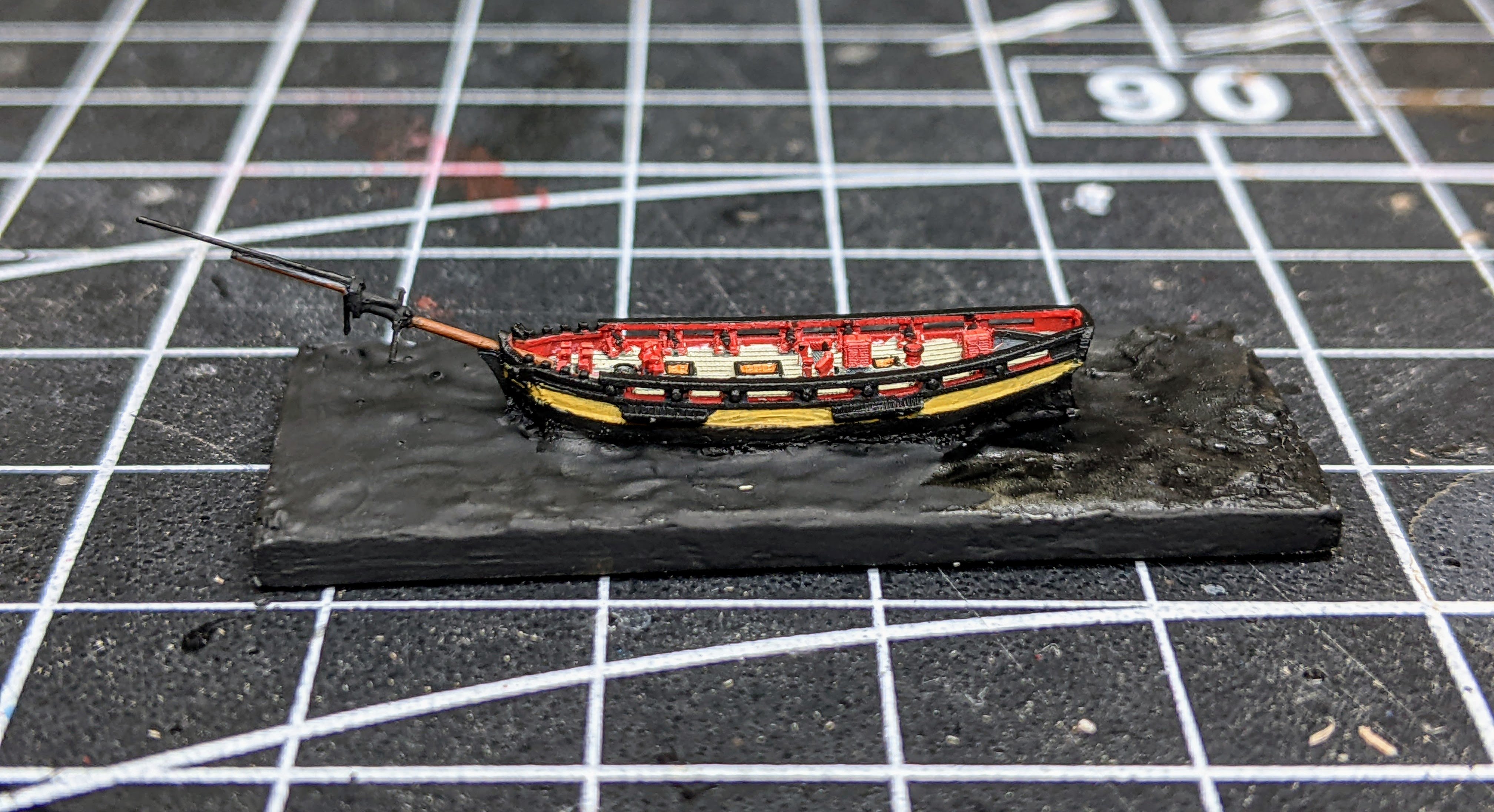
1/1200 Vigilant Class Brig - Painting Part I
To help with the problem of painting something so small I decided to use my airbrush to spray on the deck colour. I found in my 1/700 models that it was actually hard to get a smooth coat for the deck with a brush given the hard to reach areas. You can see that even though they are out of scale, the upper shrouds look fine at a distance.
One advantage of painting at this small a scale is you don’t really need to get your placement perfect as at normal viewing distances it will not really be noticeable. I have the base colours down for the hull, but given the small scale very little will be necessary in highlights. Essentially I will be just picking out the upper faces with a lighter version of the base colour.
I recently got some dentist loupes off of amazon (the cheap ones). These are a big improvement on my previous magnification glasses, but they take a bit to get used to as they are designed for proper posture (so I don’t need to bend in close), but I have to unlearn all my previous habits regarding where my hands go relative to my face.
To give a sense of scale, the squares on the matt are 1cm and the entire base is about 4cm long. Zoomed in this close you can see some of the printing layers, but they are not really visible with the naked eye.
-
23 minutes ago, AON said:
I drew an imaginary line from B to D and from A to the Gripe horizontally opposite D and tapered the stem to these points along these lines. It made sense to me.
So if I understand you correctly A would have been thinner than the leading edge of the gripe and from D horizontally to the leading edge of the gripe you did not taper? Or should the leading edge of the knee of the head be the same thickness all the way down?
-
I second @wefalck's suggestion. I find template really helpful.
I had not noticed you started another build till now. Great job so far and I look forward to seeing her progress.
-
-
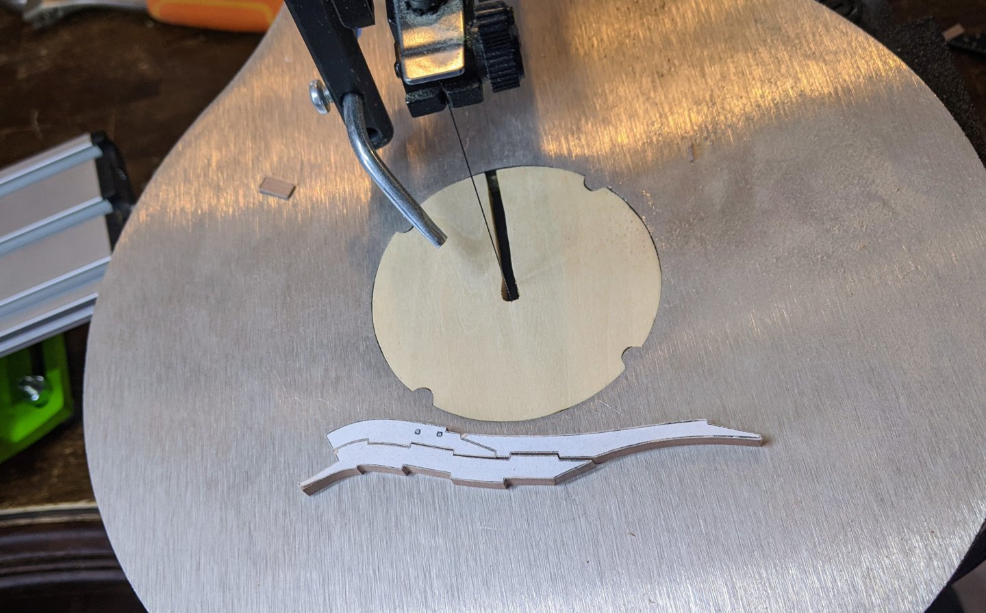
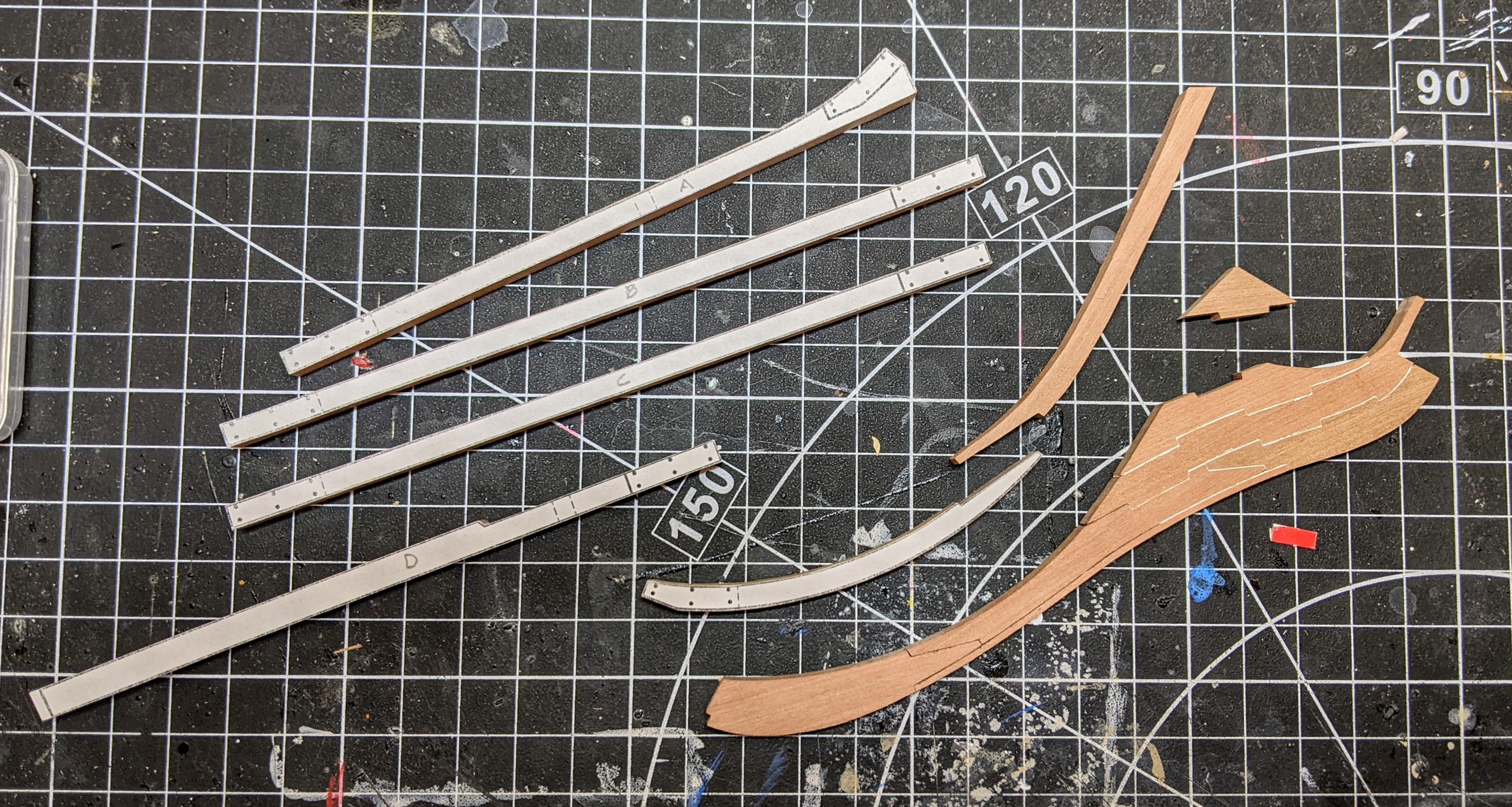
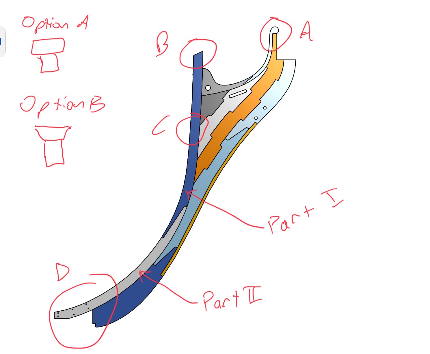
Log #19: Beginning the Knee of the Head, Stem and Keel
I have begun work on the knee of the head, stem and keel. Step one was to cut the parts out using my scroll saw which I have now found I can be pretty accurate with if I go very slow and use magnification.
I also discovered that it is best to glue the pieces as I go. This allows me to adjust the fit of every new piece to match what I had previously cut. As previously indicated, I am gluing the pieces together with a 50-50 mix of heavy body acrylic paint and glue. You can see in the below picture how the glue spills out, but due to it being so thick, it does not stain the surrounding wood. The lines still look a little rough, but that is just due to the fact that even very small discrepancies in the alignment when clamping can lead to the lines looking untidy. Once I start sanding they will look much more neat.
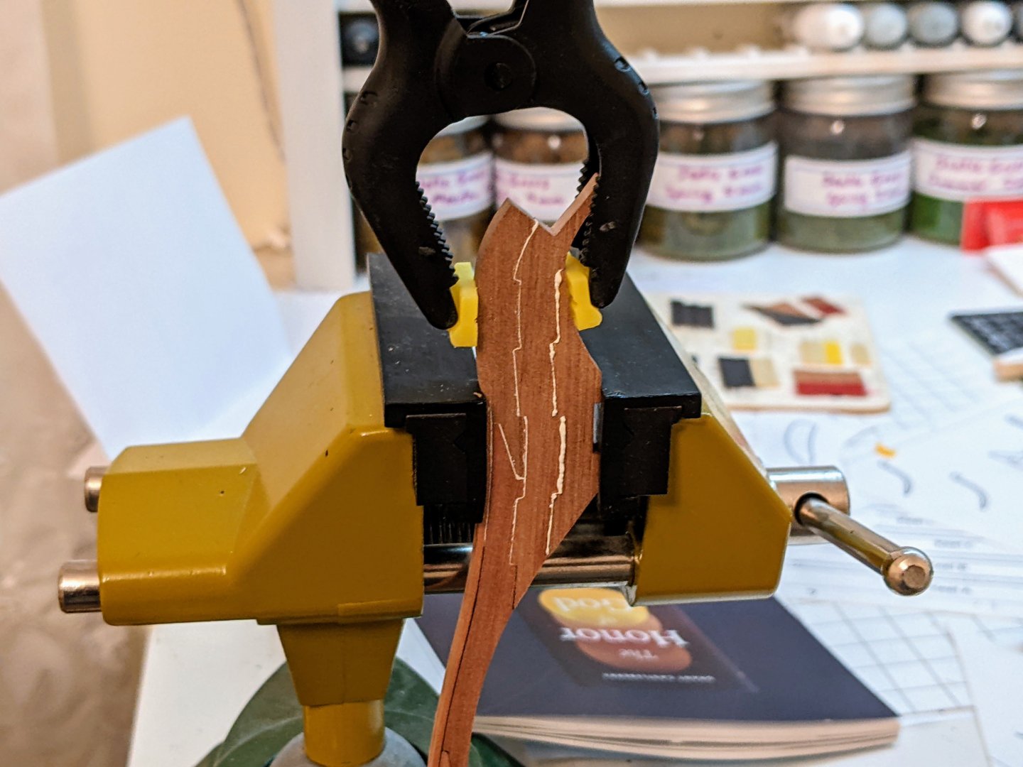
You can see how I have used darker glue up to the waterline and white above that. As it is impossible to be super precise with the glue placement, I erred on the side of having dark glue above the waterline as I can always paint in the white line if necessary.
I have also cut out most of the other pieces though many of them need final shaping. You can see the current state of affairs below:
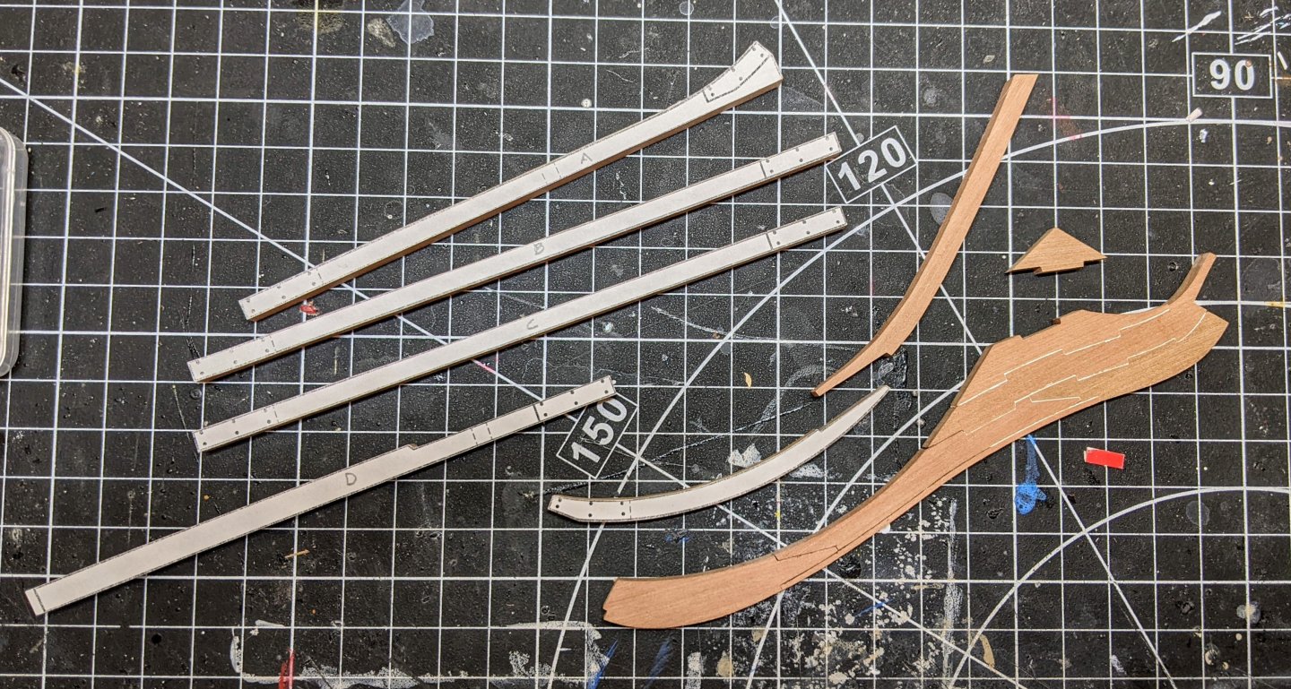
Once I am done shaping and am sure everything fits properly I will drill the necessary holes. Then I can give thought to sanding and shaping.
As I am preparing for final assembly and shaping I have been giving some thought to the thinning of the knee of the head. I have a few questions which I am wondering if anyone is able to help clarify for me.
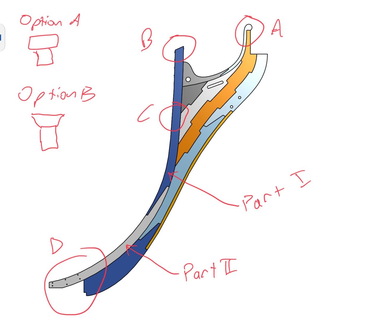
Due to measurements given in the contract I know that the thickness of the knee of the head at point A is 7.5 in (matching the width of the standard which is given in the contract), 15 in at point B (given in the contract), at some point below point C the stem thins to 13 in (the thickness given in the contract “below the hance”) and then finally thins to 11 in at point D matching the width of the keel at the fore end.
What I am struggling with is the following:
- How quickly should the upper stem (part I) thin from 15 in to 13 in below point C?
- How quickly should the lower stem (part II) thin down to the 11 in given for the keel at the fore end?
- The thickness of the knee of the head is given at 11.75 in. Where the stem meets it, does it look like option A all the way down until it matches the thickness of the knee of the head, or does it ever become like option B?
- How thin should I make the leading edge of the knee of the head? There is no indication of the relative ratios in the contract.
- The fore end of the keel is given at 11 in, does this mean that the leading edge of the gripe would be thinner still?
-
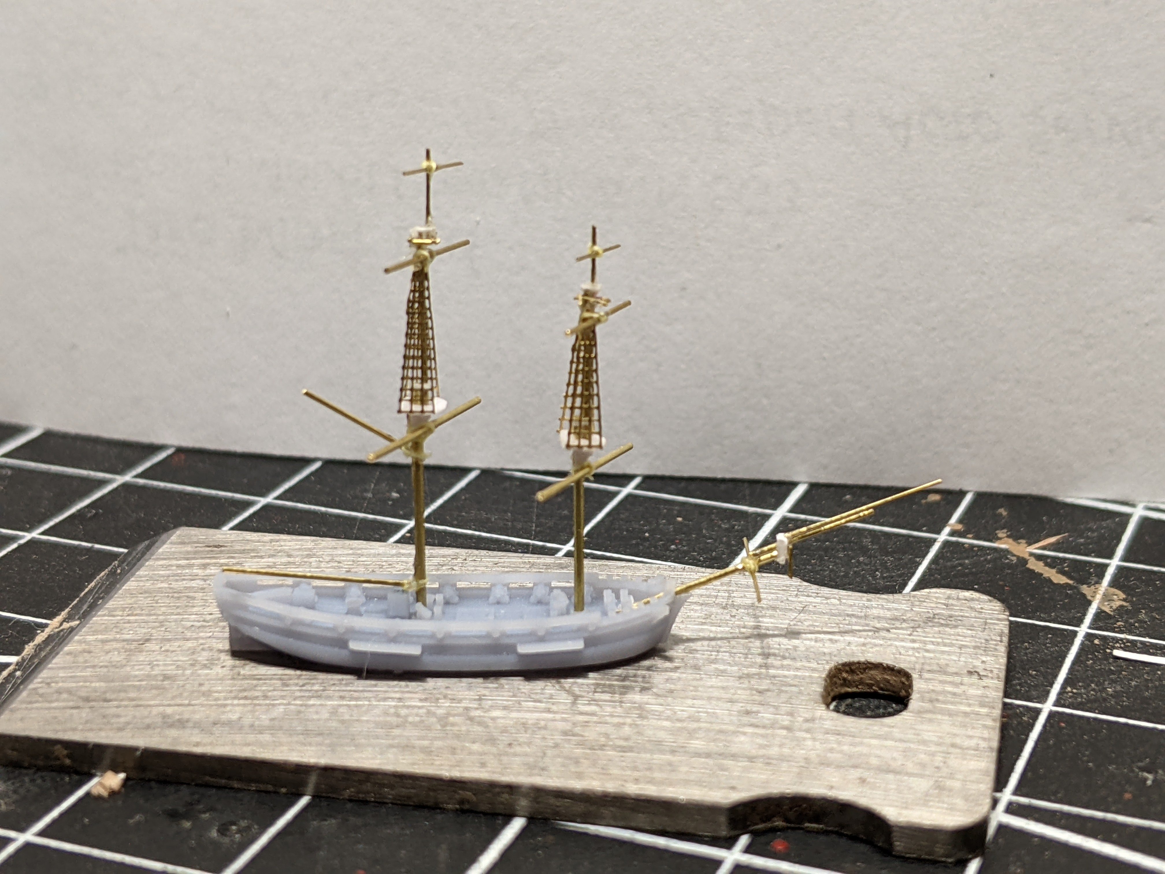
1/1200 Vigilant Class Brig - The Yards
My work on the smaller scale continues and today I am going to discuss the yards.
Unfortunately I don't have much in the way of pictures because taking them in the middle of building is really difficult at this scale. So instead I am going to use some diagrams to demonstrate and then show a picture of the finished product. First I took a look at some maritime paintings to pick a sail layout. It is important to plan out exactly what you are planning to do as this will impact the position of the yards and we want to produce a coherent model.
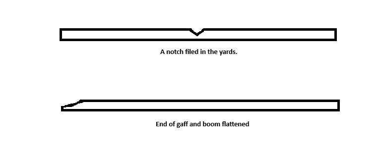
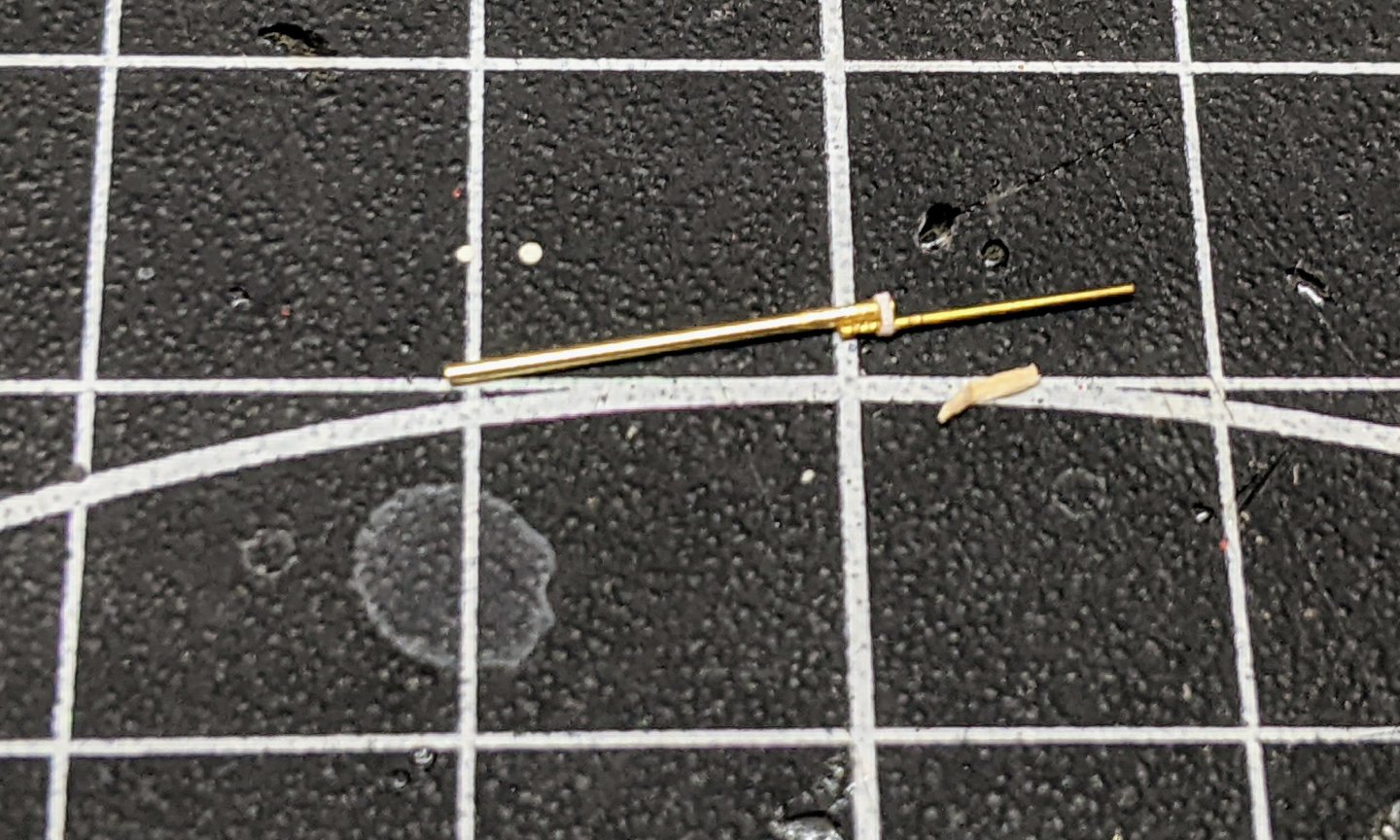
After cutting the various thicknesses of brass rod to size, I filed a notch in the middle of each yard to help hold it in the right place. For the gaff and the boom, instead of a notch I used a pair of plyers to squeeze flat one end.
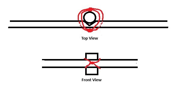
I then super glued the yards in place and tied them to the mast with 10/0 fly tying thread. Though this is not a perfect solution, I have found that this is the best way (where I don't have access to soldering) to secure them to the mast and better to do it now then have them constantly falling off while painting. As you will see in the final picture, it is not really noticeable. I first do a single knot at the front and then run the thread under the opposite sides of the yards from which it came and do a single knot secured with super glue at the back. Then after it is all dry I cut off the ends with a fresh scalpel blade.
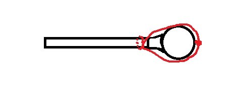
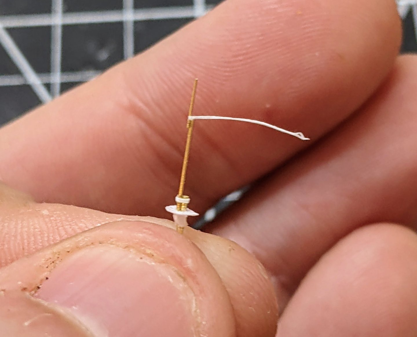
For the gaff and boom I used the flattened area which was now a bit wider to tie on with a single knott (and secured with glue) some more 10/0 fly tying thread. The ends of this were then tied around the mast and both the connection and the knot secured with glue.
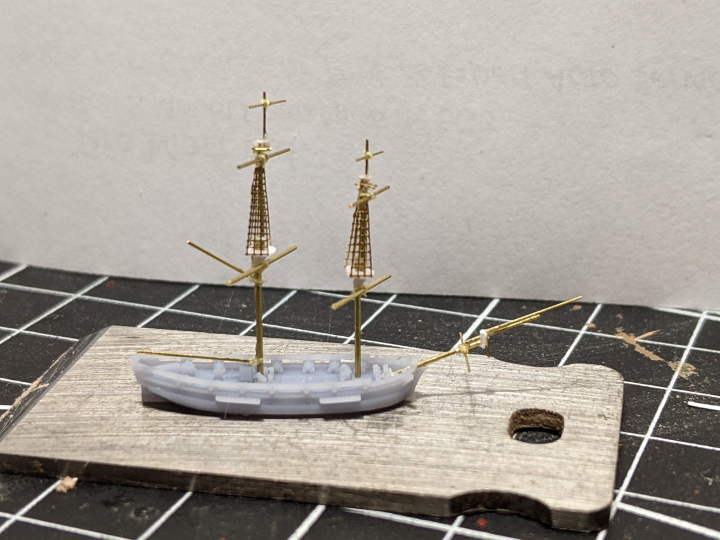
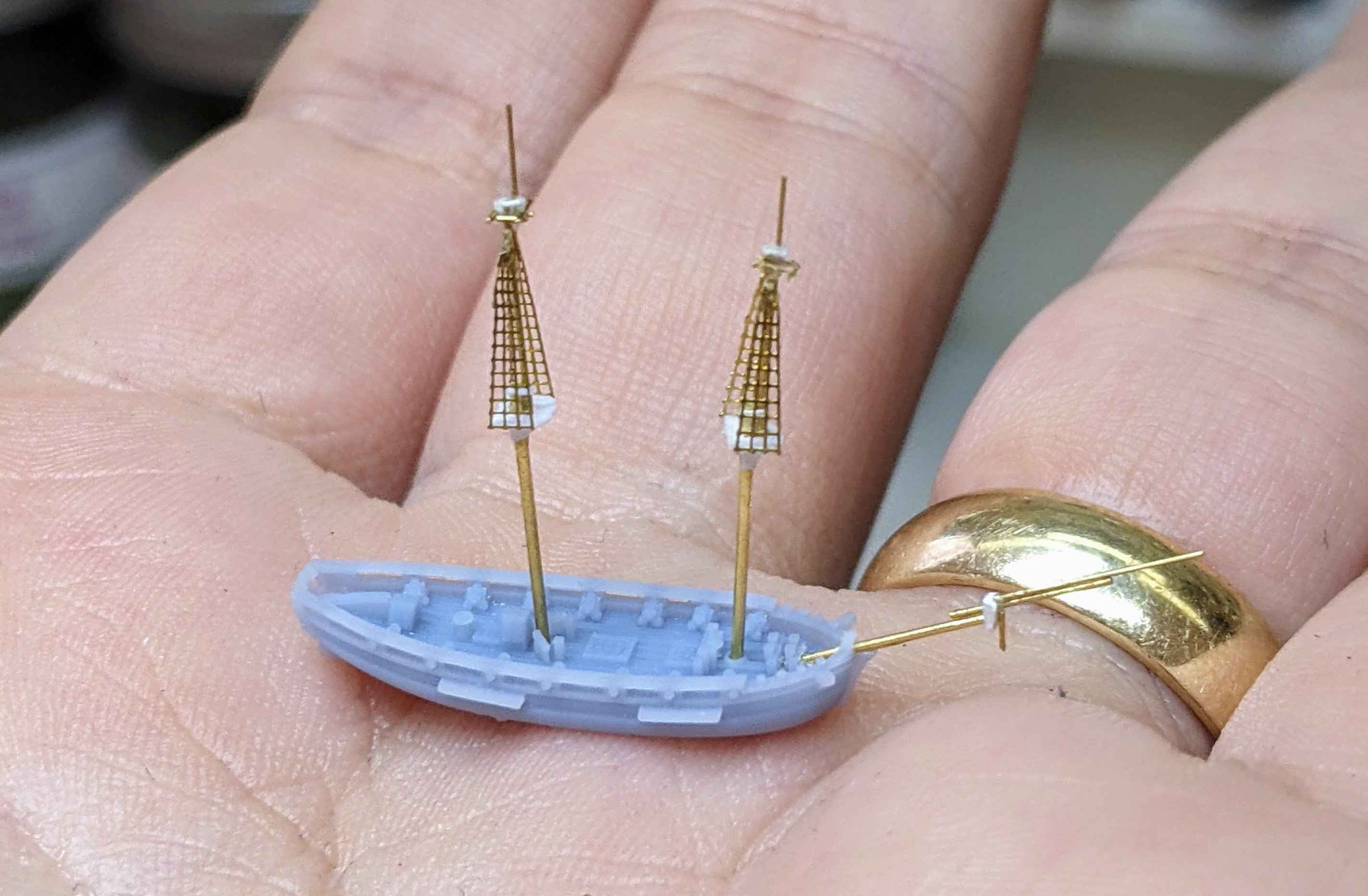
And here is the finished product ready for basing. The masts are only loosely in place as they will be painted separately before being attached once I have finished painting the deck details. I have chosen to depict her broad reach with the wind on her larboard beam.
- JacquesCousteau, ccoyle, archjofo and 3 others
-
6
-
This is a very cool construction method. It is looking like it will turn into quite the model.
-
56 minutes ago, Sizzolo said:
Do you have any references for narrower ones?
Not really, th only thing I have is the contemporary model of bellona which shows a very narrow batton.
https://www.rmg.co.uk/collections/objects/rmgc-object-66299
Apart from that it is just what I see most people doing. It is one of those things I never bothered to ask if it was done another way.
-
2 hours ago, Sizzolo said:
Battens next to protect top row of copper plates…
Your batten is much wider than what I normally see (it is basically another plank on top). Normally people only use a thin strip. Did you find something in your research suggesting they should be wider?
-
A bunch of the contracts from the late 18th century mention the lead as well. Fore example here is the wording for Perseus 1776:
Quote
To lead the gripe with thick lead 12 lb to the foot square, to lap on each side 3 ½ in buried in a rabbet fastened with proper nails, their heads depth in lead & to run from 4 ft abaft the end of the keel, and so high as to be above the range of the cables, the ends to be let into the hood and well fastened.I am still considering if I want to show the lead or not. We will see. I may just wait till the time comes and see how it matches the aesthetic I am going for. What did you use for the lead, actual lead foil?
-
Looking good.
I am also finding courage to start on parts can be a problem. You put all this time into them and practice, but taking the step to start on a finished part feels very dangerous :).
- cotrecerf and jpalmer1970
-
2
-
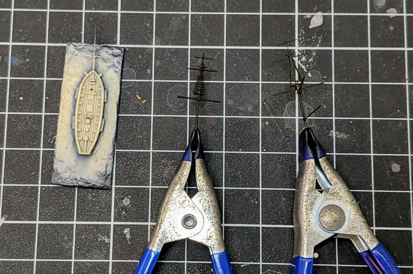
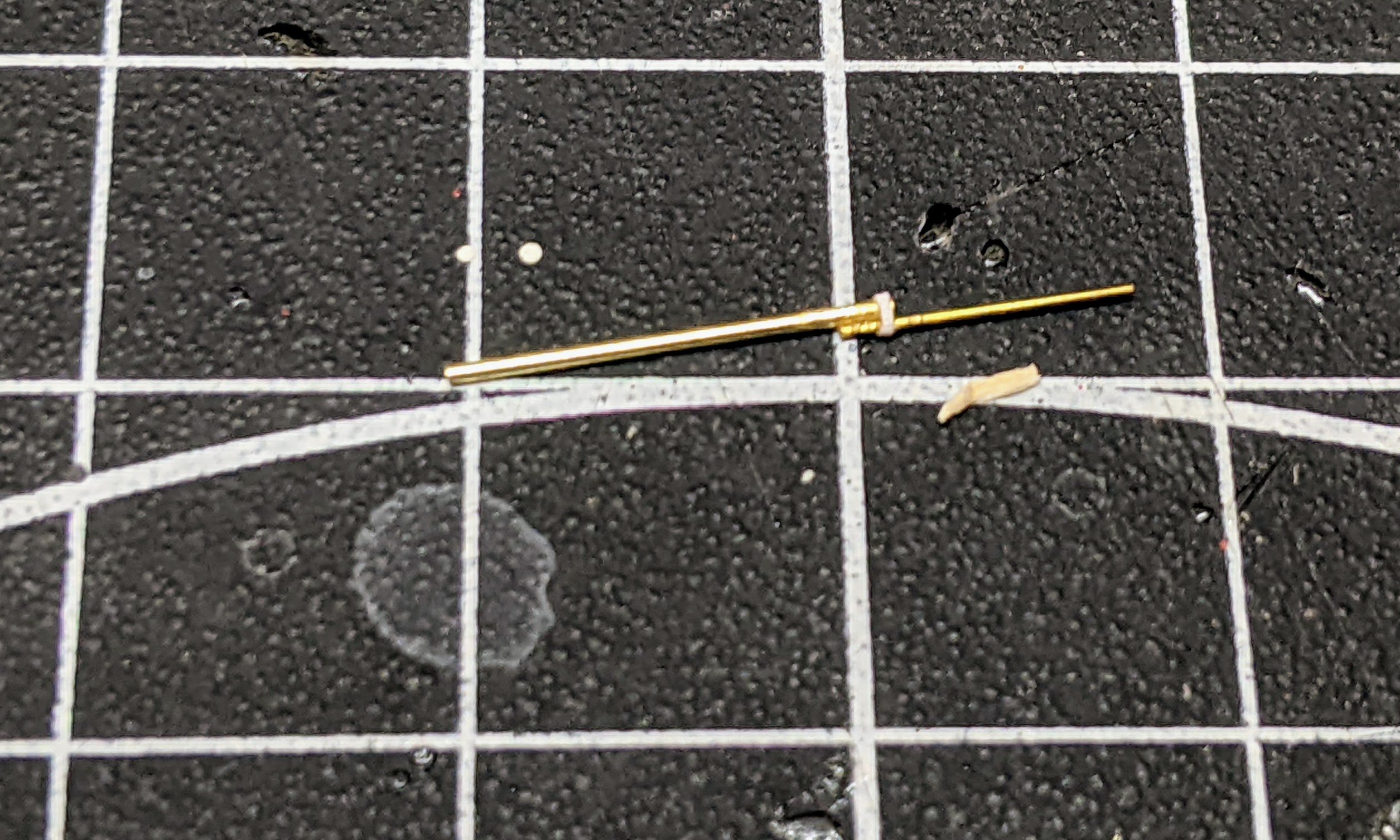
1/1200 Vigilant Class Brigs - Masts Continued
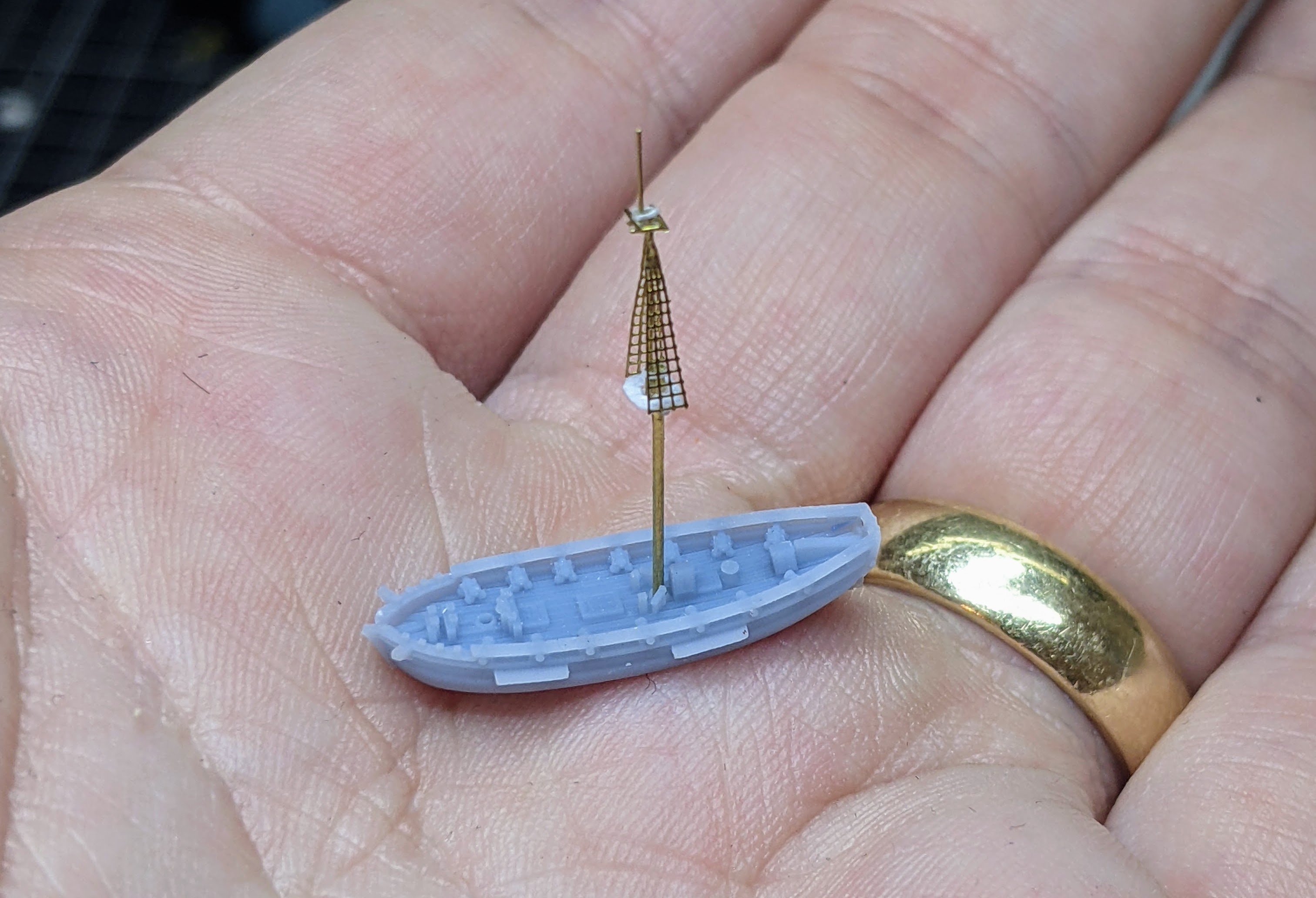
I have managed to finish the masts and so figured I would try to show a little more of the construction method. I apologize in advance for the not very good pictures, but it is actually harder to get good in progress pictures at this scale than it is to actually construct the masts. I am going through the fore mast in this particular case, but the process is pretty much the same for the main and the bowsprit. For scale reference, the squares on my mat are 1cm.
Step 1 is to cut the necessary lengths from the various brass rods. The lower mast and the topmast are glued together then a thin strip of printing paper was cut and glued around the joint to simulate the mast cap. This also has the effect of greatly strengthening the joint.
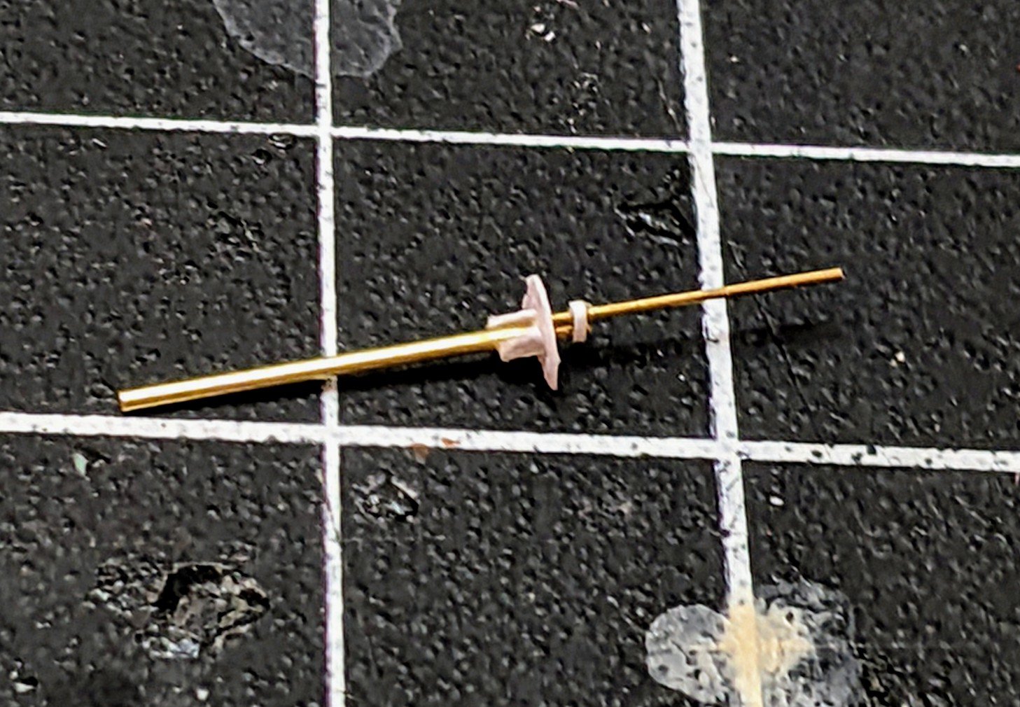
Next I took some slightly thicker drawing paper I found and cut out the fighting top. This was tacked in place with glue and then the the support structures (I don’t know what they are called) also glued below. Once everything is in the right place I cover all the paper pieces with a thin layer of super glue to strengthen it.

Then I move on to the topgallant and glue it onto the topmast. I should note that I find at these small scales that you have to be a bit flexible with the sizes. I only have so many sizes of rod to work with and it is more important that thicker masts look thicker than that they are the exact correct size. So in many cases I adjust the sizes to allow for example the bowsprit to be thicker than the jib which in turn is thicker than the flying jib even if that means scaling up the thickness a bit.
The below picture also shows the process of wrapping the paper round the joint to simulate the cap. First I tack then end to the joint and once it has dried I cover the area with glue and wrap the paper around.
And here is the current state of affairs. All the masts are done and now I need to move on to the yards. For the fore mast I found a way to get the trestletree to have three pieces sticking out. I just used an off cut piece of the shrouds to simulate the structure. I think it turned out good and will probably use this method going forward.

-
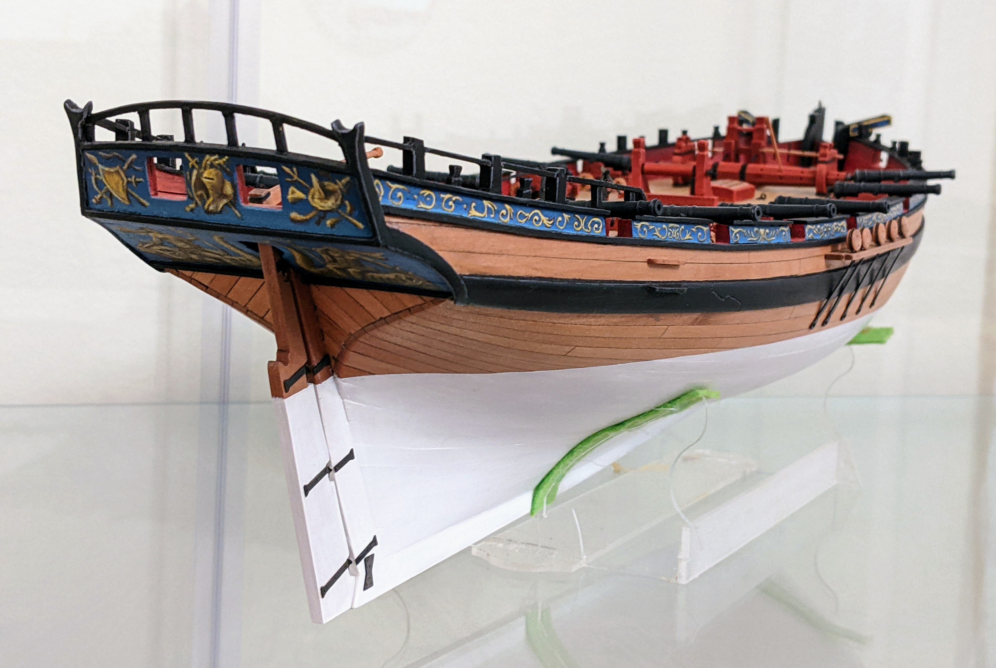
1/1200 Vigilant Class Brigs - Masts
I have not posted here in a while as I have been wrestling with a problem I have with my 1/700 models. The issue is that they are probably too big.
I have been looking at various rulesets and playing around with the cutter models and have come to the conclusion that ideally I would like to play at a smaller scale to allow for more maneuvering space (given my play area is limited to my dining room table). So this has sent me down a rabbit hole of experimenting at smaller scales.
Having got my friend to print a few of the brigs at 1/1200, I have been playing around with how I would go about modelling them. The issues are mostly with the masting and rigging. I am confident that I can handle painting at this scale, but the masting and rigging is less certain. When you go smaller there are some advantages. You can omit some details or approximate them a bit as no-one is going to be able to look closely enough to notice. So after playing around a bit I cot some more sizes of brass rod and made a test mainmast.

You can see here that the model has printed well and that all the detail is visible. The mainmast is made with 0.5mm brass rod. It really should be 0.4mm given the scale, but I wanted to give it a bit more strength and accentuate the size difference between the lower mast and the topmast.
I used paper for the fighting top strengthened with superglue to hold it rigid. The mast caps were again wrapped with paper as I couldn’t think of a better approximation at scale. Though they are probably a bit oversized this will accentuate them when we come time to paint. The trestletree had to be approximated with only 2 cross pieces (as opposed the the three it should have).
The shrouds gave me a fair bit of pause. There are no good aftermarket versions available for 1/1200 scale and I did also consider simply using thread and omitting the ratlins. But in the end for both structural reasons (this holds everything rigid) and also ease (trying to get thread in the right place felt like it would be too difficult), I decided to go with my 1/600 shrouds I have. Though they are oversized, from normal viewing distances they actually look fine. In some ways the oversized nature helps to see the detail. I also have some plans when it comes to painting to simulate the deadeyes and lanyards.
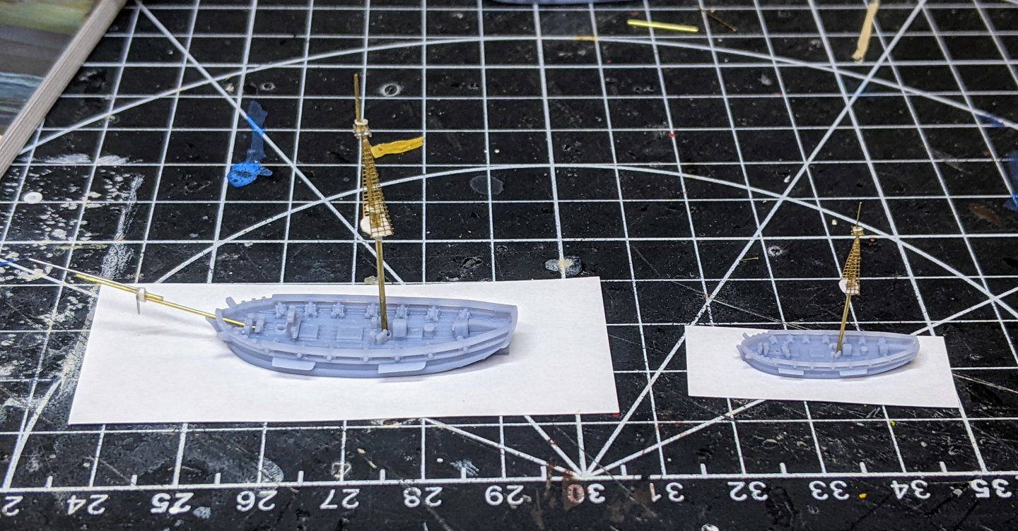
You can see below how much smaller this scale is compared to 1/700. Though it is about half the size in length, in terms of area is is about 1/4 of the size. You can also see how much smaller a potential base size is giving much more room to maneuver on the table. The 1/700 version is about the size of a large frigate at 1/1200 scale.
So that is all I have for the moment. I am going to build the foremast and the bowsprit next and once that is done I will move on to the yards.
-
57 minutes ago, Pitan said:
Looks like good progress.
Off topic, I'm intrigued by your scenic materials (I think), and, (maybe) figure armatures in the background of your last photo.Thanks,
Not much to see with the materials. From left to right they are various static grass, various sands (light to course), rocks and fake moss, cork, bark.
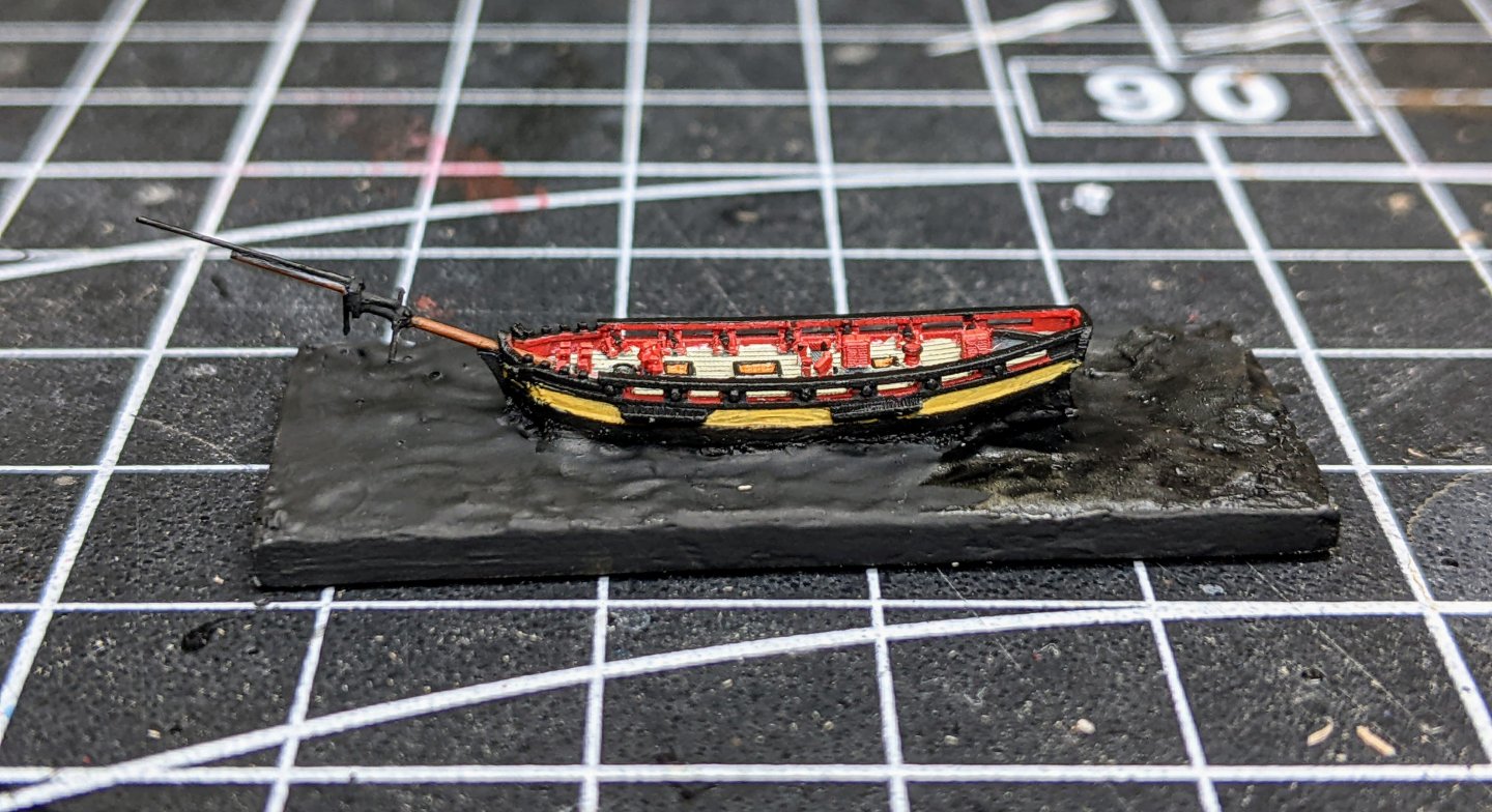
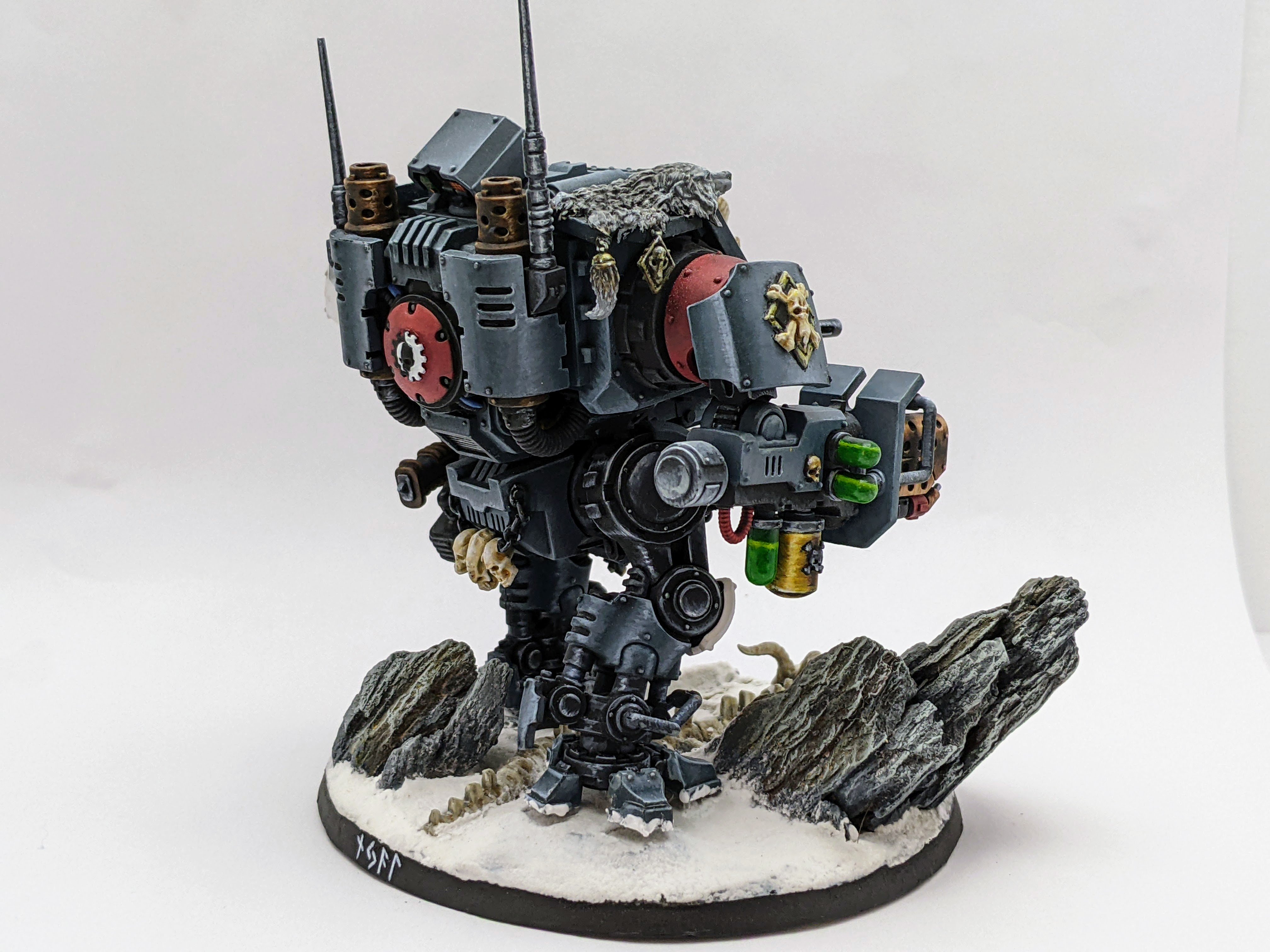
The bark does a good job of simulating rocks for miniature bases. For example see the below model.
The model pieces you can see in the background are masts for my small scale Napoleonic ship miniatures project. You can find a link to a build log in my signature.
-
Congrats on a lovely model.
-


HMS Perseus by Thukydides - 1:64 - POB - Sphinx Class 6th Rate
in - Build logs for subjects built 1751 - 1800
Posted
Log #20: Bolts, Joints & Corrections
Thanks @AON for your suggestions. I have done a bunch more research on the subject of tapering the knee of the head and found some interesting things. I will post some of my findings next time.
As research is ongoing in the background, I have continued to work on the bow and the keel. When I last updated you all, I had almost finished assembling the knee of the head. The next step was to glue the last piece in place and then make corrections to the overall shape. Overall the process has been better than anticipated in terms of wastage. I have only had to remake around half of the pieces. Most of these remakes were due to silly errors (I didn't think before cutting) as opposed to improper fits.
I had purposely left some leeway on the outer edges to allow for corrections once everything was glued together. As I am clamping at high pressure to make the joints as tight as possible, I anticipated there might be some slight bending of the pieces and so stuck a template of the overall shape in place to make adjustments with my drum sander.
Once those adjustments were done, it was time to drill the gammoning and bobstay holes. I stuck templates of the individual pieces onto the finished piece to get the positioning right. Then I drilled the holes with my drill press. For the gammoning hole I simply drilled the two ends and then used a combination of min chisels, scalpel, files and sandpaper to open of the rest of the hole.
Using my mini chisels I cut out the various joints. For the keel joints I am not scarping them correctly as no-one will actually see any of those joints except the ends butting against each other. I considered simply just butting the ends together with no joints (where you can only ever see one side at once, but my OCD rejected that. You can see how I have written the part number and the direction that faces forward on the top of the pieces. Remember when I mentioned having to redo pieces because of silly mistakes?
As previously noted I glued pieces together using a 50-50 mix of heavy body acrylic paint and wood glue.
Then I glued the lower stem into the fore piece of the keel and then clamped and glued that assembly to the knee of the head.
The order here is important because I need a square surface for drilling holes and so as I add thicker pieces I need to be aware of what holes need to be drilled where.
For the bolts I discovered that the black 18lb fishing line that I had left from when I used it for bolts on alert was pretty much the exact right size for the 7/8 in bolts called for by the contract. So I drilled the holes with my drill press and glued the line in place using super glue. Note that I just drilled half way and then flipped the pieces over and drilled with a new template from the other side. Any small deviations could potentially be really noticeable so I figured safer to do it this way.
You can see below the line sticking out of the holes as the glue dries. Note that I have not completely cleaned up from the gluing process as there is lots of sanding to come which will fix any glue residue still on the outside.
The final thing to note is a realized something today that I am glad I caught this early (before it became a problem). The plans I bought seemed to indicate that the waterline on the model was parallel with the keel, but when I went back and checked the various sphinx class plans, I realized that all of them show the waterline as having a small keel drag. At first I thought this might be a distortion issue, but it is remarkably consistent and pronounced across all of the sphinx plans. This does create some future problems for attaching the model to the base as I made the screws perpendicular to the keel, but the slope of the waterline is only very slight and so I figure I can probably come up with a way to adjust for it.
Thanks for stopping by and for all the encouragement.