JacquesCousteau
-
Posts
1,067 -
Joined
-
Last visited
Content Type
Profiles
Forums
Gallery
Events
Everything posted by JacquesCousteau
-
 Very cool! I have vague memories of having seen the Alma over a decade ago, although at the time my interest was more drawn to the larger ships in the museum. What a missed opportunity! Noting the curved sides of this model, I feel like it looks a little less like the Alma, which has very straight sides, and a bit closer to the Robbie Hunter, plans of which are in Chapelle's National Watercraft Collection book. Although I don't know how the scale would match up. Another source you may want to look into is Roger Olmstead's "Scow Schooners of San Francisco Bay". It may be available as an interlibrary loan. I know there are a few articles on scow schooners available from the Nautical Research Journal, too.
- 33 replies
-
- 1
-

-
- San Francisco Bay Scow Schooner
- Scow Scooner
- (and 1 more)
-
Thanks, all! It's great to know that I inadvertently made something more accurate than I thought, how often does THAT happen?
- 281 replies
-
- 4
-
-

-
- Chile
- Latin America
- (and 5 more)
-
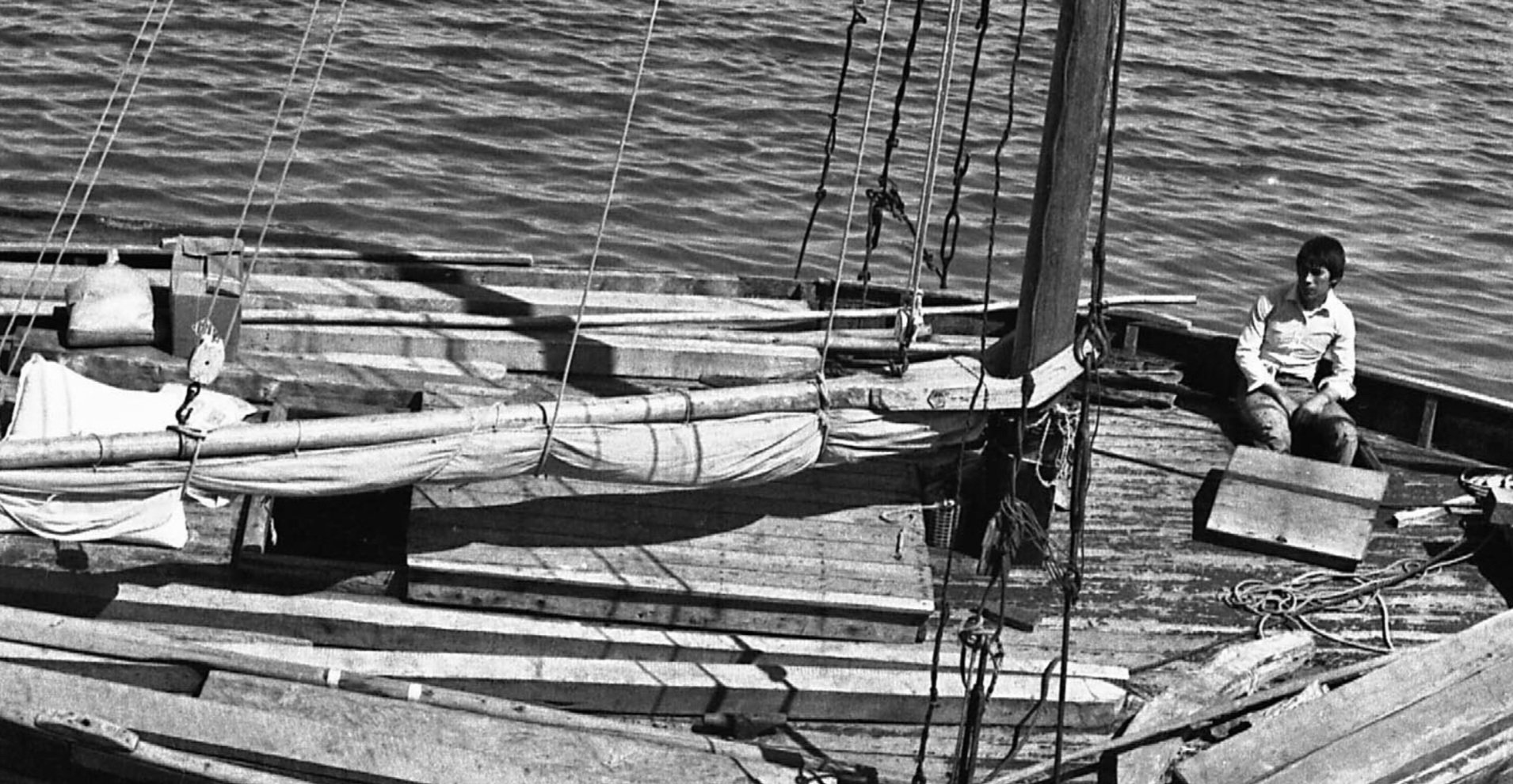
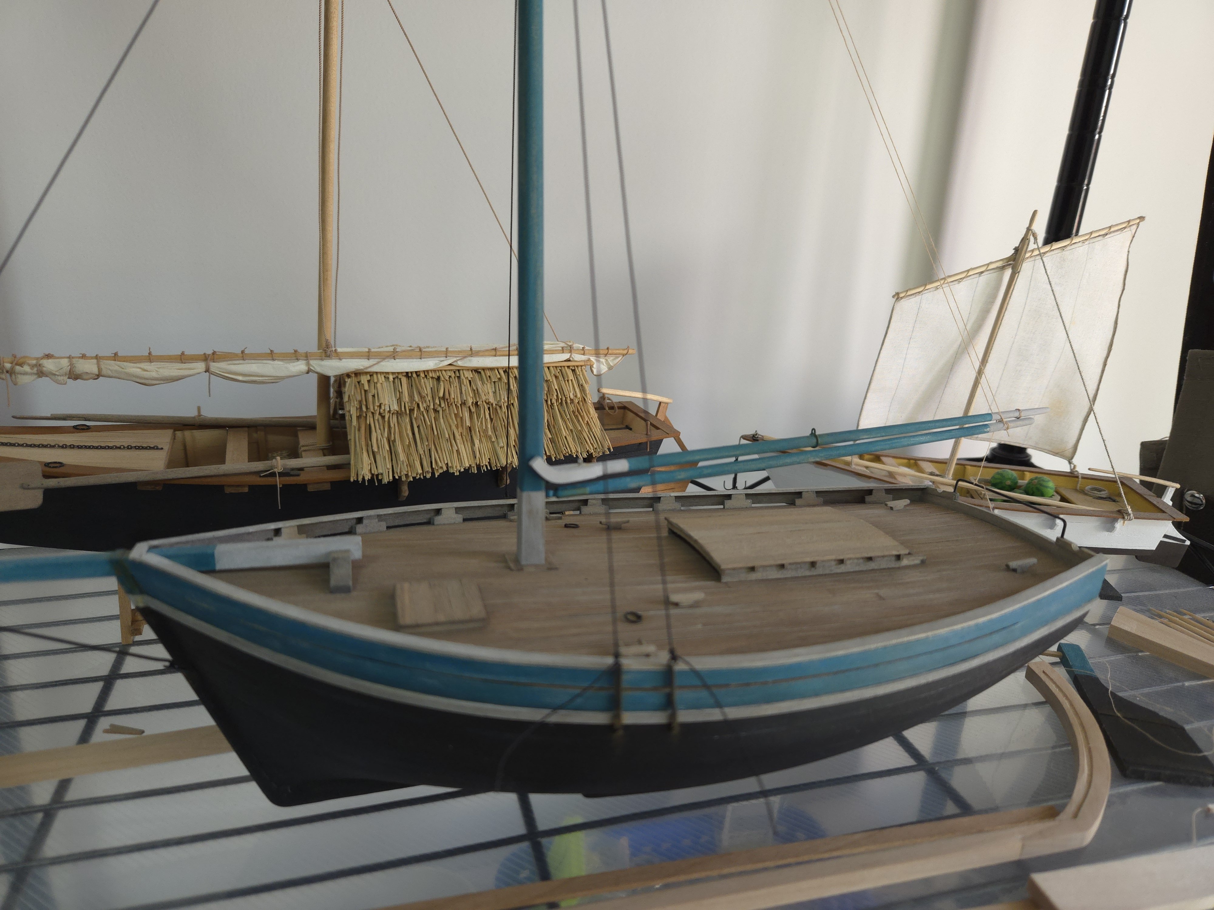
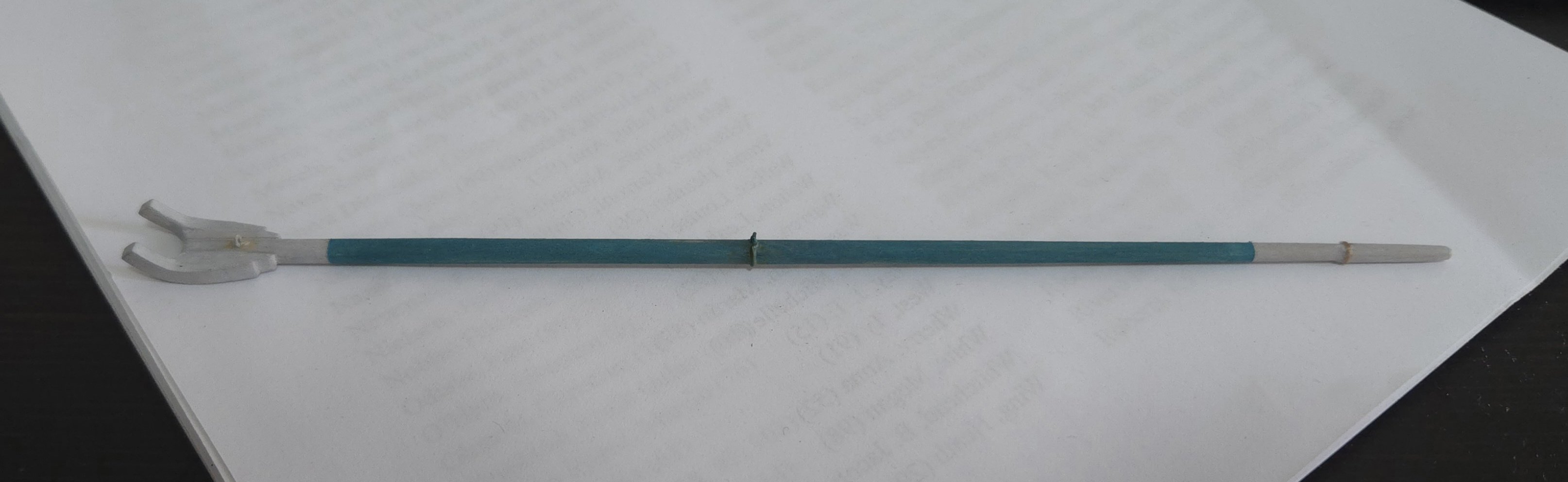
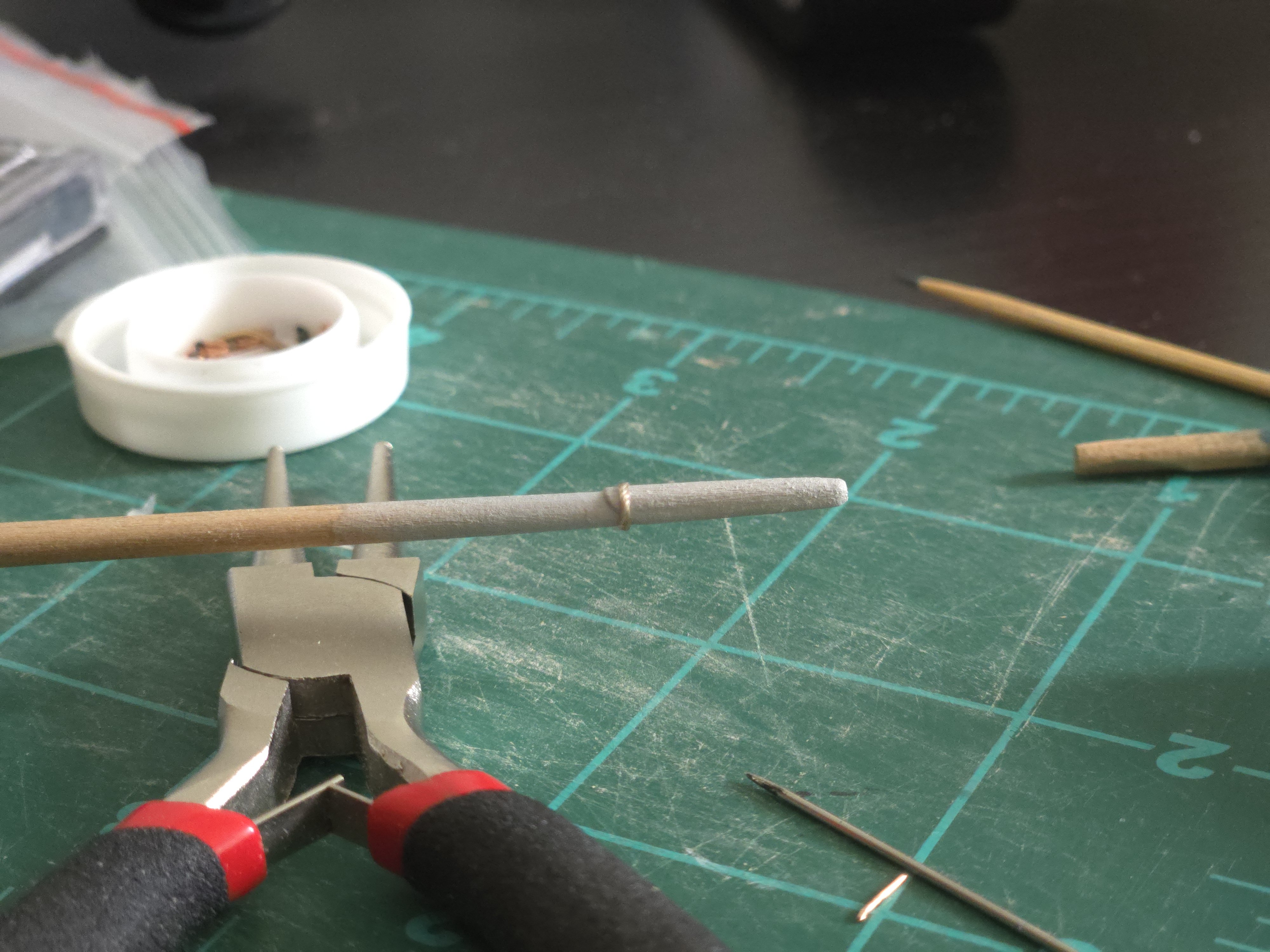
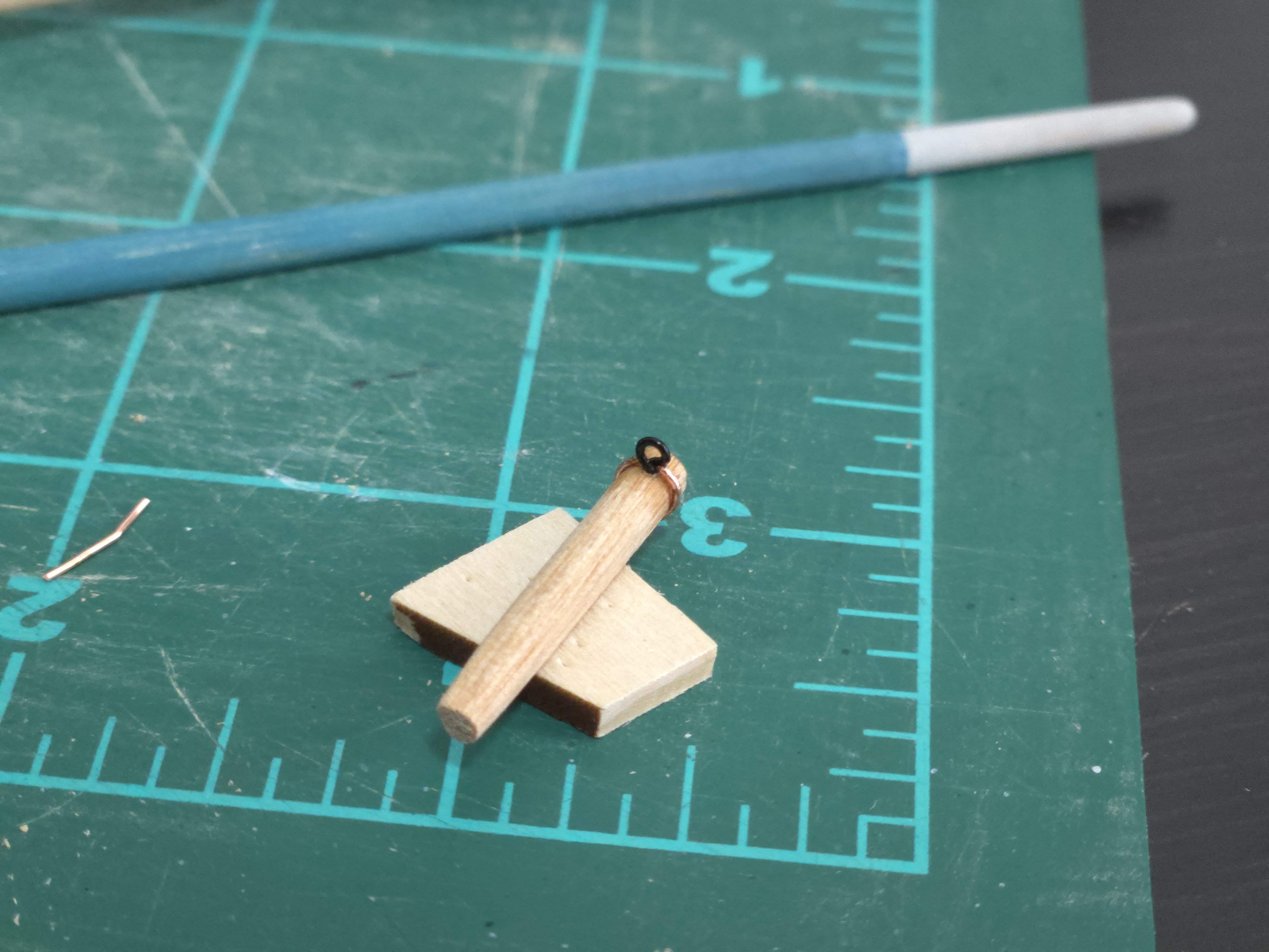
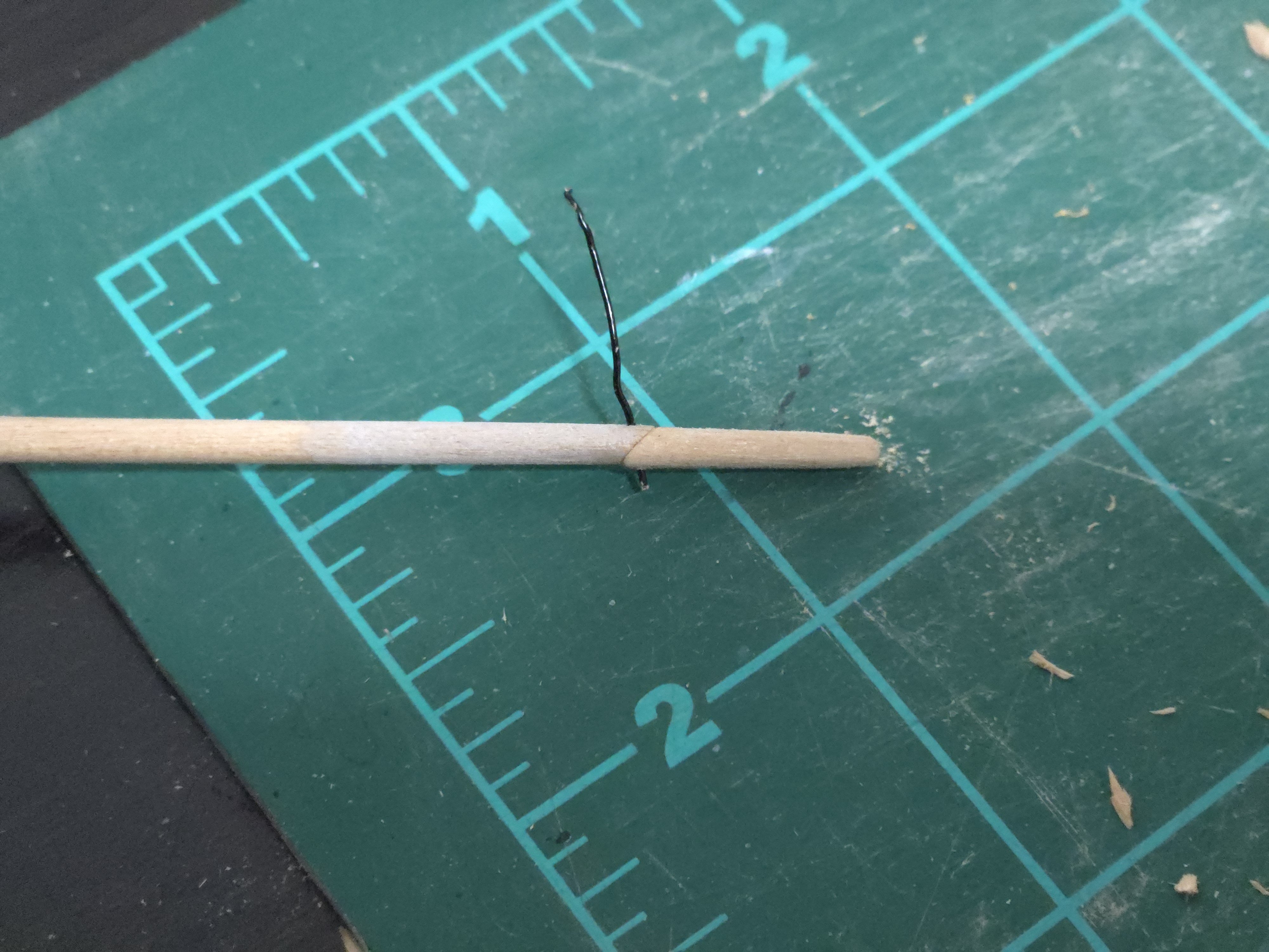
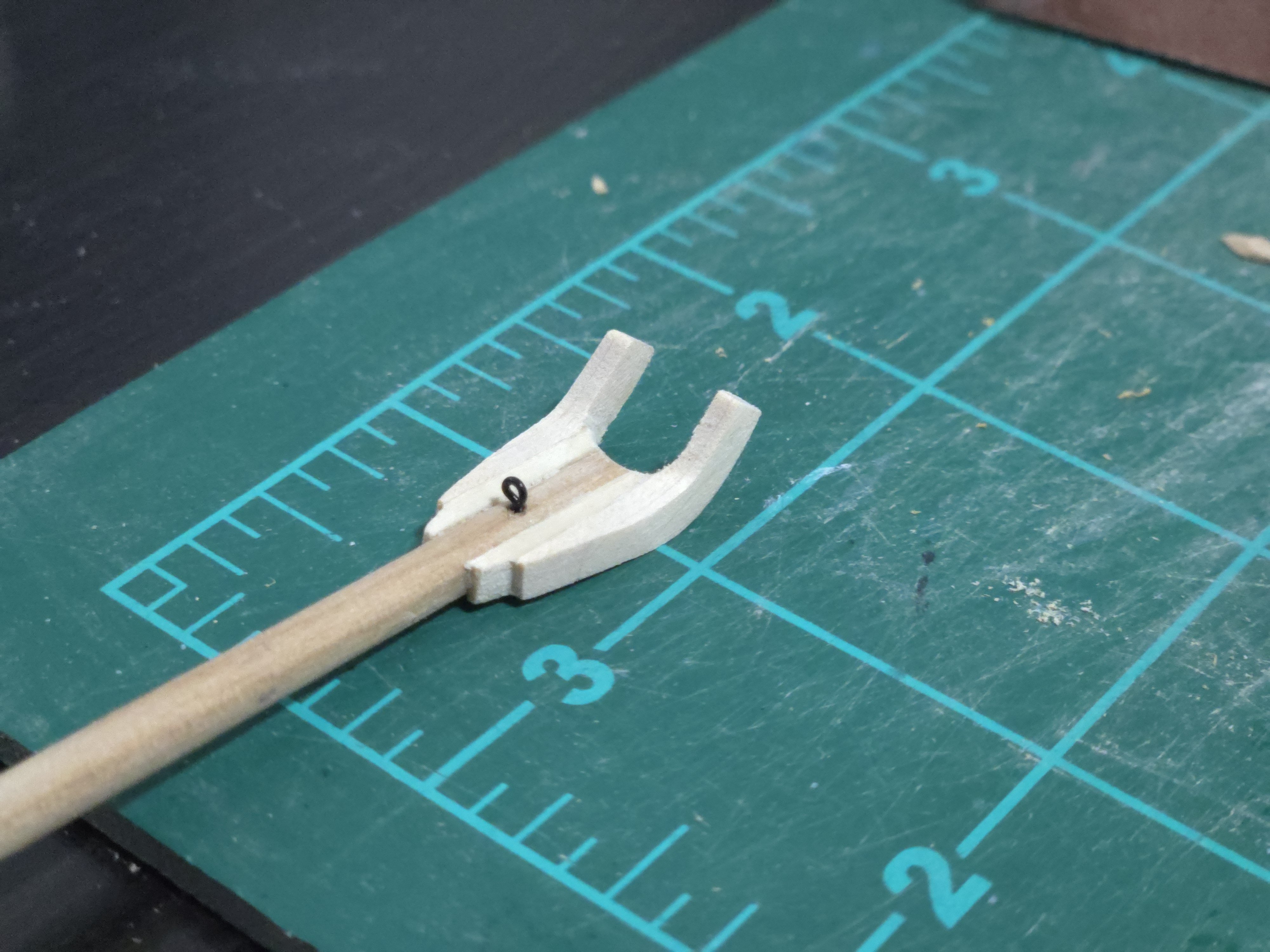
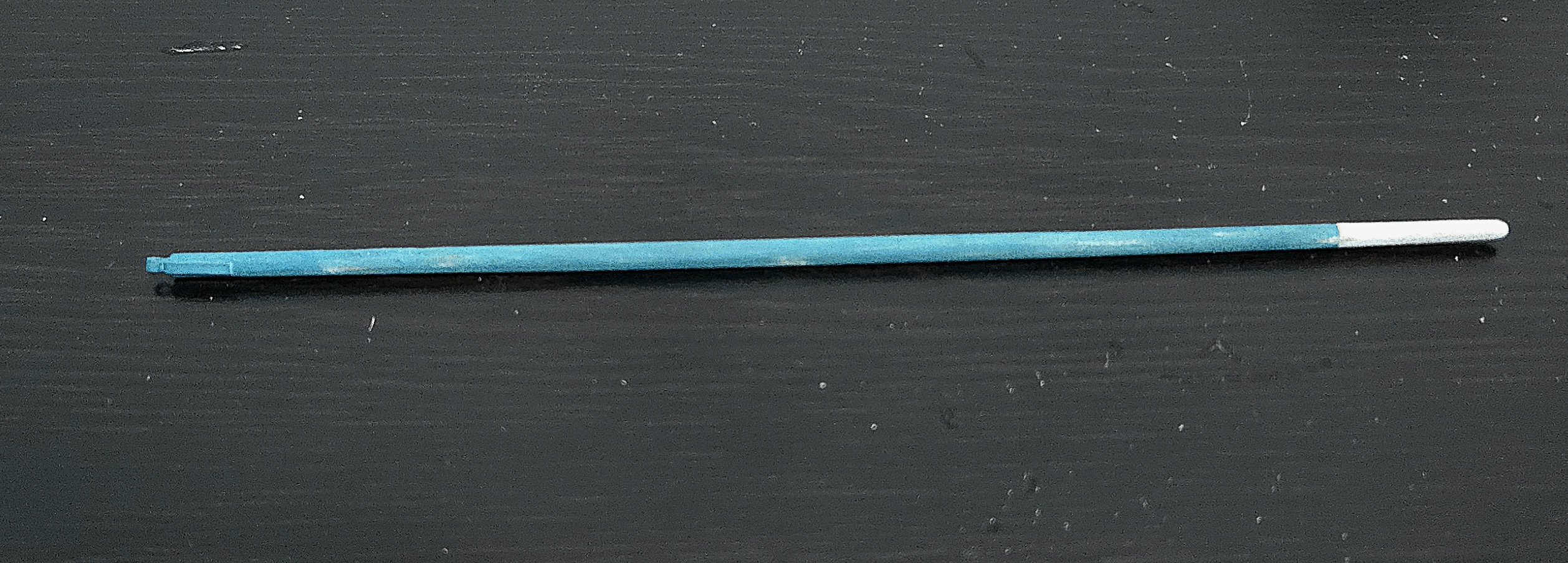
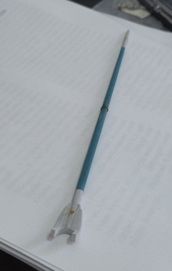
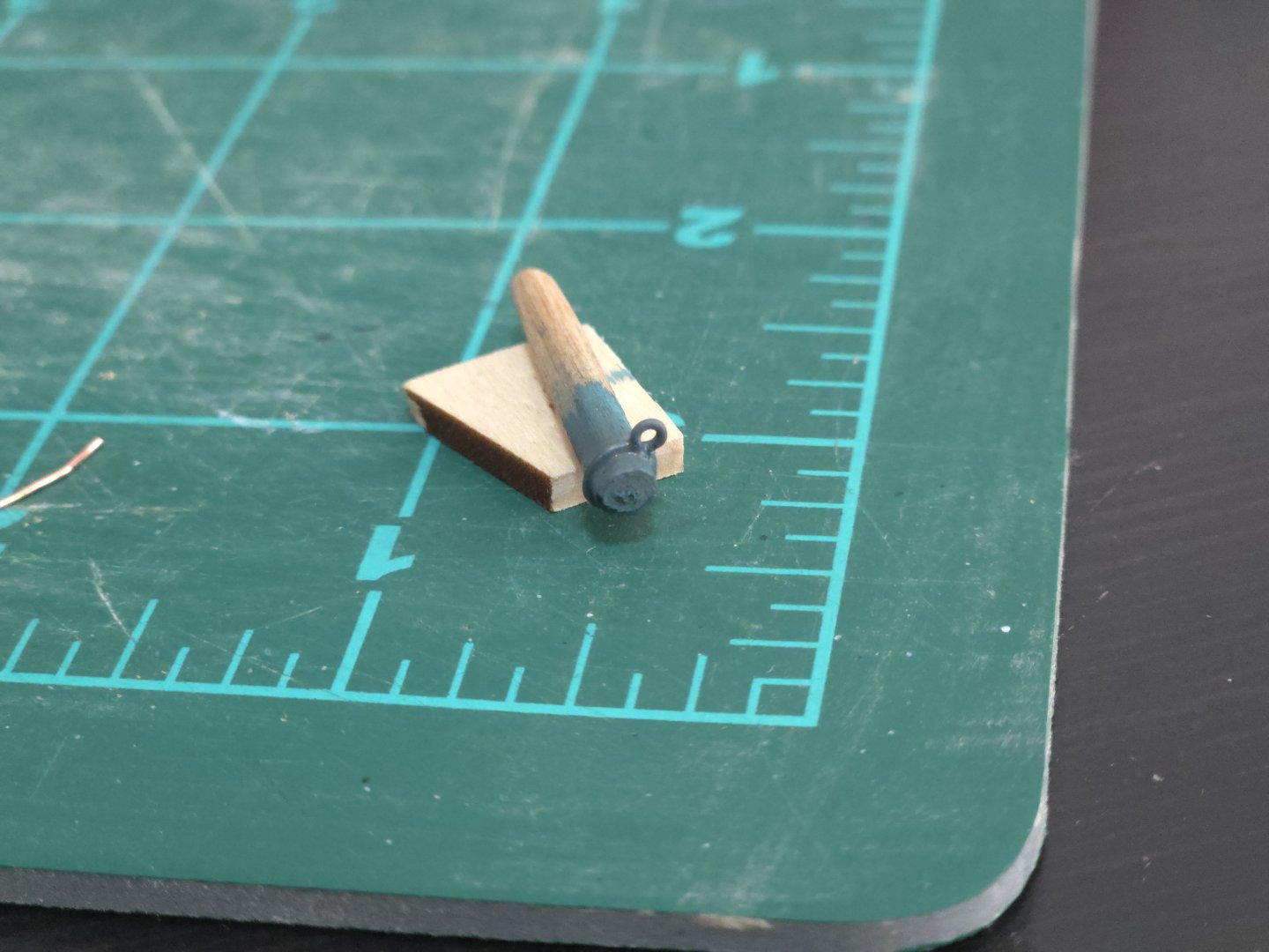
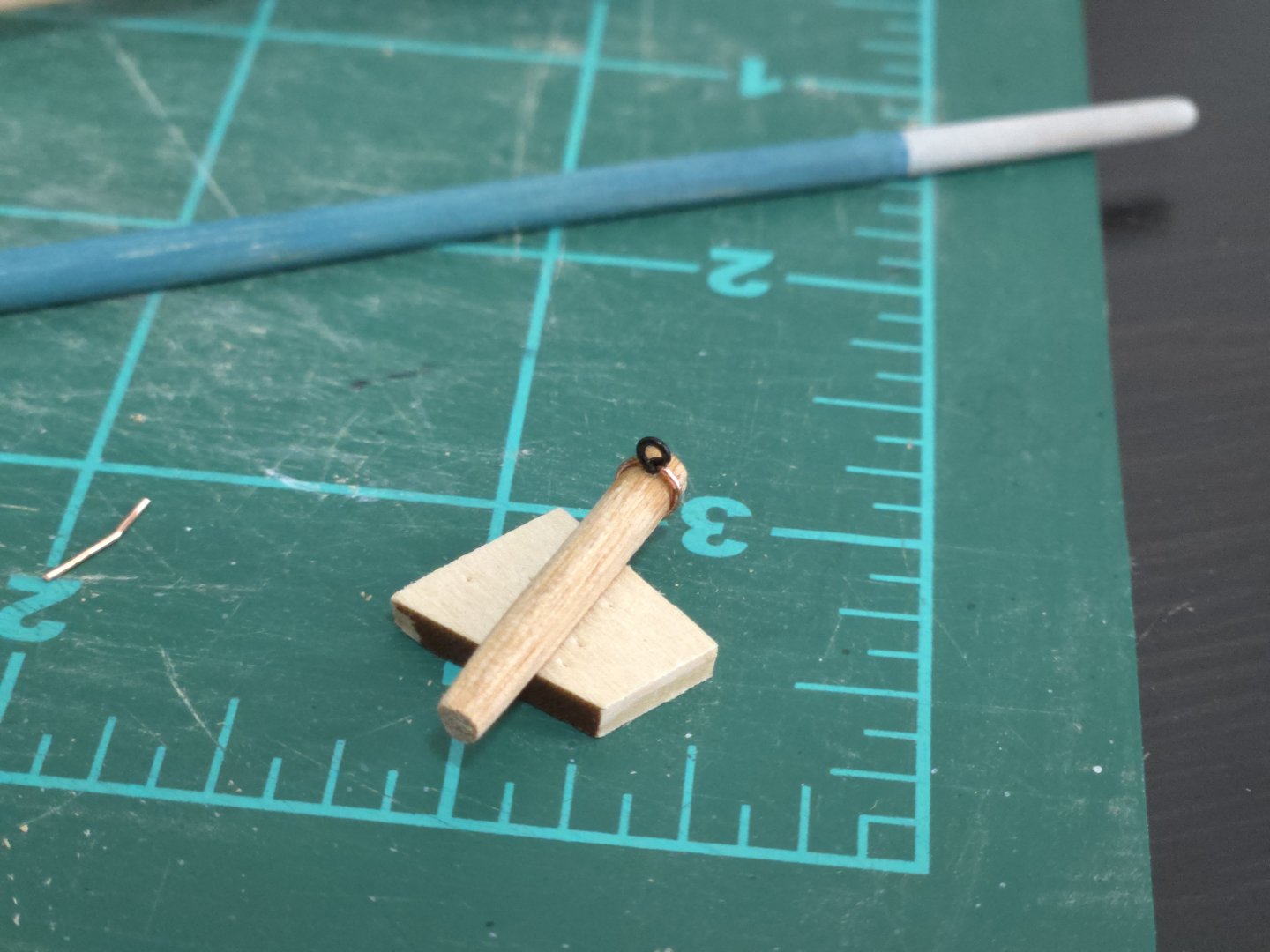
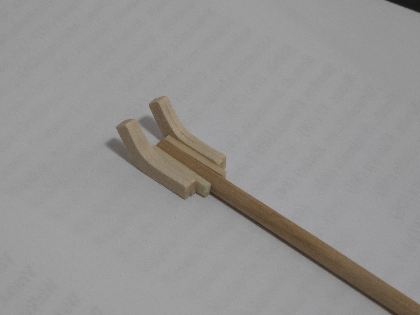
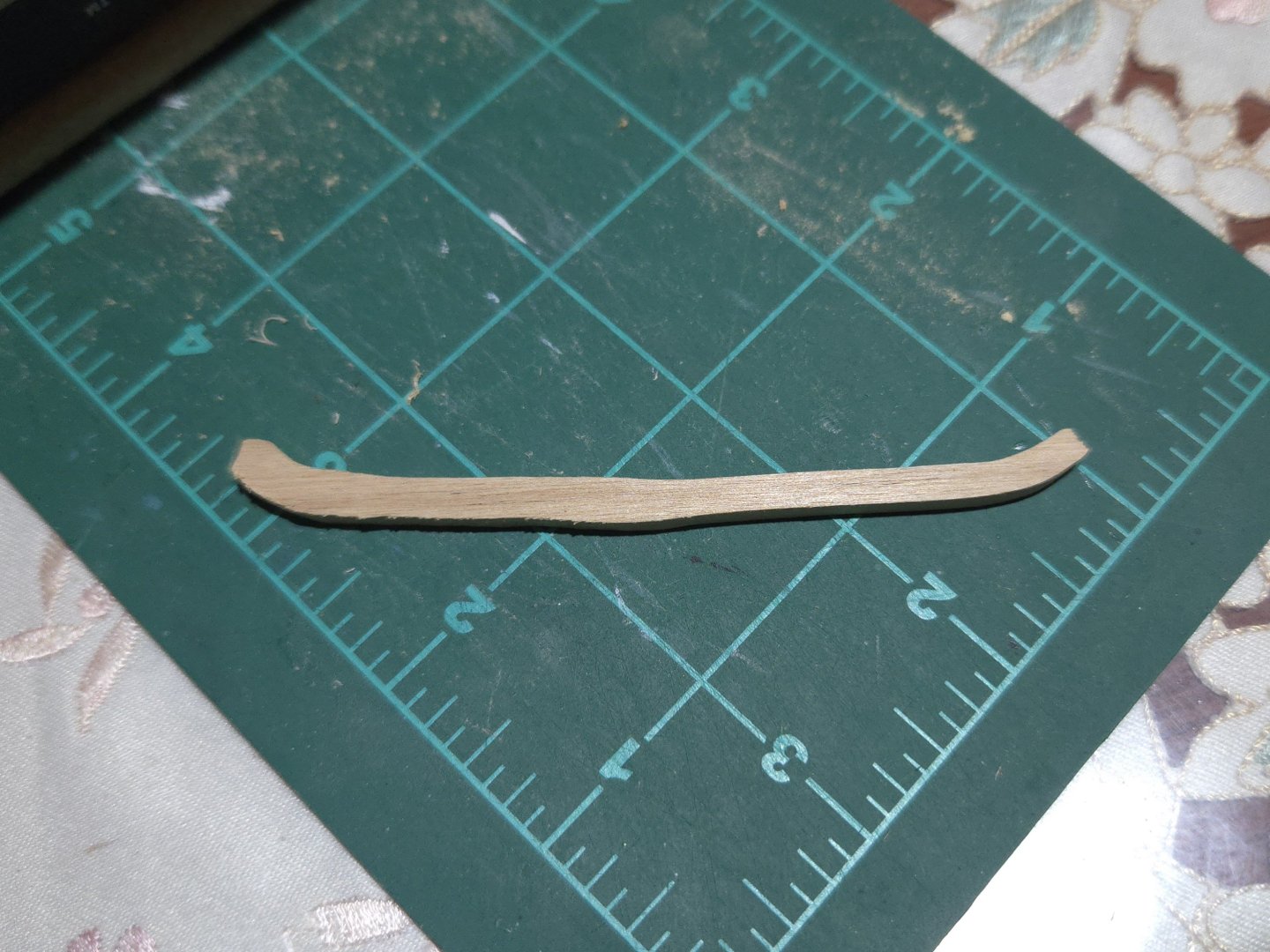
It's been a little while, as I was traveling and then had a very hectic week and weekend, but I've made a bit more progress. When I left off, the boom had been made but was unpainted, and I had made a new spar for the gaff. I first painted the boom. Initially I wanted to have gray-white at both ends, but the thin gray I was using had a very hard time covering the primer I sprayed over the metal gooseneck at the fore end, so I ended up only adding gray at the aft end. On the gaff, I needed to fabricate jaws that would not just wrap around the mast, but curved upward. Most lancha photos that I've seen had upward-curving jaws, although a few had flat ones, but I think the curve looks nicer. An example is shown below; I particularly liked the "stepped" design of the aft end of the jaws. Source: https://www.flickr.com/photos/luchinmardones/5232587713/in/album-72157625422798225/ It took me a while to figure out how to best handle this. Rather than carve the jaws from a much thicker piece of wood, which seemed like it would be very challenging to get even, I decided to build them up from multiple layers of easily-cut 1/16‐inch basswood sheet. I made them a bit oversized, as seen below, in order to sand and file them into an even final shape. A lot of shaping later, and I had jaws I was happy with. I also added the eyebolt for the throat halyard block. Meanwhile, I wanted to replicate an example of a lancha where a small extension had been added to the end of the gaff, either to repair a damaged tip or as a post-hoc effort to change the sail shape slightly. (The photo, which is of the lancha Quenita, is shown in a few earlier posts). To do this, I cut the tip and a bit of scrap spar at a 45-degree angle and glued them together. I then drilled a hole between them and threaded a bit of wire through to strengthen the joint, shown below before trimming the wire: I then painted the tip and added a small lashing. Finally, I needed to add the connection point for the peak halyard block. On some lanchas this seemed to just be a rope, but on many it was a metal ring, apparently with a small eyebolt on it (see the photo of a real lancha shown above for an example). Given that I don't have a soldering iron, or know how to solder, I wouldn't be able to make a closed loop, and I didn't want to make something weak as there would be a bit of pressure on it. I decided to get creative and fake it, drilling an eyebolt directly into the spar, adding a ring around the spar, and disguising the joint with glue and then paint. I tested it on a bit of scrap spar cutoff--below, you can see that the ring and eyebolt are two separate pieces. And after painting (just with primer). I was happy with the results and decided to keep with this method for the gaff. Finally, I painted the gaff, dry-brushed a dash of "rust" around the metalwork, and sanded and scraped the spar for a weathered look. Finally, we can see the gaff resting on the boom (which is held up by temporary lifts). I think I should still add a dark wash over the gaff and boom to tone down the gray-white a bit, especially at the jaws. The photo also gives a sense of the size difference between the lancha and the canoa(s). I should note here that I'll need to remake the gooseneck pin, as my initial brass rod one proved too thick once painted to fit through the eyebolts. I also attempted to make a convincing forward hatch prop from some scrap alder. However, it looked bad, almost immediately fell into the hatch and took a lot of time to fish out, and then disappeared from my desk (maybe I threw it out on accident?) before I could take a photo. Ah well, the next one will be better.


- 281 replies
-
- 11
-
-
- Chile
- Latin America
- (and 5 more)
-
Looks like a fun build! Adding a planked deck is a great idea, just don't forget to take into account the extra thickness/height when continuing with the build.
- 33 replies
-
- 1
-
-
- San Francisco Bay Scow Schooner
- Scow Scooner
- (and 1 more)
-
Thank you! Glad to hear you found my comments helpful, I'm looking forward to seeing how your own build progresses. Looking back on this build, I really quite like the kit and appreciate how it takes the time to teach an effective planking method, and builds into a great display, as well.
- 82 replies
-
- 2
-
-
- half hull planking project
- half hull
- (and 2 more)
-
Excellent job, the finish looks great! And good call on the color for the carbon fiber sections.
- 47 replies
-
- 4
-
-

-
- Annapolis Wherry
- Chesapeake Light Craft
- (and 1 more)
-
Very nice work, the hull's coming along great!
-
Nice work! Interesting overhang on the front of the deckhouse roof.
-
Nice job!
-
Hi Pablo, greetings from Mexico City. It doesn't look like Jerry has posted for a long time so I'm not sure if you'll get a response. There's a very detailed discussion of topsail schooner rigging at this thread: You also might look at the recommendations in this thread:
-
Very precise work! In the pucture showing the deck on the hull, are the bulkheads showing through the deck, or are the darker lines intentional?
-
Really fantastic job! To my eyes, at least, it still has plenty of quirkiness (in a good way). Hoping that all goes well for you!
- 732 replies
-
- 5
-
-
-
- Lula
- sternwheeler
- (and 1 more)
-
Thanks, all! I think that cardboard templates may be the way to go, as I suspect that I'll have to fiddle with things a bit to get the angles right. I may also try Paul's suggestion once I'm back from traveling, really anything that gives me a better sense of how this fits together will be helpful.
- 65 replies
-
- 5
-
-
- ancre
- Bateau de Lanveoc
- (and 2 more)
-
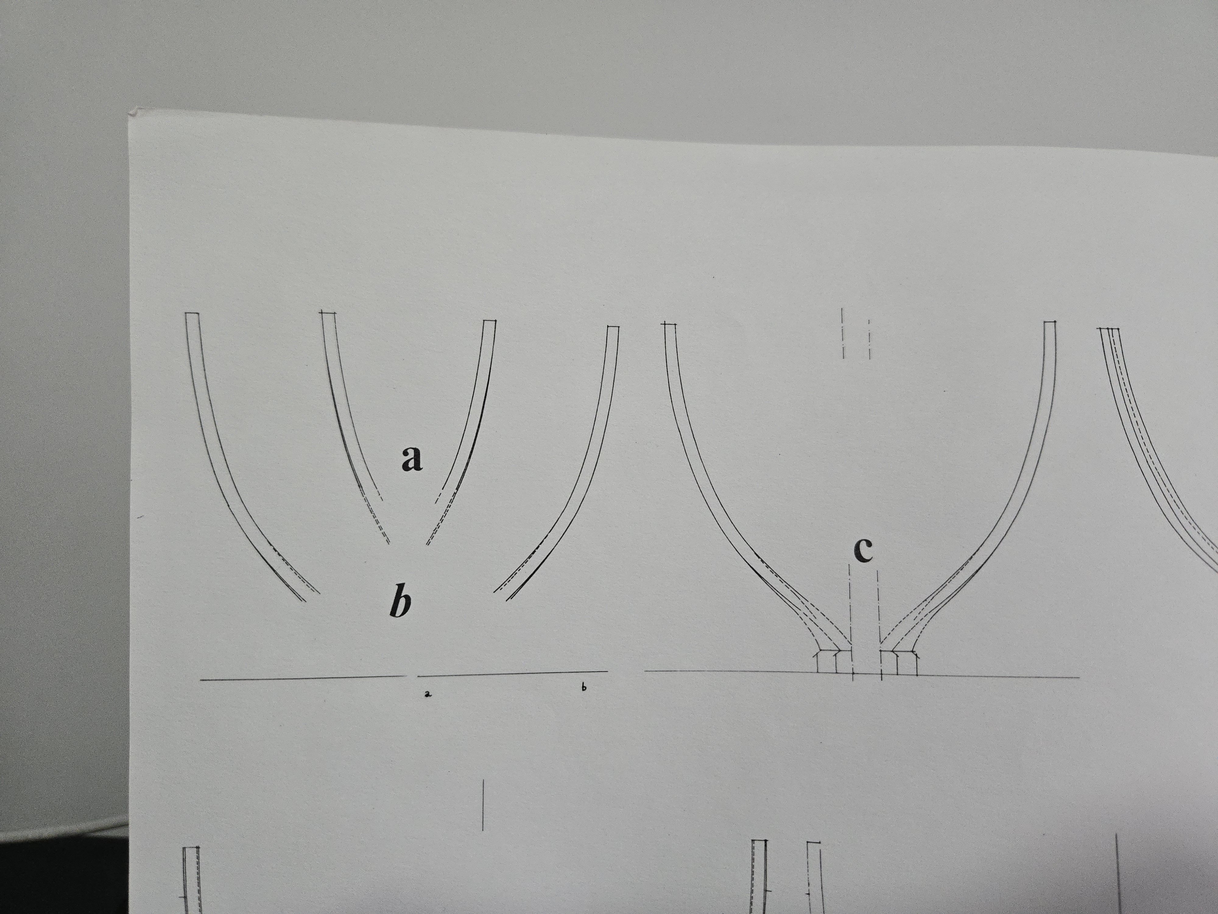
As I'm traveling at the moment, there's been no chance to get a rotor tool, or to do much work other than slowly sand a few frame parts I was able to bring with me. The floor from frame 10, below, is sanded to about the proper size on the right side (leaving a little extra for fairing), but still needs sanding on the left. For the remaining frame parts, I think I'll try cutting a little closer to the line, as I've gotten more precise with the fretsaw and leaving about 1/32-inch extra instead of 1/16-inch extra would significantly reduce the amount of sanding I need to do. In any case, I've realized that I'm not totally sure of how to cut the ends of the foremost cant frames (a and b). The drawings are mostly pretty clear about how the frames connect to the keel pieces, even when they do so at odd angles--in the plan detail below, for instance, it's clear how cant frame c at right is beveled and sits on the keel. However, you can also see that the interior ends of cant frames a and b, which should be attached to the stempost and thus ought to have a complex bevel, have practically no details, with the lines just stopping in mid-space. This is especially the case for b, which is oddly squared off--at least a is angled to meet the stem in one plane. So, I may be missing something obvious, but it's totally unclear to me how I'm supposed to cut the ends. If I cut between the ends of the lines, the result would be a squared block that doesn't fit against the stem. I could cut there and then bevel the result to fit, but I'm not sure if that would result in a piece that fits the hull properly. One might assume that the line ends represent the longest sides of the bevel (e.g , the outboard side of the frame reaching lower on the stem), but if they actually represent the shorter sides (e.g., the inboard side of the frame), then cutting at the line ends would result in too short of a piece. Thinking about it some more, I think that what I'll need to do is to use other drawings of the hull structure to measure the distance from one tip of the cant frame piece to the other, and then use that to figure out where the frame should be cut--whether at the line ends, or if I'll need to extend the frame lines a bit following the same curve. I don't bring this up to be overly critical, as the planset still seems generally quite excellent, but to instead signal potential issues to other modelers. This is another issue where I can't help but feel that the plans could be a little clearer.

- 65 replies
-
- 6
-
-
- ancre
- Bateau de Lanveoc
- (and 2 more)
-
Very nice work on the pilot house. Sorry to hear about the medical issues, hope all goes well!
- 732 replies
-
- 5
-
-
-
- Lula
- sternwheeler
- (and 1 more)
-
It can be helpful to rub a pencil along the edges of the bulkheads while fairing, because you can easily see how much you've taken off that way and make sure that you're not overdoing it and destroying the shape of the bulkhead. I second Bob's suggestion to try bending a plank and seeing how it fits, as a moistened and heated plank will bend more than a batten. You wouldn't necessarily need to bend it exactly (as the exact bend required changes with each plank), but getting a good approximation will still be helpful. That said, if it's stillbreaking or nearly so upon bending over the bulkheads, that is a sign that you need to sand more. I had that same issue at the bow of my NRG Half-Hull model, and it took a lot of fairing to get it right. Good luck!
-
Excellent work, the scupper jig is a great idea too.
-
CA certainly has its uses! I use a sharpened toothpick to apply mine. Another option without quad hands that might help with getting the mast vertical might be to make a very simple jig from scrap wood. If you have a bit of wood wider than the mast diameter, and longer than the beam at the mast location, you could drill a hole for the mast in the middle, rest it on the gunwales across the hull over the mast step, and drop the mast through the hole into the step. Then you can move the jig around until the mast is centered left-right and at the right rake, and glue some chunks of scrap on the bottom of the jig snug with the gunwales so that the jig (and with it, the mast) can't move side to side or back. This would eliminate a lot of potential movement in the mast, and while it could still slide forward, that could probably stopped with something (rubber band, rubber cement or a tiny dab of gluestick, prop made of scrap, etc). A more complex version might use a slightly oversized hole and some tiny scrap wedges to finesse things if the jig turns out slightly off.
-
Wow, seeing it on the shelf like that next to the books really brings home what a small model it is. It's tiny! Which makes the workmanship all the more impressive.
- 142 replies
-
- 1
-
-
- alfred
- solid hull
- (and 2 more)
-
CA glue is definitely useful for rigging, although I have seen others use shellac or other varnishes instead. The brush-on kind or the gel are easier to control than the tubes of liquid. You can dab it on the end of rigging line to keep it unraveling (especially useful for scale rope that can unravel when cut), and can cut the glued portion at an angle to get a sharp-tipped "needle" in the line for threading. Sometimes you also have to drill out the holes in metal fittings to get the line through, too.
-
Thanks, all! @wefalck, I can definitely understand the appeal of a nice clean model, and am considering building the Bateau de Lanvéoc that way. But I felt that this model was particularly well-suited for a more weathered look. I think it also conveys something about the broader context in which these vessels sailed, maybe telling a story (or at least hinting at one) about their sailors' lives. (Of course, one could also say the same about the Bateau, which is also a workboat, but there I have the excuse of wanting to show off the framing.) Not much work for the next week or so, as I'll be traveling, but I was able to make a new, better-tapered gaff. Still need to figure out the jaws.
- 281 replies
-
- 3
-
-
- Chile
- Latin America
- (and 5 more)
-
Definitely a tricky mast to rig with the upright angle controlled solely by the rigging! While it's certainly frustrating, and it's of course up to you what you do, I'd suggest redoing the shrouds and stays to get a result you're satisfied with. The rest of the model has turned out quite nice, including additions like the served rigging not usually seen on this model, and it seems to me like it would not take that much time, relatively speaking, to bring the standing rigging up to the same standard. It sounds like part of the issue was in setting the shrouds before the fore stay. Maybe setting the forestay first would help? Another option may be to fudge things a bit (or let's call it personalizing the boat) by making a new, wider thwart from scratch and drilling a hole in the midline to create a more stable foundation for the mast. I did something similar on my Dory build, which I added a sail to, but I'm not sure if it would work on this particular model. Anyway, it's your model, just thought I'd add my two cents.
-
Very nice work! Personally I think having the upper deck mostly unplanked would look great and would really show off the framing.
- 67 replies
-
- 3
-
-
-
- Pinas
- kolderstok
- (and 1 more)