yvesvidal
-
Posts
3,642 -
Joined
-
Last visited
Content Type
Profiles
Forums
Gallery
Events
Everything posted by yvesvidal
-
 Thank you Dirk. HAPPY NEW YEAR and all my wishes for you to complete the Sherbourne and to get started on some new 2001 Plastic kits. Yves
 -
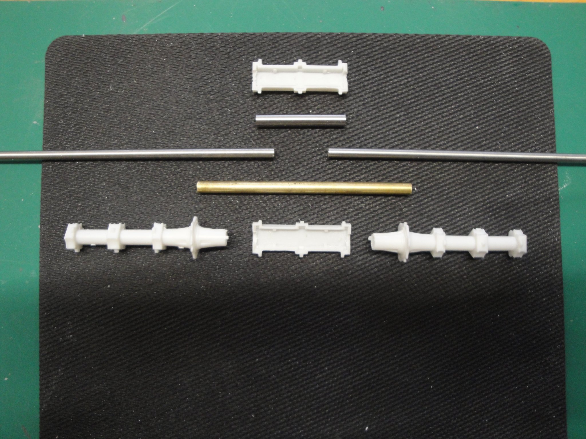
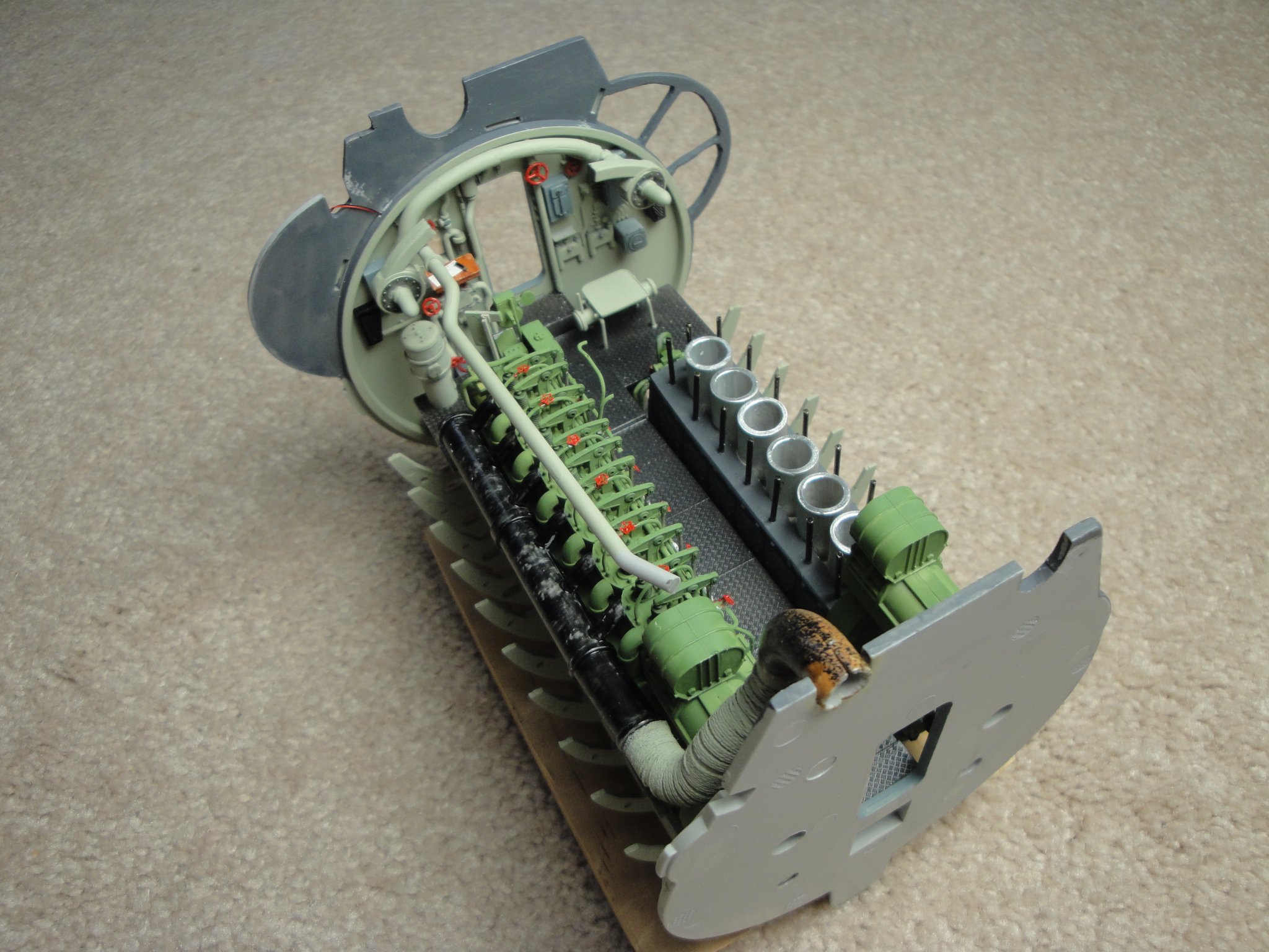
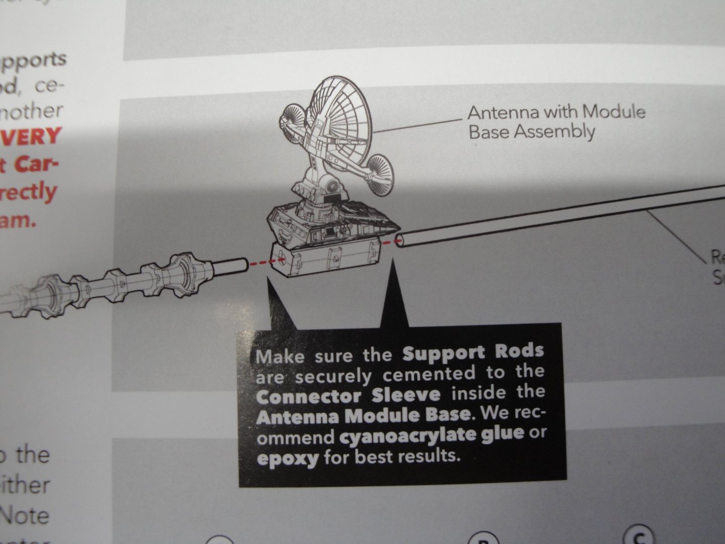
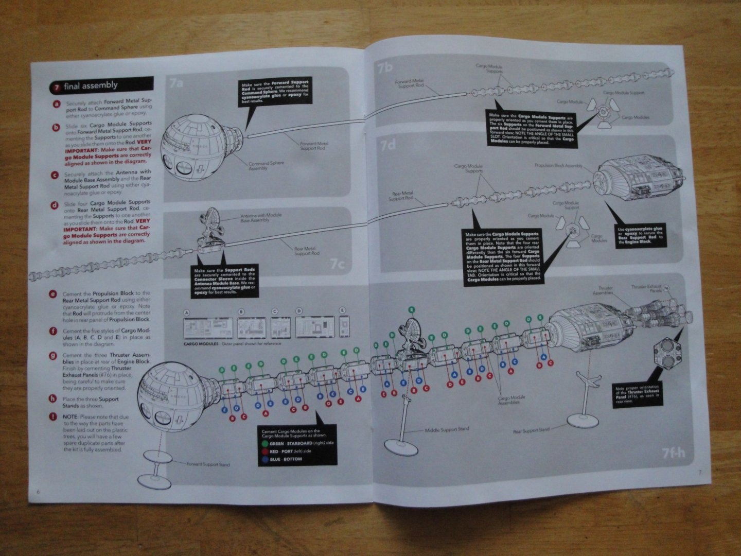
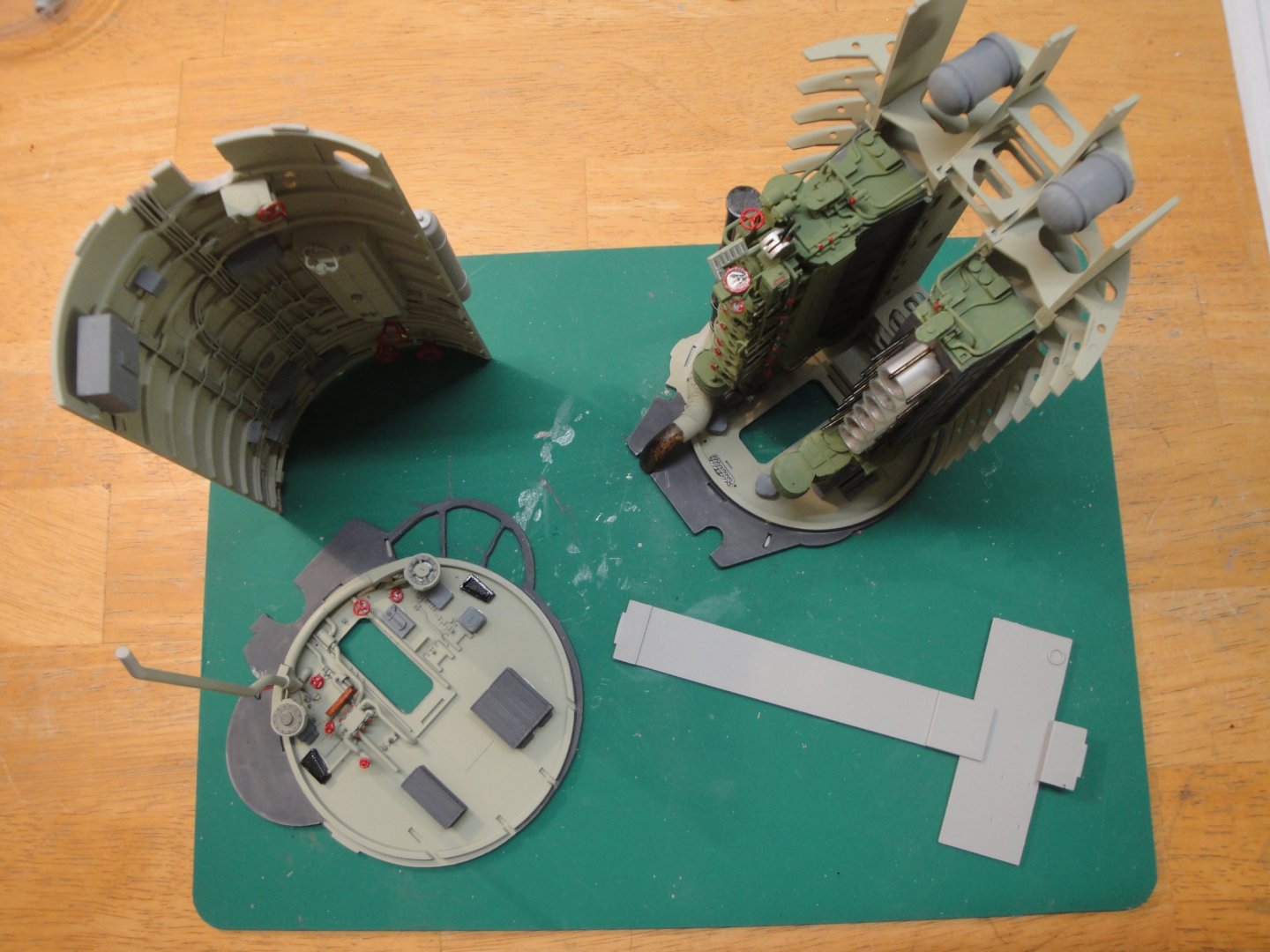
As I mentioned in the introduction of the Blog, I will be using the model as part of a celestial art piece. As such I will not be using the traditional way offered by Moebius, to display the kit. Moebius offers three stands under the living area (sphere), Earth antennae module and the propulsion block. The long model rests on these three rather flimsy stands to be displayed horizontally on a flat surface. My model is going to be "suspended" on the side and I wish to only have stands on the propulsion module and near the living quarters. In addition, I wish to provide some kind of illumination on the thrusters and on the main deck. Therefore, we have to rethink a little bit the kit and stiffen it considerably. In the Moebius kit, the two spines (realized by two metallic tubes of 4 mm) are connected inside the Earth antennae module: The piece of tube in charge of the coupling (as provided in the kit), is way too short and not tight enough. As a result, the two rods are sagging and not straight. It is okay if you go with the three stands approach of the kit. However, if you plan to have support only on both ends of the vessel, the spine will sag and look more like an arch. So, we need to stiffen it up. The following picture shows what I have in mind: The top piece of tube is what Moebius provides in the kit. Then we have the two rods of 4 mm each. The brass tube I decided to use offers an additional inch of support on both sides and fits very tightly on the 4 mm rods. When lining up everything, the spine is straight and sturdy. The brass tube is #129 3/16 x 0.014 made by K&S Engineering and can be found in almost all Hobby Shops. The two adjacent modules have to be gently enlarged to accommodate the extra diameter of the brass tube. This is done first with a bit of 4.5 mm and then fine-tuned with a round file (I do not have a 4.8 mm bit which would have been perfect. The coupling is very tight and will hopefully provide us with a "straight" vessel. Yves

-
Folks, I have narrowed my decision to the following build, for the time being: Thank you all for the many "likes" and wonderful support, all along the building of that massive and complex submarine. Yves
-
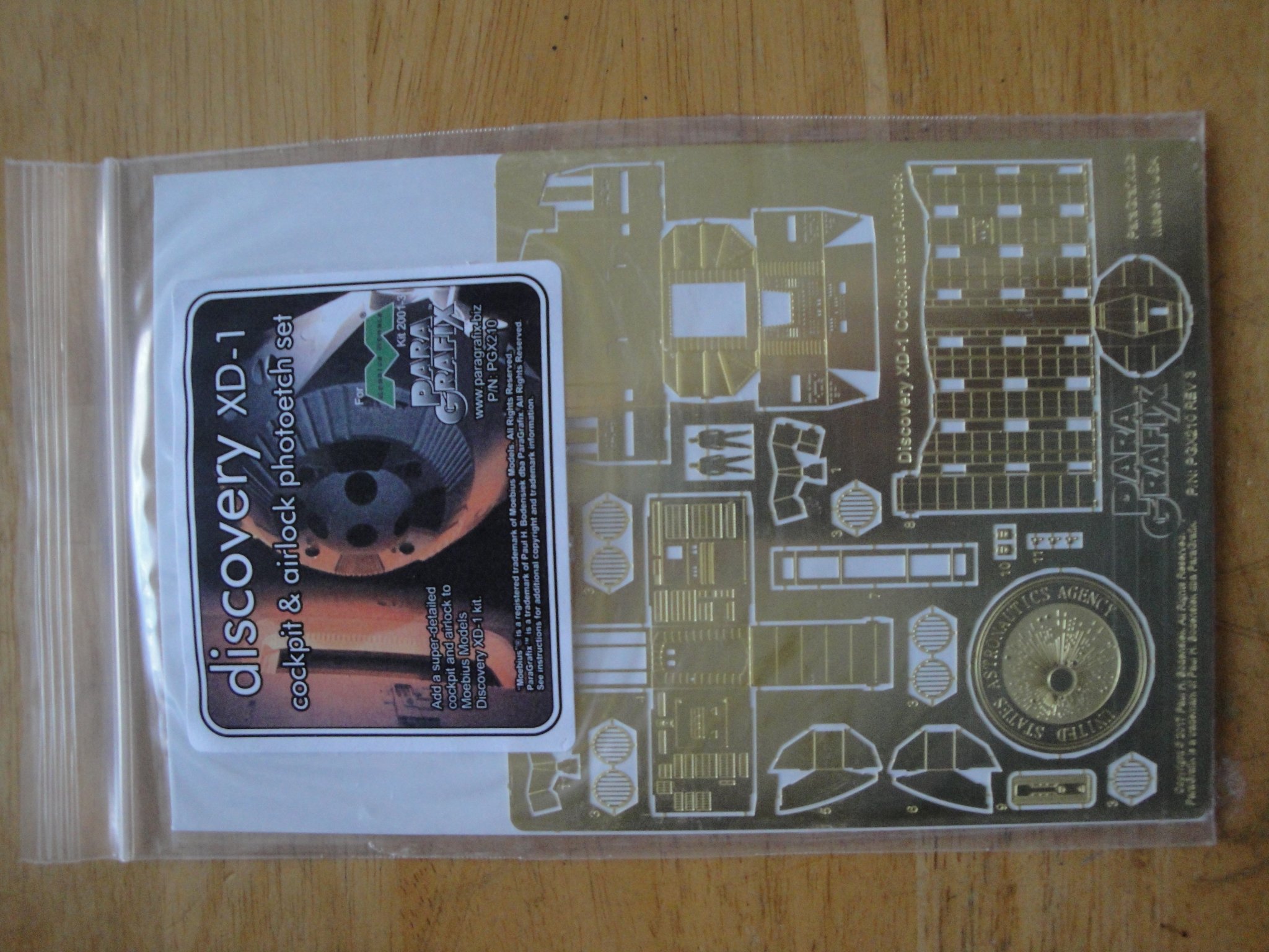
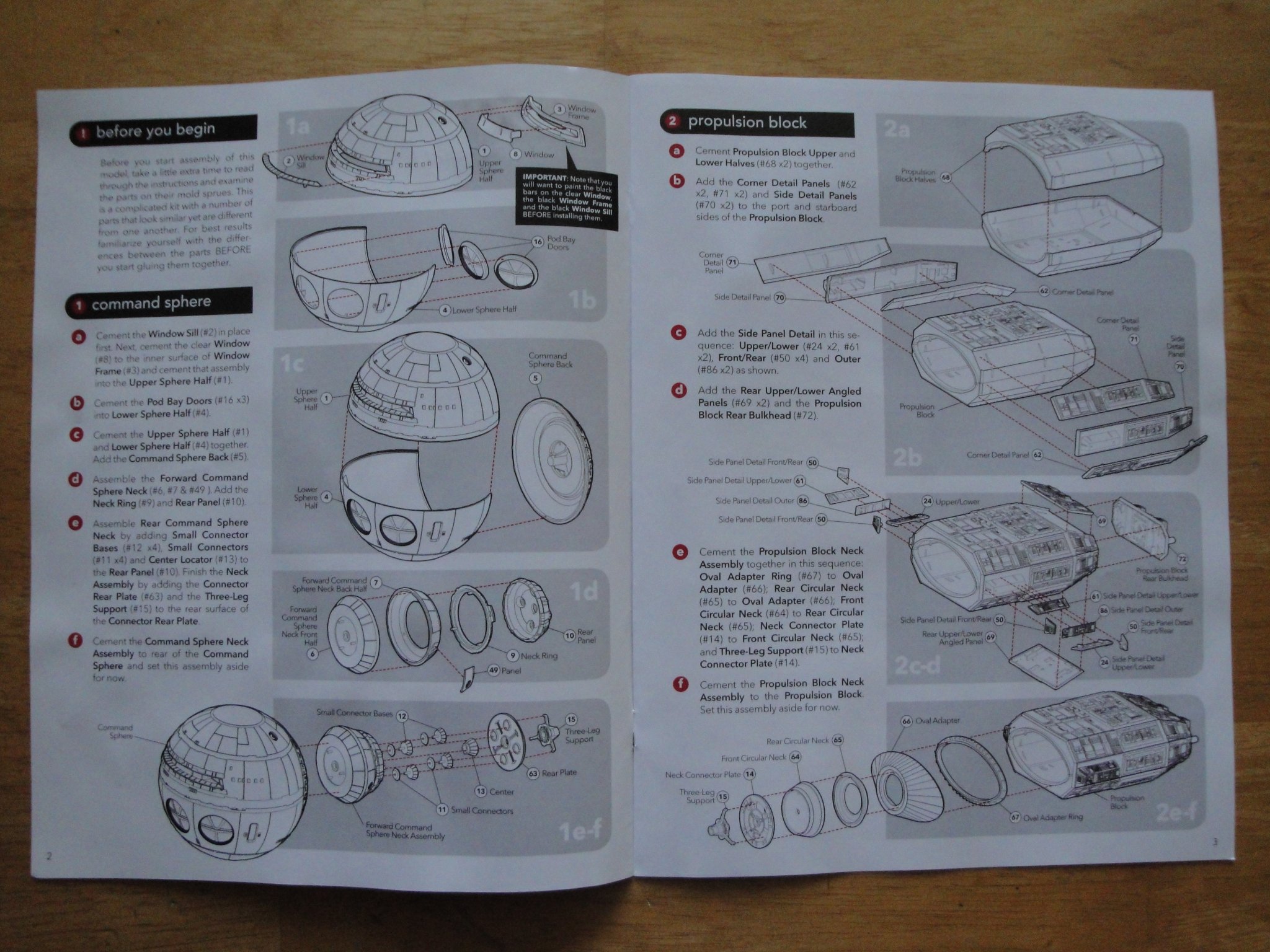
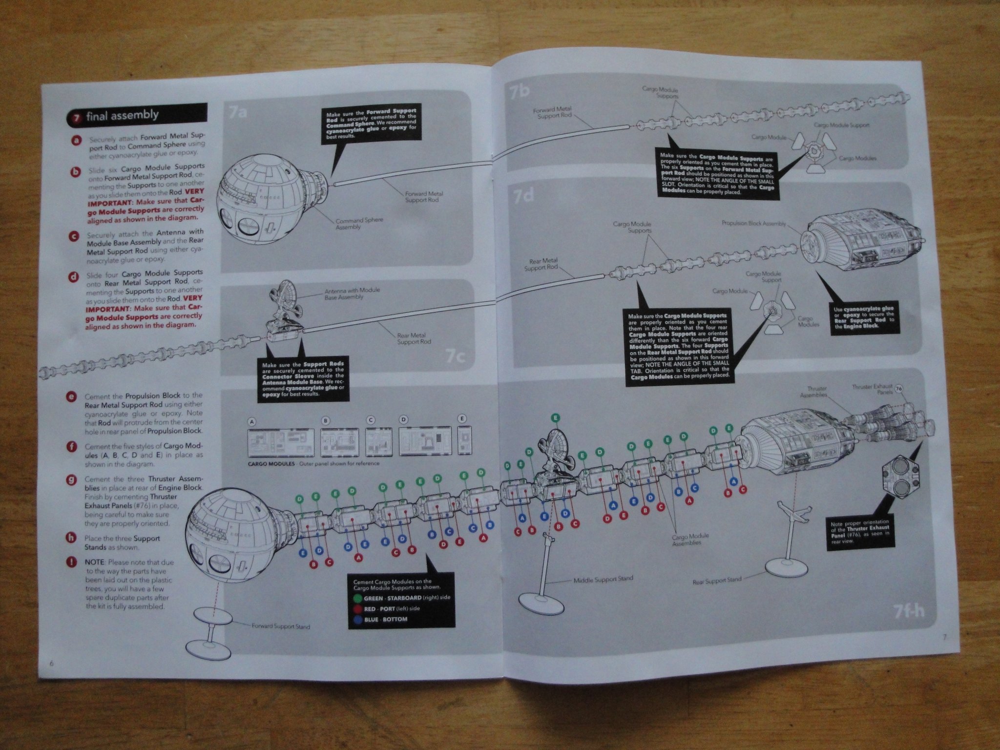
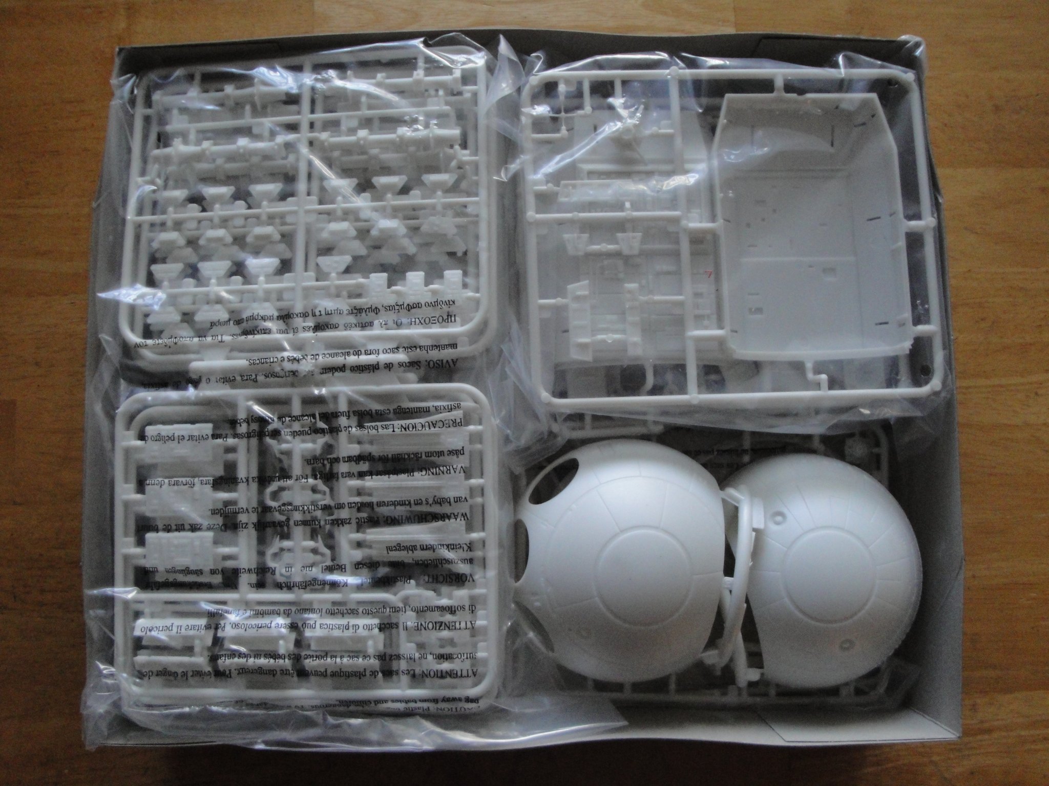
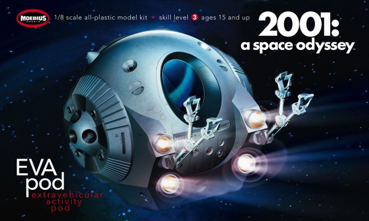
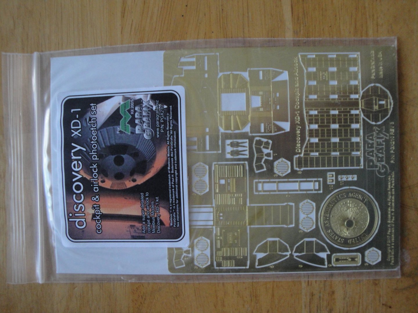
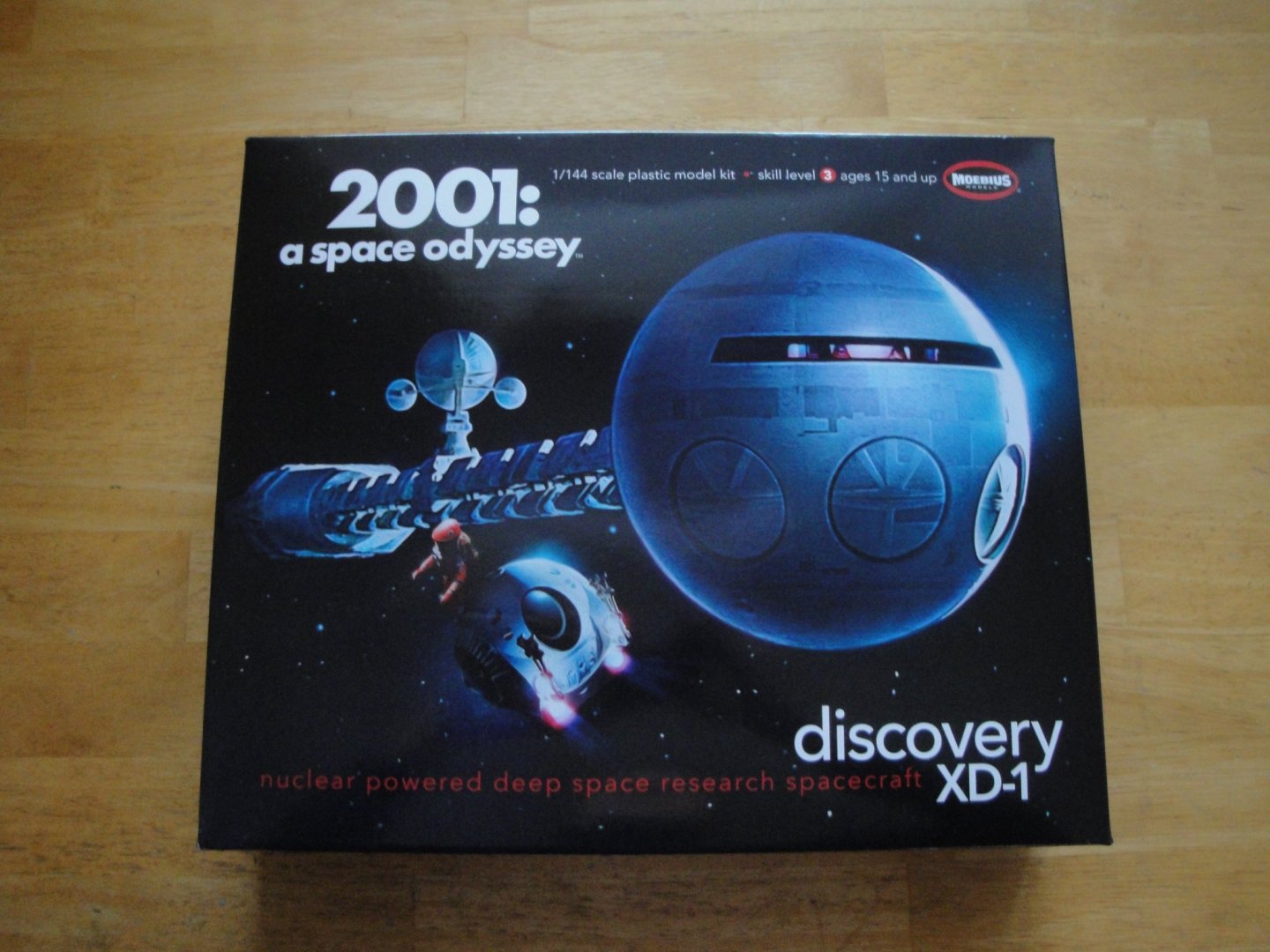
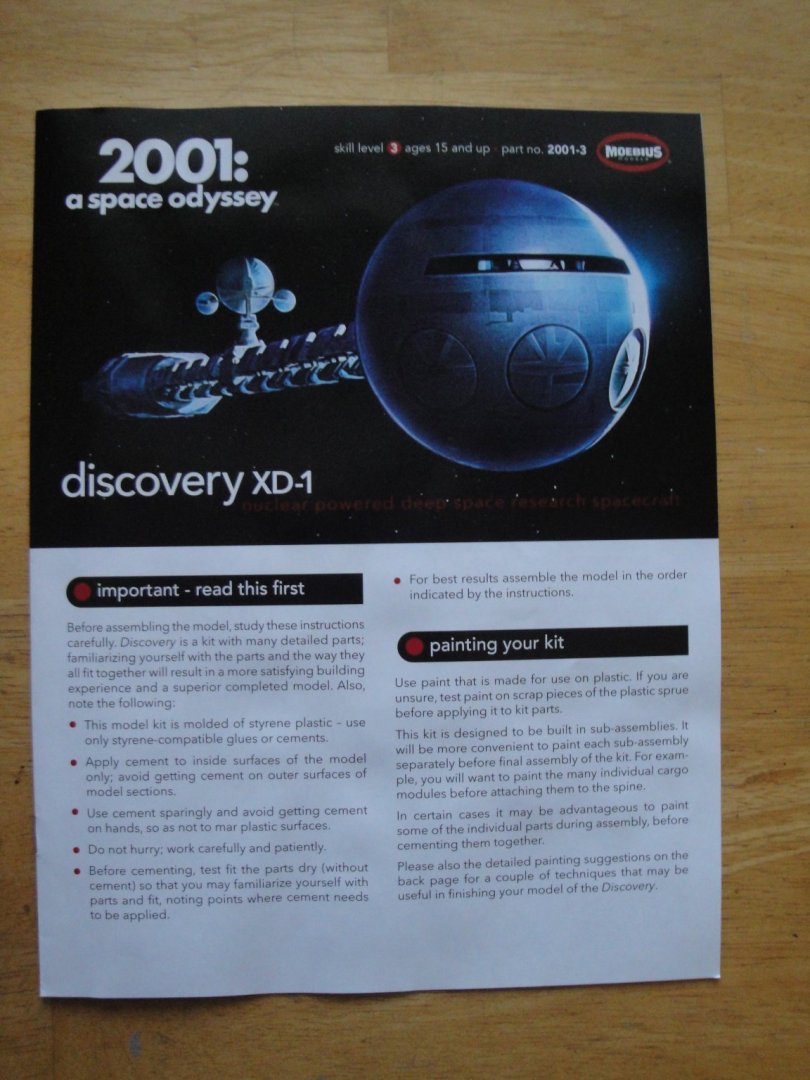
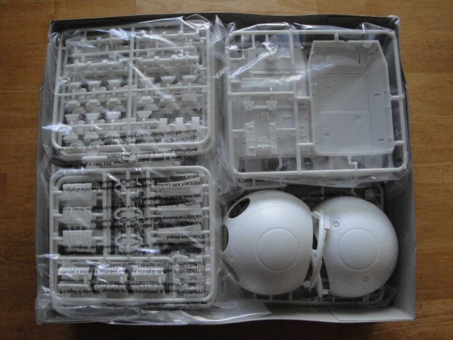
Folks, This is the beginning of another project I have been trying to realize for a while. I recently got the kit from Free-Time Hobbies in Georgia, as they were having a very interesting sale. Like many of you, I watched the 2001 A Space Odyssey movie, in 1969 when it came out, fresh from the genius of Stanley Kubrick. I was just 10 years old and that movie created a life lasting impression on me. For many years, only resin kits of the various space crafts were available. Then Moebius decided to create a series of 1/144 based kits to satisfy the 2001 enthusiasts. XD-1 Discovery is the latest kit produced in 1/144 scale, not counting the enormous EVA 1/8 Pod kit that was recently released: The enormous Deep Space Exploration vessel driven by a psychotic HAL 9000 en route to the vicinity of Jupiter, has always attracted me and when the opportunity to build that magnificent model presented itself, I jumped on it. There are multiple videos and Blogs on the Internet of very talented modelers who have completed this beautiful model. I am not planning to even come closer to their talents. Instead, I will use the model in a different way to produce a piece of art made of mixed-medias as they call it in the artistic realms. I will provide more details when we get to that stage. In the meantime, let's take a look at the kit: The box is very dense and literally crammed with parts: Lots of the parts are the same as we have to build multiple bays arranged along the spine of the vessel. The instructions booklet is simple but carefully written and clearly organized: On the Photo-Etched side, a few additional kits are available: one for the PODs bay and one for the main control deck. Not planning to represent the POD bay opened, I only purchased the Main Deck set from Para Grafix. Notice that even though the focus of the set is on the living area, it also provides the thrusters grills on the Propulsion Block Yves


- 119 replies
-
- 15
-

-
What a terrific collection. You Sir, love planes. Yves
-
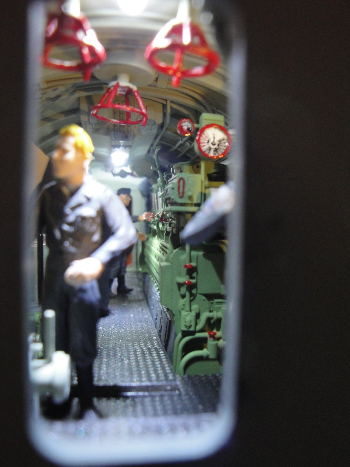
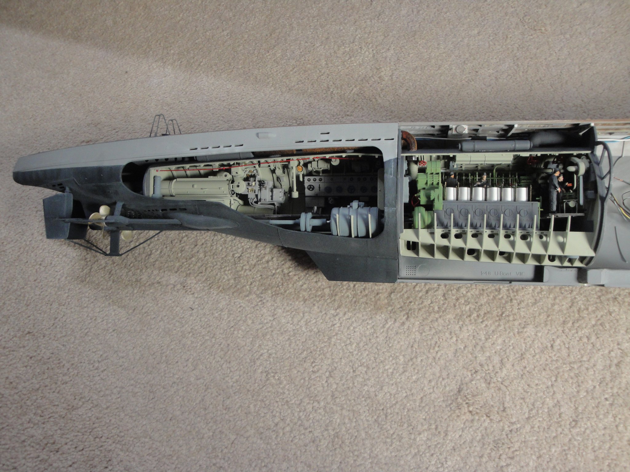
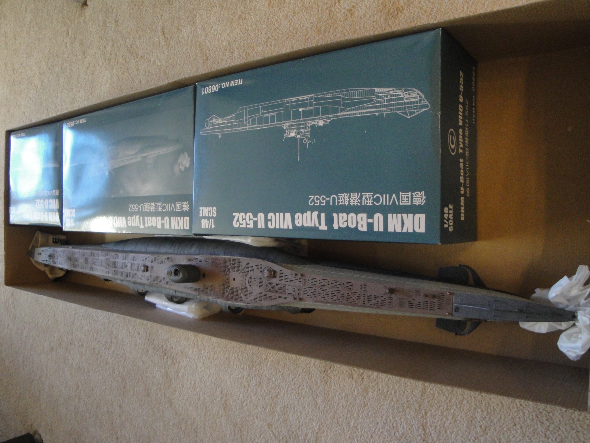
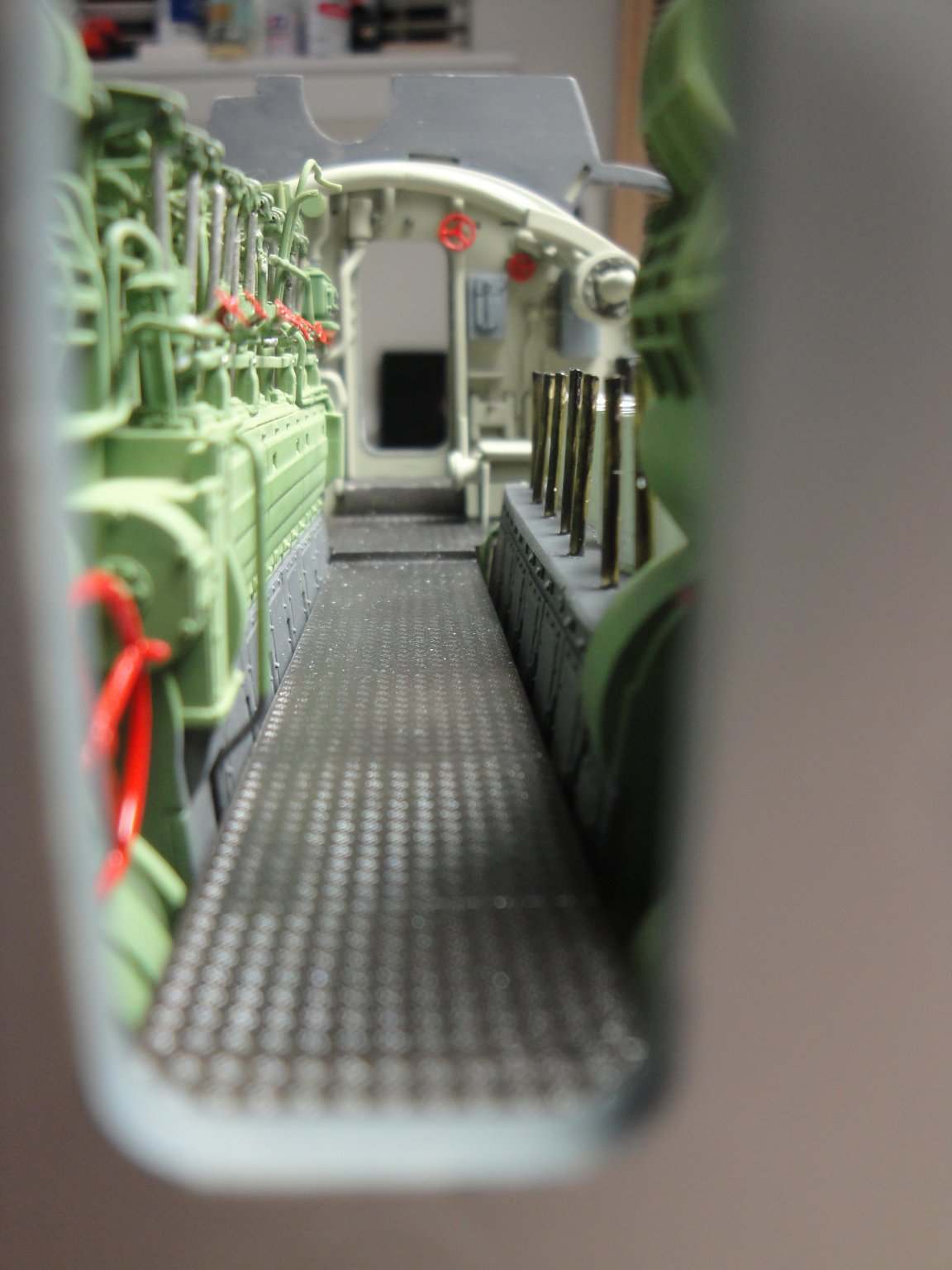
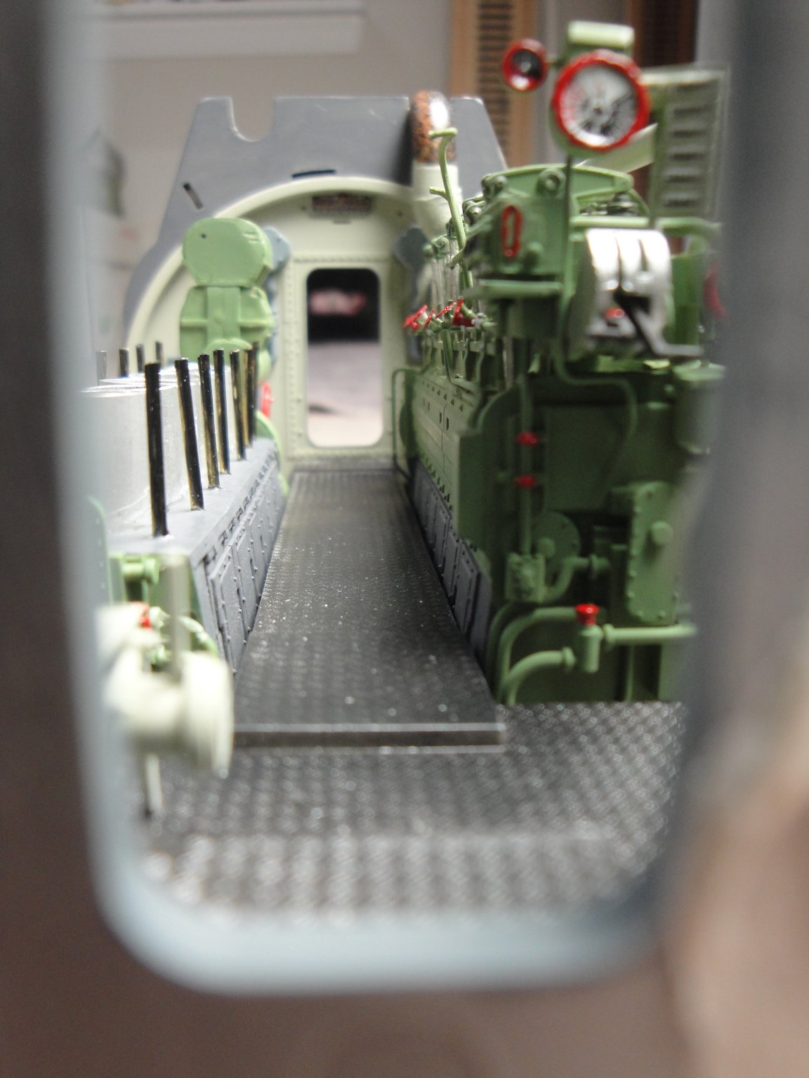
Merry Christmas to all and my Best wishes of Health, Love, Friendship and modeling passion for the New Year. A few updates on that Christmas day. The Diesel engine compartment is now completed and the pressure hull has been installed. The two pieces of pipes for the exhaust as well as the fresh air ingress pipe have been glued and sanded flush with the bulkheads. I have added an extra air tank on the pressure hull, tanks that were used to crank up the diesel engines. The electrical wiring has been completed and verified. We have four white LEDs in series, requiring close to 11 Volts to illuminate. With an adjustable resistor, I will be able to harmonize the intensity of the light, with the other compartments. The current is about 3 mA. The LED above the wood desk is a micro-LED and provides a more classic and yellowish color than the ceiling lights. It is now time to insert the module into the hull. Again, at this point, it is difficult and delicate to go back. The existing wires are carefully inserted in the slots provided by Trumpeter, on each bulkhead. The module inserts in the rear compartment, through the torpedo recess and two large pins, hidden by some apparatus. The module is only glued on the front bulkhead. Closing the starboard hull, this is what we will be able to see: You see the importance of creating the side tanks openings: And a couple of pictures for the claustrophobic's: Folks, I have reached a point where I have two modules to build and countless details to finish on the deck, conning tower, guns and on top of each module, when visible. Some electrical work needs to be completed, as well as some paint touch-ups and light weathering in multiple places. I will finish this model but have decided to take a little break from it and tackle instead one of the two projects I have at heart. One of them (there are many...) could go in this forum as it is boat related. The other one, not being something that floats on water would have to be developed in the "Shore Leave" section. Whatever is being done, I will provide a link to keep you updated. The Type VIIc will be placed back in its box (yes, the fully assembled hull fits) and stored for a few weeks or months. I wish you all Happy and Relaxing Holidays, and passion, fire and energy for many projects. Yves


- 760 replies
-
- 19
-
-
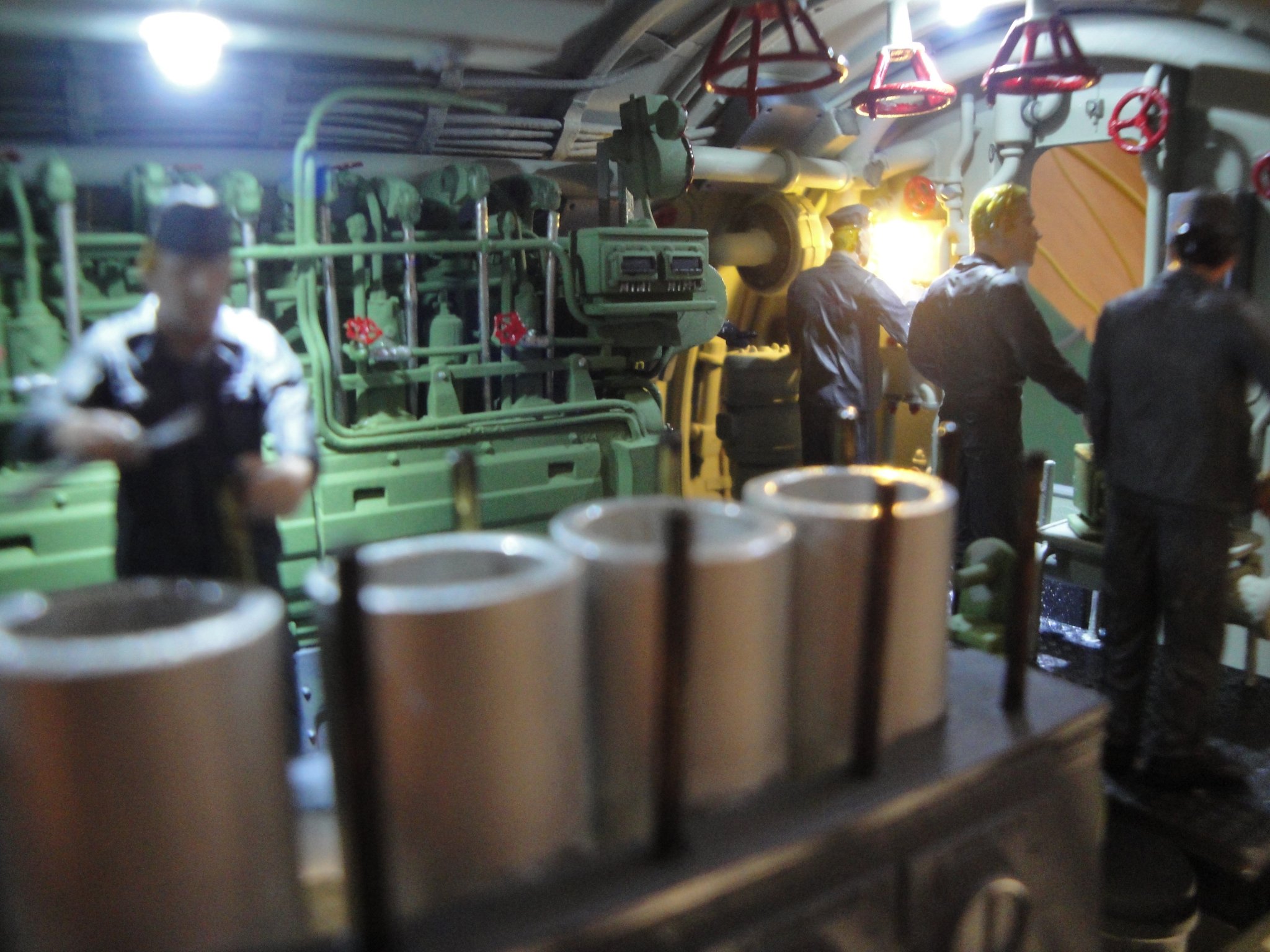
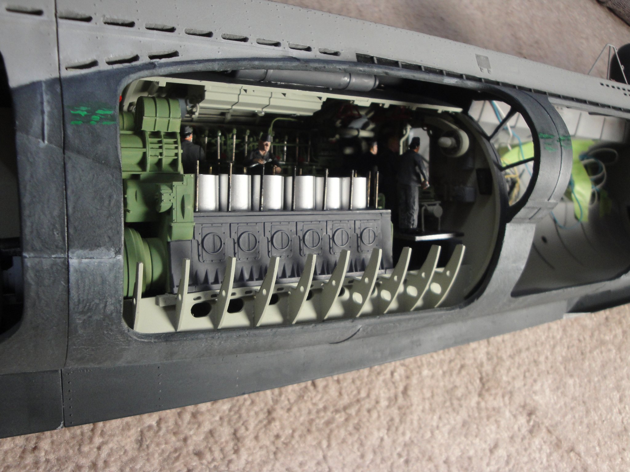
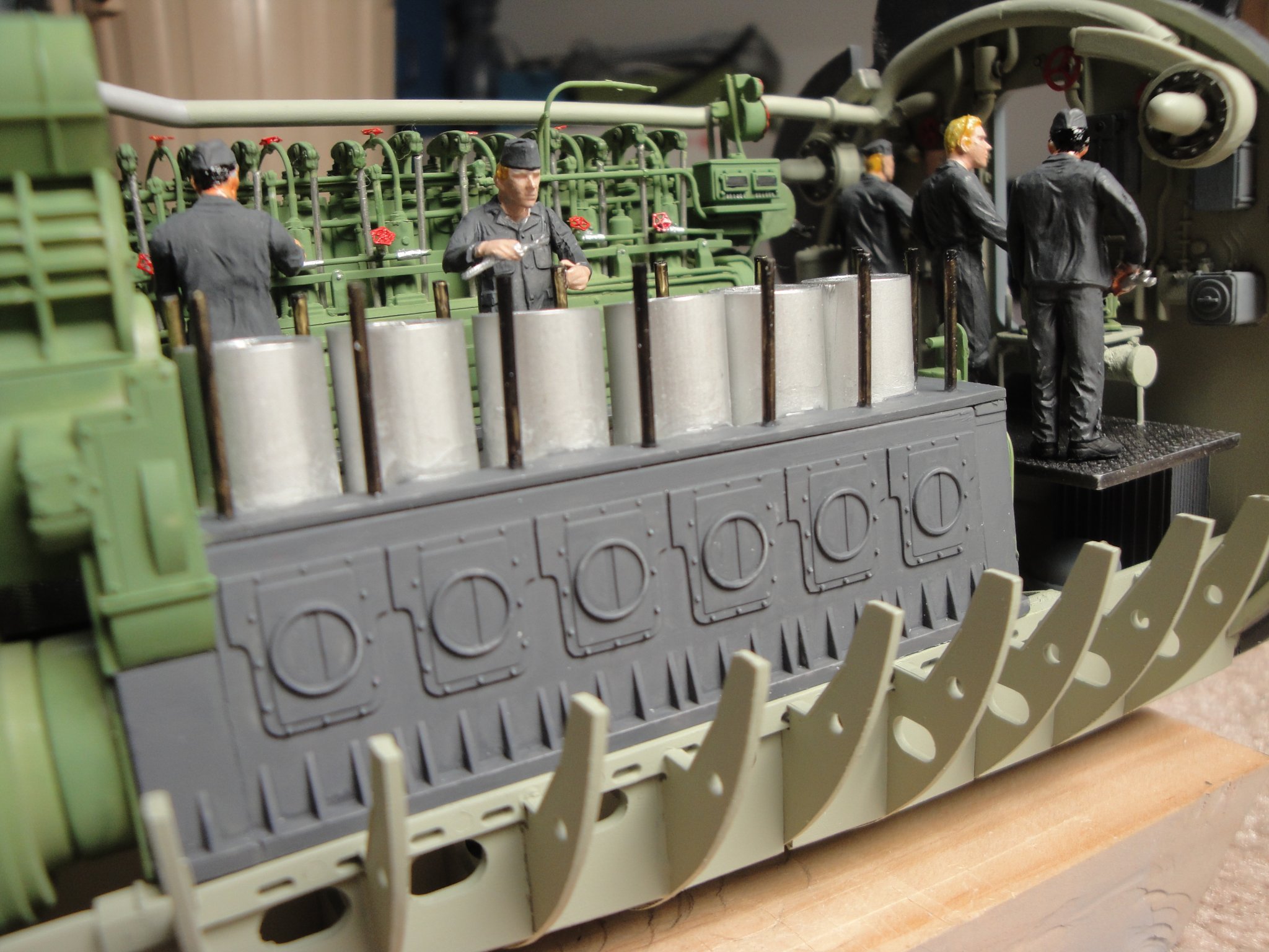
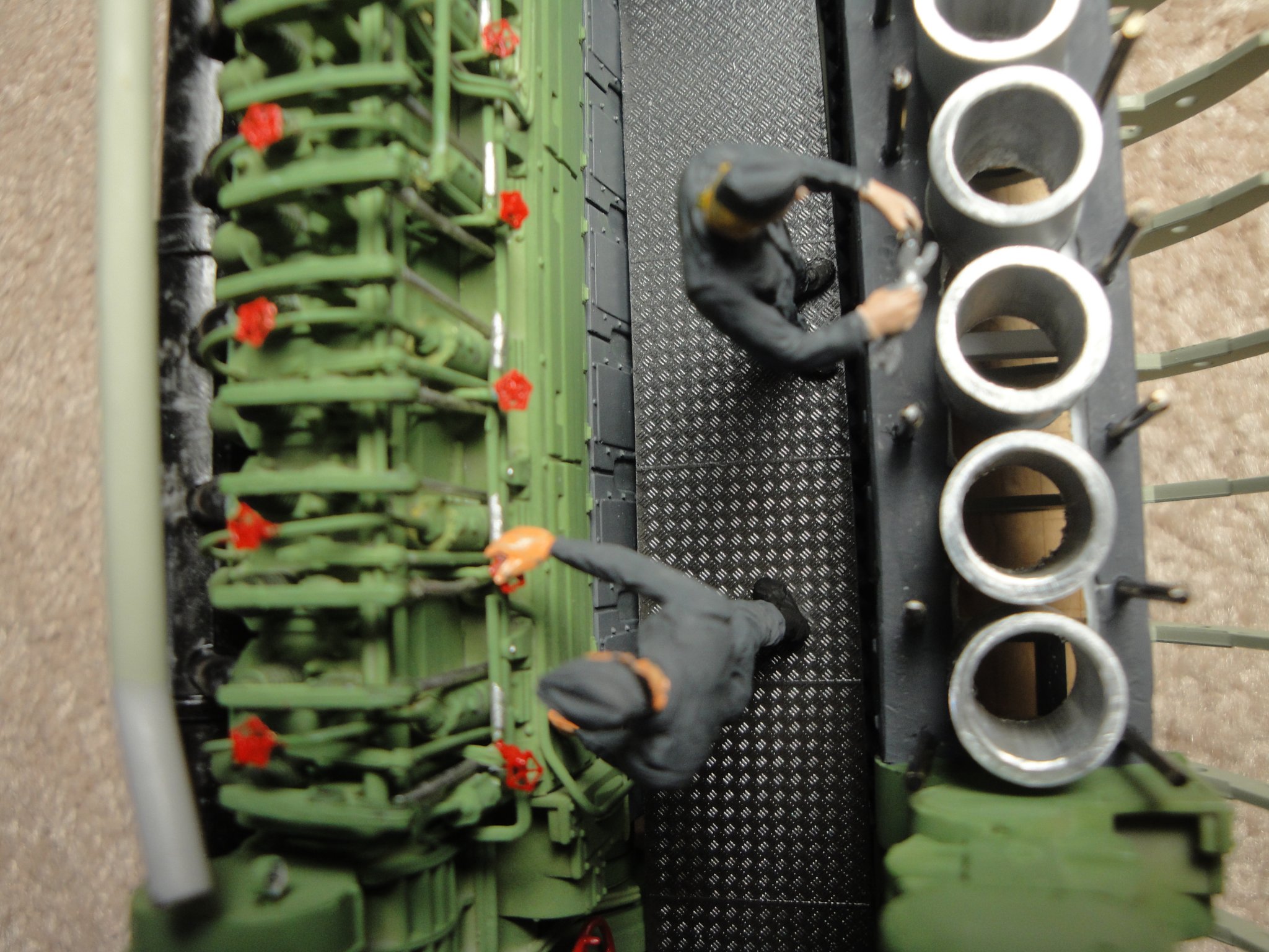
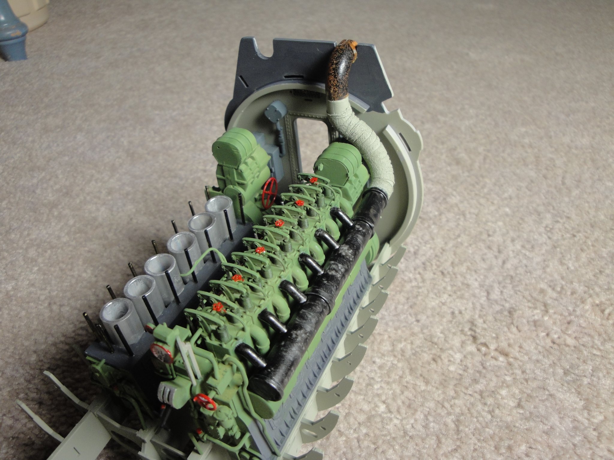
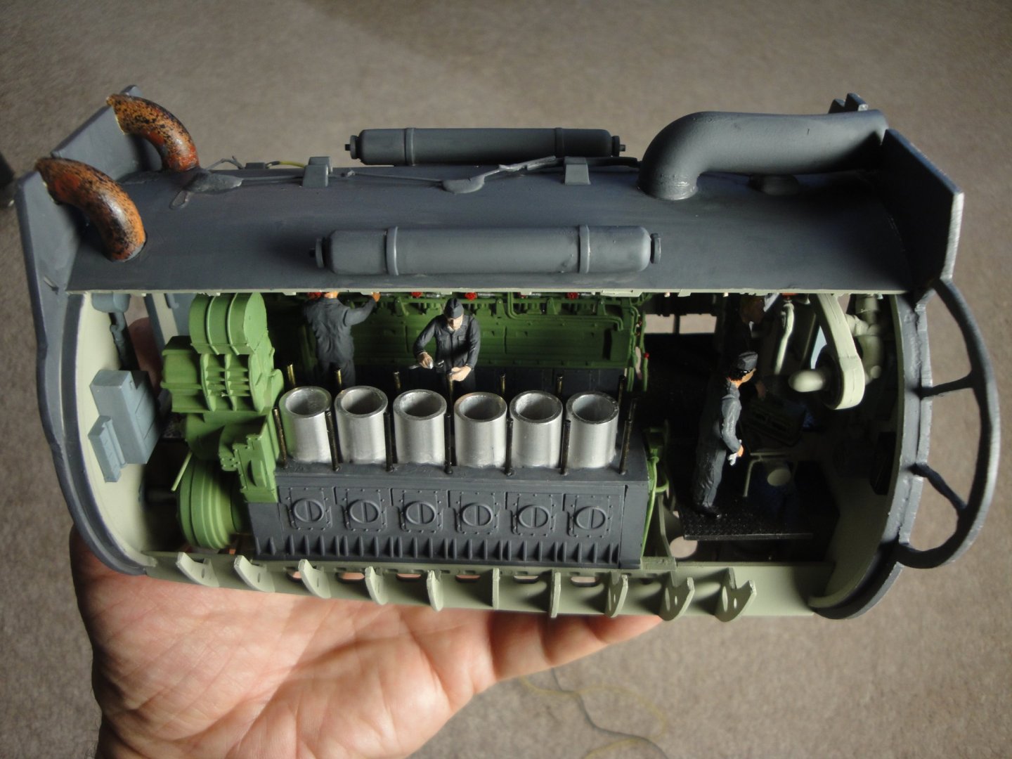
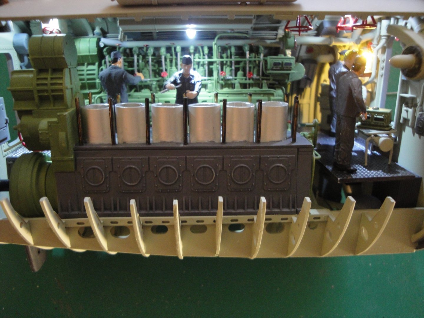
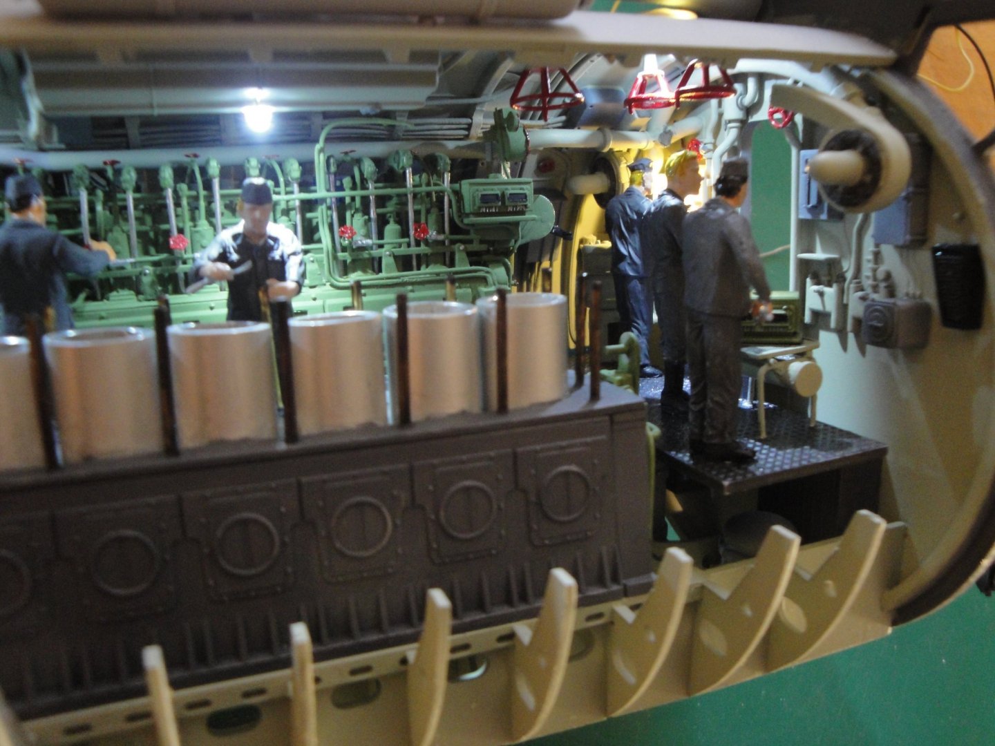
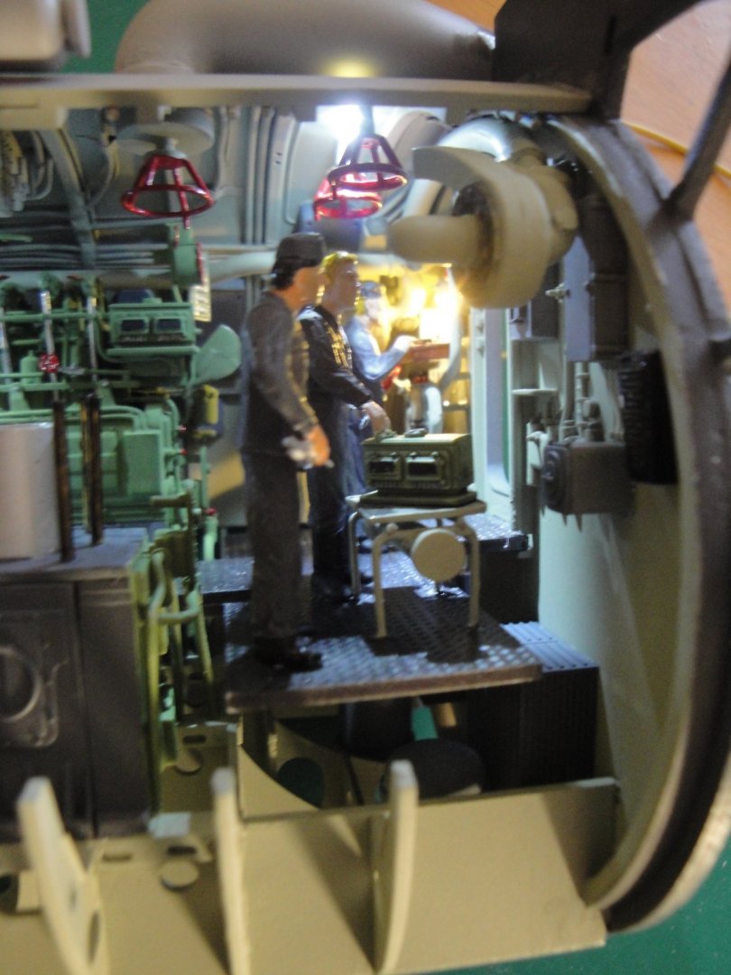
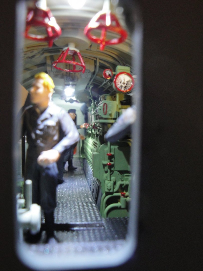
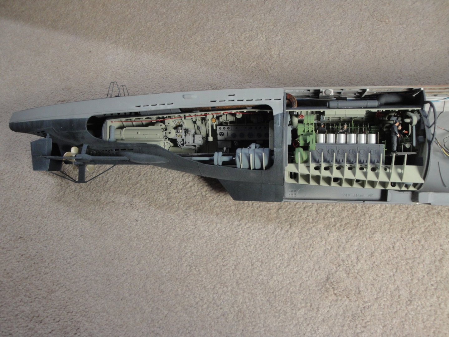
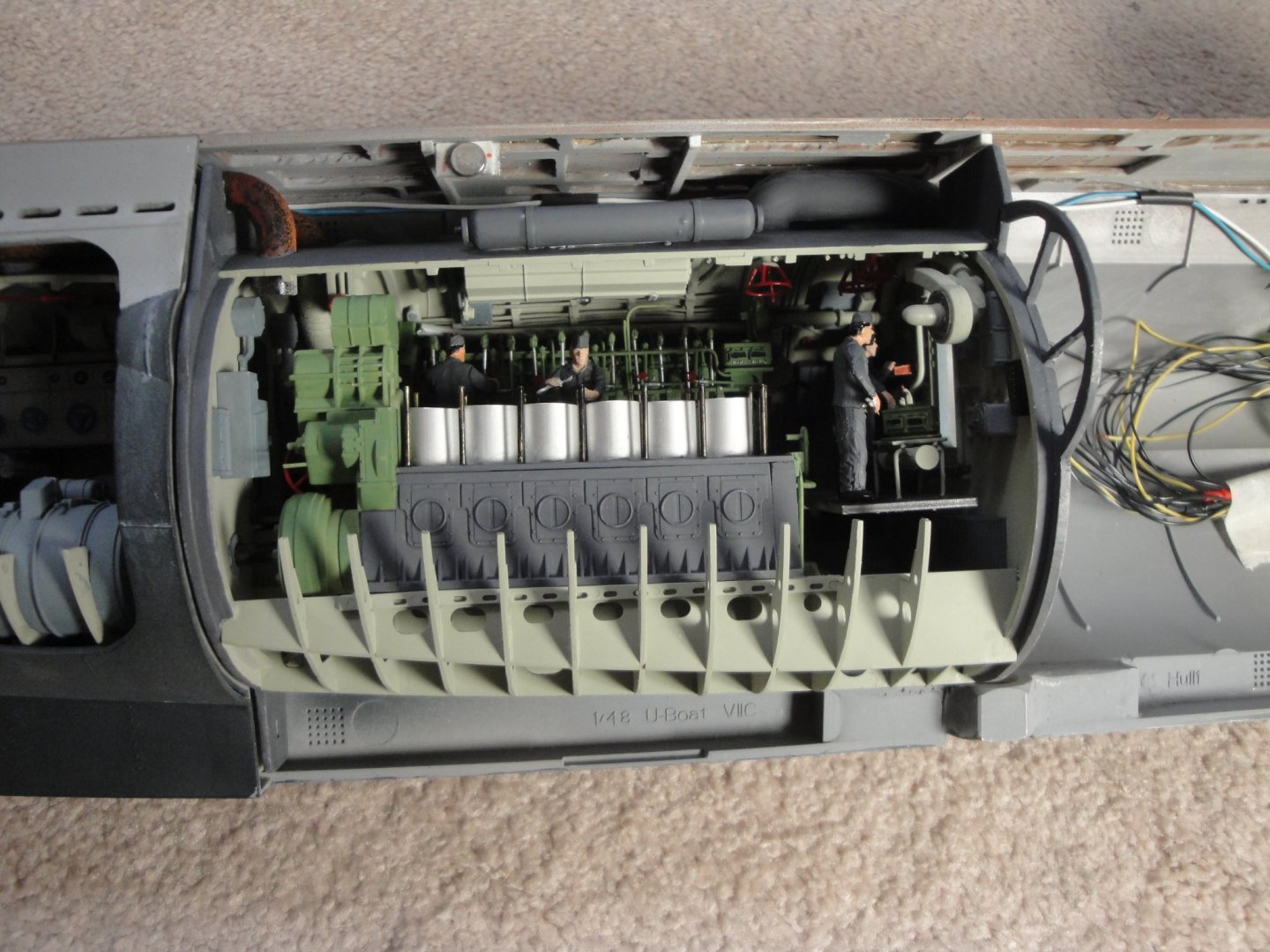
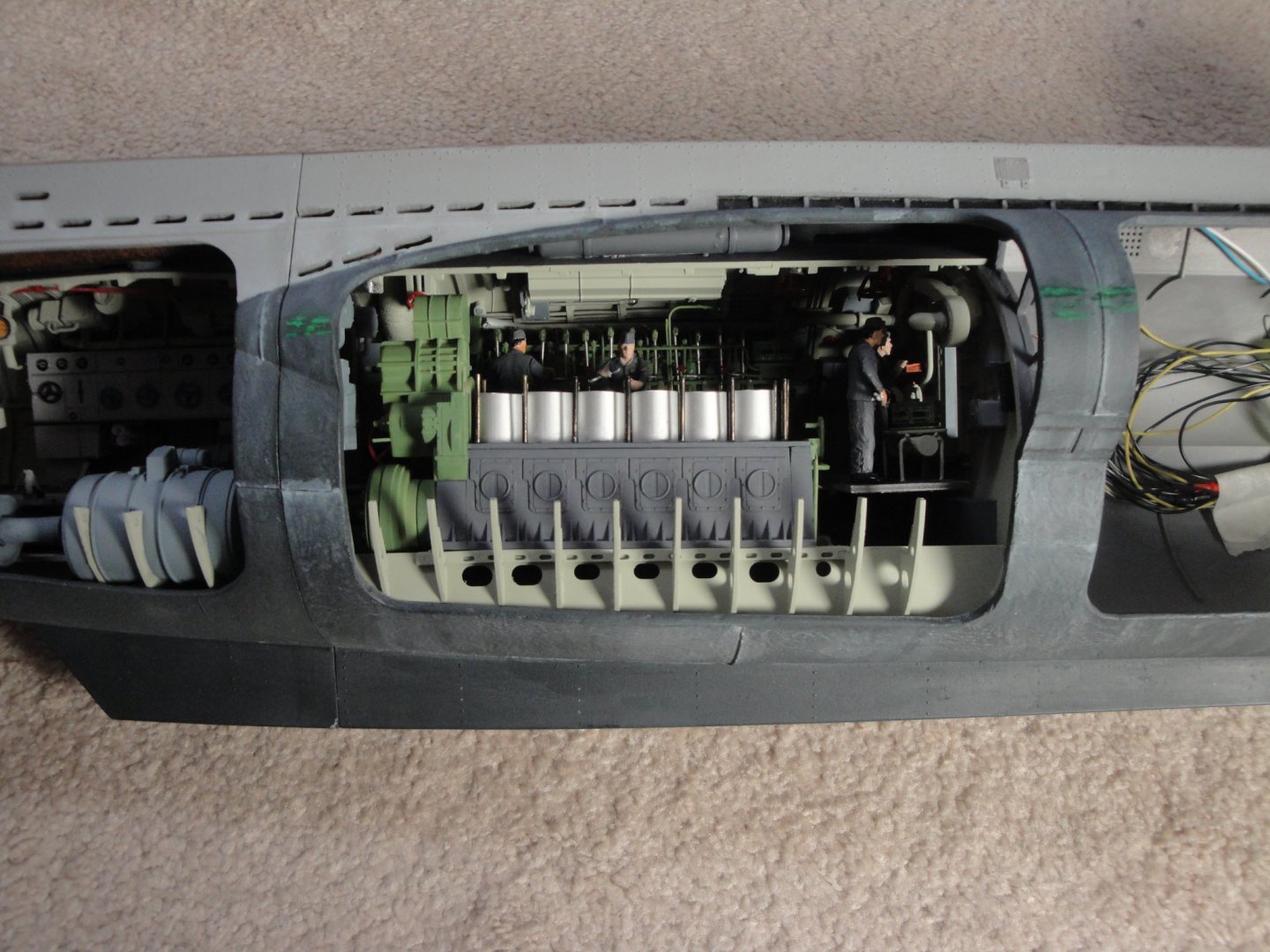
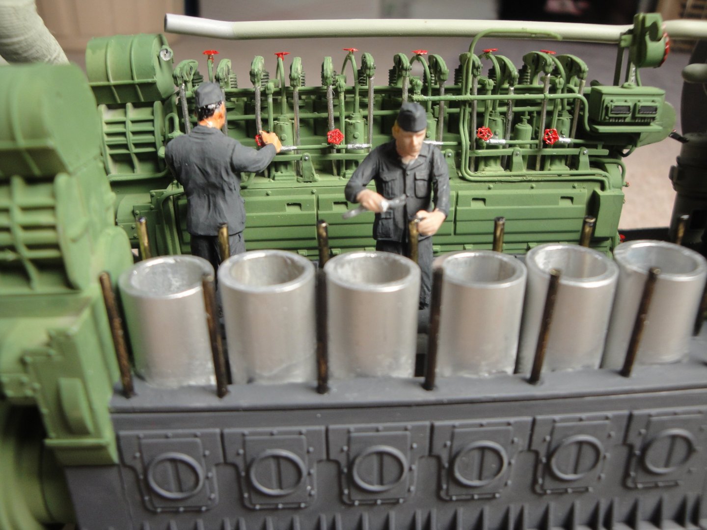
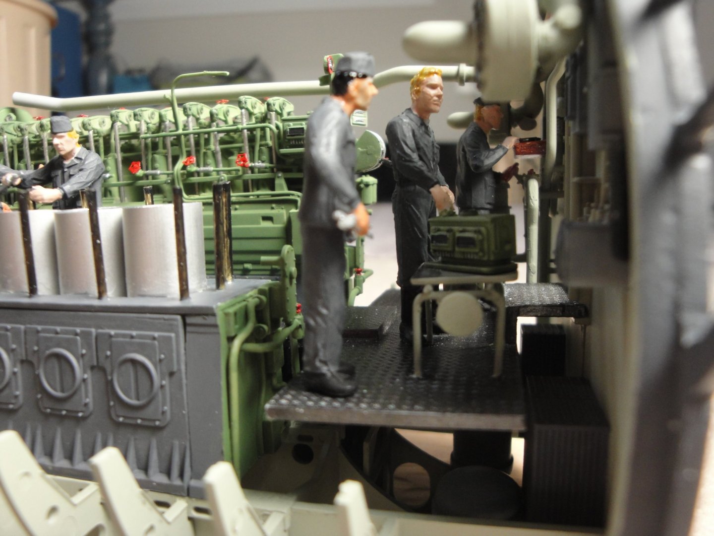
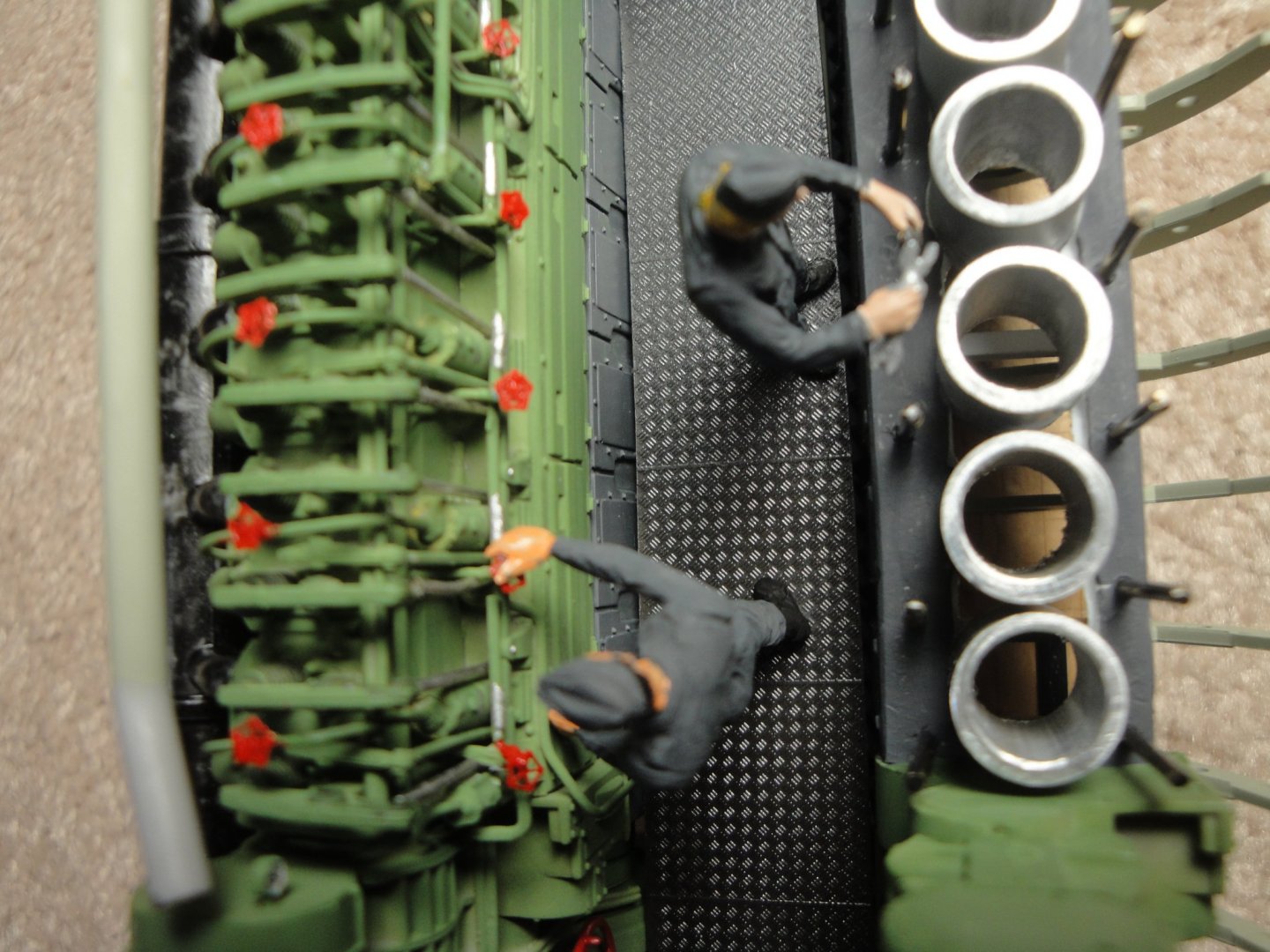
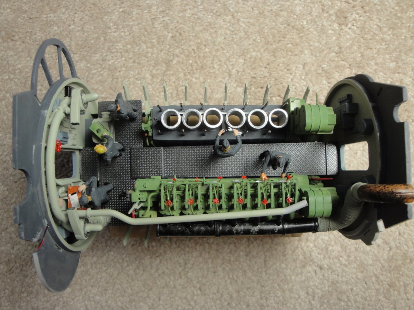
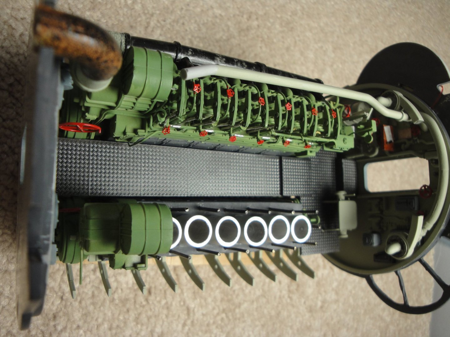
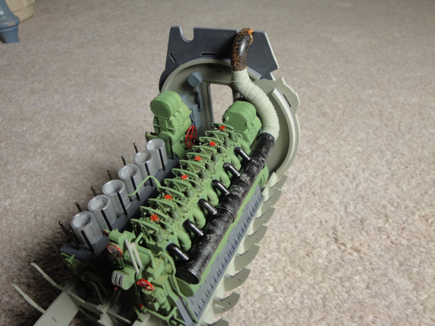
I suspect that this kind of maintenance could not have been done at sea. This is just a way to show how the engine was made, the sheer size of the cylinders and to allow the observer to see the complete engine in the background. It is a model and not a representation of how it was used during a sea patrol. Many thanks for all the "likes" and support. It is very motivating. Yves
-
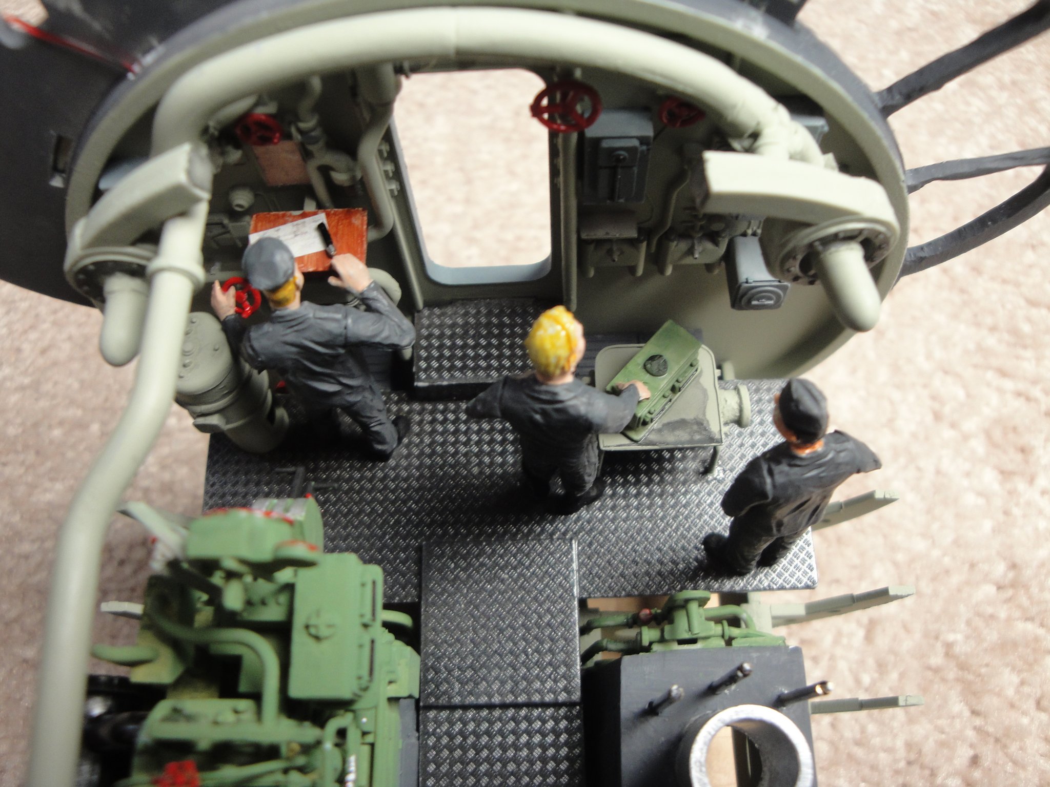
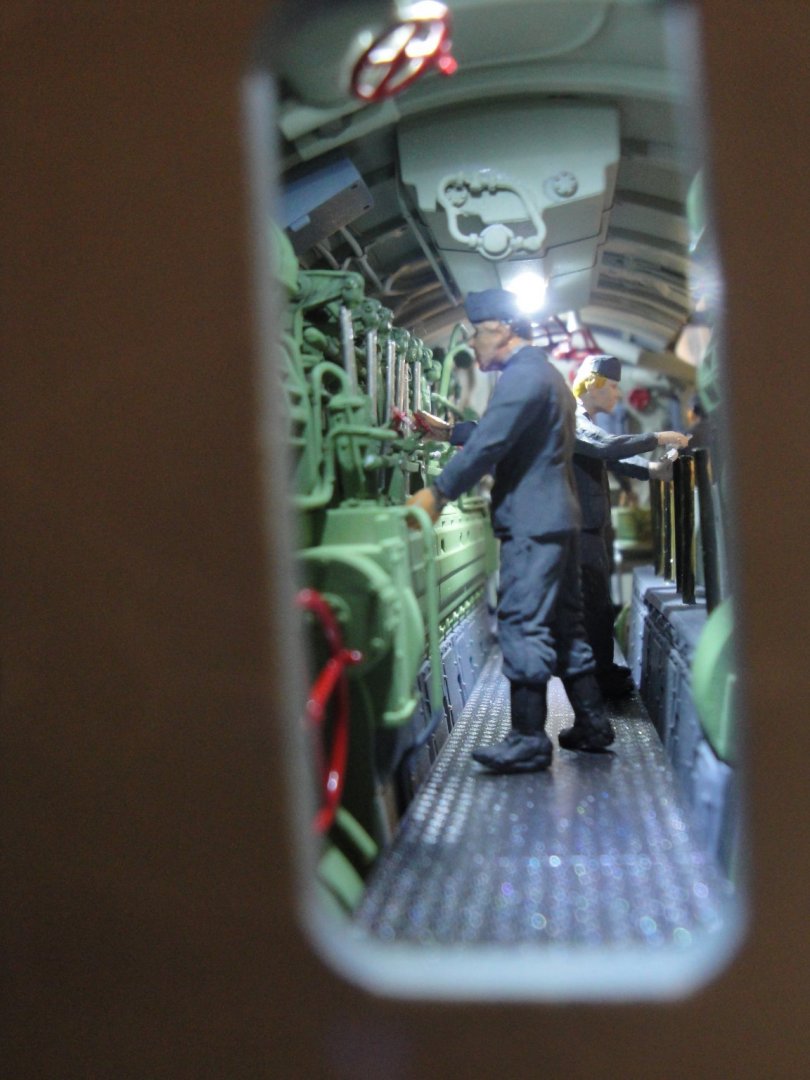
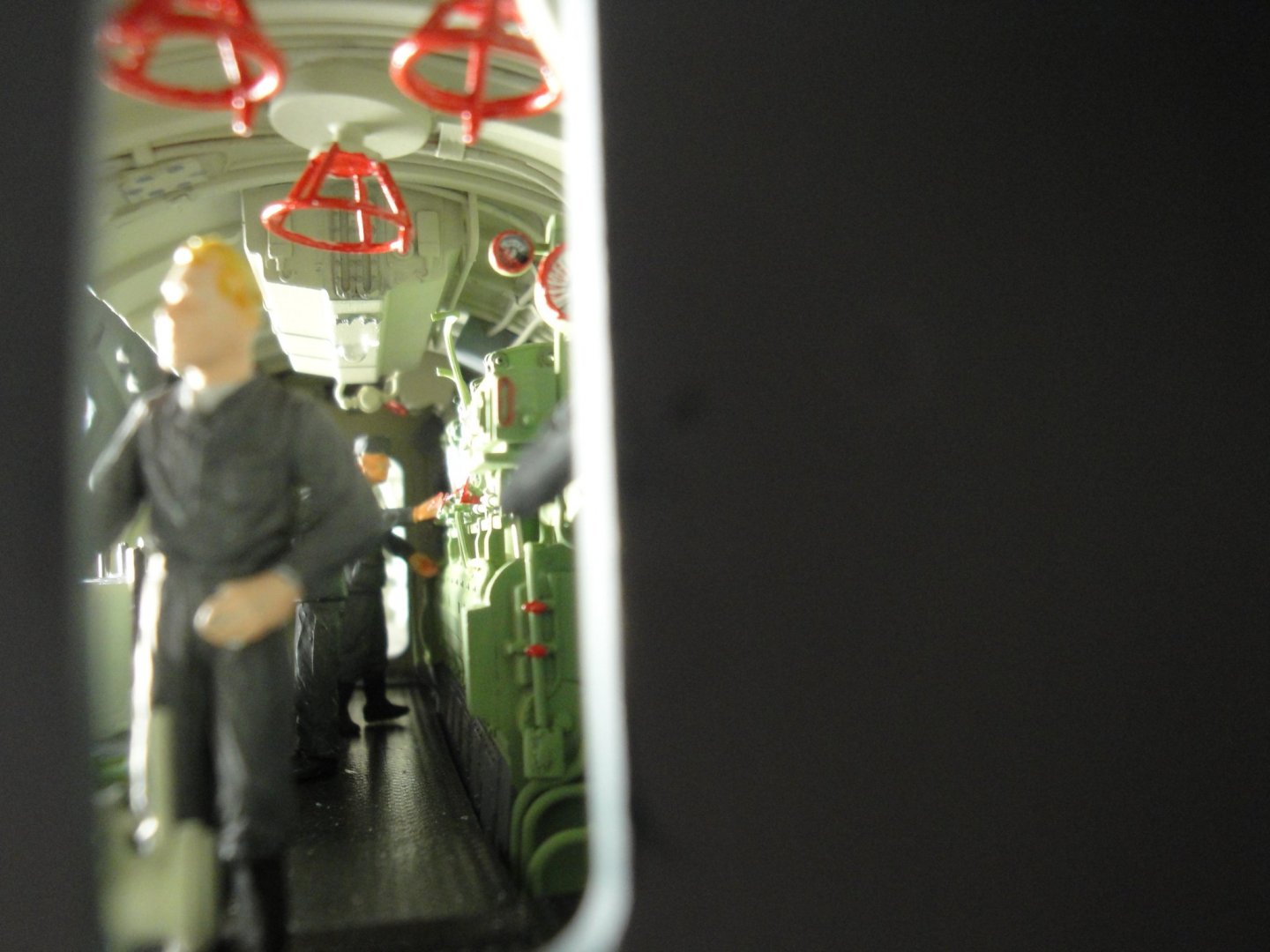
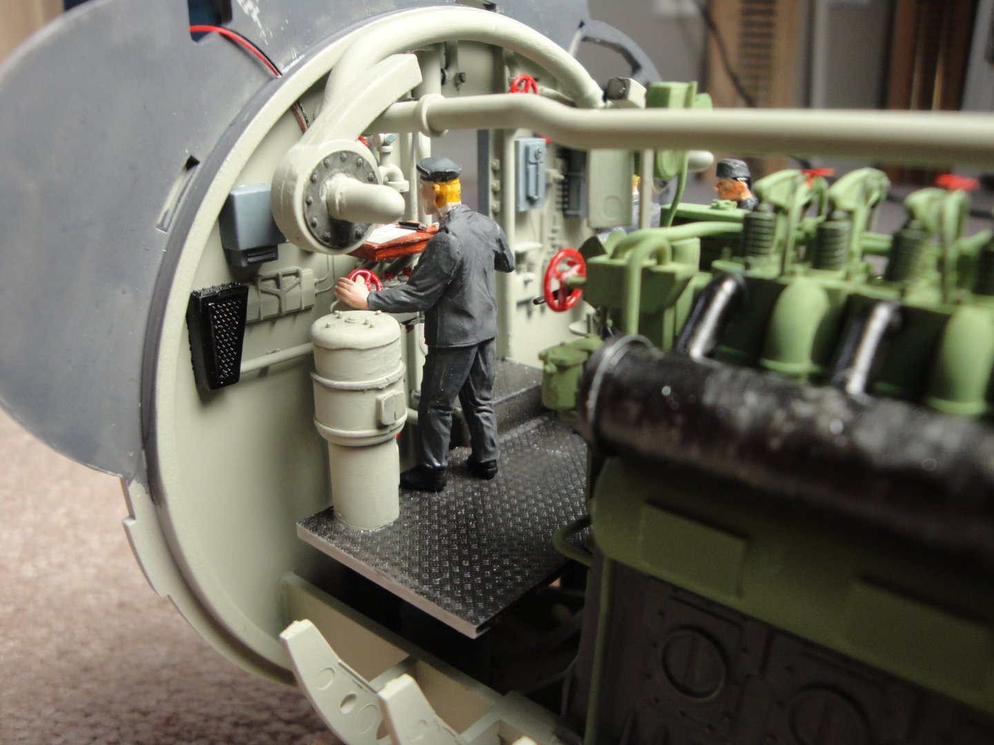
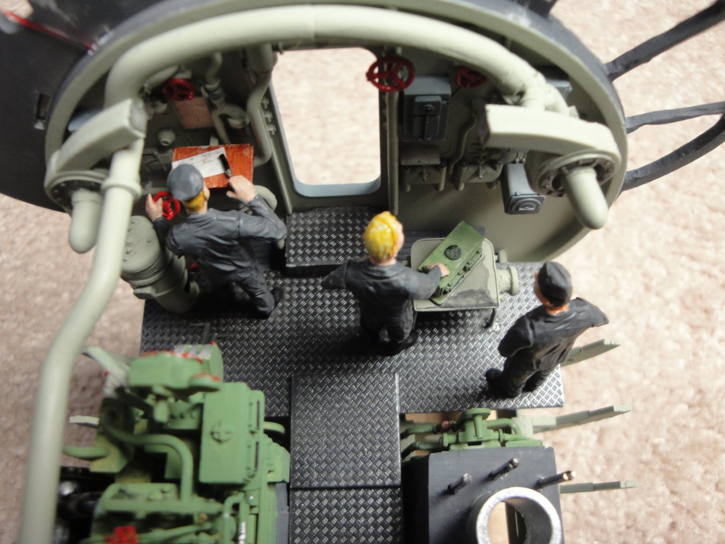
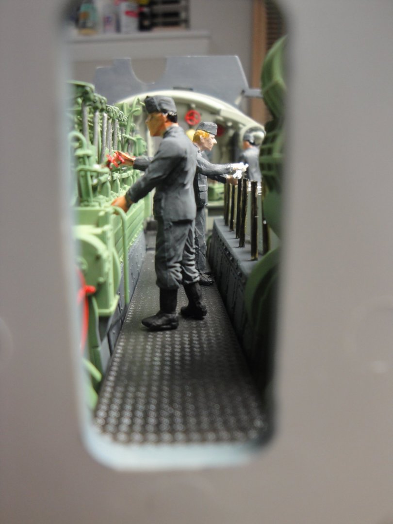
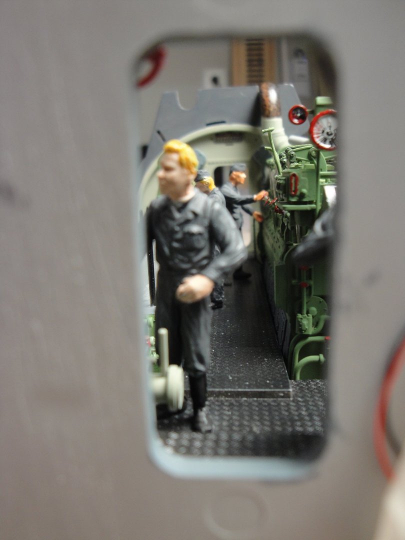
The crew is in place, around the diesel engines. It is the last piece of details on this compartment, before sealing it with the pressure hull. A few pictures.... Everybody is very busy.... Let's enjoy all these perspectives, because it will not be possible again, when the pressure hull is glued on top. Yves

- 760 replies
-
- 26
-
-
You may not be good with computer, but you build superb models. Yves
-
Beautiful Model Denis. I love these barnacles stuck to the piles.... Are you going to model some water and light waves, too? Yves
-
Don, I have read some publications from Maciek. Thanks for all the good info you are providing to this thread and for your fantastic book. Yves
-
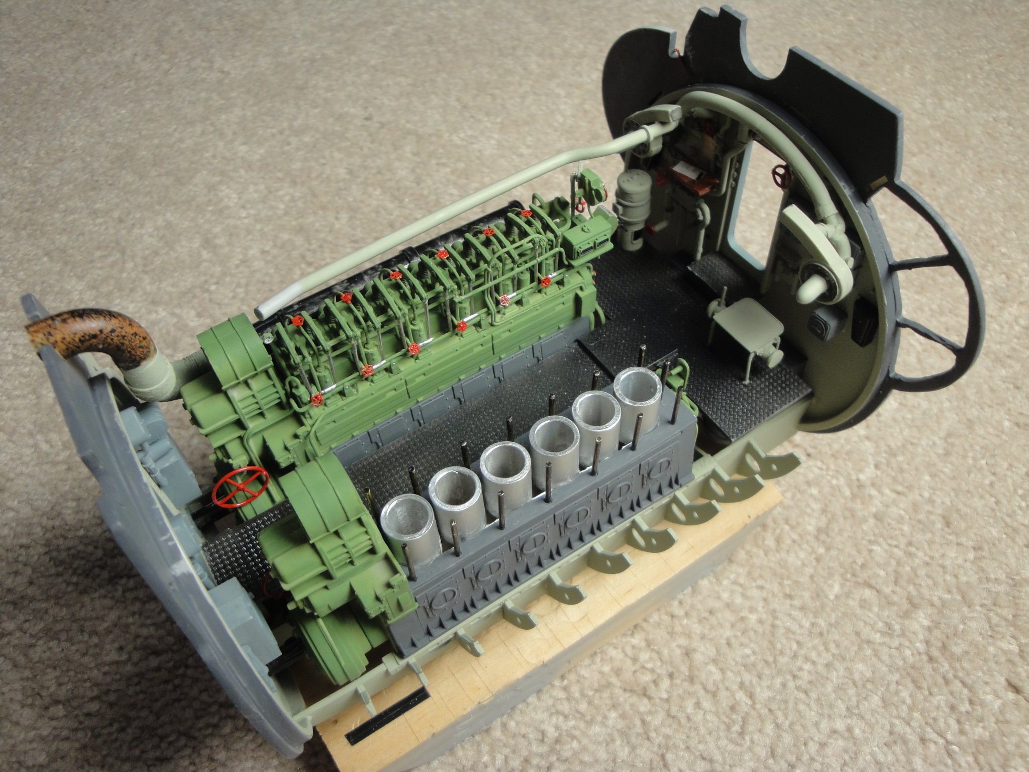
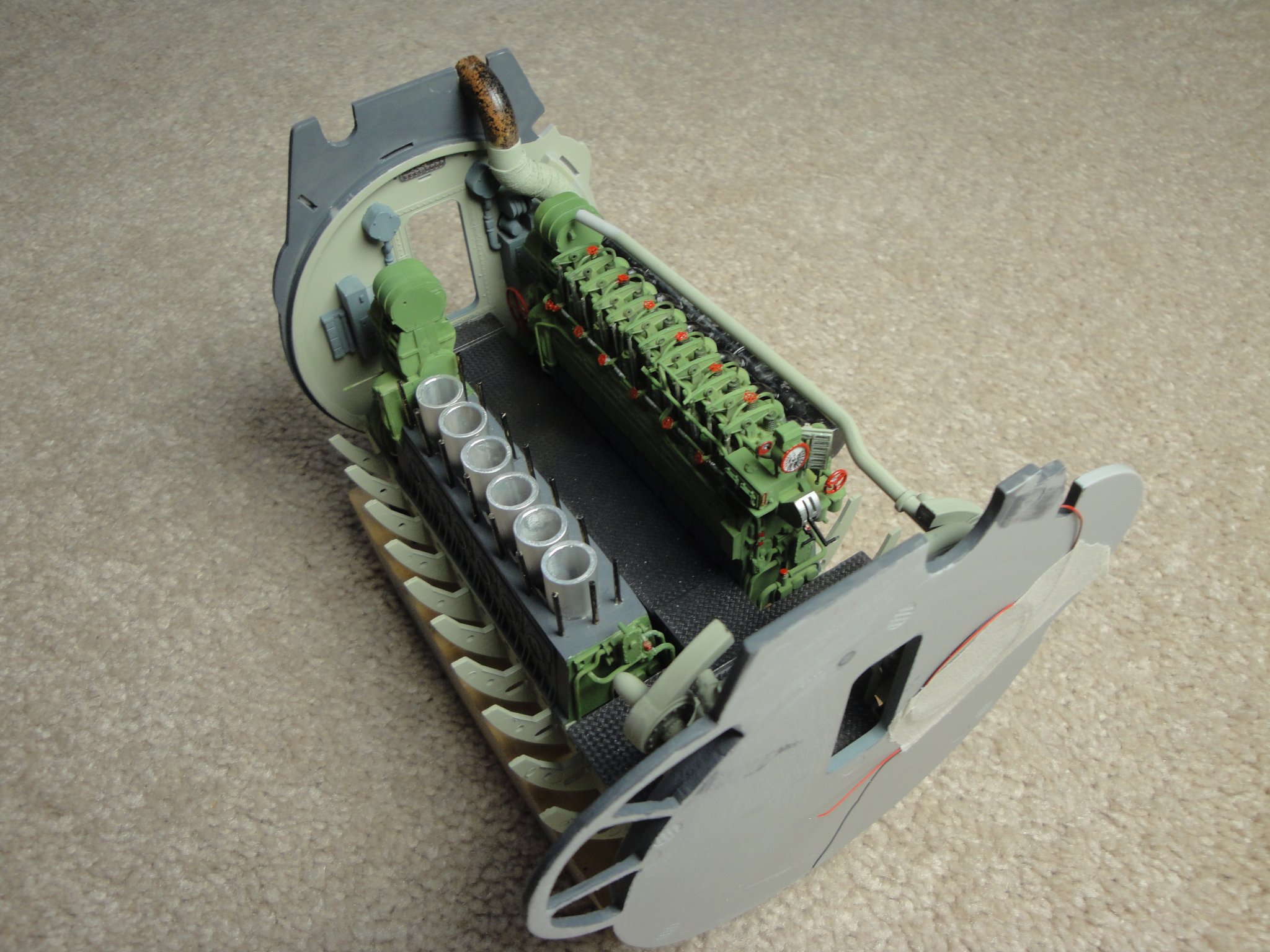
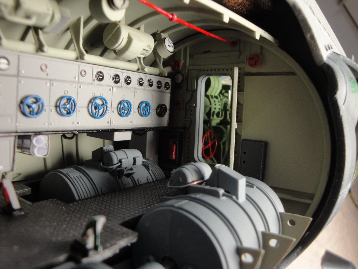
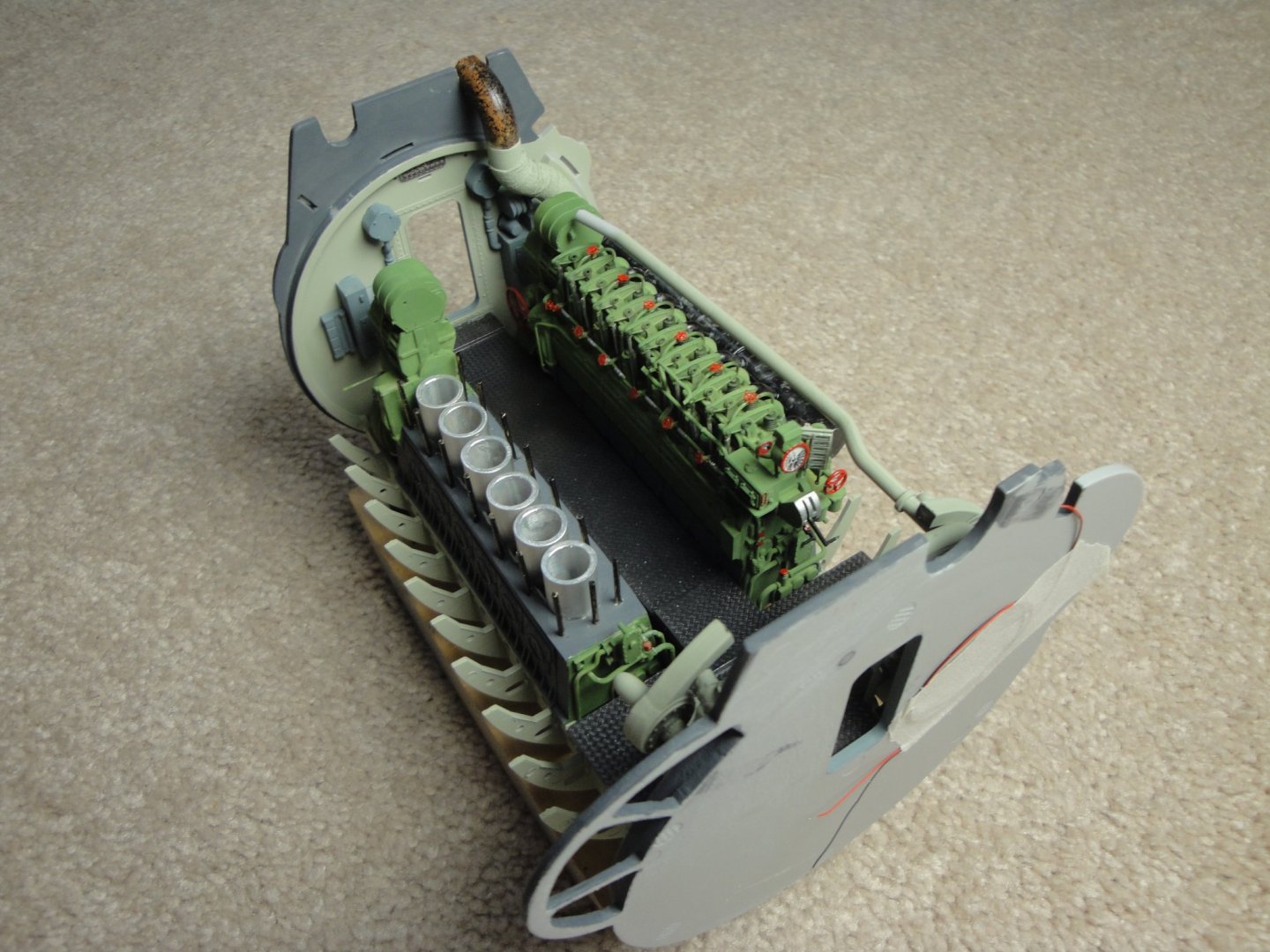
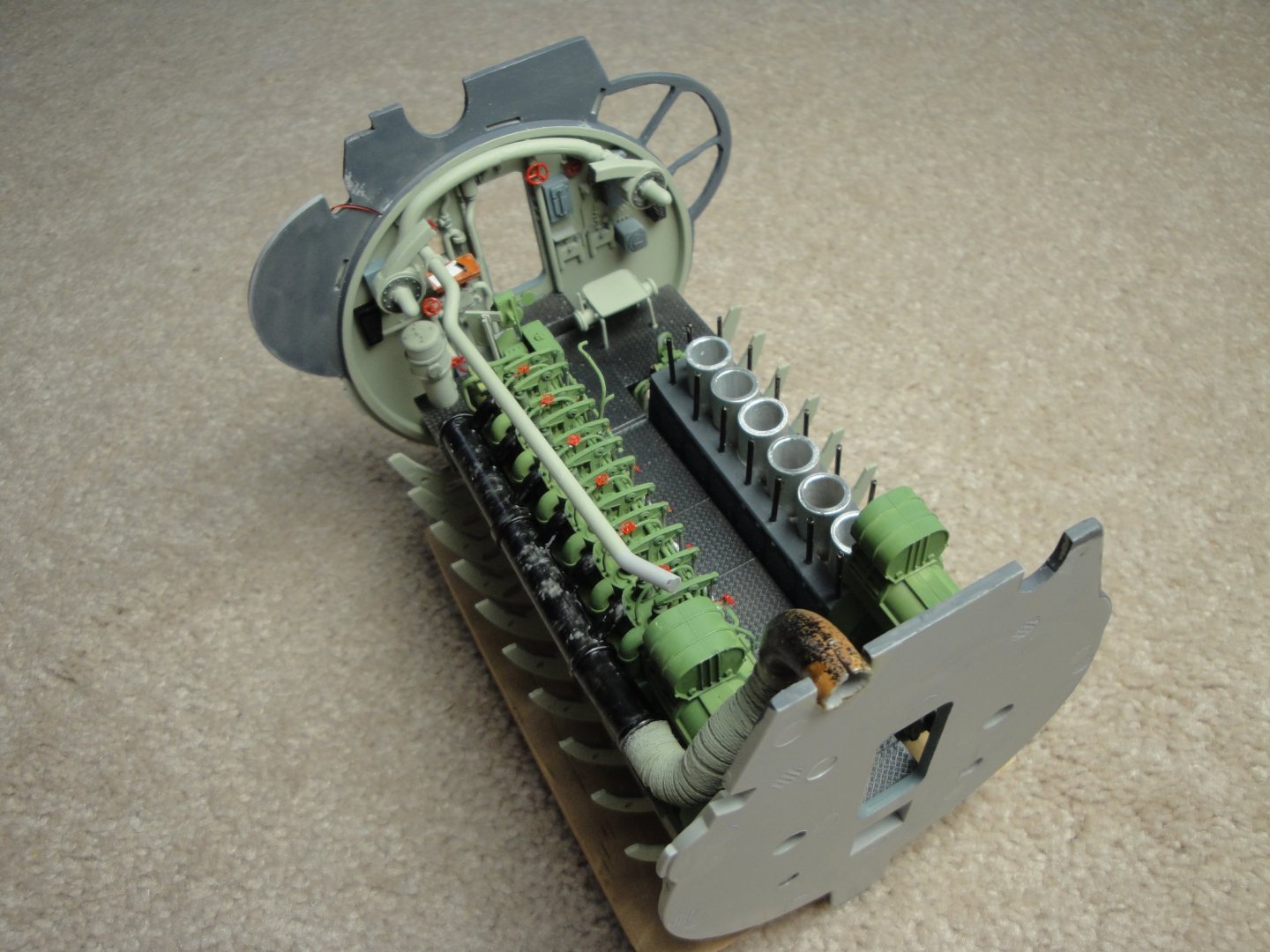
We now have reached a point, when serious decisions must be taken. Assemble or not assemble? I am sure you all agree that it needs to be put together. Therefore, here are a few pictures: And the silly pictures... I hope you have enjoyed being reduced to 1/48th scale and taking a tour of that interesting compartment. Next time, we seal it with the ceiling..... but first some crews.... Yves


- 760 replies
-
- 20
-
-
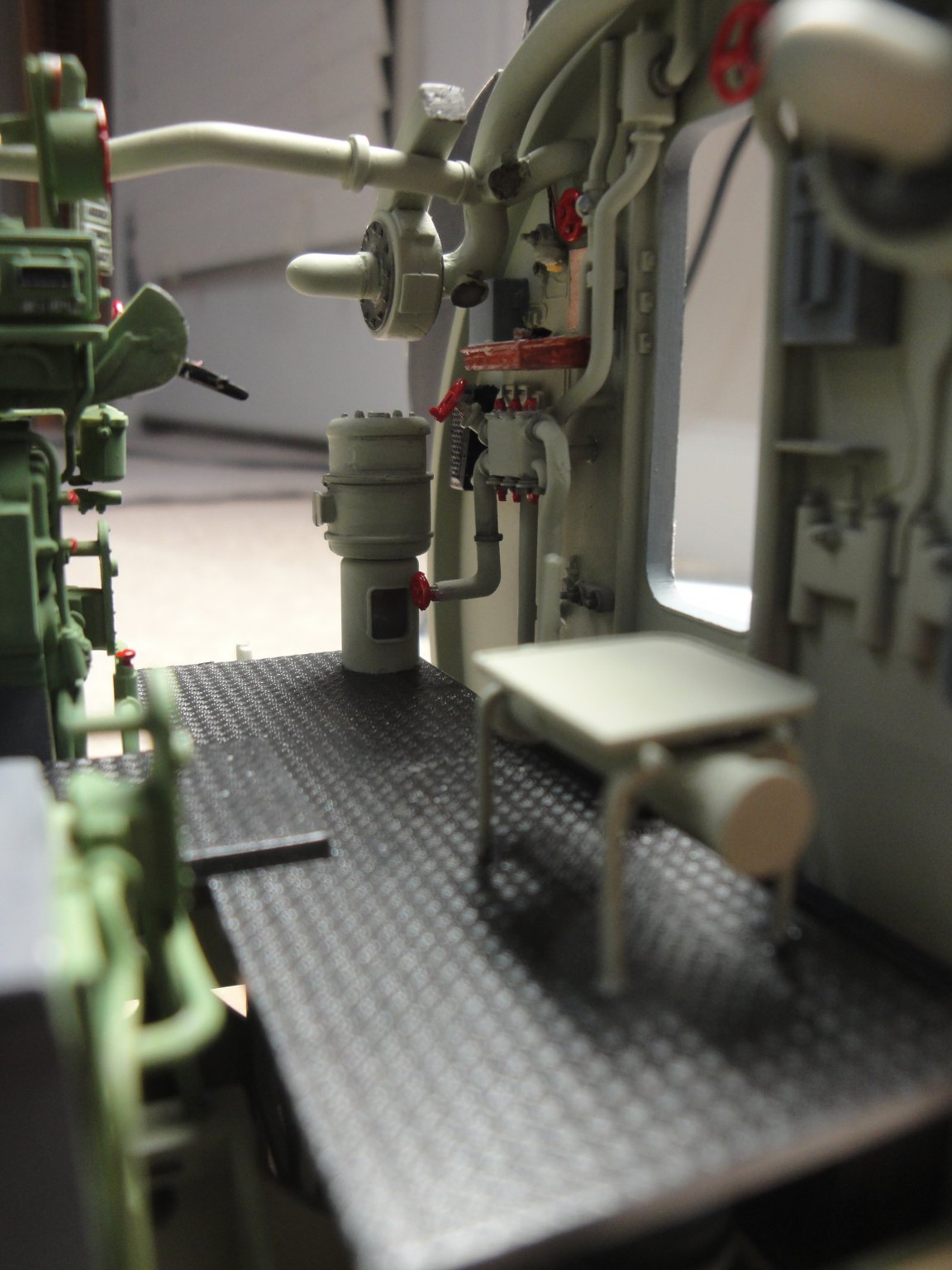
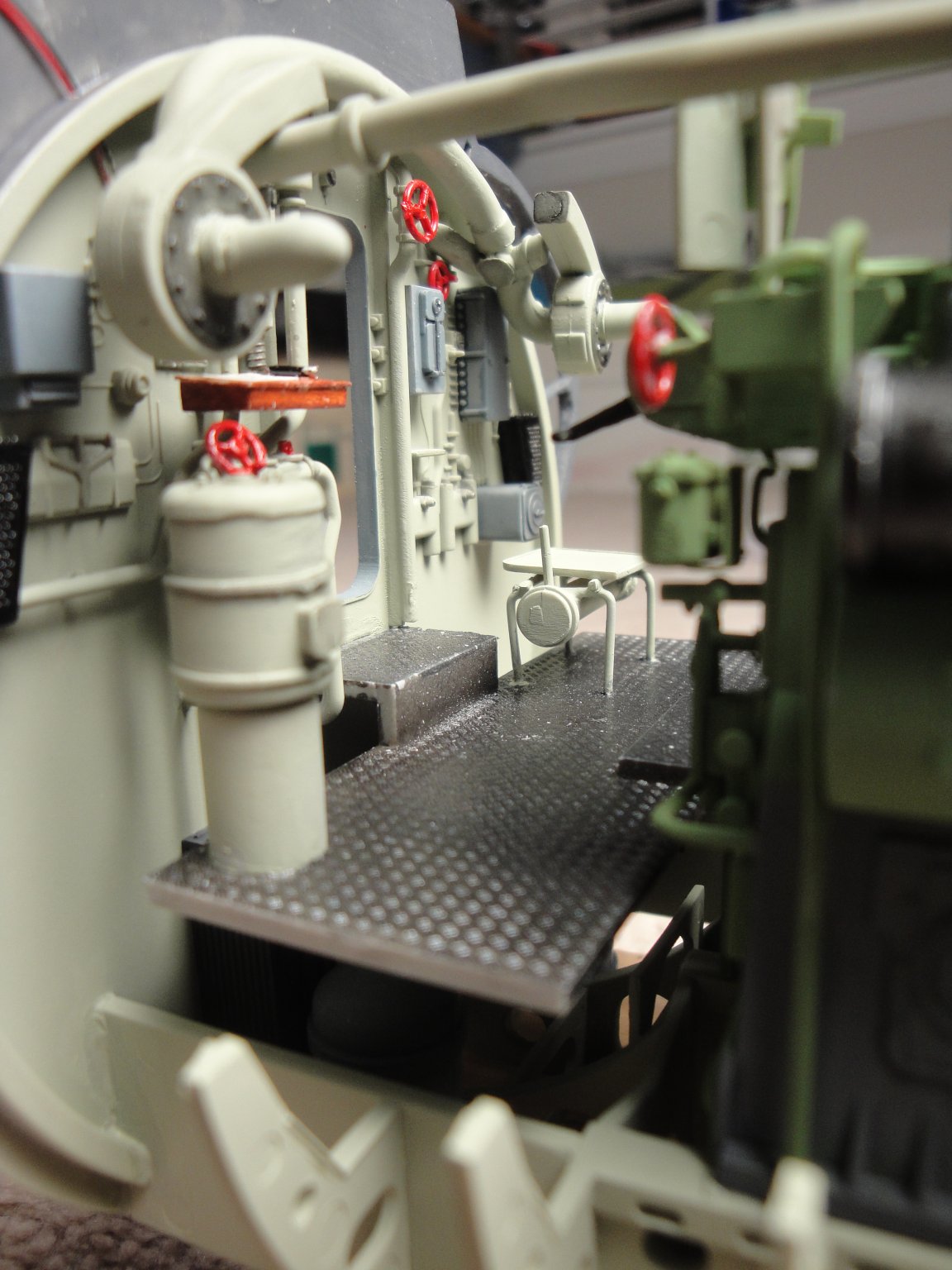
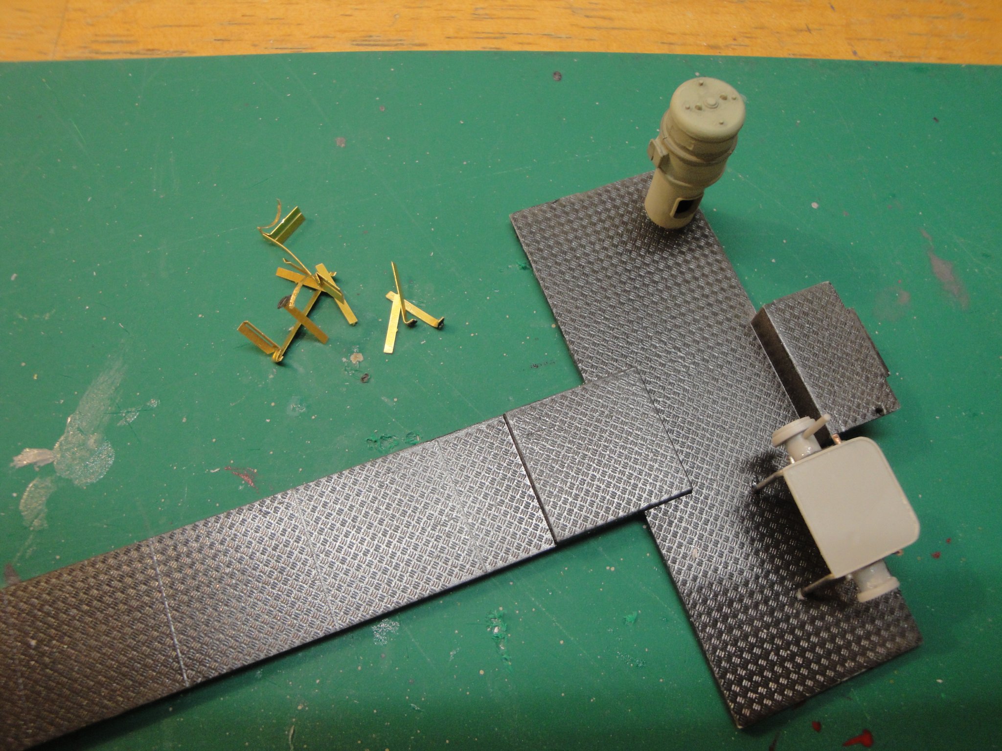
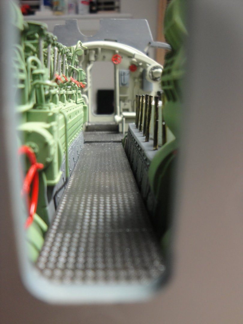
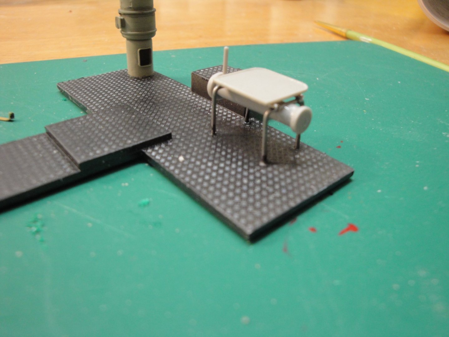
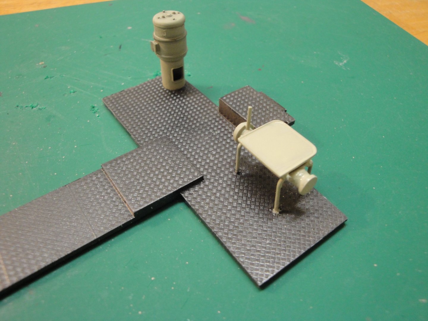
Moving on with the walkway. Basically just a few parts according to Trumpeter, but a nightmare to assemble..... That table made of photo-etched parts is ridiculous and a challenge to the nerves. You can see the result of my assembly on the picture..... a disaster. Sometimes, it is good to show the casualties of modeling, as most builders only post their success: Trumpeter should have offered a table made of plastic parts and it would have been so much easier to assemble. instead, I decided to do mine with the "legs" of electronic components, bent and inserted in the walkway, after drilling #60 holes. A lot easier and so much sturdier. Quite realistic too: When all is painted and said: I have no idea what this table is used for. Is it used for mechanical jobs? Don, can you chime in and enlighten us? Yves

-
Don, you truly are the expert. I may have to change it.... I am sure the rivets counters will argue with my choice..... Yves
-
Most likely, I don't think they had ball pens yet and I doubt they used fountain pens inside a submarine. Yves
-
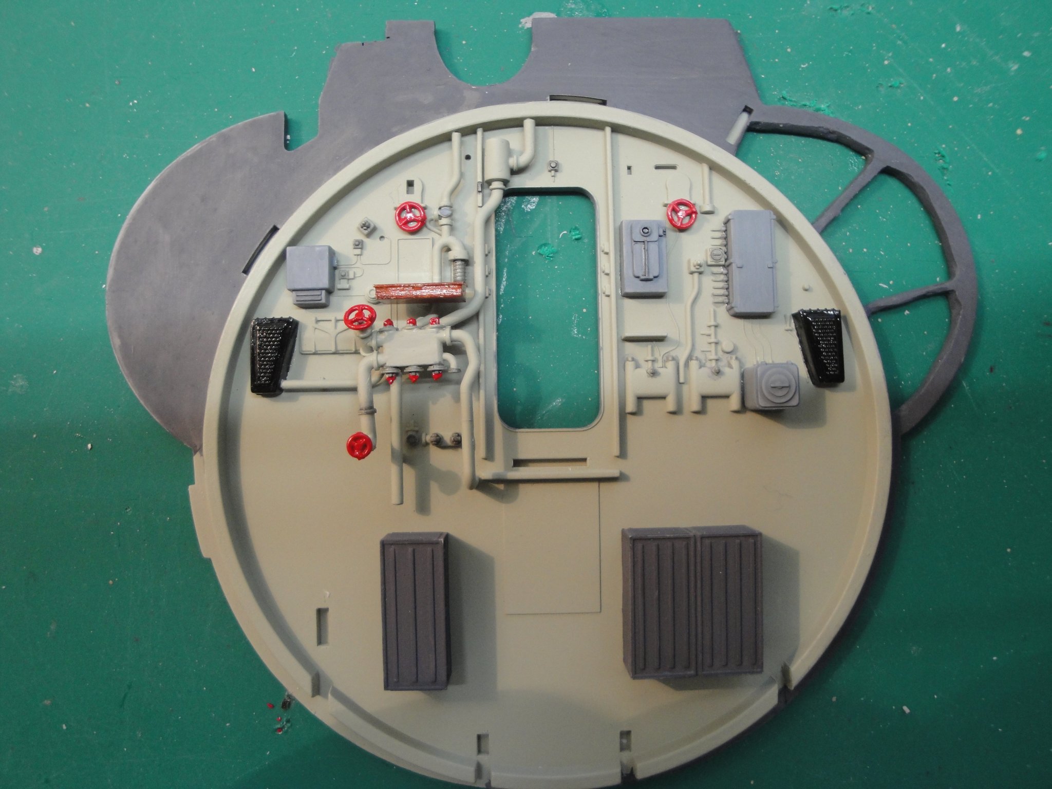
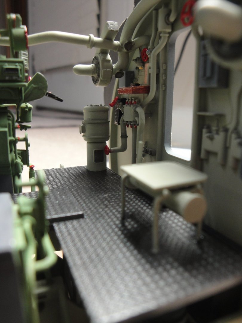
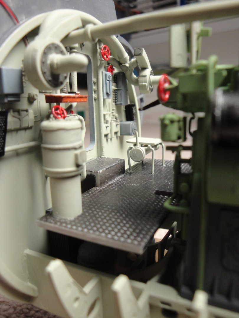
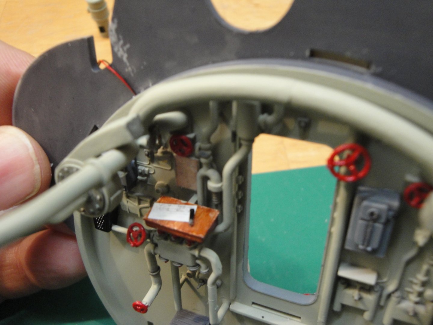
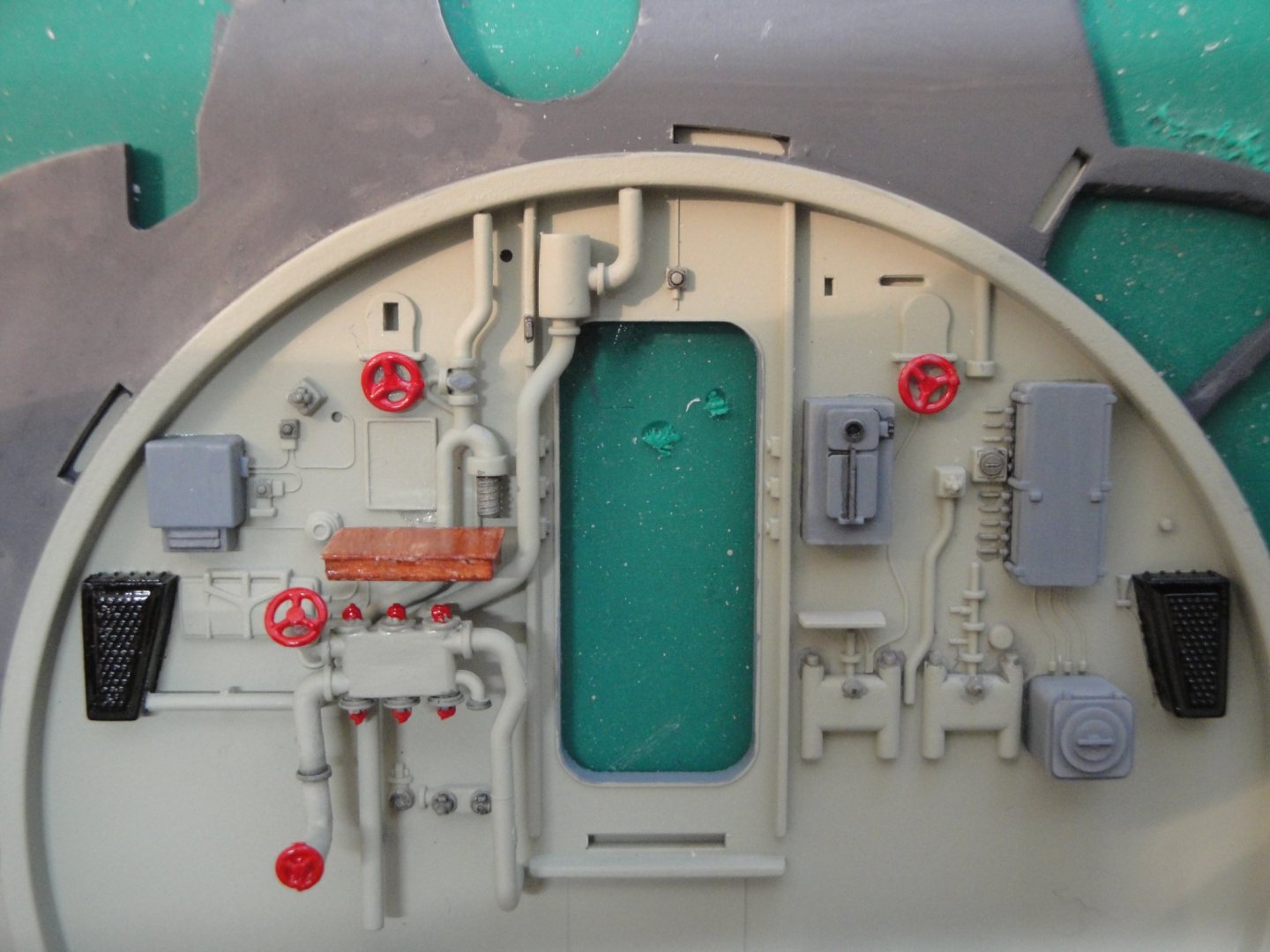
Still toying, yes literally, with the front bulkhead. I have decided with some spare parts to replicate the fan system, used to bring fresh air and extract used air from the inside of the pressure hull. Of course, Trumpeter does not provide the second set of fan/turbine as well as some of the pipes and it is very regrettable. It takes a lot of butchering and gluing of the pipes to get to a decent and matching results. I have also added the electric motors which are driving the turbines, as these parts were not designed by Trumpeter. Please do not ask for the electric wires of the fan motors.... Close up on the little wooden desk. Barely visible against the wall, is a German print indicating essential operations of the Diesel engines. On the wooden desk, is a schematic of some of the numerous pipes circuits and a large pen. Not yet visible, is a small light to the left of the red control hand wheel. The micro wires are coming above on the bulkhead. We now have quite a few pieces to put together. However, before the final assembly, I still have to work on the walkway. Yves

- 760 replies
-
- 22
-
-
Thanks Don for these complement of information. Obviously, Trumpeter did not know about these peculiarities, or decided to skip them. Yves
-
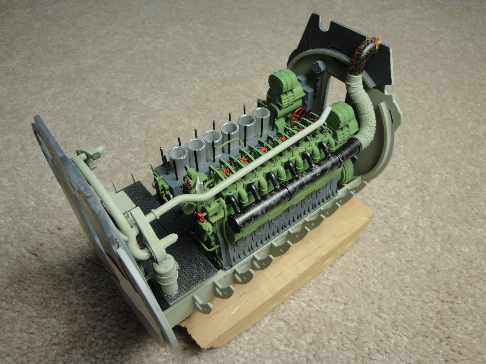
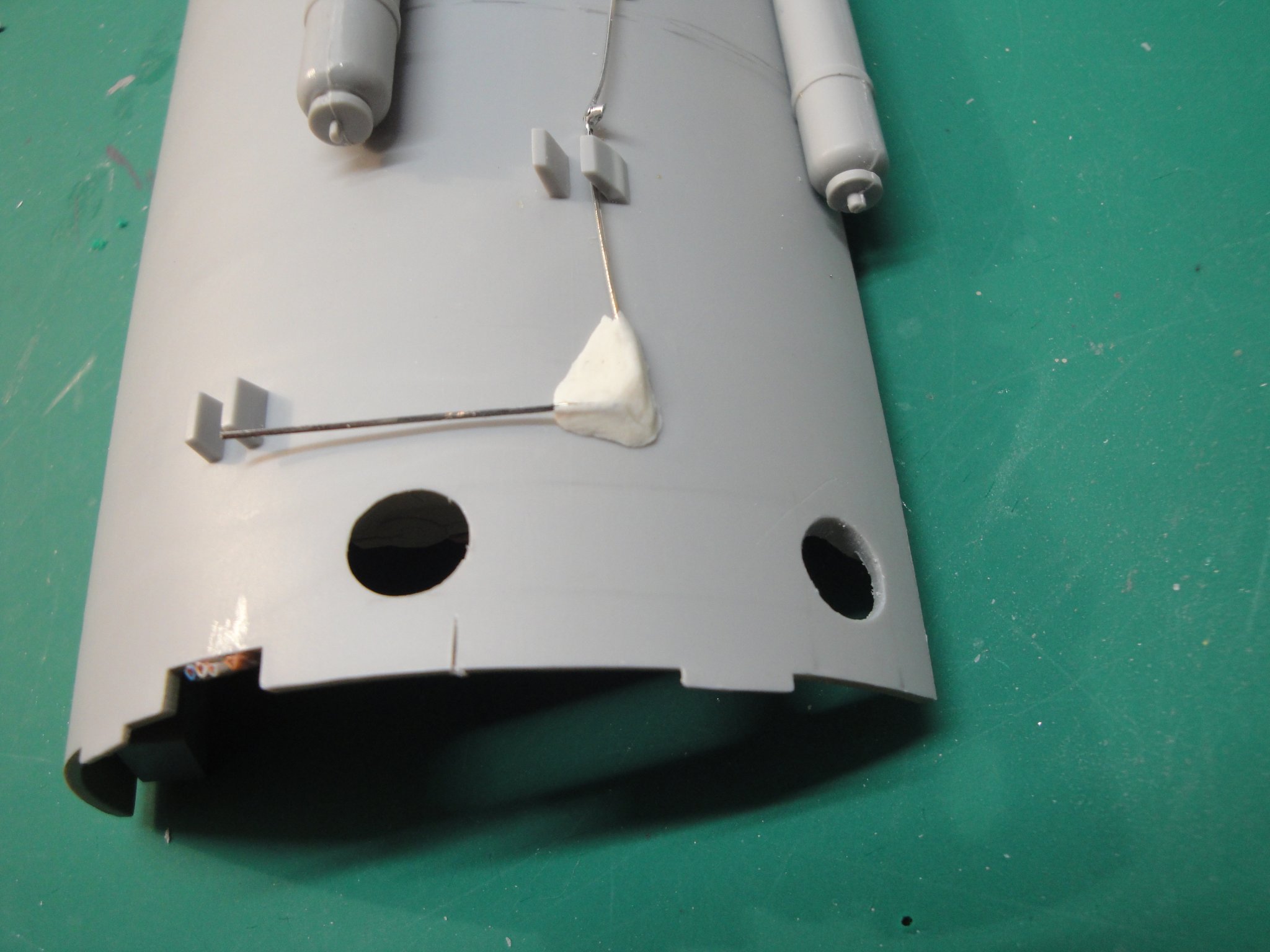
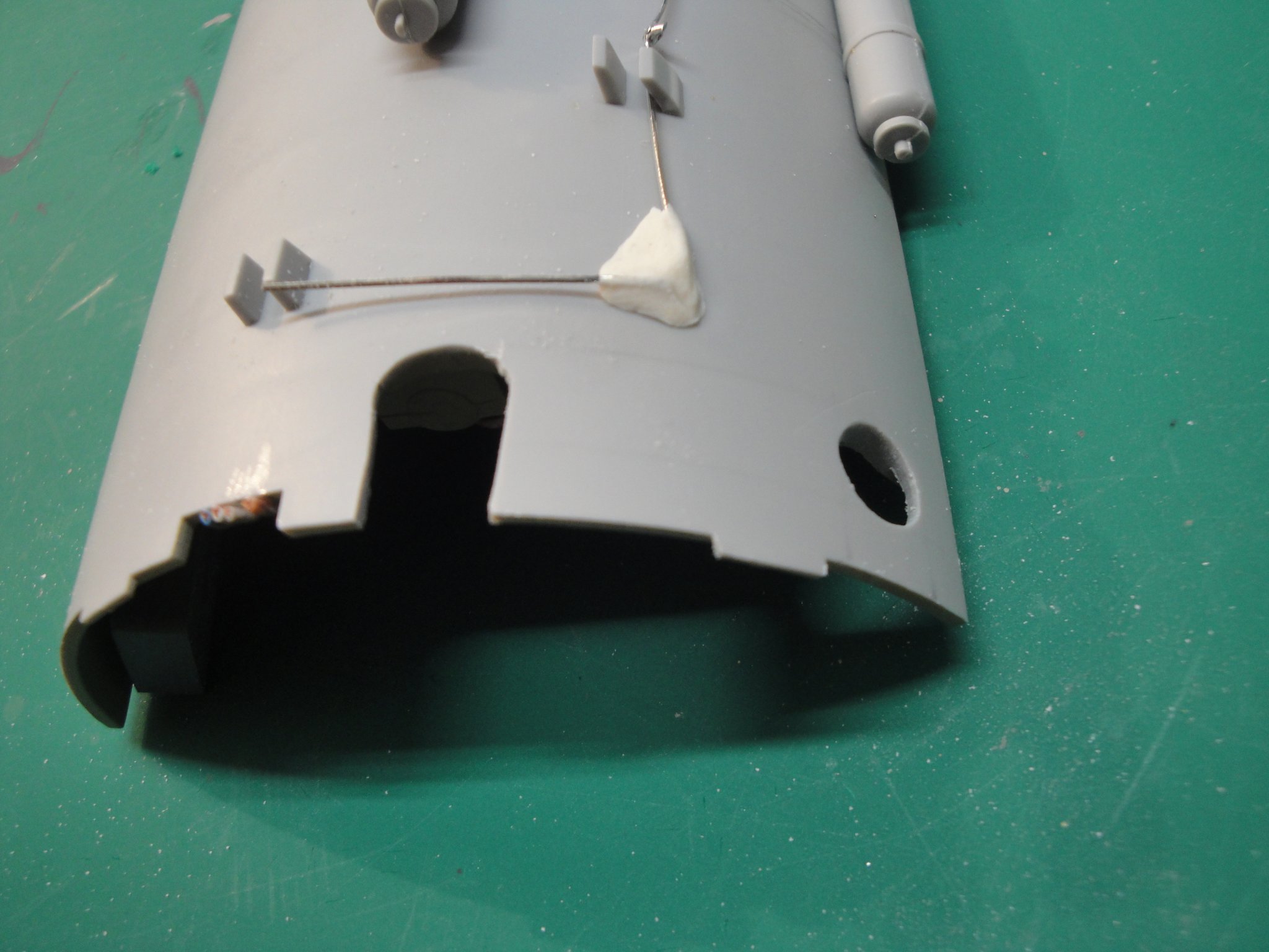
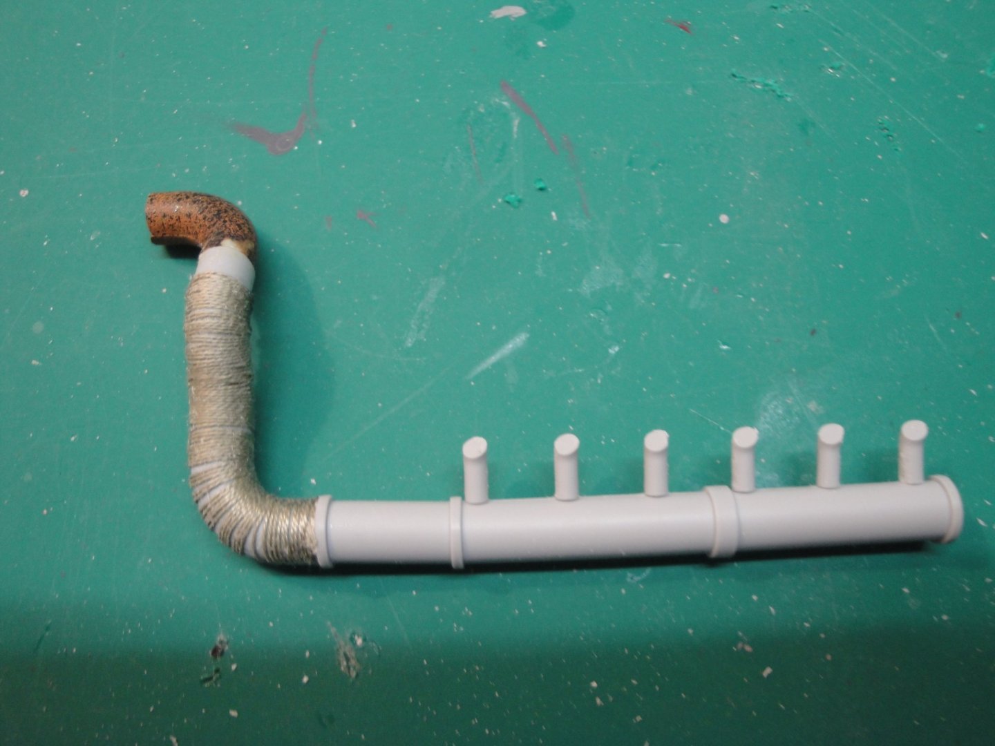
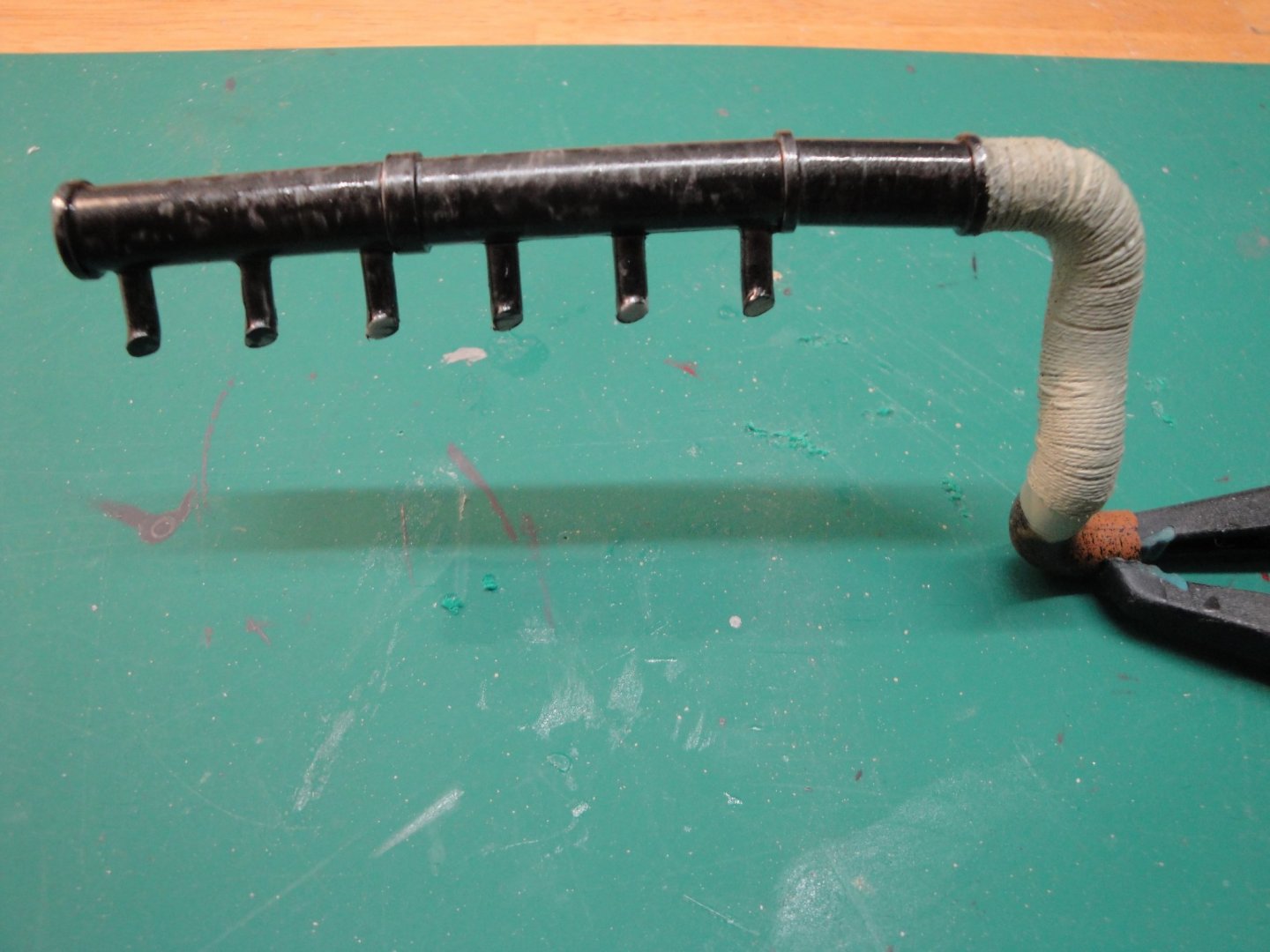
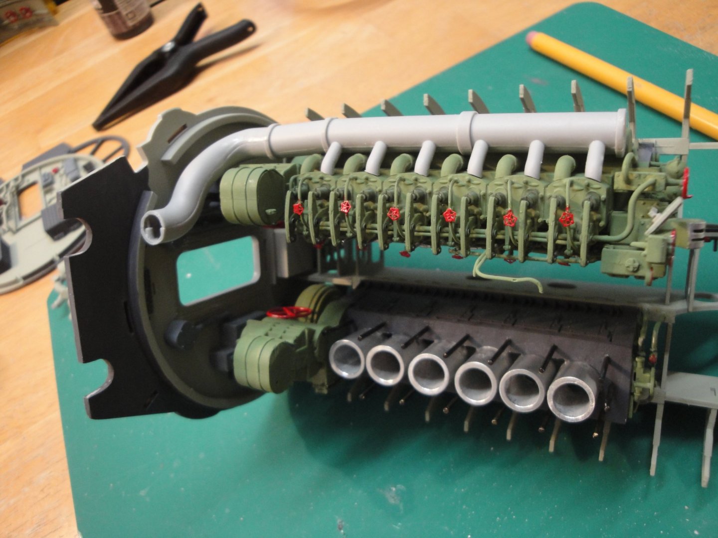
I have been working on the exhaust system of the Port diesel engine. Most of it will be completely invisible, but I have the satisfaction to know that it is there.... First, the ceiling had to be slotted to allow the fixed exhaust pipe to go through. In fact, it is almost impossible to present the piping correctly, if you plan to use the hole provided by the kit. Below is a picture before: And after: The right hole will be used to insert just the elbow, from the top, and as such does not need to be slotted. The exhaust is built by carefully gluing the pipe to the ramp: The tube is coiled with some heavy cotton thread to simulate the insulation band, that was used to insulate against the noise and heat. Finally, after gluing in place the exhaust: Most of it is frankly invisible. So, let's enjoy it as we will never see it again, once the ceiling is installed. Yves


- 760 replies
-
- 20
-
-
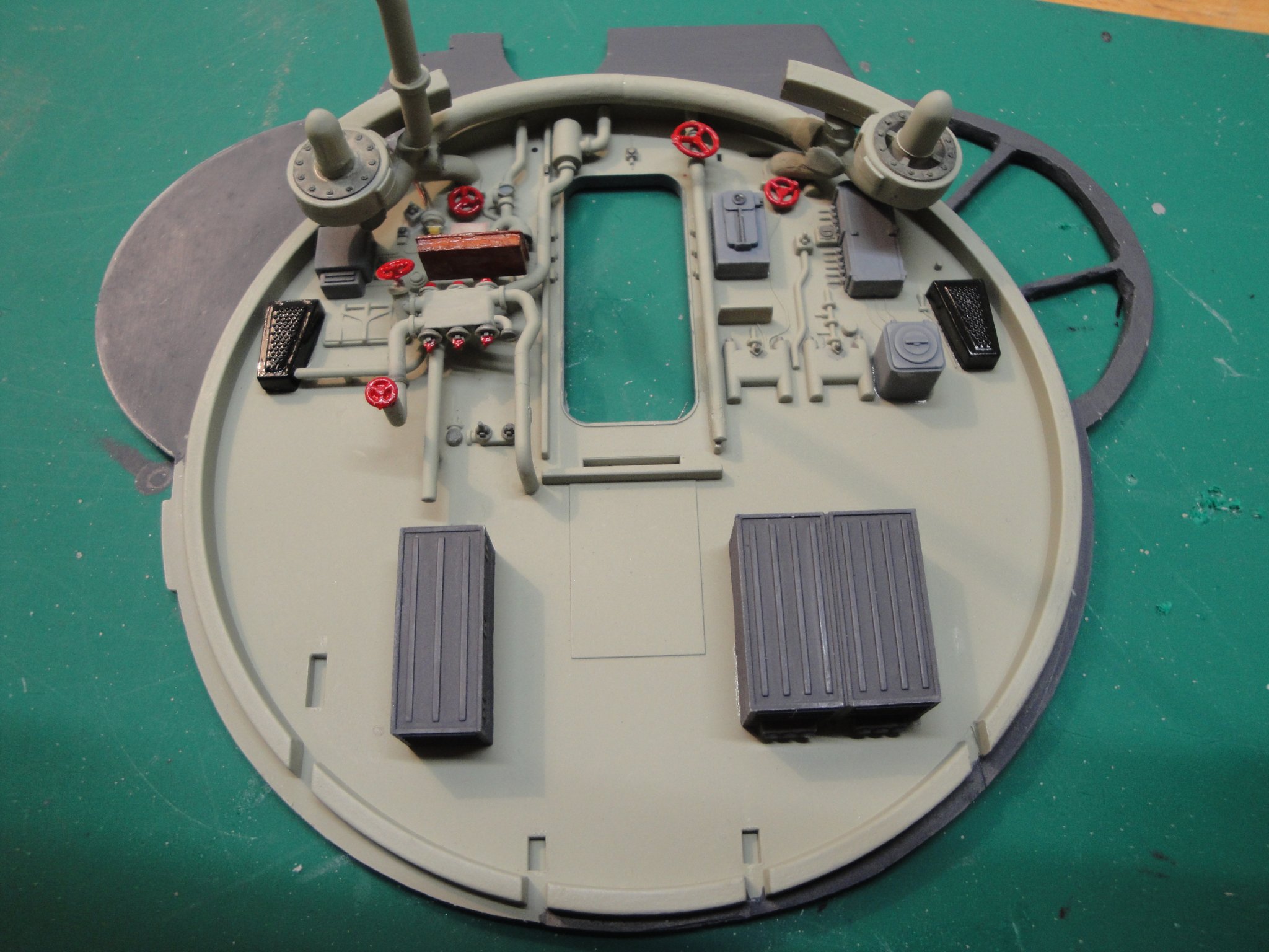
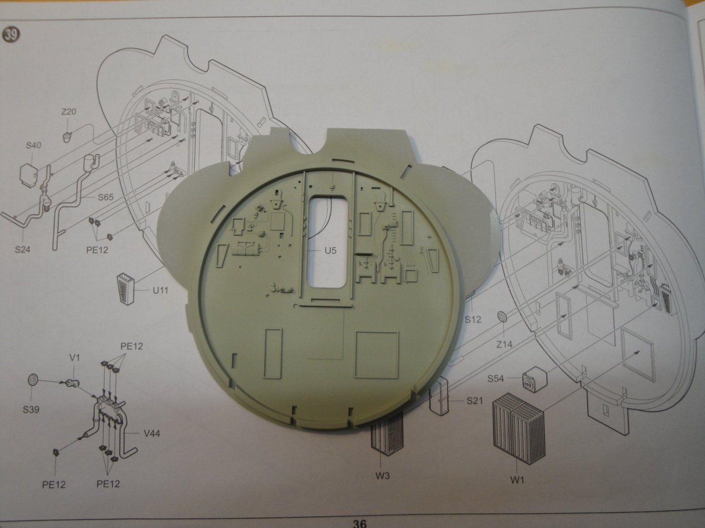
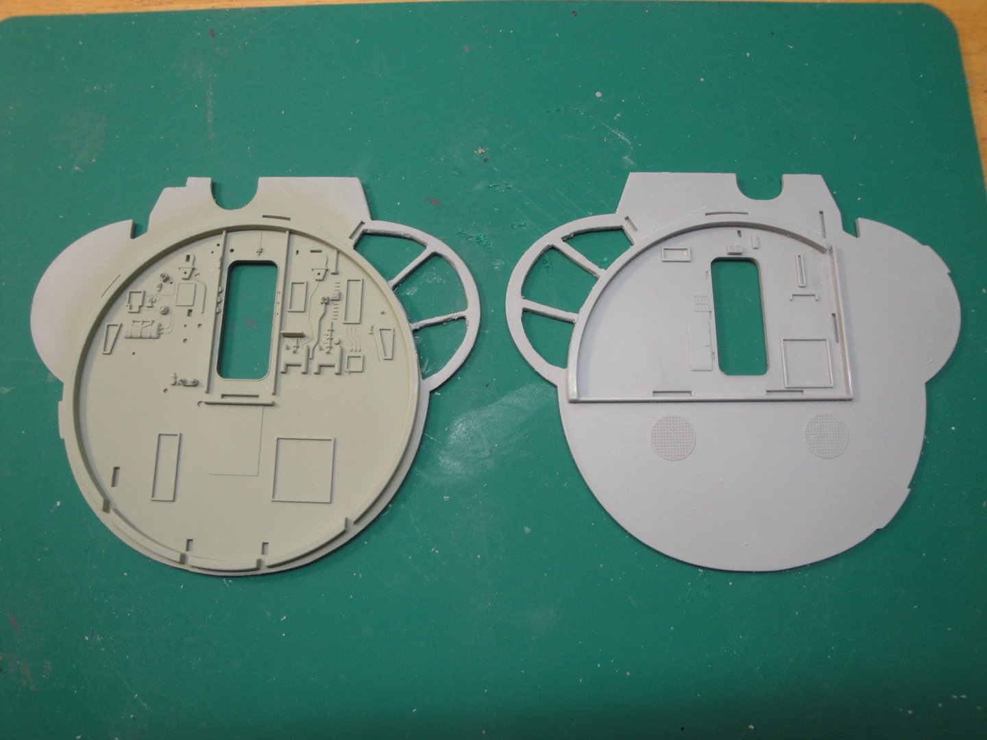
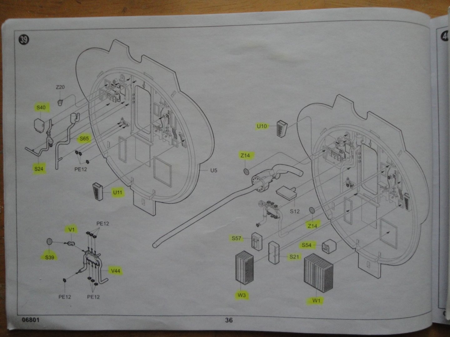
We are coming soon (hopefully) to a conclusion on the Diesel engines compartment. I am now working on the front bulkhead: The bulkhead is cut on the starboard side, to show the various tanks, since this section will be visible from outside. And to make sure that the rear kitchen bulkhead matches that one, we cut them together: And then, it is the delicate assembly and endless touch-ups with paint, to make it look decent and realistic: A few more details, a light above the desk and we will move to the walkway assembly. Yves

- 760 replies
-
- 19
-
-
Enzo Ferrari by CDW - Tamiya - 1:12 Scale - PLASTIC
yvesvidal replied to CDW's topic in Non-ship/categorised builds
I have the McLaren F1 from Model Art. This is not a kit, but is at the same scale as your Ferrari. Made of metal, plastic and rubber parts. I bought it in Europe about 25 years ago, when the car came out. Yves