SJSoane
-
Posts
1,651 -
Joined
-
Last visited
Content Type
Profiles
Forums
Gallery
Events
Everything posted by SJSoane
-
 Alexandru, Beautiful work. I will return to this as a good tutorial when i get to that stage. Best wishes, Mark
 -
Hi Ed, Fun to watch a 19th century build, after so much focus on the 18th century. Someday, you might offer some thoughts about how shipbuilding changed between the Naiad and the Young America, above and beyond the differences due to naval vs. commercial. Did they get more efficient in use of materials or assembly as time went on? Best wishes, Mark
- 3,618 replies
-
- 1
-

-
- young america
- clipper
- (and 1 more)
-
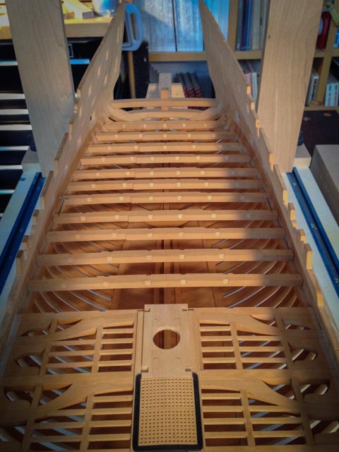
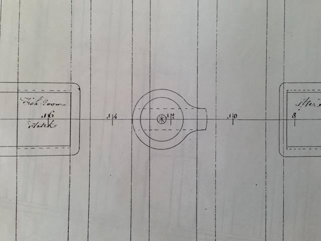
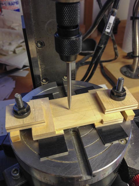
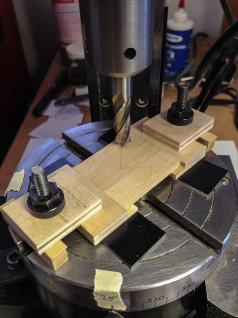
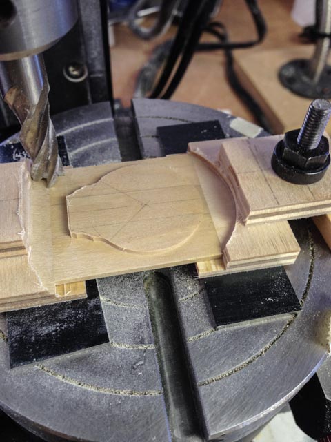
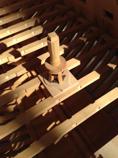
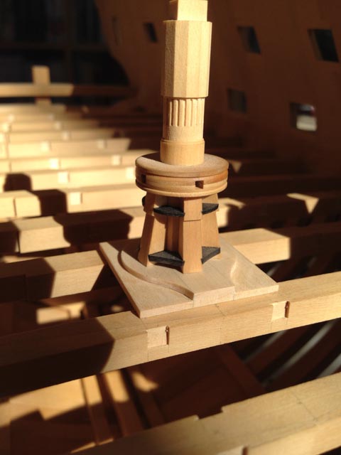
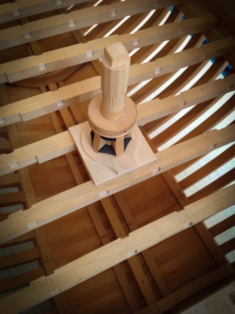
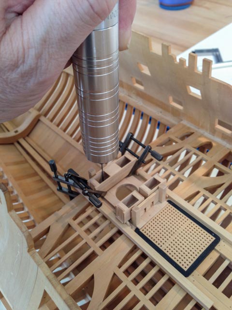
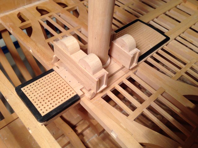
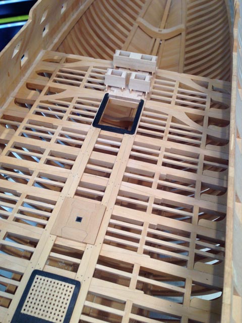
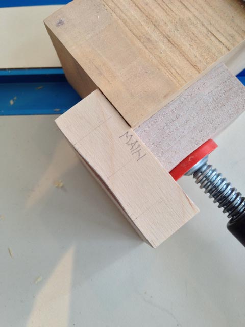
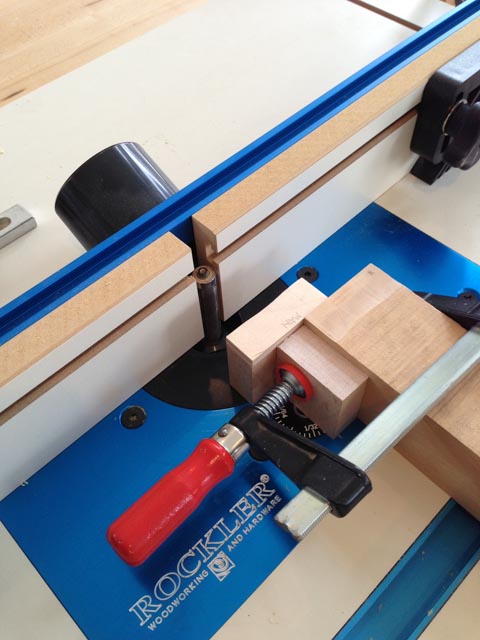
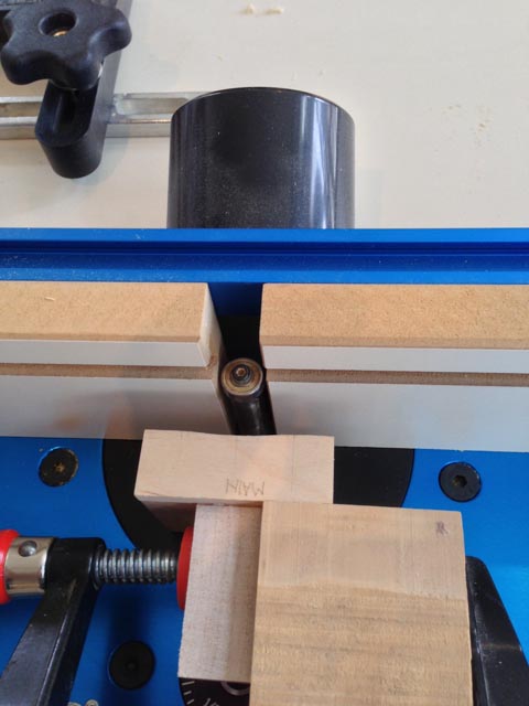
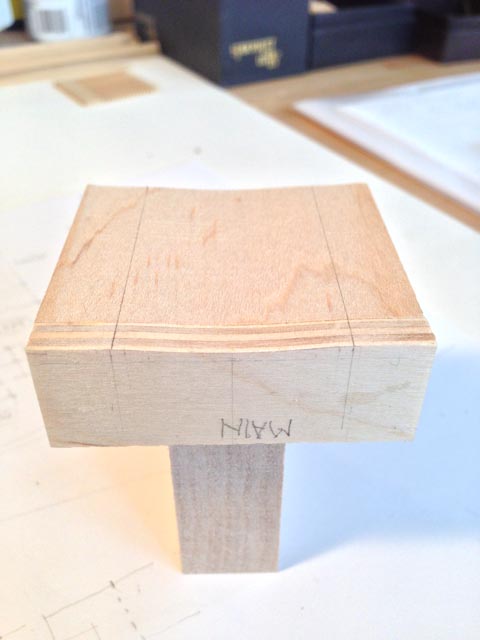
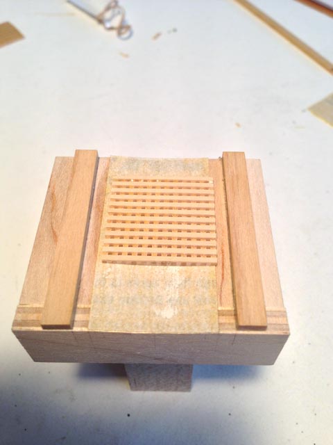
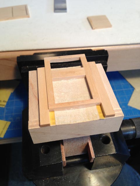
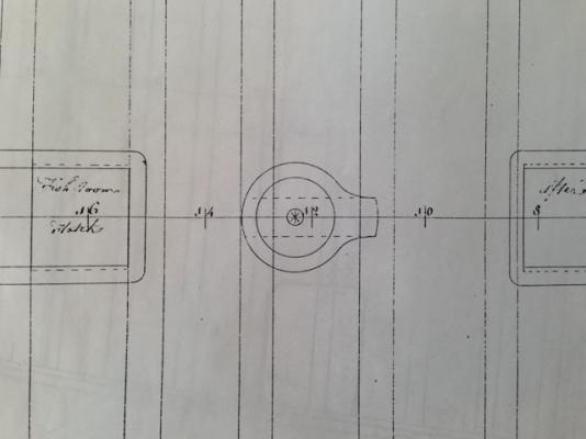
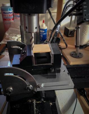
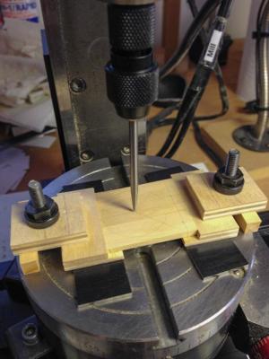
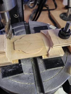
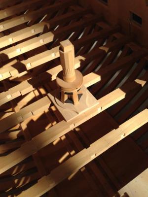
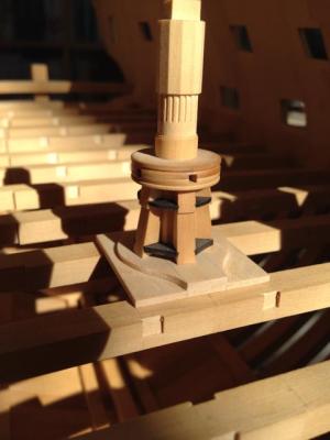
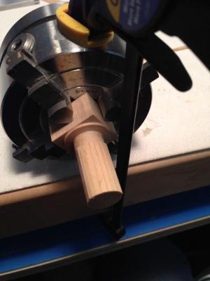
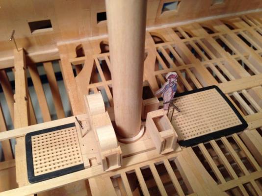
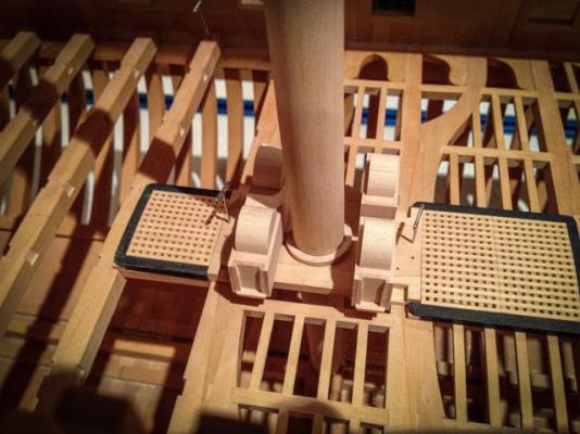
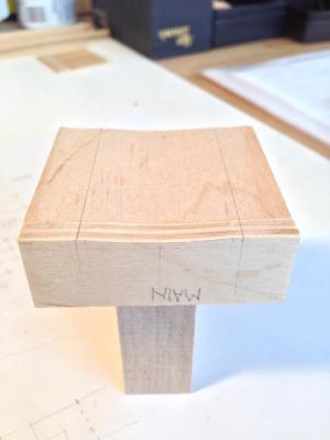
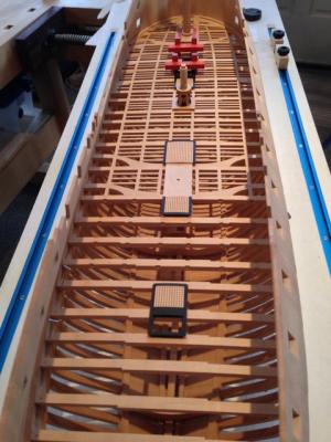
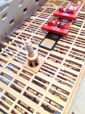
HI everyone, Druxey, remco, EdT, Michael, blue ensign, spencerC, thank you for your kind comments. And many apologies for not replying sooner; work is really getting in the way of the shipyard these days! After finishing up around the main mast, I sat down one day to finish up the mortises in the beams for carlings. I was inspired by Gaetan, who advised me that doing the same thing over and over, and in a logical order, is efficient, meditative, and it improves one's skills. So I told myself I was not leaving the shop until the remaining mortises were cut. It was hours later, but very satisfying to see all of these after a number of years of looking at the deck without mortises. Gaetan was absolutely right in his advice. i processed each step on all beams, then went back to the first for the next step. It build a great rhythm. I then turned my attention to the step for the main capstan. You will see in the photo of the original Admiralty drawing that this was very cryptic. How does a circle sit on the beams, and how does one plank up to the circle? I then came across a photo of the Ajax cut away model, showing the entire gun deck. It showed this step as a raised surface in a rectangular plank. After reviewing Steel, I decided that it was really a central, thicker plank, with thinner planks on either side to make up the width across the two central carlings. You can see the dotted line of the three planks in the Admiralty drawing. The projection at the front of the circle is to provide a surface for the pawls, which pivot from the fore edge of the projection and can be kicked under the capstan when wishing to stop rotation either way (another fun part to make some day). I also remembered from David Antscherl's book that the top surface of the capstan step would have to be parallel to the keel, not parallel to the deck. This is because the capstan turns on an axis perpendicular to the keel, and the aft side would be higher off the deck than the fore side because the deck slopes at this point. Then it made sense that the circle would provide the surface parallel to the keel, and the remainder of the step would be flush with the decking and therefore parallel with the deck, to avoid places to trip when working the capstan. Very ingenious design, when you finally figure out what they were doing. I had fun with the mill making this. First, you see the step sitting in a vise on the tilting table, having one surface milled down at 1 ½ degrees to match the difference between the deck angle and a line parallel to the keel. Then you see the rotating table, with the step mounted on top. I first used a Starrett wiggler on the central hole of the rotating table to align it with the mill spindle. Then I clamped the step on top, using a Starrett wiggler to locate the center of the step circle also under the mill spindle. I then used a mill cutter to cut a perfect circle around the edge, leaving a flat base with a raised circle at the 1 ½ degree angle. I used chisels to clean up the serpentine curve on either side at the fore end. I stole the capstan from midships for the photos. I now need to build the second capstan.... Best wishes, Mark


-
Thanks, Ed, I have really missed keeping up with the website. I did manage to get a copy of your latest book, however. It is a masterpiece! I am referring to it regularly as I ponder how to undertake certain tasks on the Bellona. A masterpiece! I also see that you have started a new build here. I look forward to following it with as much enthusiasm as I did with the Naiad build. Best wishes, Mark
-
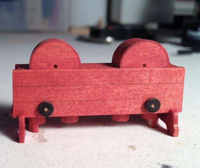
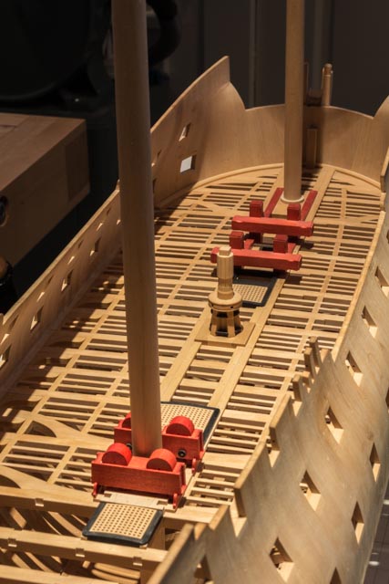
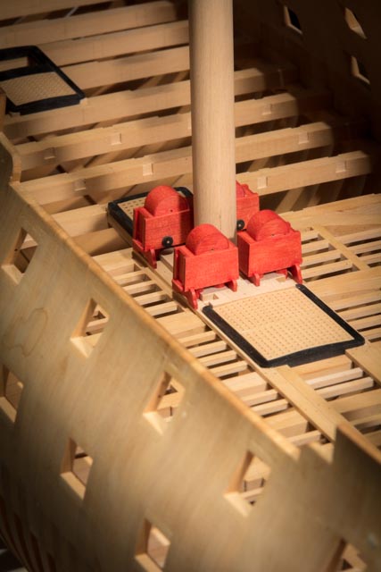
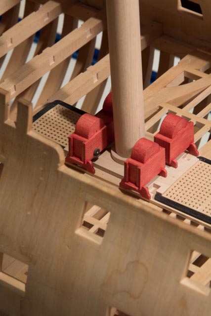
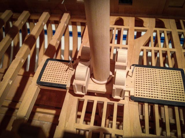
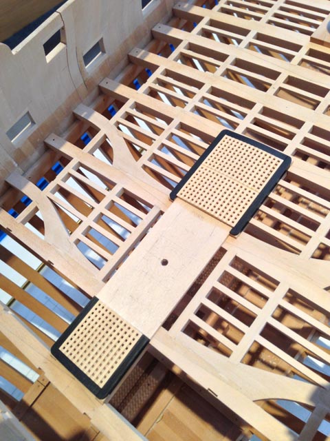
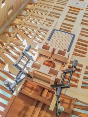
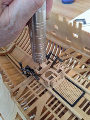
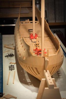
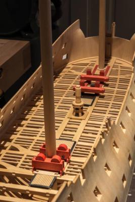
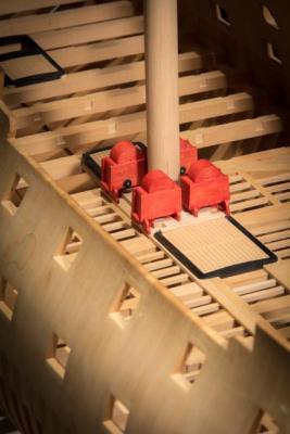
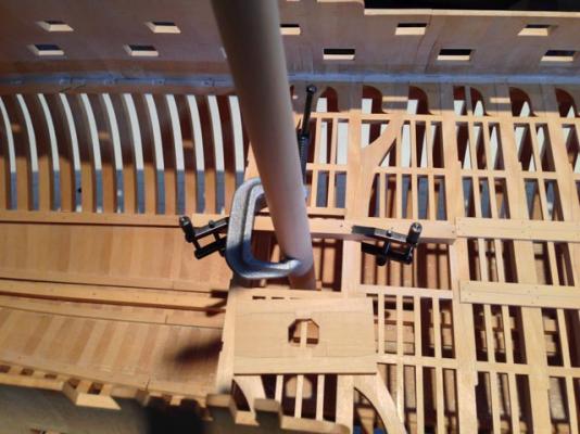
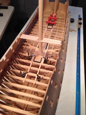
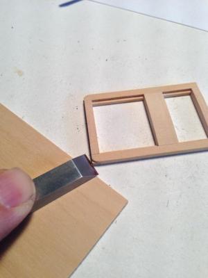
Hi everyone, After building the cisterns, I discovered how difficult it was to locate them square to the mast partners, and the right distance from the mortises for the jeer bitts. So I built a little spacing jig, slotted into the mortises in the partners and with a spacer the right distance to the cistern. Once the cisterns were clamped in place against the jig, I was then able to drill down with a Foredom through the stub pump tube tops, for location pins. I also used this jig to align the hoods so that the future pump handles running through the hoods will line up with the inner face of the bitts where the rhodings will be attached. I made a little sliding joint on the bottom of the hoods so that they could move a little on the cistern athwartships, to allow precise alignment. And finally, in keeping with the color scheme of the dockyard models that so I admire, I stained the cisterns red, to match the riding bitts. In the closeup, you can see the stump tube tops, and a simplified drain plug. The bearings are still to come. The long shots show how nicely the red accents are showing up along the length of the hull. I know color is not to the taste of everyone, but I like the overall effect of colored accents against the natural wood. I am being pulled back to work issues, so I may not be able to work and then post for a while. It was a nice run while it lasted.... Best wishes, Mark


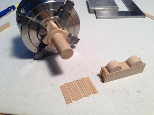
-
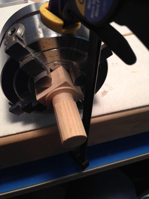
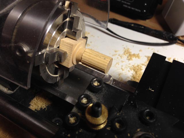
Hi everyone, I then started on the pump cisterns. I had originally planned to run the pump tubes down into the hold, but after trying some mock-ups, I reminded myself that my stylized dockland framing system really does start everything above the gun deck for a reason. Without an orlop, a well, or anything else along with the tubes, I decided they would look silly all by themselves down in the hold. So I followed the lead of the HMS Princess Royal in the Legacy of a Model book, and built stub tube tops between the partners and the bottom of the cisterns. I pondered how to build the coopered covers on the pumps; at 3/16" scale, a ¾" thick shell was too thin to get good coopered joints. So I cheated a little. I turned a wood blank, and then layered the ¾" pieces (plus a little for trimming) on the blank. I then re-chucked this, and turned the assembly down to final size, leaving a clean and accurately sized hood. I cut off the lower half of the blank, leaving the half round hood. They aren't hollow, but I didn't build the pump inside anyway... Best wishes, Mark


-
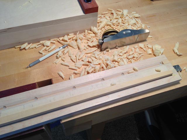
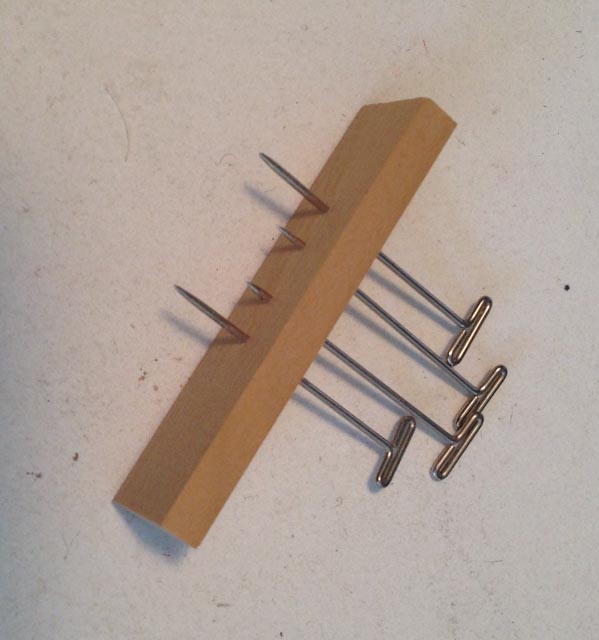
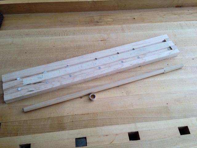
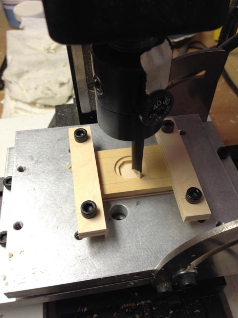
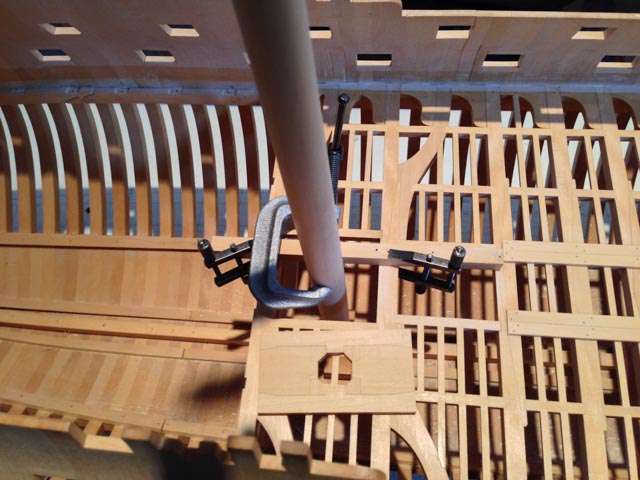
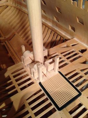
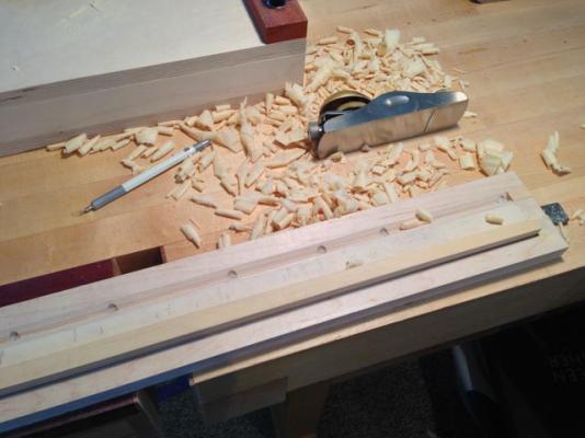
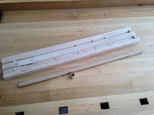
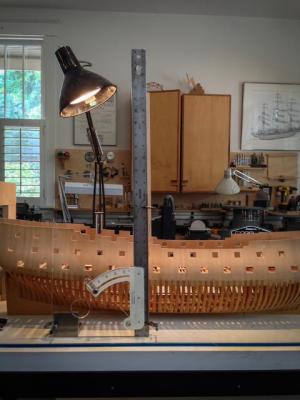
Hi everyone, I was taken away from the shop by work for a number of months, and I have slowly been starting up again. I'll post a few updates. I focused on the mainmast and its immediate area. Here I am showing the mainmast under development. The basic construction is taken from Antscherl's Fully Framed Model Vol. IV, which planes a blank to an octagon, and then is smoothed round with sandpaper. I developed a couple of jigs to help. First, I put some nylon screws in the bottom of the jig for planing 4 and then 8 sides. As the mast is tapered, it kept rocking in the jig. This way, I can raise a screw underneath the blank to keep it level as I plane. Really helped. I also am showing a jig for marking the 7-10-7 proportions on the side of the 4 square blank; planing to these lines creates a perfect octagon. And rather than draw the proportions on each side, this jig lets me scribe the same on all sides, very quickly. I just hold the two end pins firmly against the sides of the blank, and let the middle ones scribe a line. It can accommodate the tapers and still keep the lines in proportion. I drilled the holes for the jig in the mill, which allowed me to dial in exactly the right distances to drill. I am also showing the setup for drilling out the partners for the mast wedge. The partners and the mast are both at different angles, and so I set this up on the angle plate on the mill to get an accurate bore. I built the partners up from the various parts, including the 45 degree chocks. And then I aligned the mast with a ruler on an adjustable drafting triangle to get the right fore and aft rake; and a holding jig at the top of the hull timbers to keep the mast centered. Fortunately, everything lined up on center. Best wishes, Mark


-
Hi Ed, I have not been able to keep up with the website for a number of months, due to pressing obligations outside the workshop. But I did check into see if you had completed the Naiad, and see here the good news. A virtuoso performance. Congratulations! I look forward to reading it again in Volume II. Is there a publication date yet? Best wishes, Mark
-
ancre Le Fleuron 1729 by rekon54 - 1:24
SJSoane replied to rekon54's topic in - Build logs for subjects built 1501 - 1750
Giorgio, Beautiful work. I especially like seeing your construction steps. I hope all is well with you. Mark -
Alexandru, I have re-done a few things, and know how painful it is. But the new line for the wale looks much better! Mark
-
Hi Michael, I just got back after an absence and caught up on your build. Fantastic! I am ready to take a class from you on metal working. Best wishes, Mark
-
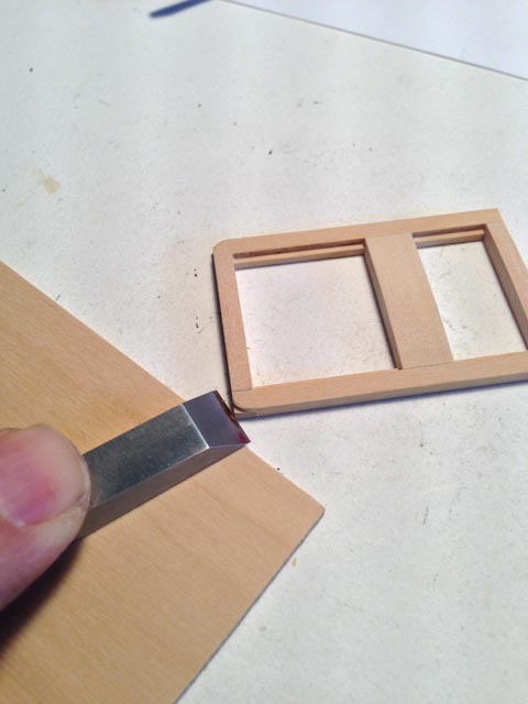
Hi everyone, Work has kept me from the shipyard; I wish it was the other way around... Here are the gratings and coamings completed. The Bellona has a very unusual serpentine curve to the upper side of the gratings and coamings. I made sanding blocks to accomplish this. The first photos show how I cut the template from thin plywood, then glued this to the end of a maple block. I then use a piloting bit on the router table to cut the profile all along the length of the block. I then rubber cemented sand paper to the surface, with some guide bars to keep the hatch/coaming in the center of the jig. I did the hatches and coaming separately, to get them down to size, and then I sanded them with the grating in the coaming frame so they would be exactly the same. The coaming ends are rounded, but only above the level of the deck planking. To arrange this, I used a blank of wood the thickness of the decking as a spacer to use my chisel to cut the coamings at the right height. A file rounded them off nicely. I used masking tape and scored lines to keep the black shoe polish off the square corners. When the decking comes in, it should be a very nice fit. I am showing a temporary jig for the main mast partners, to make sure everything fits and the mast rakes at the right angle, before constructing the partners. Best wishes, Mark


-
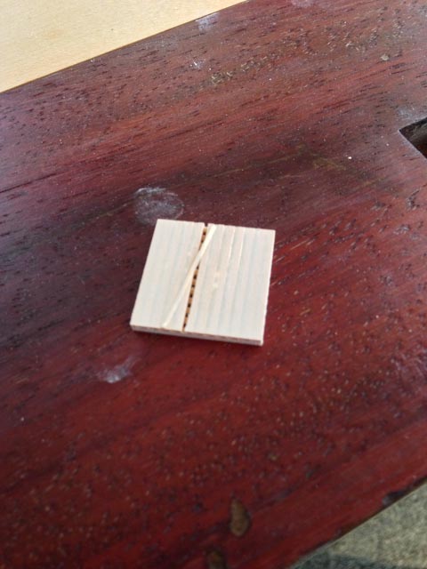
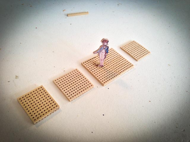
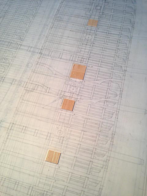
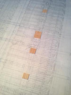
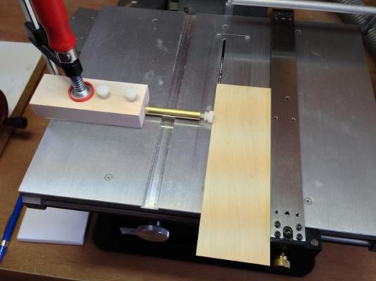
Hi, everyone, I finished making the gratings (sanding to profile yet to go...). The mill method worked fine, allowing me to make the gratings to exact size. Since the battens and ledges remain constant sizes in width, the only way to fit a specified opening exactly is to vary the spaces between in both directions. The mill allowed this kind of accuracy, and the gundeck drawing shows the new gratings fitting exactly. Sanding the bottom to reveal the spaces between ledges is fairly straightforward; I used sandpaper glued to plywood, to keep it all flat. The first photo shows what happens when the sanding gets close to finish--thin strips peel away. These are pretty accurately to size now, following Steel. My earlier ones were much out of scale; don't know how it happened, but ..... The last photo shows my new jig for repeatedly cutting thin strips (the battens, in this case) from the left side of the saw. Much safer and cleaner cuts. Many thanks to Michael Mott who helped me refine this idea. You can see the discussion in the Tools Forum, under micro jig. Best wishes, Mark


-
Danny, Fantastic work on the pumps. I had been wondering how to do the pump brakes, and you lay it all out in a very clear tutorial! Mark
-
micro table saw stop
SJSoane replied to michael mott's topic in Modeling tools and Workshop Equipment
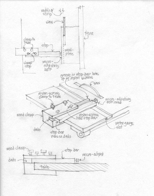
Hi Michael, Here is Mk1 of the jig. I didn't get around to making the specialized clamp around the table yet, and used a regular clamp temporarily to see how it would work. It is great. The micro-adjuster allowed me to sneak up on a perfect measure, and it was very fast and efficient to cut, move the fence and wood, cut again. It is safer, and the saw cuts more cleanly, making those small cuts on the left side of the sawblade rather than tight up against the fence. The nylon screw is gentle on the edge of the wood, and acts as a featherboard of sorts for holding the wood against the fence. My original drawing shows the clamp a little out of proportion to the actual table top. There is actually less overhang, and so less area for the clamp to grip. I am not sure how sturdy this original idea will be. I'll work on it another time... Thanks again for the elegant idea of the rod rather than the sliding wood stop. Mark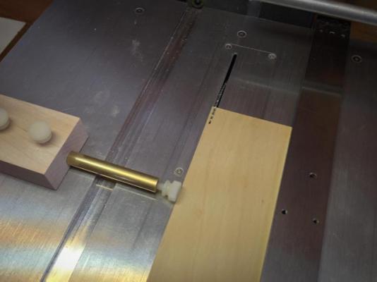


-
Hi Michael There is nothing like a shop reorganization for bringing more order into the world! Mark
-
Thanks, Remco, amazing. Mark
-
HMS Pandora 1779 in 3D
SJSoane replied to ppddry's topic in CAD and 3D Modelling/Drafting Plans with Software
I just came across your project. Beautiful work! I wonder if the individual parts could be sent to a three-D printer...! Mark -
Hi Remco, Can you show us how you did that? A scraper could not get into that tight corner. Mark
-
Hi druxey, On reading Antscherl in more detail, I drafted up the pumps based on the scanty information in the original admiralty drawings deck plan, and reconciled it with Antscherl's detailed reconstruction. I now believe that the circles I see in the deck plan may well be the rounded tops of the pump tubes seen within the cistern, not at the top of the deck where they have turned into octagons. I am going with the Antscherl reconstruction. Interestingly, the dimensions of the tubes on the 74 gun ship seem to be only an inch larger in diameter than the ones for the sloops. Mark
-
Thanks, Michael, I left a note at the tools and equipment posting. Mark
-
micro table saw stop
SJSoane replied to michael mott's topic in Modeling tools and Workshop Equipment
Nice, Michael! Much simpler and more elegant than my original sketch. I worried at first that the micro adjusting screw needs to be accessible even when the fence might be too close for a screwdriver to fit, and then I remembered that the fence can simply be moved away. Problem solved. I'll try building this next weekend; it will really come in handy for repeatable strips. Mark -
Hi Gary, This is a great way to go back and revisit details that were long covered up by later work. It is a great reminder of your excellent craftsmanship and attention to detail, including in the research! Mark
-
Karl, this is some of the best craftsmanship I have ever seen. Beautiful. Mark
- 662 replies
-
- 1
-
-
- bonhomme richard
- frigate
- (and 1 more)
-
Making gratings
SJSoane replied to marius's topic in Discussion for a Ship's Deck Furniture, Guns, boats and other Fittings
Greg, that is very ingenious. If I can't make my self-jigging idea work, I am building this jig for sure. Mark