


flyer
-
Posts
1,004 -
Joined
-
Last visited
Content Type
Profiles
Forums
Gallery
Events
Posts posted by flyer
-
-
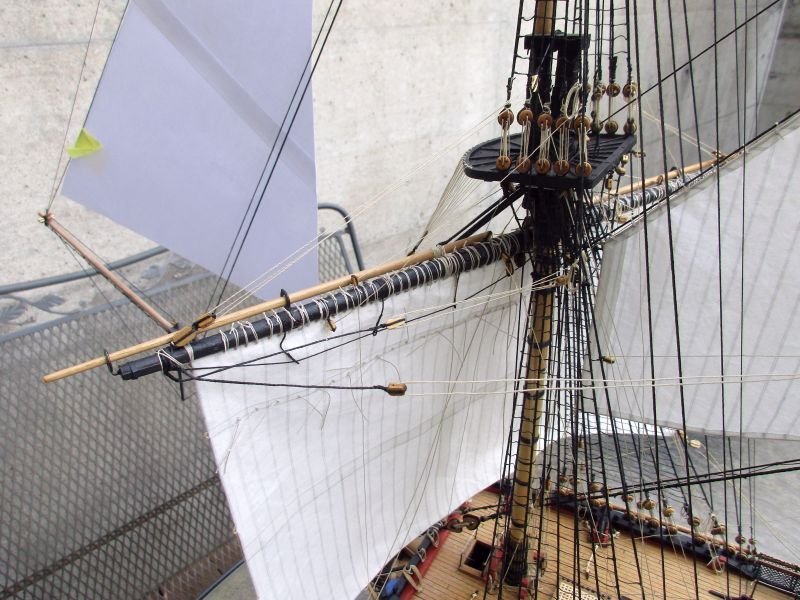
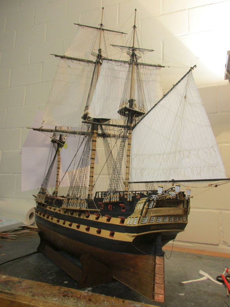
fore topsail
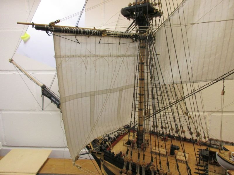
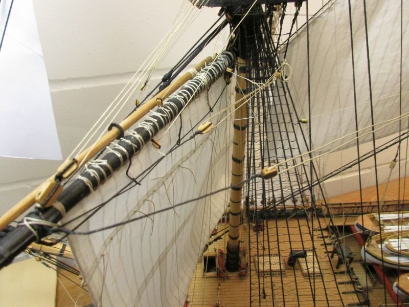
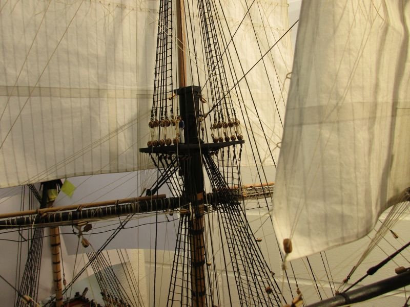
This sail was made and attached in a similar way as the previous two topsails. The space to work on the running rigging gets narrower and narrower as more sails are set. However I still think that the working sequence according to Wolfram zu Mondfeld's advice is sound: start low and aft and work upward and forward.
Some maintenance work is also continuously going on. Beside the dolphin striker I had to reset some too lose lines and replace a broken cleat. Like on the real ship - no rest for the poor carpenter and bosun.
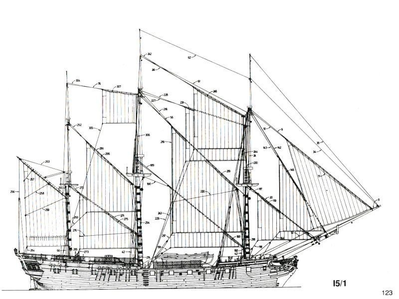
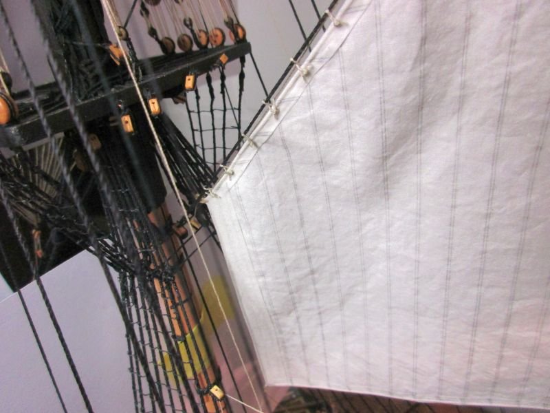
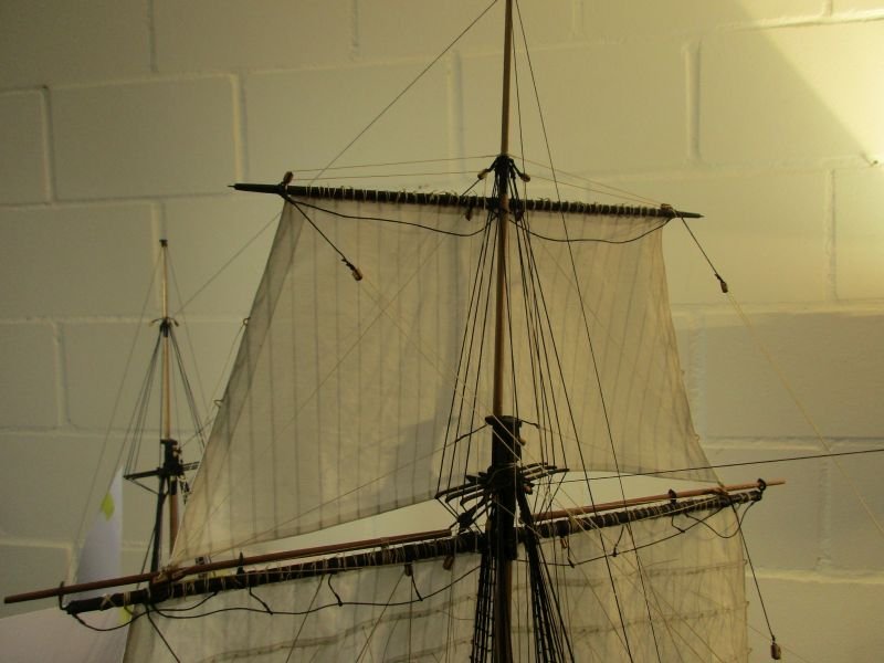
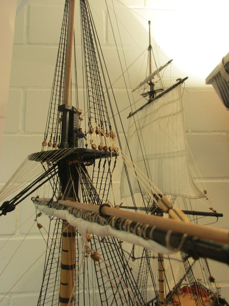
fore topsail set and drawing
those sails are pretty transparent
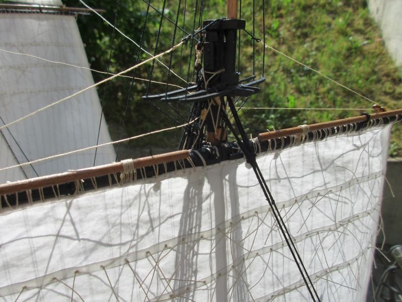
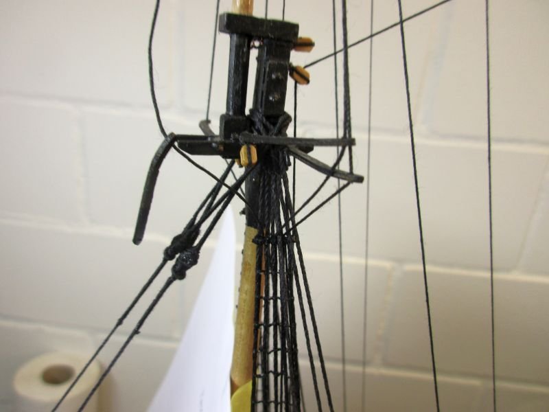
detail of the topmast head
-
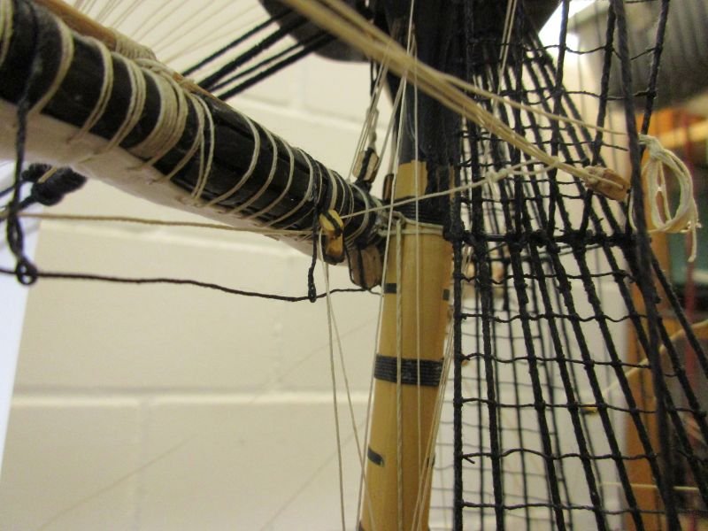
The dolphins strike back!
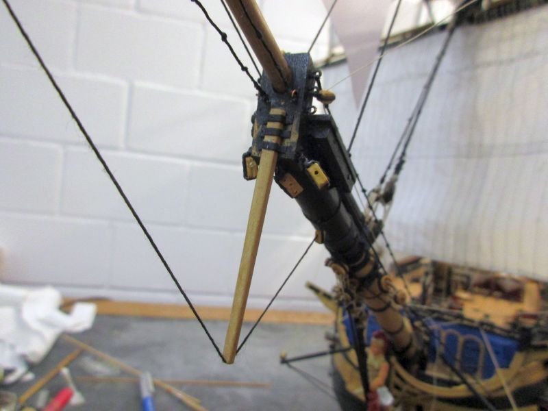
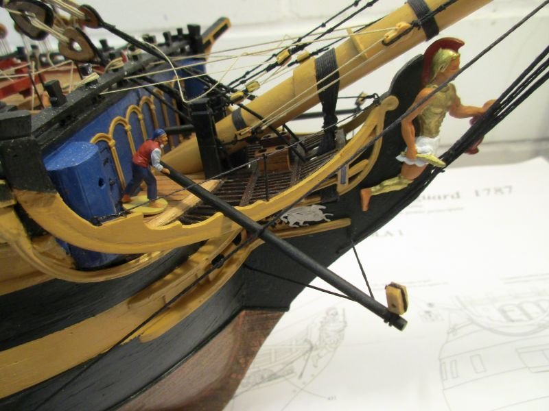
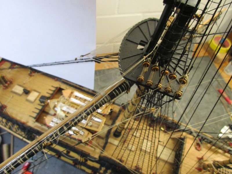
The dolphin striker broke 3 times (the original and twice a replacement made from the same plywood) and I started to wonder if this brittle part really did much good for the stability of the jib boom rigging.
I made a replacement from a sturdier piece of wood. A piece of 2x3 mm wood strip was worked to the rough form of the kit's dolphin striker, and 3 iron bands (cartridge paper) hold it against the bowsprit cap.
 the
the
raw dolphin striker with the 3 'iron' bands
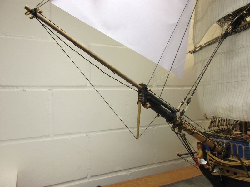
it is a bit fatter but not too much out of proportions
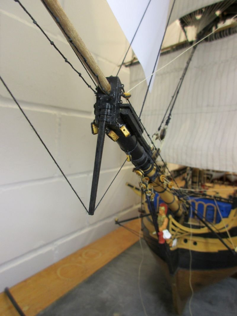
to quote Mick and Keith: paint it black
-
According to 'Seamanship in the age of sail' by John Harland the anchor cable never went directly to the capstan - except in small ships or boats - but was hauled in with the messenger. That messenger formed a closed loop around the capstan and a place forward, where the cable could be bent to it by the nippers (short bits of thin rope). The messenger was hauled aft by the capstan also taking the cable aft. When the cable neared a hatchway to the cable tier it was unbent and lead below. The messenger continued empty around the capstan and was lead back forward to be connected again with the cable.
When at anchor, the cable was tied off (belayed) to the riding bitts. Those are a substantial pair of square posts, projecting vertically above the deck and joined aft by a heavy crosspiece, just abaft the foremast. The unused length of cable went from there through the hatchway to the cable tier.
When the anchor was stowed during voyage the cables were unbent. In preparation for coming near land the cables were bent again and the anchor lashings removed except simple lashings to the ring and to the shank. In preparation for anchoring a sufficient length of cable for the expected depth could be ranged on the deck ready to let go while the part of the cable coming up the hatchway was already belayed to the riding bitts.
So... I guess you need to know in what situation your Mayflower is to know how to arrange anchors and cables.
And while writing this I realized that on my models I may have depicted some strange arrangements but then I'm only a landlubber, somewhat like-minded to Stephen Maturin.
Cheers
Peter
-
Many thanks for the positive feedbacks.
The yard tackles are very well documented in the kit's plans. You also find a description and an illustration on page 71 in Lees' The Masting and Rigging of English Ships of War 1625 - 1860, a treasure of information for working on our models.
Cheers
Peter
-
Fore course
While comparing the kit's plans and Lees' book I found that there seem to be too many buntlines in the kit's plans (also already installed for the main course). Lees mentions only 2 per side - a total of 4 - while the kit has 3 per side. The total of 4 is confirmed by several Books of the AOTS series. Therefore I reduced the number of buntline cringles at - and the number of associated buntline clothes on the fore course accordingly and could at the same time simplify the hole setup a tiny little bit. The 2 superfluous buntlines on the furled main course remain for now.
Making the sail, bending it to the yard and hoisting up the whole shooting match was similar to previously fabricated yards and sails.
The yard tackles were installed as on the main yard.
fore course with the 2 buntline cloths on the port side visible
the yard tackle is hooked into the futtock shrouds
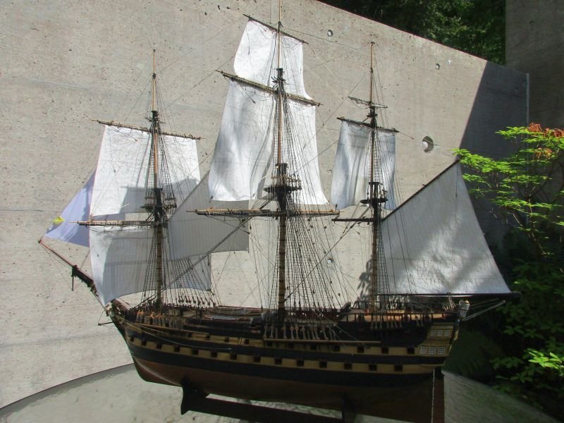
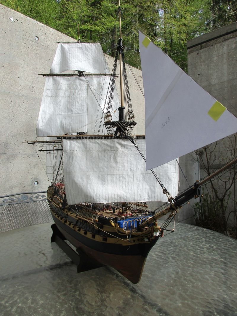
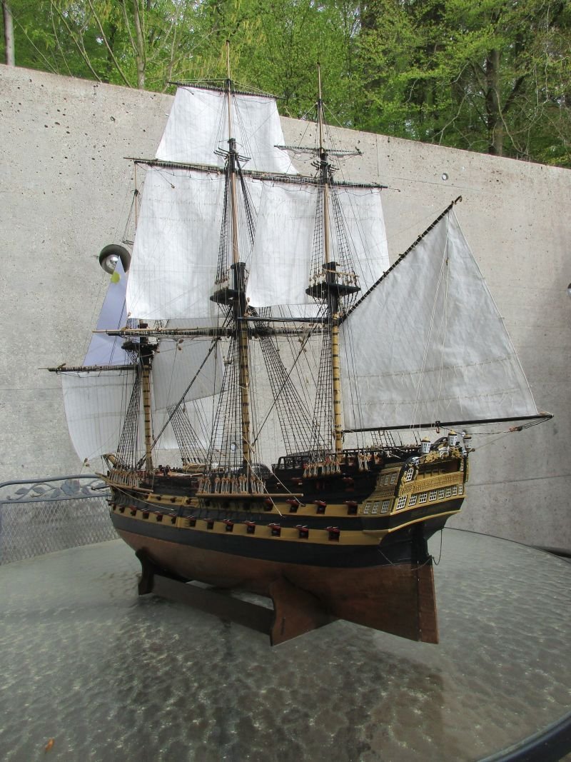
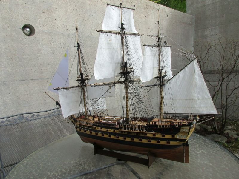
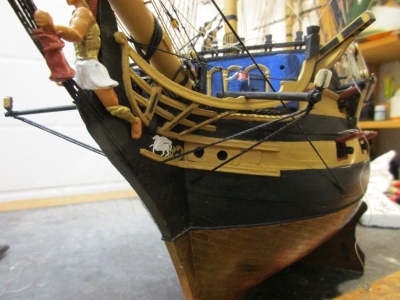
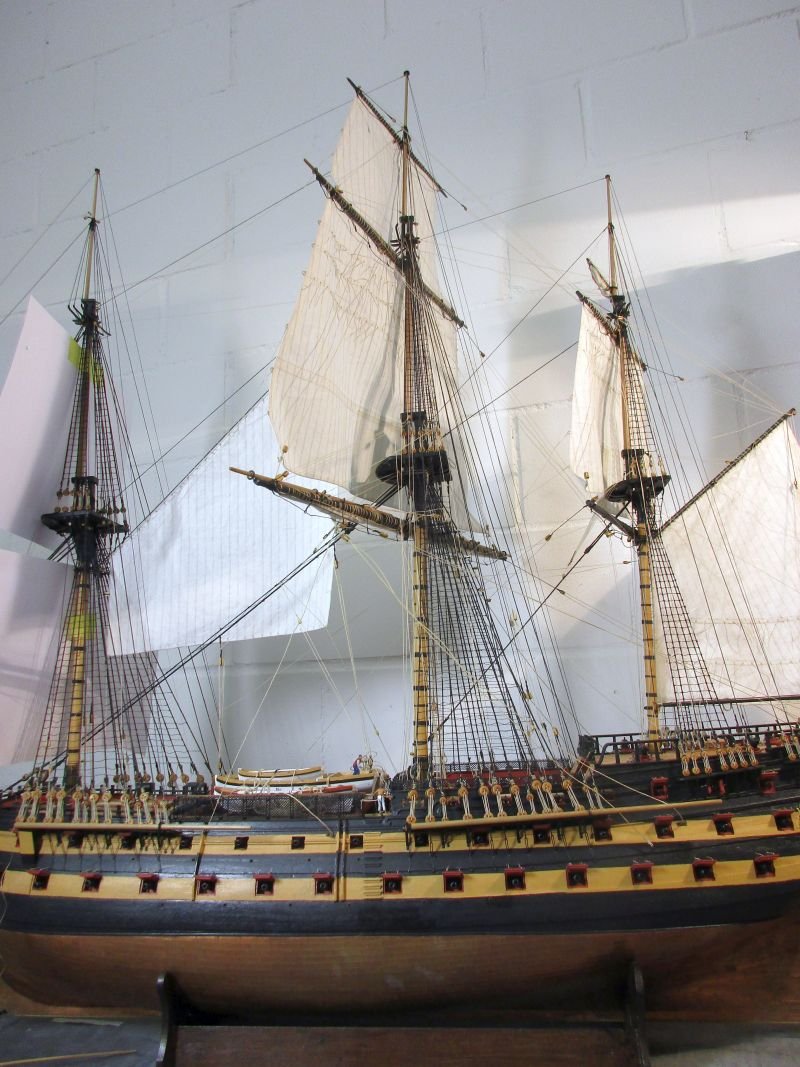
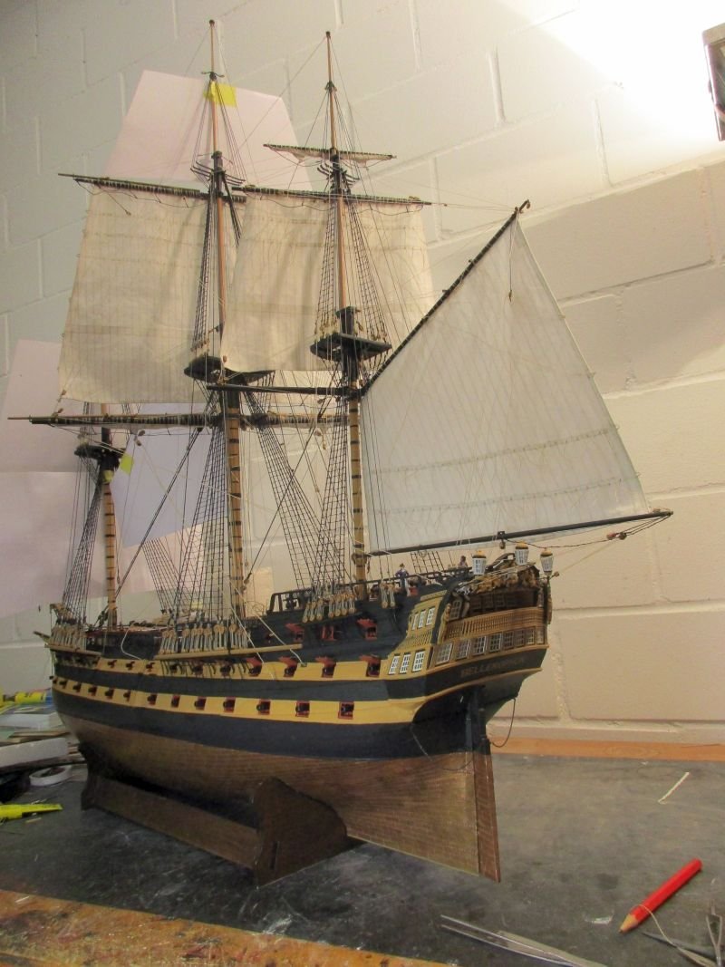
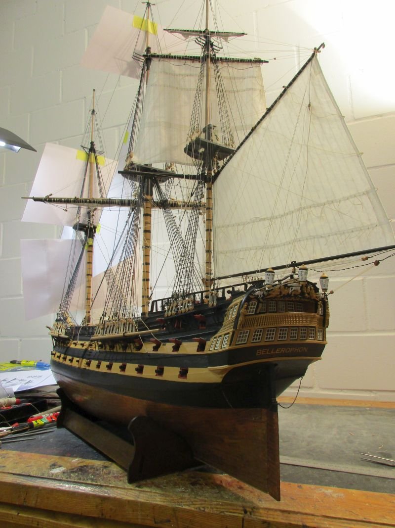
I also took advantage of the moderate weather (it was neither raining nor raining cats and dogs nor snowing although it is still the month of April) and took Bellona outside for a few photos:
-
This must be a record-breaking example of tin pest. The deadeyes are most probably pewter. To avoid tin pest it should be alloyed with antimony or bismuth. Given the amount of damage there seems to be almost pure tin - at least you shouldn't have a lot of toxic substances on your hands.
- mtaylor and Keith Black
-
 2
2
-
bumpkins
While working on the fore course I realized that the bumpkins were needed now. Installing as per plans was easy and the shrouds were such fun to set up that I did it twice. In the plans I found no information about their diameter. 1mm seemed logical as this was the same as the tacks. However, finished it looked out of proportion and I reduced to 0,75mm which looked better. The bumpkins are not lashed to the rail. Lees states that with the introduction of the 2nd shroud (ca 1773) the lashing was omitted.
1mm bumpkin shrouds - too fat!
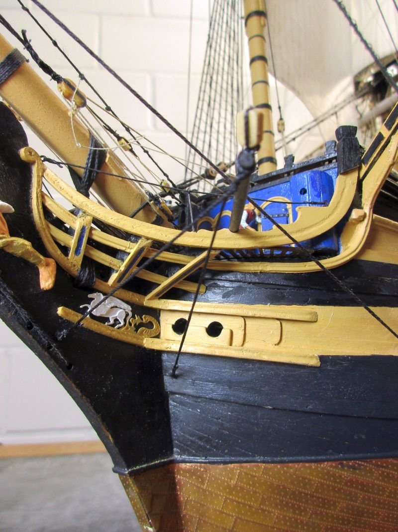
0,75mm - looking better
view from above
the bumpkins are not lashed to the rail
-
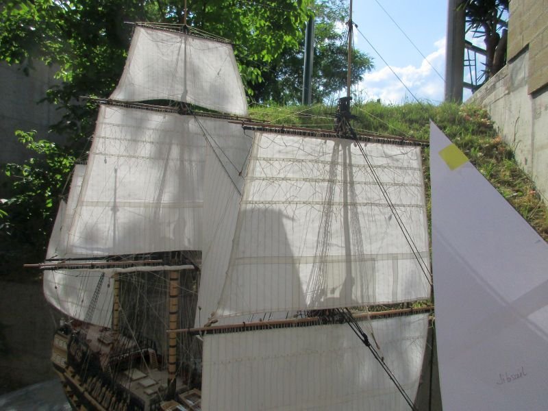
It seems to be the topmast staysail. In the book 'Pandora' (by John McKay and Ron Coleman) of the ATOS series you find that plan of all the staysails. The topmast staysail is the largest of them and if you check where its corners are in relation to the masts it fits the sail in the painting - which is by the way showing an extremely interesting manoeuvre.
Thanks for sharing.
Cheers
Peter
-
Hi Allen
Interesting information. Do you know how they stored the first shots for each gun when preparing for battle after they abolished the shot garlands?
And by BTW, if I'm not mistaken, the centre of buoyancy should not change if you move some weight lower down - just the centre of gravity should be lower and therefore stability should increase.
Cheers
Peter
- mtaylor, Aa-schipper, Roger Pellett and 1 other
-
4
-
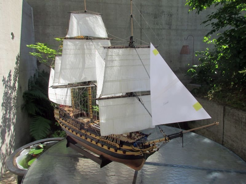
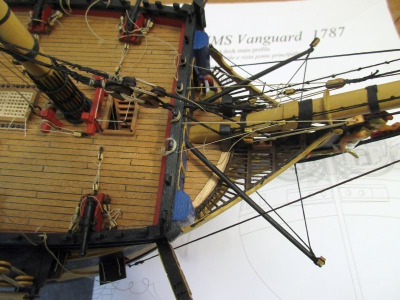
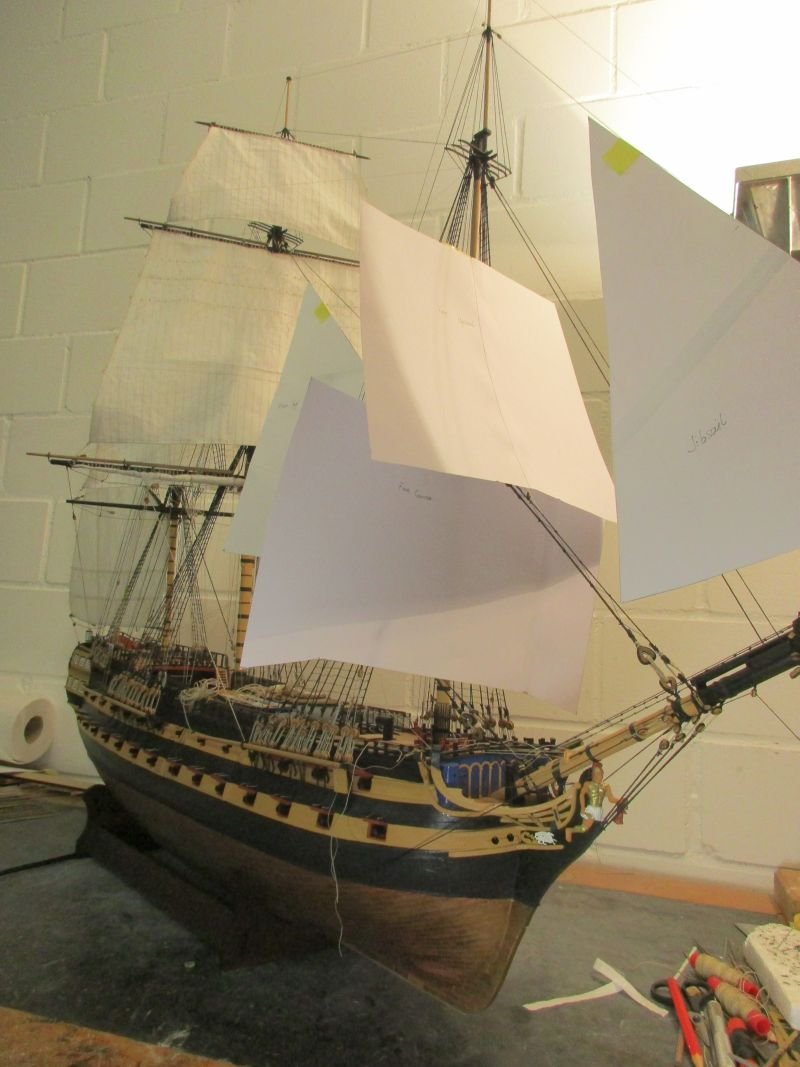
main topmast staysail
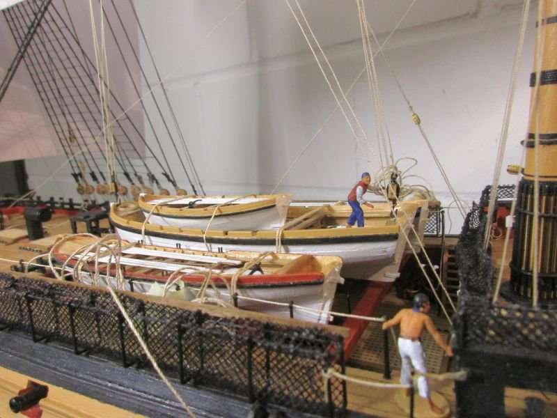
Before setting up that sail I installed the stay tackles. And after all those years I finally found the correct and logical position of them: One over the main hatch and the other over the fore hatch. When not in use both tackles should be fixed to eyebolts on deck. To better show the complete tackles I hooked them to two eyebolts in the launch - the same that would be used to lift that boat. My explanation is that that the boats are actually not covered and will be used soon. Therefore both tackles are already being prepared for the lowering of the boats.
Fortunately the sail itself is another rather simple one. It however potentially conflicts with the - yet to set up - braces of the fore- and the fore topsail yard. Therefore I attached most lines only provisionally.
Where to fix the whips (tackles) of the sheets needed thinking. The kit's instructions say to fix the standing part to an eyebolt 'on deck', while the running end is brought to the pin rail abeam the main mast. This looks strange, and would mean to fix a eyebolt near the pin rail which I dare say would cause quite a few stubbed toes.
Lees fixes one end to an eyebolt in the boat skid and the running part to the boat skid or a cleat close to the standing part. Boat skid? Perhaps this means the beams, where the boats are stored but that location is already a bit crowded. However this would be a different position, nearer to the centerline of the ship and probably a more logical position to operate the sheets.
As a compromise I bent both ends to the forward quarterdeck rail, as much to the side as possible.
Some time I pondered about how to bend the sail to the stay: Rings, hanks and robands in different forms are methods shown in my clever books. Finally I used robands in a figure of eight form as implied but not specified in Lees.
tackles and staysail added
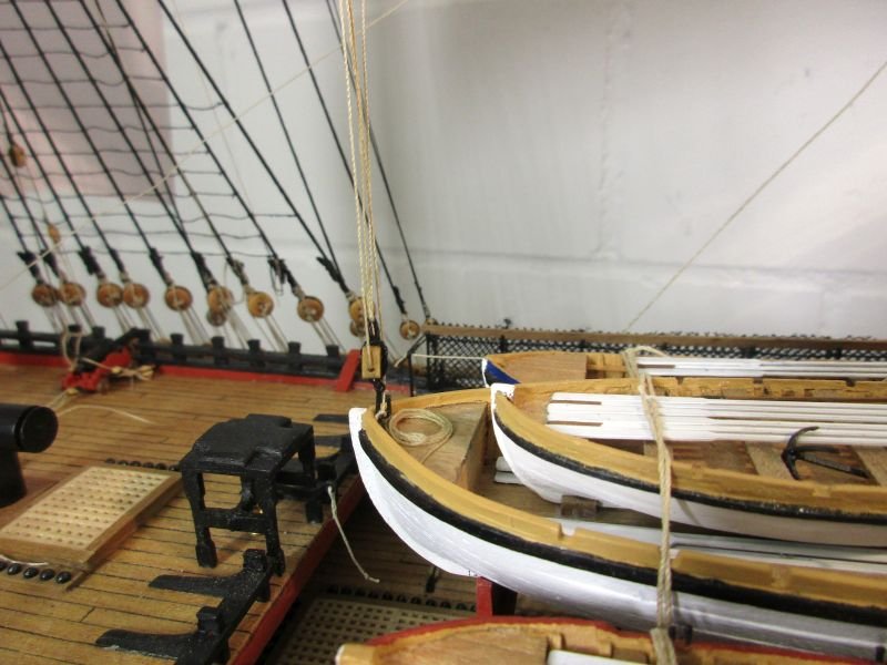
fore hatch stay tackle fixed to the launch
main stay tackle
staysail with robands
where the port side sheet pendants are belayed
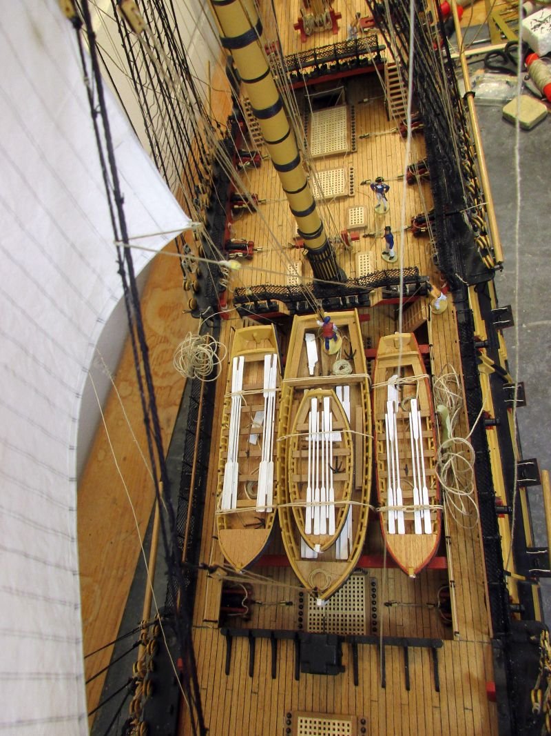
overview of the deck with port staysail sheet
in the meantime the carpenter also found time to fix all the gun port lids
-
Hi Malcolm
Your Agamemnon is looking goood!
Might I suggest to install some dummy gun carriages for the dummy guns on the lower deck - perhaps something like I did on Bellerophon (which I copied from md 1400cs' Wasa)?
Sure, it's tedious work, but I think it very much improves those fake guns.
Cheerio
Peter
-
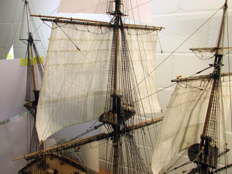
main topgallant yard and sail
This was supposed to be the easiest sail to set so far: No reef bands and only simple leech linings.
Well, I wasn't right.
The sail itself was rather quickly done and bent to the yard. But then I realized that the same amount of running rigging as for the other sails had to be set up and threaded to the maze of already installed lines. And having the yards braced made access from the starboard side more difficult. Sometimes I could work across the ship which however endangers what's already there. But the whole workforce finished the task accident-free, for once.
In one point I had to deviate from the kit's instructions. As confirmed by Lees, the buntlines should lead forward, through a sheave in the fore topmast aft trestletrees and down to the deck. I forgot to drill the necessary holes when setting up that top. After the near disaster with the crosstrees I didn't want to drill 0,5mm holes into a 1mm wide, flimsy plywood part. Fortunately Lees sais that earlier there were blocks lashed to the same trestletrees to carry the buntlines. A worried skipper and an old fashioned bosun then decided between themselves to set up the buntlines the old way.
Now, half of the sails are set and I'm quite positive that I shall indeed finish Bellerophon in this decade.
main topgallant sail set
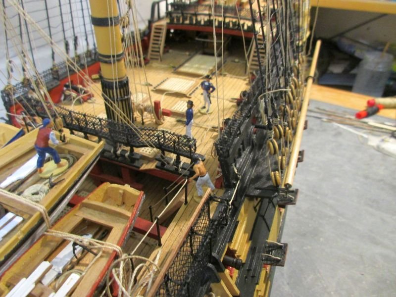
main top with belayed topgallant sheets
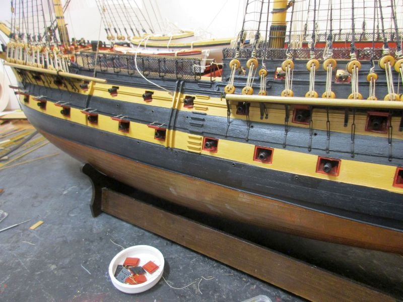
the carpenter is also installing the missing lids to the portside gun ports
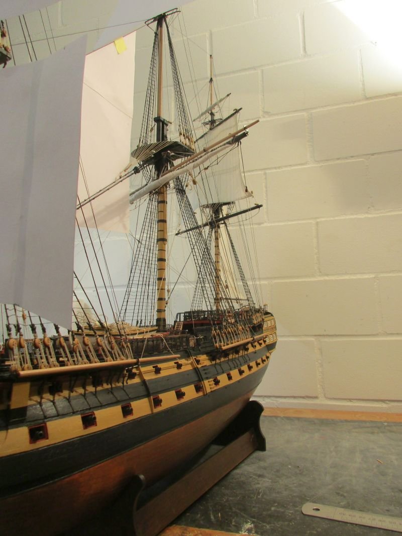
taking total view shots is becoming more difficult - Bellerophon is definitely outgrowing my work space
- egkb, mort stoll, Spaceman and 9 others
-
12
-
Hi Tom
Many modellers unfortunately use too bright colours. Using them straight out of the bottle or can lessens the look of their model. I highly recommend to dull all so called 'original' paints. Allow me to repeat something I wrote in my Bellerophon log some time ago:
(In a book, written by a professional model railroad landscape builder he explains about colour scale. By that he means that if you look at a model in scale 1/100 from a distance of 50cm it should look the same as the prototype from a distance of 50m. And from that distance colours look less bright because of the air absorbing some of the intensity. He says that's the reason that models tend to look like toys if you use original colours. He recommends to always mix in a bit of white or grey and to avoid shiny colours. I think it works.)
Usually I mix about 15 % dull white into any color I use, including black.
Regards
Peter
- Keith Black, mtaylor and CiscoH
-
2
-
 1
1
-
main topsail yard and sail
Sail making and -hoisting slowly became not exactly fun, but an acceptable routine. Or so I thought, until I spotted 2 broken crosstrees on the fore mast. Turning the model to get access to both sides is tricky but necessarily quite often done. It must unobserved had happened during such a maneuver. This was not the first similar accident and I find that many - especially newer kits - have rather flimsy crosstrees, likely to break. I wonder if it wouldn't be more sensible to provide them as an photo etched metal part.
Anyway, I carefully drilled 0,5 mm holes lengthwise into the broken parts and the trestletrees , inserted very stiff 0,4mm copper wire as internal splints and glued with epoxy. So far it holds.
The main topsail probably is the largest and most complicated sail but routine helped in making it. Putting it up according to the kit's instructions went fine.
I rather like the look of those sails and of my Bellerophon.
result of an unwatched accident

after some plastic surgery
finished sail ready for the yard
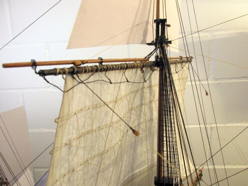
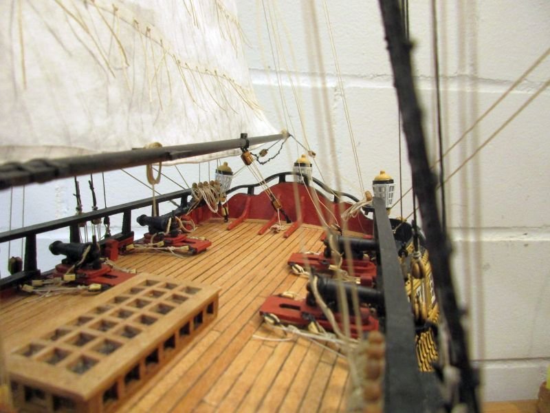
views of the main top sail
the main bitts look properly crowded
sailing slowly away...
- Prowler901, mort stoll, Mr Whippy and 6 others
-
9
-
While I see many excellent examples of sails in this discussion I would suggest also to give some thoughts to how to set them:
Perhaps I'm a bit fussy - especially for a landlubber - but after all that work we put into building a perfect model I find it a pity to see it set up in an altogether unrealistic stance.
In my opinion it's best to imagine the model in a concrete situation to avoid an unrealistic setup: What amount of wind is there and from what direction does it blow? As the best point of sailing for most square riggers would be with a wind from an aft quarter you would see her most of the time sailing with braced yards and only a selected amount of sails set. A squarerigger with exactly squared yards and all sails set and filled with wind from dead astern therefore looks a bit unrealistic as the aft sails would partly or fully becalm those on the main and fore mast. Only mizzen sails and some on the mainmast would draw. Also filled square sails set on exactly squared yards plus equally filled fore and aft sails set along the centerline seem a contradiction. And with sails fully filled, the ship would hardly lay on an even keel.
On the other hand if you think about some light winds you could set as many sails as you like. Just keep in mind that with fore and aft sails set the yards again most probably would be braced. All sails set and all yards braced square could only mean that you are taking advantage of the present calm to dry all your 'laundry'. Which then should hang limp.
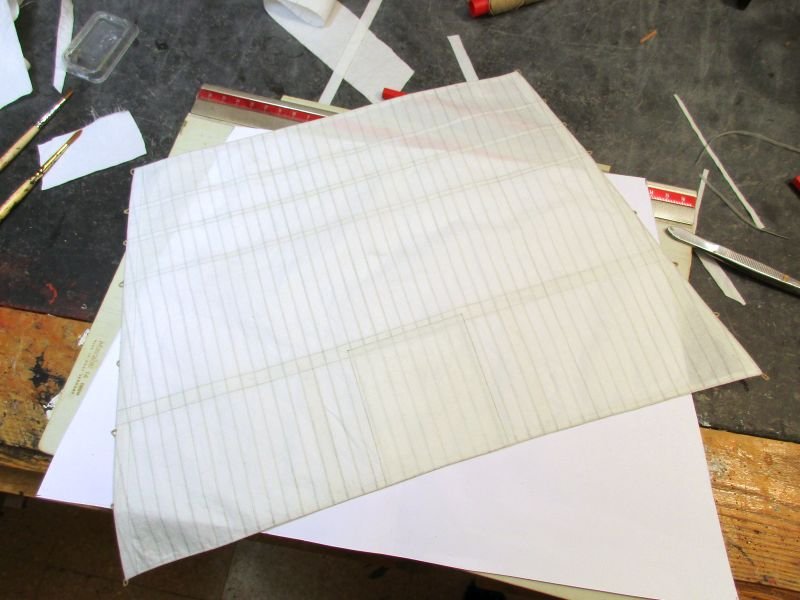
For my sails I prefer a very, very light cotton with penciled on cloth's seams and glued hems, reef bands and linings. The bolt rope is glued into the hem and - in my opinion - looks even better than one attached with almost unavoidable oversized stitching. I use a special textile glue. This method is the result of several articles found here on MSW.
Some silkspan sails do look terrific (e.g. those B.E. made) but others still seem a bit papery and I guess handling of that stuff isn't as easy as handling some good old-fashioned cotton.
But however the sails look like - I'm a great fan of any sails on a model ship. The simply perfect the picture.
Cheers
Peter
- robert952, mtaylor, GrandpaPhil and 1 other
-
4
-
On 12/23/2022 at 12:54 PM, Ian B said:
Hi I'm now doing my spanker...going to do it the same as you..yours look fab ..I hope mine turns out just as 👍👍👍
Hi Ian
Thanks, but there is more than one reason to lower the image definition before posting the pictures...
I'm looking forward to see your spanker - in high definition.
Cheers
Peter
-
On 12/23/2022 at 8:26 AM, Blue Ensign said:
Great set of photos Peter, she does look impressive.
B.E.
Hi BE
Thanks a lot.
I'm using a rather old Cannon Ixus. The colours and brightness sometimes need reworking but the camera's lenses are still superior to anything smartphones offer.
Cheers
Peter
-
I always liked the look of OCCRE's Diana - except for the fact, that looking from behind she seems to lose her trousers.
As Mark said, you would have to remodel the complete stern as well.
Perhaps you would consider to build Amati's Fly? She cost just a few pounds more, builds to a model of about the same dimensions, has three masts as well, is in a more convenient scale and is much better researched.
Regards
Peter
-
Meriadoc and Alan,
Yes, landlubber me was confusing some nautical terms - once again I feel a certain kinship with Stephen Maturin.
Meriadoc, what I meant was sling. The log is now corrected.
Alan, you are right, of course, about the tie. On Bellerophon however I think I installed jeers. As I understand James Lees they complemented and finally replaced the ties in the 17th century.
Thank you very much and Happy Holidays!
Peter
-
-
main yard and course
The main course's area was also reduced by about 30% and the simplified sail then bent to the yard. (Easily said - but I had to knot about 90 robands.) Buntlines, bowlines and clue lines were added and the sail then furled. It sits perhaps not high enough on the forward side of the yard, but I didn't want to cover the studding sail booms.
Setting up the yard was started with the sling. Then again followed a process of balancing lifts, braces, jeers and trusses to get a horizontal yard, braced by about 20° and with no slack in the sling. How to set up lifts caused a bit of head scratching: With yards squared it is obvious how to lead them in order not to conflict the standing rigging. But with the yard braced you will have to set them up the same way and they will not run free anymore but bend around the standing rigging. And of course the yard itself presses onto the foremost shroud on lee side. Letting loose the truss falls a bit helps here.
Then I had to lead all the lines through the correct blocks to the appropriate belaying points. Some I had to improvise, such as those for the yard tackles and its gear.
For the buntlines I changed the run under the main top. I had installed additional blocks and each runs now through two blocks in succession, similar to the plans for the fore course buntlines, and so clear the yard.
Now I only had to fix and coil a zillion rope ends and voila - another tiny step towards completion was done.
Sometime during that step, when I had enough of lace making, I finished the stern lanterns.
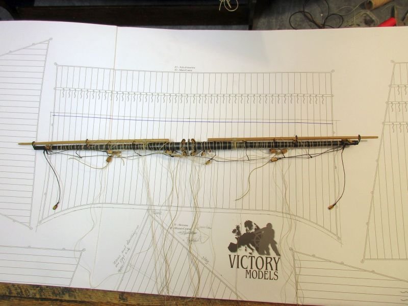
main yard from above - the reduced sail area is marked in the plan below it
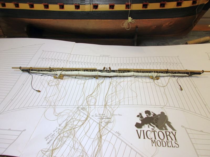
yard seen from below
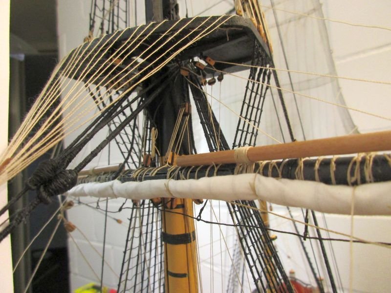
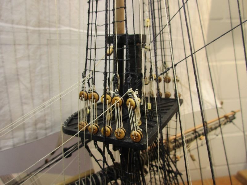
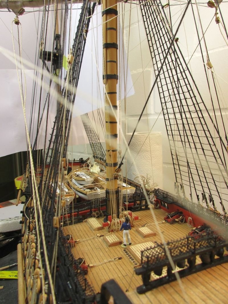
sling, jeers and lifts as well as buntlines visible below the maintop
detail with truss
main yard from above - kink in lift due to the foremost shroud visible
Do you see the sailor in the maintop? Those ships were huge!
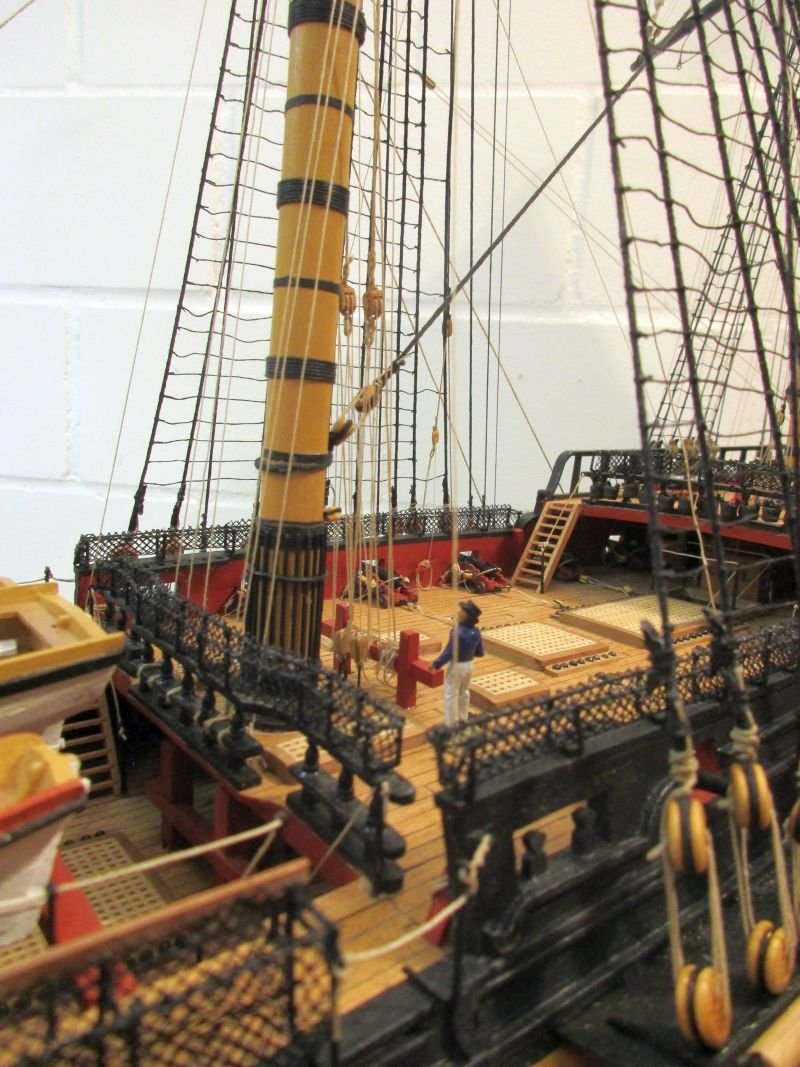
foot of the main mast with bitts quite full
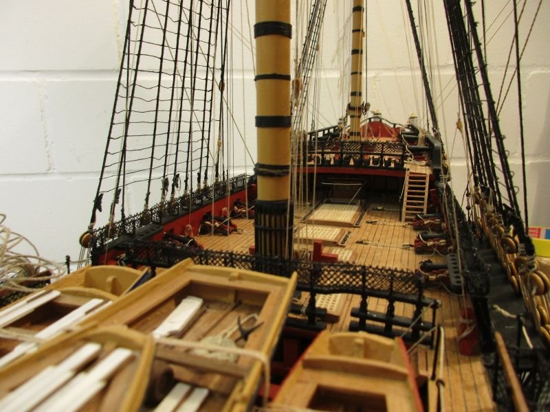
view along the deck
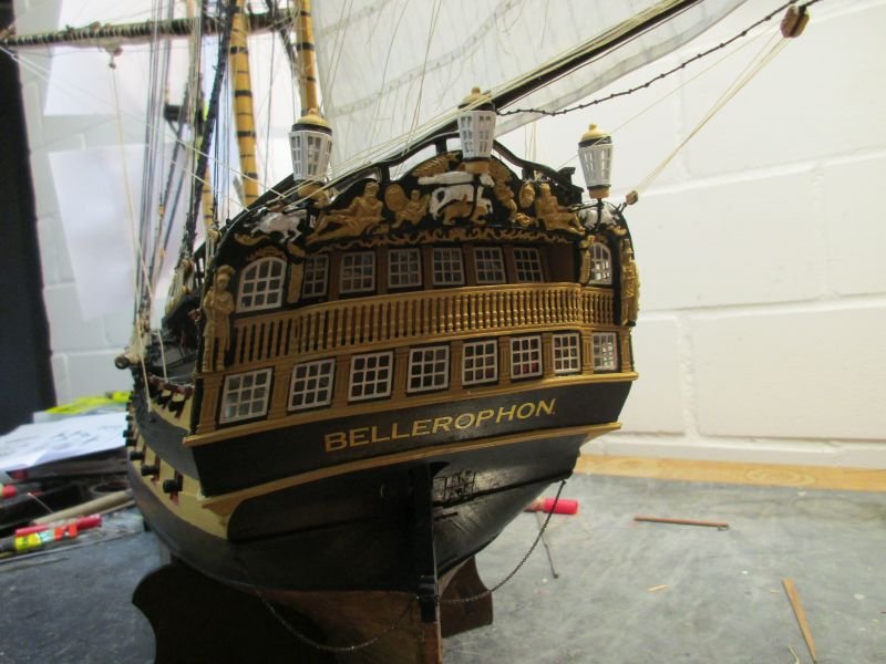
stern lanterns in place
she's taking shape
-
-
Hi Nils
Just found your album of the pilot schooner. Again an outstanding build! (But who would expect less?) I really like that every one of your beautiful models clearly bears your trademark, setting them apart from the rest.
Cheers
Peter
-
Hi Alan
You are on a most interesting journey - thanks for taking us along. Watching you struggle with the correct form of those stern timbers lets me appreciate how complicated the work of those shipwrights really was. I guess they had to try, correct, try again and correct again their timbers as well. But in scale 1/1 that was some heavy load to shift each time. On the other hand they could make corrections with the timber in place - where you have not enough room to work.
It's a pleasure to watch your Bellerophon taking form.
Peter

Chris Watton and Vanguard Models news and updates Volume 2
in Traders, Dealers, Buying or Selling anything? - Discuss New Products and Ship Model Goodies here as well!!
Posted
Bristol seems a very interesting choice. Just a question:
Would it perhaps be possible to construct at the same time an additional 'difference-kit' which would allow us to build that other famous ship of the Portland-Class: 'The horrible old Leopard' of Patrick O'Brian/Jack Aubrey?