


flyer
-
Posts
1,004 -
Joined
-
Last visited
Content Type
Profiles
Forums
Gallery
Events
Posts posted by flyer
-
-
Hi Bug
Your Pegasus is coming along real fine. I especially admire the extra details you add - and their quality. (I'm a fan of including the scuppers too, but I never had the guts to drill them through from the inside - I just show the outer opening.)
However I hope you permit a remark to your gratings. As far as I understand the gratings were removable while their frames were fixed to the deck. For stability therefore the removable lighter coloured insets should end on a frame and not on stubbles. You could check on the example in this article:
Sorry for nagging but to me this detail sticks out like a sore thumb.
Keep up the great work.
Cheers
Peter
-
Hi Alan
Yes, diameter. Perhaps an accidental slip into a too verbatim translation. In German technical texts you use sometimes 'Stärke' as diameter.
Be aware that I don't check all rigging diameters against the tables in Lees - only when I see some strange proportions or if it seems illogical from a technical point of view I do a crosscheck.
According to Lees the futtock shrouds should have the same diameter as the corresponding topmast shrouds - which is logical. They have to transfer the pull from the topmast shrouds to the anchoring point on the lower shrouds.
Peter
-
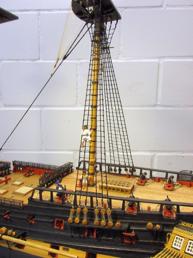
Main mast
The lower main shrouds were set up in a similar manner as those of the mizzen. The futtock shrouds have a strength of 1 mm.
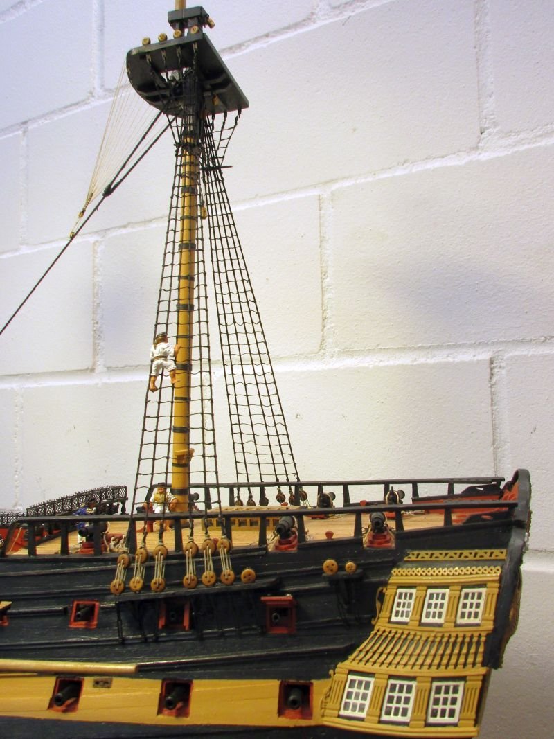
Some alterations to the main stay and its preventer stay were necessary. The kit's plans are a bit ambiguous as how to fix the forward ends to the bow. After some searching in web and books, I decided to follow Lees and set the collar of the main stay up the way the preventer stay is shown on the plans: It leads below the forecastle rails and the collar goes through the hole in the beak below the bowsprit. The preventer stay leads over the rail, it's collar over a pair of new stop cleats on the bowsprit and through an additional hole in the beak. It runs a bit close to the seats of ease and may irritate the seamen there but nobody said that the life of a seaman is a bed of roses.
The snaking of both stays was continued past the foremast. On the plan it ends there but probably this is because the preventer stay up to 1793 only went to the foremast and only later to the bowsprit. As I try to show my Bellerophon the way Napoleon might have seen her, I set the preventer stay up in the later fashion.
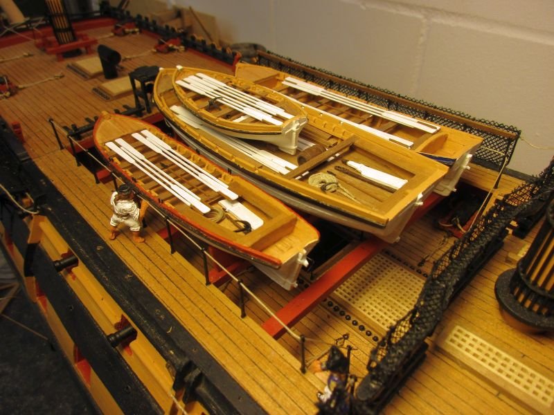
The lashing of the stowed boats seemed inadequate. I cut the spliced eyes from the ringbolts and threaded the lines through it and set them up double. That will look better in some lively weather.
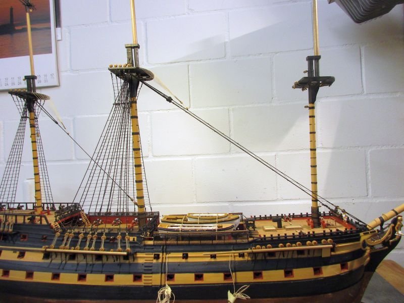
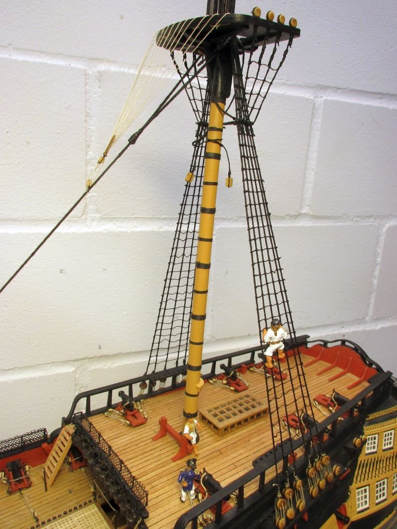
Main shrouds and stays
mast top with crowsfeet
stays on the starboard side of the foremast
stay collars

better lashed boats
- Martin W, BenD, GrandpaPhil and 4 others
-
 7
7
-
Hi Walrus
Pickle is my favourite build. But I never really liked the look of the 'out of the box' builds. The sources of the kit's planes seemed doubtful to me and I took an RMG plan of an Adonis class schooner as main reference. The result still pleases me very much and has a prominent place in my house.
Regards
Peter
-
Hi Robert
Your Victory really is an outstanding model. Comparing my Bellerophon with your build I can hardly believe that they are in the same scale. Being at exactly the same stage as you I will visit your log occasionally and hope to shamelessly profit by your example.
I Love the quality of your pictures as well.
Regards
Peter
-
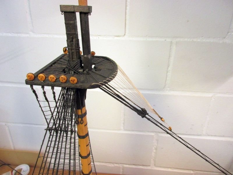
Standing rigging
Mizzen mast
Again I started low and aft at the mizzen mast with the standing rigging.
First I prepared the tackles and shrouds around the masthead. Then, after putting up the first three shroud pairs, I installed the respective stay and tried to balance the forces on those lines, while keeping the mast upright. Several deadeyes had to be reset to get an more or less even distance from the deadeyes on the channels. Then the remaining shrouds were set up. First priority always has an equal pull on all the shrouds and the deadeyes forming nice parallel lines only second. In fact I think that on real ships all those ropes constantly worked and resetting of the shroud lanyards probably was an constant process, keeping an even pull on all that shrouds during hot, cold, dry and humid weather. I doubt that every time the deadeyes were newly aligned as well. At least this is my excuse for the uneven line of my deadeyes.
To set up the ratlines (yay!) I used cow hitches at the ends and clove hitches between.
Finally the crowfoot was set up.
A first few corrections to the strength of some lines in the plans were necessary:
- the strength of the futtock shrouds on all masts is of course the same as that of the associated topmast shrouds.
- the catharpins in the plans are to fat. According to Lees they should be 25% of the main shrouds which are 1,3mm - I took 0,25mm line for the catharpins.
one seaman to set up the ratlines and two to supervise him - efficient would be different...
-
The spritsail yard was made with some changes to the kits plan. The centre part is only 8- instead of 16-sided. in Lees I found no information which showed it 16-sided - the crossjack seems to be the only one with this feature.
Also the holes in the yardarm of the spritsail yard - supposed to take the sprit topsail sheet - were replaced by blocks at the yardarms. Lees doesn't mention any sheaves in those yards but leads the sheet through blocks.
The boomkins were also made but only provisionally fixed. Putting them in too early would be just another disaster waiting to happen. They are a bit sturdier than the kits sketch. Again I tried to follow Lees.
While working on this I thought about how to fix the boats on the beams. As I know Murphy, he would like to have all kind of things falling into to waist, out of reach as soon as the boats were fixed. So the lashing of the boats will have to be easily releasable. The first solution was to splice a line to an eyebolt on one side and the lead the line alternately over a boat and trough an eyebolt on the beam until fixing it to the eyebolt on the other side.
While working on the rigging I may come up with a better solution. I think the boats were lashed individually and I should try to imitate this better.
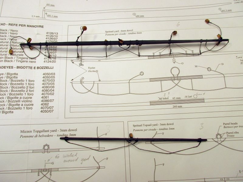
Spritsail yard and sprit topsail yard
boomkins
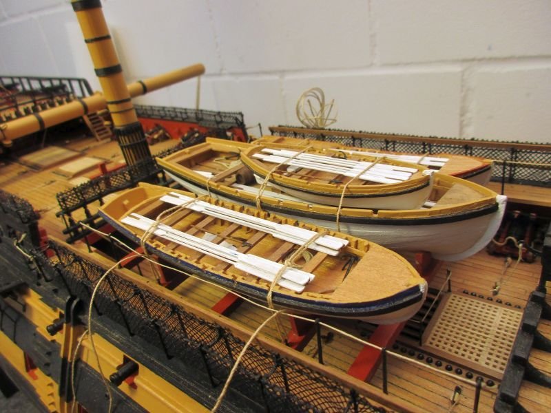
boats lashed on the beams
false splice
Somewhere in those pages I found a 'false splice' which I would like to share here. I use it often, find it helpful and it's easily done. The example is the lashing line for the boats, spliced to the first eye bolt.
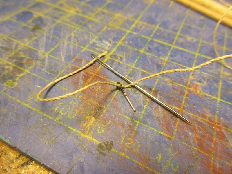
1: thread the line through itself
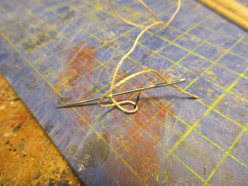
2: ...and back again, marking the length of the splice.
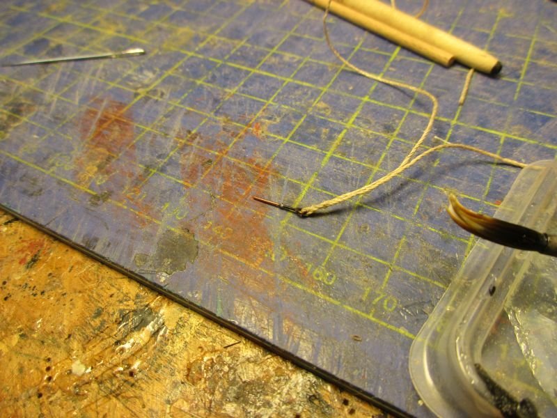
3. pull taught and fix with diluted glue
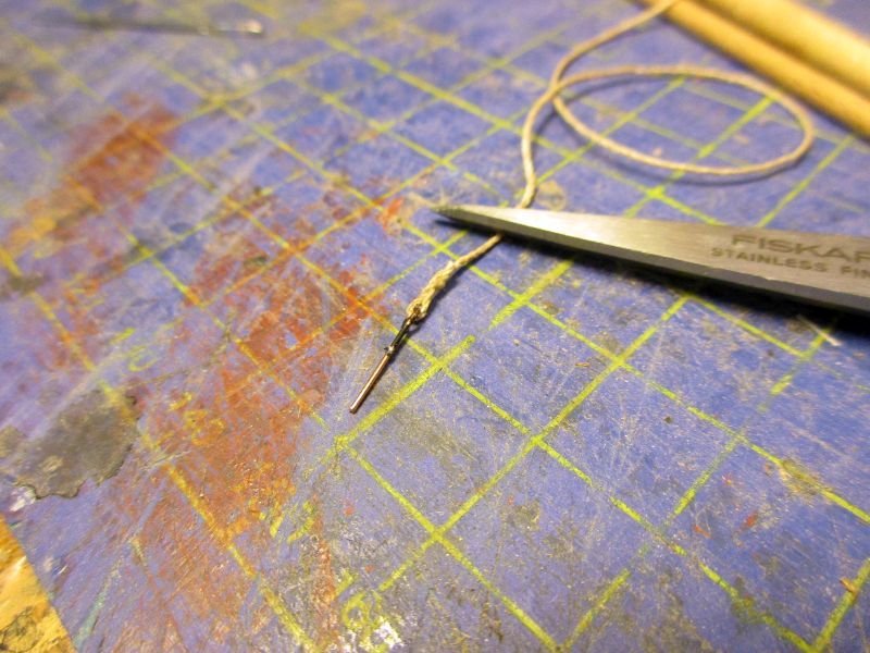
4. cut the free end to length. Voila!
-
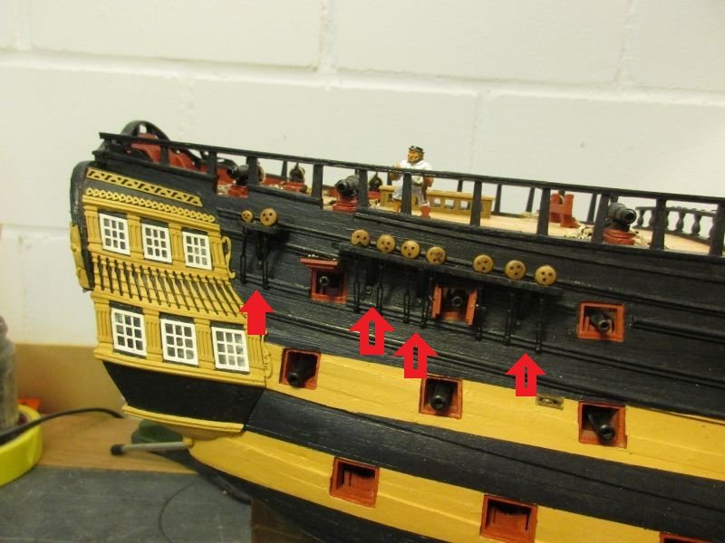
Rudder improvement
AON showed in his wonderful Bellerophon build, how to improve the look of pintles and gudgeons on the rudder. They are etched brass with a row of holes. Using those holes to nail the parts on would have given a too coarse impression. I just glued all on and left the holes open. Now using a drop of glue, applied twice into the hole and painted black or copper simulates an acceptable bolt head.
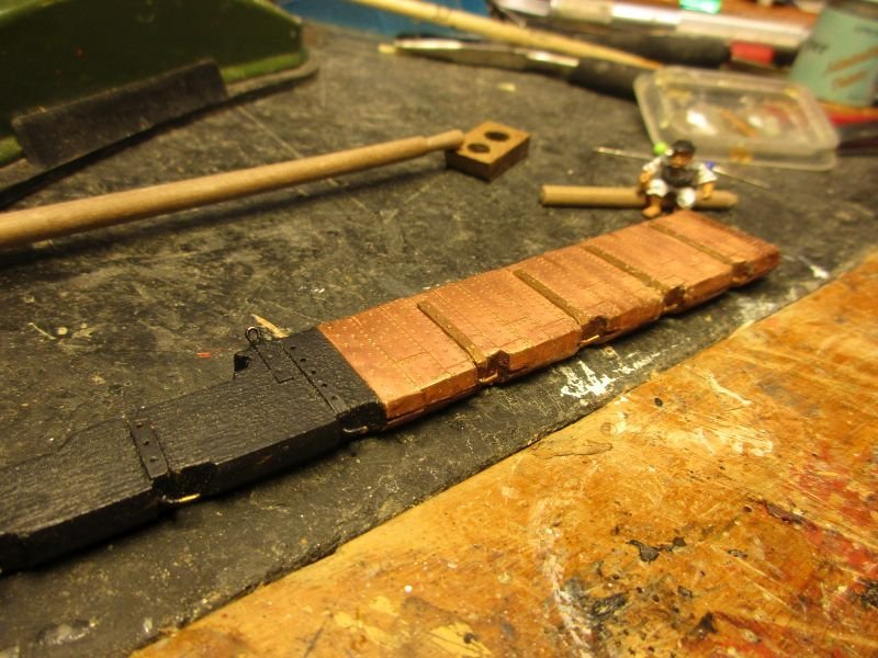
the rudder before reworking with holes instead of bolts
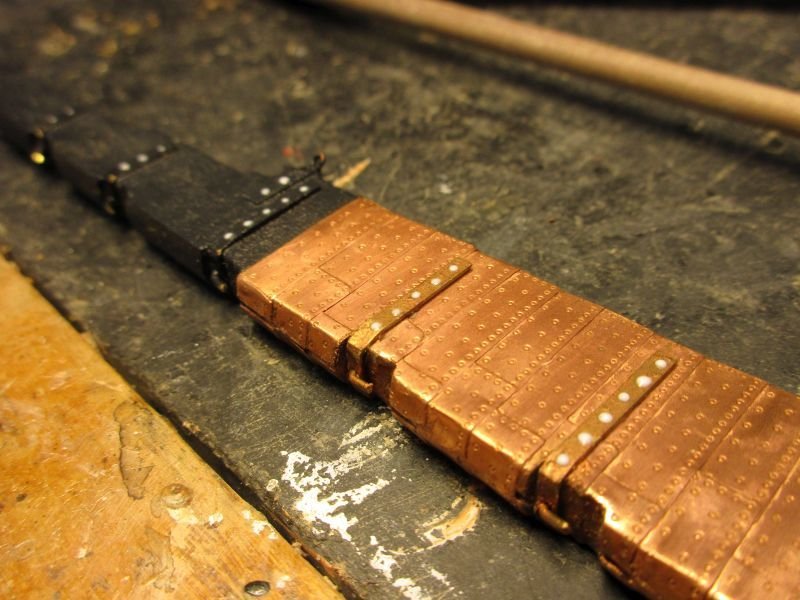
glue drops applied
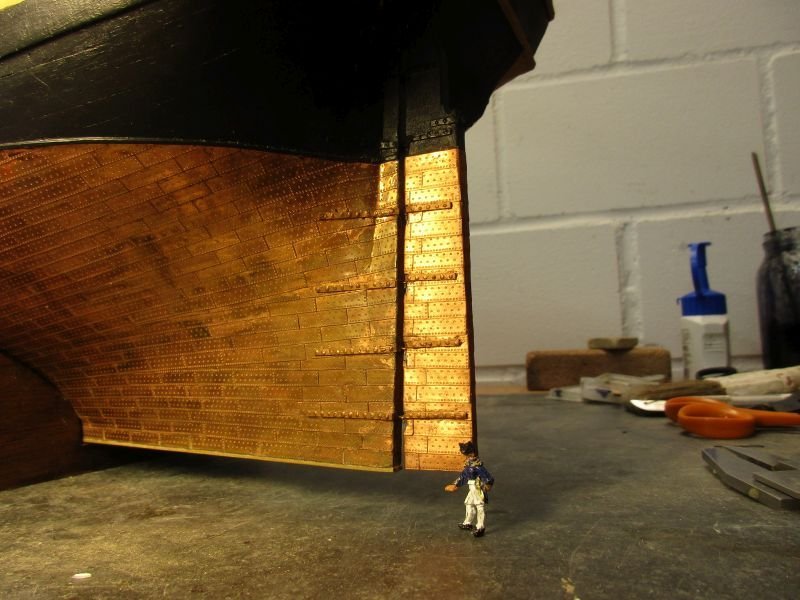
reworked rudder hanged again
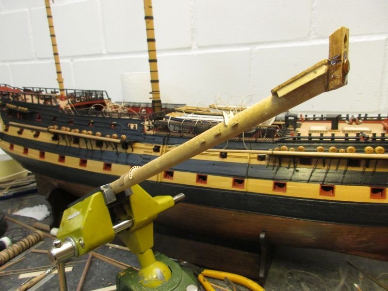
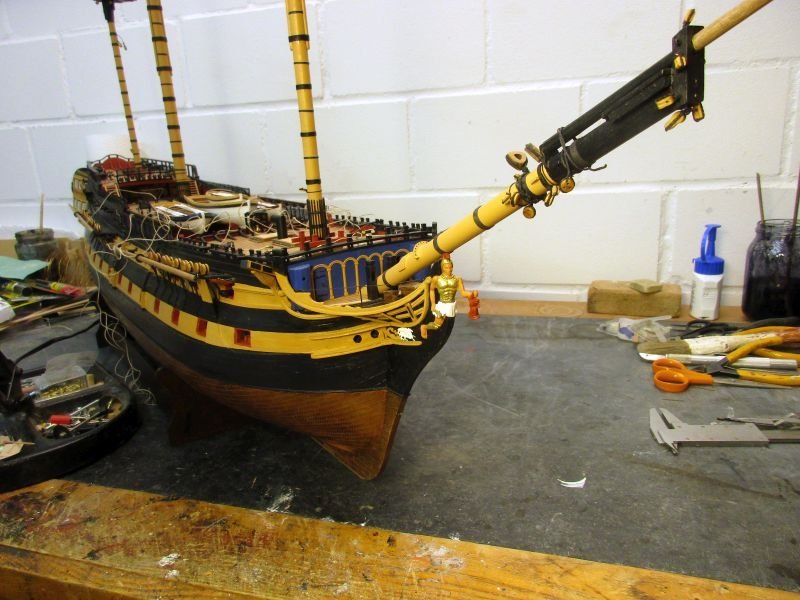
Bowsprit and jib boom
The bowsprit was quite an interesting spar to build. To facilitate the adjustments according to the angle of bowsprit, I set my vice to the same angle for most of the construction.
While handling the jib boom I decided not to fix neither jib boom nor the dolphin striker yet (more to that part later) but wait until the rigging process would need it. This will reduce the risk of damage especially while frequently turning Bellerophon.
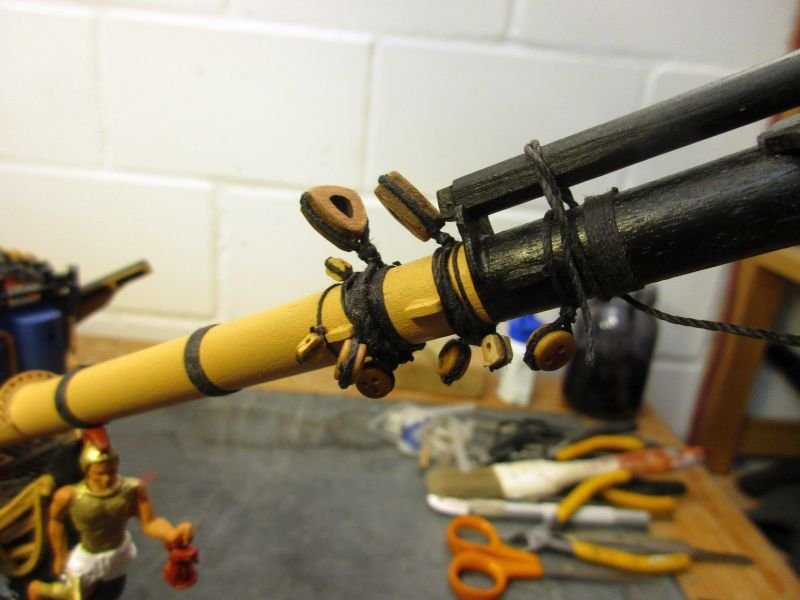
Below the bees I fixed some simplified bee blocks and the allocation of the caps eye bolts differs slightly from the instructions to leave room for manropes and jib boom horses. Not all went smoothly: The end of the bowsprit is round instead of square due me to overlooking wrong kit instructions - but that mistake should be covered by the cap. And the making of the stay collars was such a delightful task that I made 5 of them: no serving, wrong rope strength, wrong method of attachment. But for now I'm happy with the result and working on the yards.
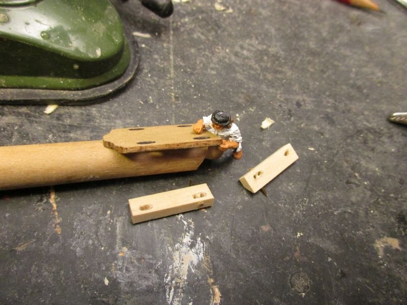
bowsprit end with simplified bee blocks
bee blocks and cap lavishly glued on (to cover the snags)
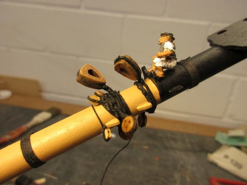
collars in place but main fore stay collar not served and the bobstay deadeyes collars wrongly spliced
approximately 4th attempt for stay collar
final arrangement of collars with jib boom provisionally in place
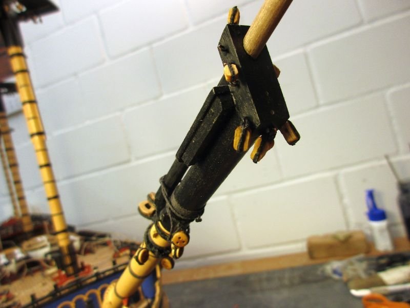
bees and cap
now only the two spritsail yards remain and then finally I may start rigging - yay!
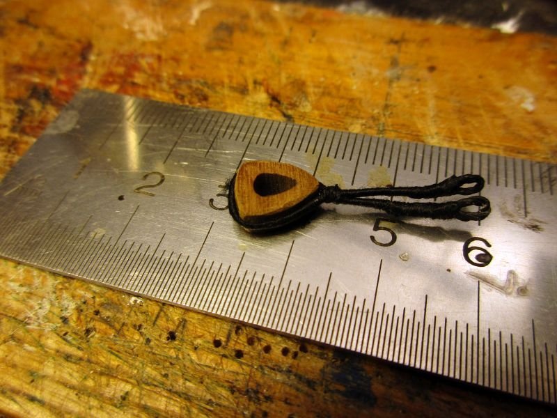
Dolphin striker and martingale stay
The 1786 Belerophon most probably didn't have a dolphin striker. According to Lees they were first introduced in 1794. However I think it possible that one was added later on, to support the jib boom. The piece provided with the kit resembles a dolphin striker of the very first generation, nailed onto the front of the cap, with just a score cut into its end for the martingale stay. This striker was in use up to 1800 - still according to Lees. Up to about 1805 martingale stay and martingale back stay were combined and led from the end of the jib boom to the notch in the end of the striker (this part was the martingale stay) and then further on to an eyebolt in the head (martingale back stay) to be set up with a fall.
Now the kits plans had me pondering. It showed such an early variant however with the backstay part set up with a fall just behind the bees. Nowhere in all my books I could confirm such an arrangement. Finally I found in Zu Mondfeld's book a sketch where the backstay part is led through a block near the collar of the fore preventer stay towards the head. Assuming that the designer of the kits rigging perhaps took a kind of a shortcut, but was close to the correct appearance, I think that this version would be a valuable solution. Where in the head the eyebolt for the fall should be placed, I wouldn't know. Lees states that it was set up on the bow, port side of the bowsprit. So, I think the lower part of the port knighthead might be a suitable place to put that eye bolt.
- AON, md1400cs, GrandpaPhil and 6 others
-
9
-
Hi Mitsuaki
Wonderful deck planking, really well done. Btw. I came to the same conclusion regarding the gangway planking.
Cheers
Peter
- Beef Wellington, AON, mtaylor and 1 other
-
4
-
-
Hi Mark
As always very clean fine work.
Just for your information: I had the same problem with the mizzen channel supports missing in the plan. However I didn't trust the stability without knees or something and placed 3 supports below the mizzen channel and one below the mizzen backstay stool. My carpenter and the bosun agree with me.
one support below the middle of each of the two aft most and one below the fore most pair of dead eyes, one below the centre of the stool
Cheers
Peter
- KurtH, chris watton, coxswain and 8 others
-
11
-
Hi Michael
Do you mean the decorative strip?
No big deal. The profile came right out of the box. Similar profiles would e.g. be available here:
https://www.cornwallmodelboats.co.uk/acatalog/Walnut-profiles.html
Cheers
Peter
-
28 foot pinnace
The assembly of the last of the boats followed the example of the others. The equipment includes rudder and tiller in addition to the kits oars, boathook and kedge anchor. Only the rowlocks hat to be made separately of 0,5mm wire as thole pins. They are not just notches in the capping as for the other boats.
I had the bosun try to rearrange all the boats on the beams and to fit them better between the rails guarding the waist. No success - he ended up the same way as before with the starboard rail only partly in place.
The hammock cranes along the waist on the starboard side were put in place and hammock nettings installed.
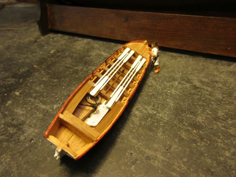
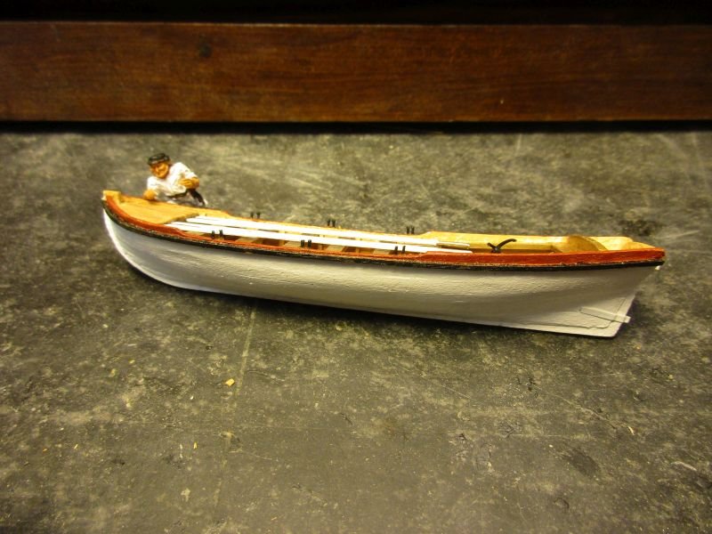
finished pinnace
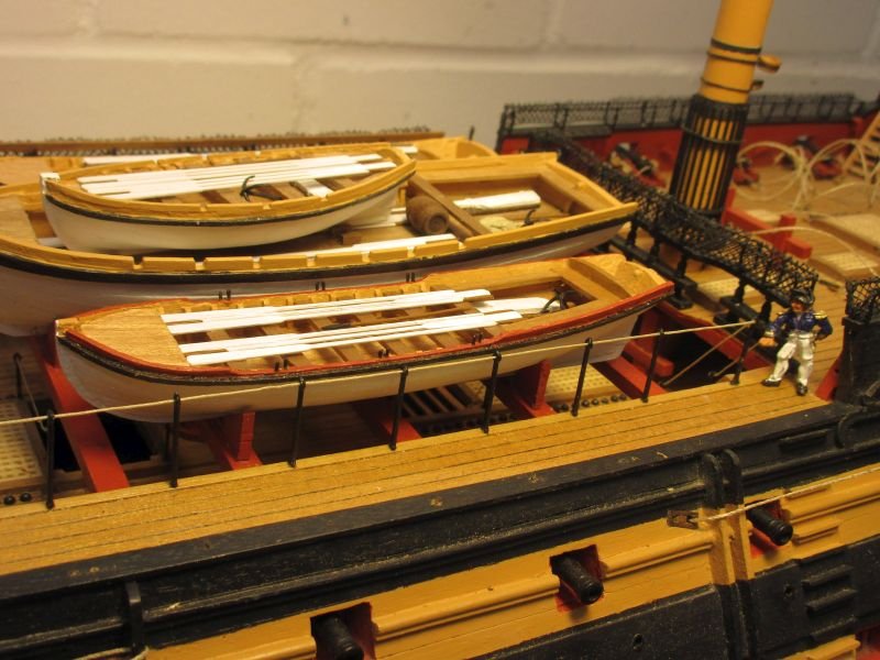
all boats on the beams
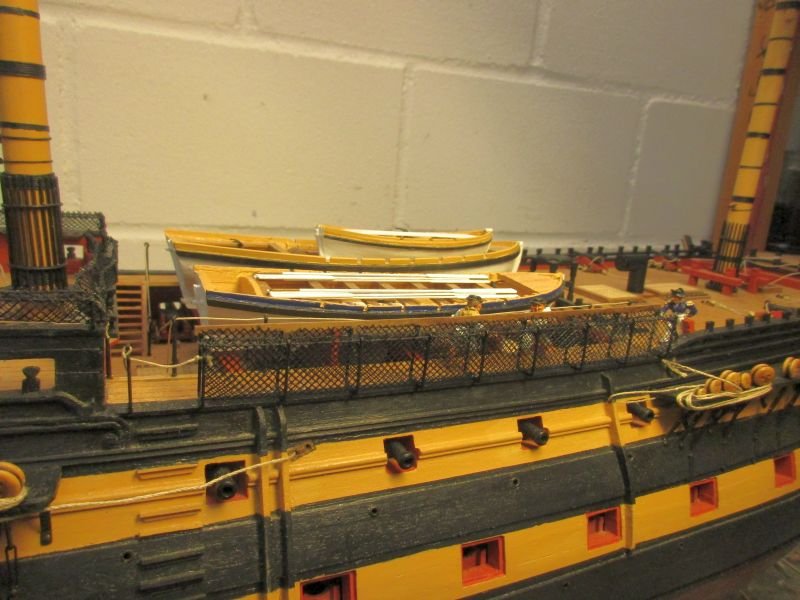
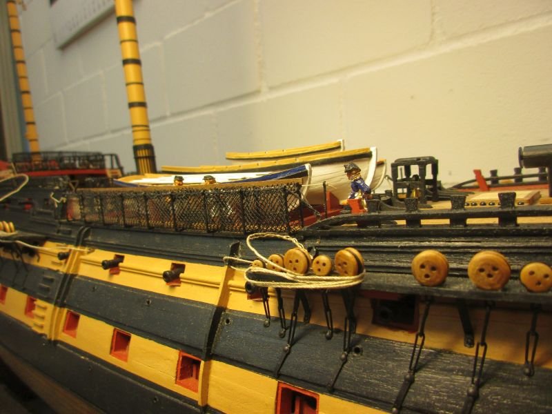
starboard hammock cranes finished
- marktiedens, md1400cs, egkb and 3 others
-
6
-
Hi Mobbsie
Long time no see - welcome back!
Surprise was always on my wish list however I've given up on JoTiKa's to be ever on the market.
But - have you seen the Sphinx kit Chris Watton is working on?
https://modelshipworld.com/topic/20737-chris-watton-and-vanguard-models-news-and-updates/page/43/
She was even a bit smaller than Surprise. With her 20 guns just large enough to be rated at all. But she looks a beauty, wouldn't use to much space and I'm sure Jack Aubrey met her once or twice during his career.
Take care
Peter
- mtaylor, Keith Black, mobbsie and 1 other
-
4
-
Hi B.E.
This solution of yours is very clever and looks really good. Presenting the model in a tangible situation with the details such as masts, sails, boats arranged accordingly ads plausibility. I prefer this to a somehow artificially admiralty model. Those are truly great as well, but also exceed my skill level.
Might I ask about how many ship models make your house filled up? Bellerophon is my 8th, but one was given away.
Cheers
Peter
- Martin W and Blue Ensign
-
2
-
Hi Meriadoc Brandybuck
Thank you.
Yes, however I think that generally space in Japan is much more limited than here. Despite that, my admiralty would object to fill all available space with ship models. Again, I guess, a known problem.
Anyhow Bellerophon will remain in the wharf for at least two more years...
Sayonara
Hi B.E
Thank you for the compliment but frankly one of my fixed lamps broke down and I had to improvise with a handheld one. So the result is just coincidence.
And thanks for the suggestion. Your Victory (Heller?) looks great. Did she just come back from cape Trafalgar? I like your way to present her much better than those sawed off mast stumps or nearly bare lower masts you occasionally see. It is an option but still I would like to set at least a few sails and I already laboured on those upper masts and yards...
Cheers
Peter
-
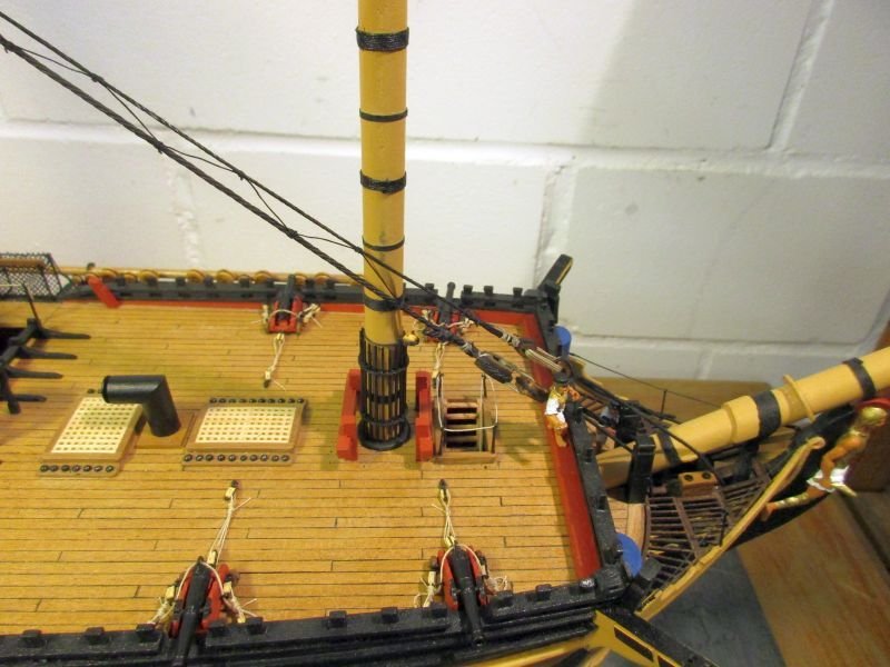
Fore mast
The fore mast and its yards were made similar to mizzen and main. While working on them I realized that about now it was time to put in those sheets which led through the sheave blocks and are belayed below the gangways. Anyhow I have to think about how to fix the boats on the beams. It seem advisable that they should be easily removable during setup of the rigging and perhaps even on the finished model to facilitate cleaning or repair work in the waist.
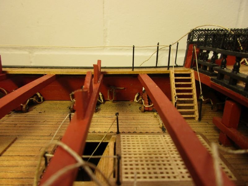
sheets belayed below gangway
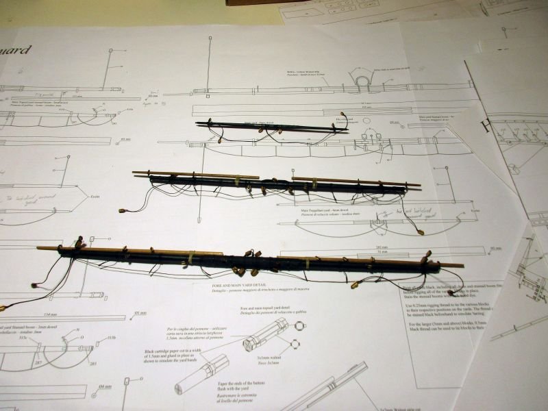
the 3 fore yards
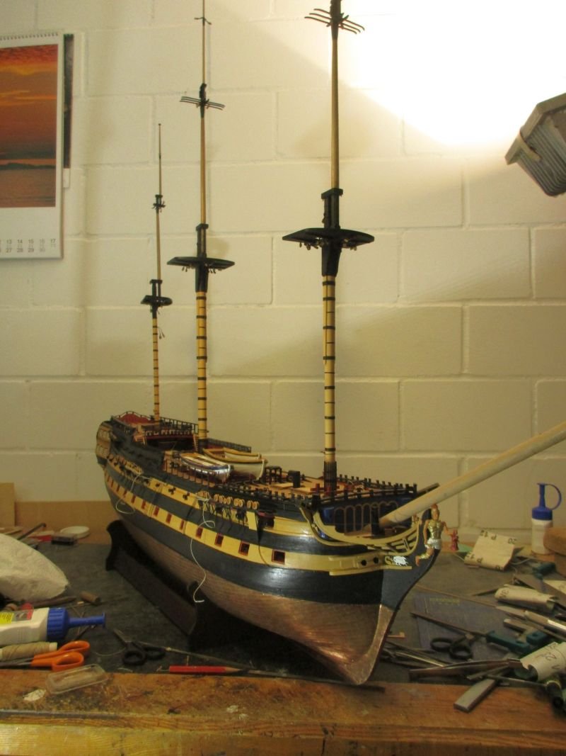
all 3 masts provisionally stepped
I'm having problems to place the whole model into one picture - still clueless where and how I shall place it when finished...
- Martin W, BenD, marktiedens and 7 others
-
10
-
Hi Michael
After silently admiring your build for a while I have to say how much I like it. Not only your unique realistic style shows but the added details depict again a masterpiece in the making.
The arrangement of the (too many?) guns below the fore castle left some doubts but I think EJ_L not only shares them but also shows a good solution. Not every gun port was always filled with a gun and leaving one pair off seems good to me.
In post #86 I see some scuppers. Did you drill them through to the outside?
Great work!
Cheers
Peter
-
-
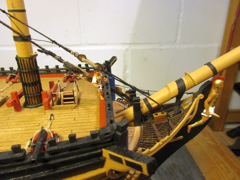
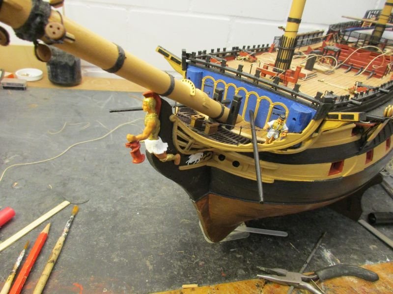
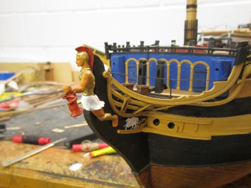
Bow and figure head
While working on the foremast and yards I frequently came across the figure head and realized that some additional work was required to 'marry' Bellerophon properly with the bow. Sitting on the simple step it looked more like a randomly placed passenger than a quite important part of the ship.
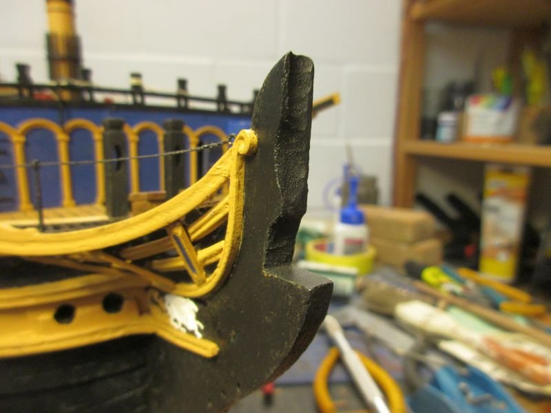
I started to gnaw at the bow with various instruments (file, Dremel, knife etc.) to make a snug seat which allowed back and head to be in contact with the bow. I'm sure those figures needed a tight sit as they were exposed to quite some weather. Bellerophon is still provisionally attached. With the final fixing I will see that no light will pass between bow and figure, making it more an integrated part of the bow than just an addition.
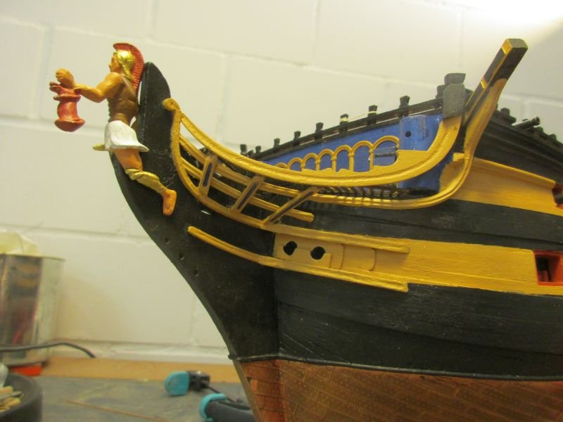
Bellerophon sitting rather exposed on the unmodified step
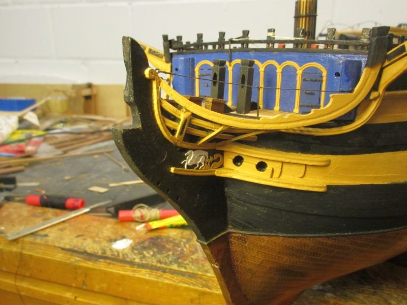
modified step
better fit
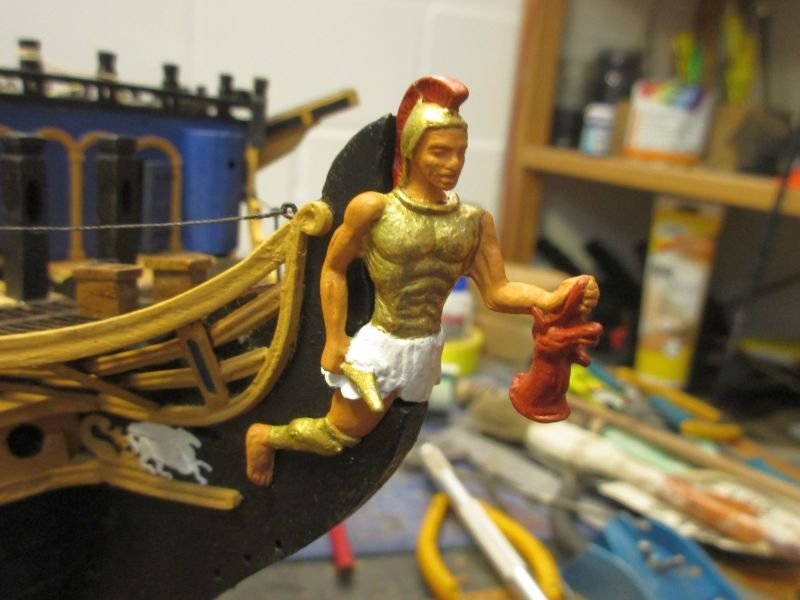
much better
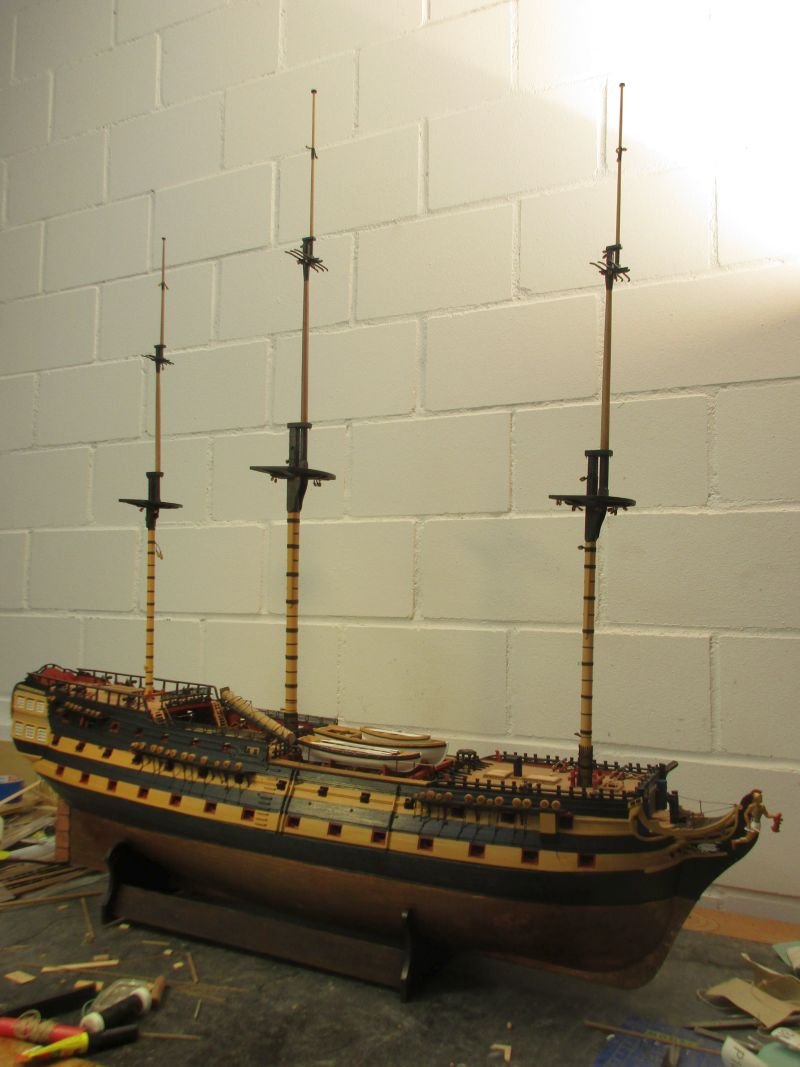
foremast is ready, still working on the yards
- egkb, BenD, GrandpaPhil and 5 others
-
8
-
Hi Mark
She's looking great.
The damaged grating at the bow... well, welcome to the club!
(I somehow fiddled some 1x1mm strips into the place of the broken parts.)
Cheers
Peter
-
-
Now, I'm a bit confused. I believe Spy has a lot of experience with actual sailing more modern craft but...
As far as I can see in my various sources, the lower mast was usually held back sufficiently by the shrouds while backstays were used to stabilize topmasts or topgallant masts. Setting up backstays to the lower mast would unnecessary complicate the rigging and the handling of the vessel while adding e.g. an additional pair of shrouds would be a much simpler solution.
I'm just a landlubber but Dr PR's diagrams in his excellent link seem to confirm my doubts.
Spy, could you dispel those doubts?
Cheers
Peter
-
Hi Mark
Wonderful clean work.
Regarding Franks question: I did put a simple chimney into the opening of the binnacle but when I just tried to see it below the overhang of the poop It was just barely visible and only because the rigging is not yet in place...
Cheers
Peter


HMS Pegasus 1776 by Moonbug - Amati/Victory Models - 1:64
in - Kit build logs for subjects built from 1751 - 1800
Posted
Hi Bug
You have been busy. Fantastic work.
Regarding the keel I thought it a good idea to have the keel protected by copper also on the underside. The false keel probably wasn't made from very high quality wood and after losing a part in an accidentally ground contact they would first have had to find a wharf to replace it. So that additional protection by copper would perhaps have paid off.
Being lazy however I usually copper only the underside which is not covered by the false keel.
Cheers
Peter