


DelF
-
Posts
1,398 -
Joined
-
Last visited
Content Type
Profiles
Forums
Gallery
Events
Posts posted by DelF
-
-
Rigging the spars - odds & sods
Many thanks for all the likes.
I had hoped to move on to the bowsprit by now, but some half-decent Autumn weather has kept me on various outdoor chores with only very limited time in the dockyard. Also, finishing off rigging the masts wasn't quite as straightforward as I'd expected, so I'll log another couple of wrinkles I've had to deal with.
First, I realise now that I was somewhat premature in gluing together the various components of the fore and main masts, the problem being that it now makes it more awkward to rig some of the required blocks. For example, a block and a thimble have to be set up on the fore topmast head as part of the rigging for the main topgallant and royal stays. With the fore topgallant mast and cap in place you can't just slip a loop of line over the masthead, and I found it impossible to seize the block or the thimble in situ. I resorted to cheating, which in this case meant seizing the block/thimble into the middle of a short length of line then tying the line round the masthead in such a way that the simple half knot was concealed in the gap between the masthead and the heel of the topgallant mast. A dab of CA and careful trimming with a scalpel and hopefully the 'cheat' is invisible:
Lift Blocks
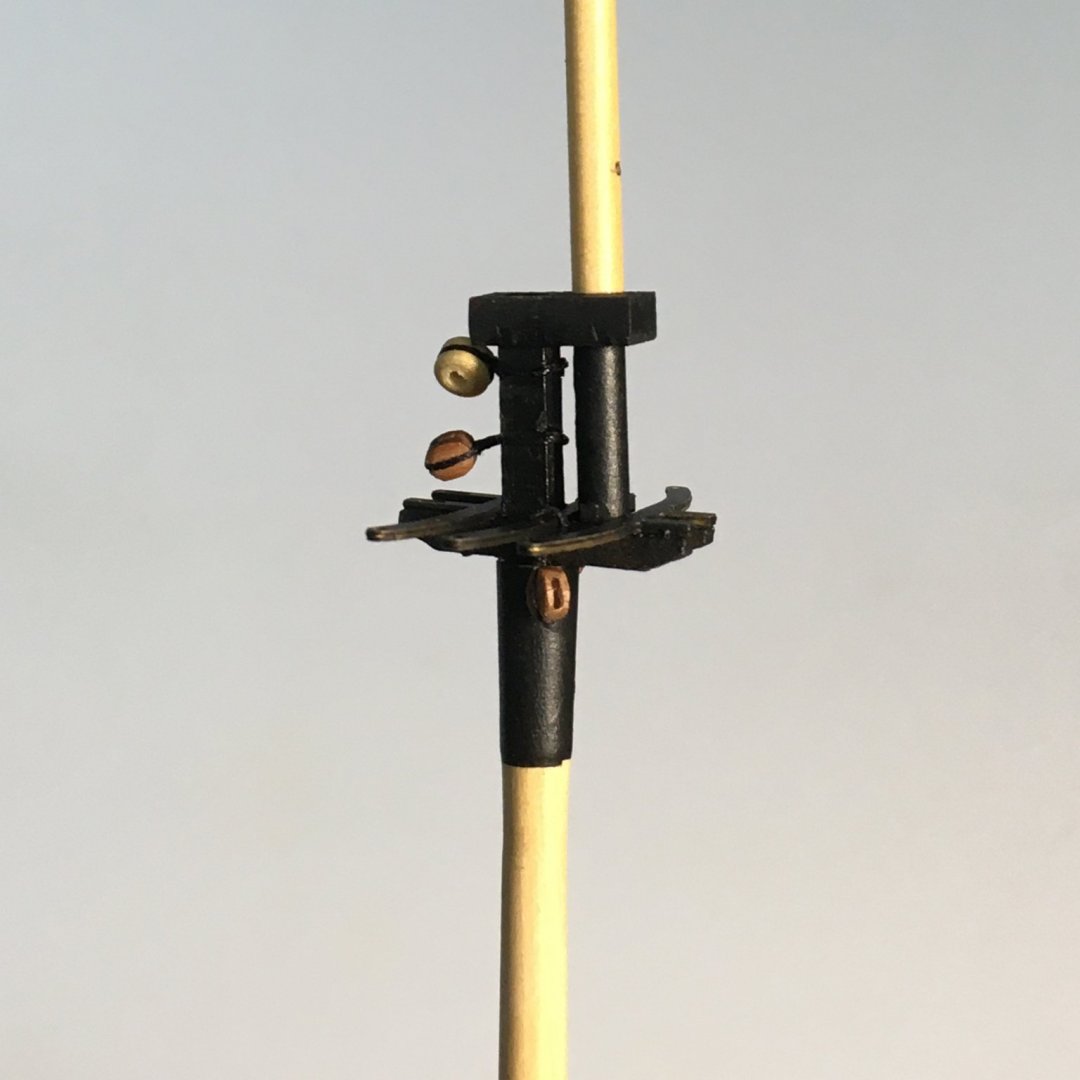
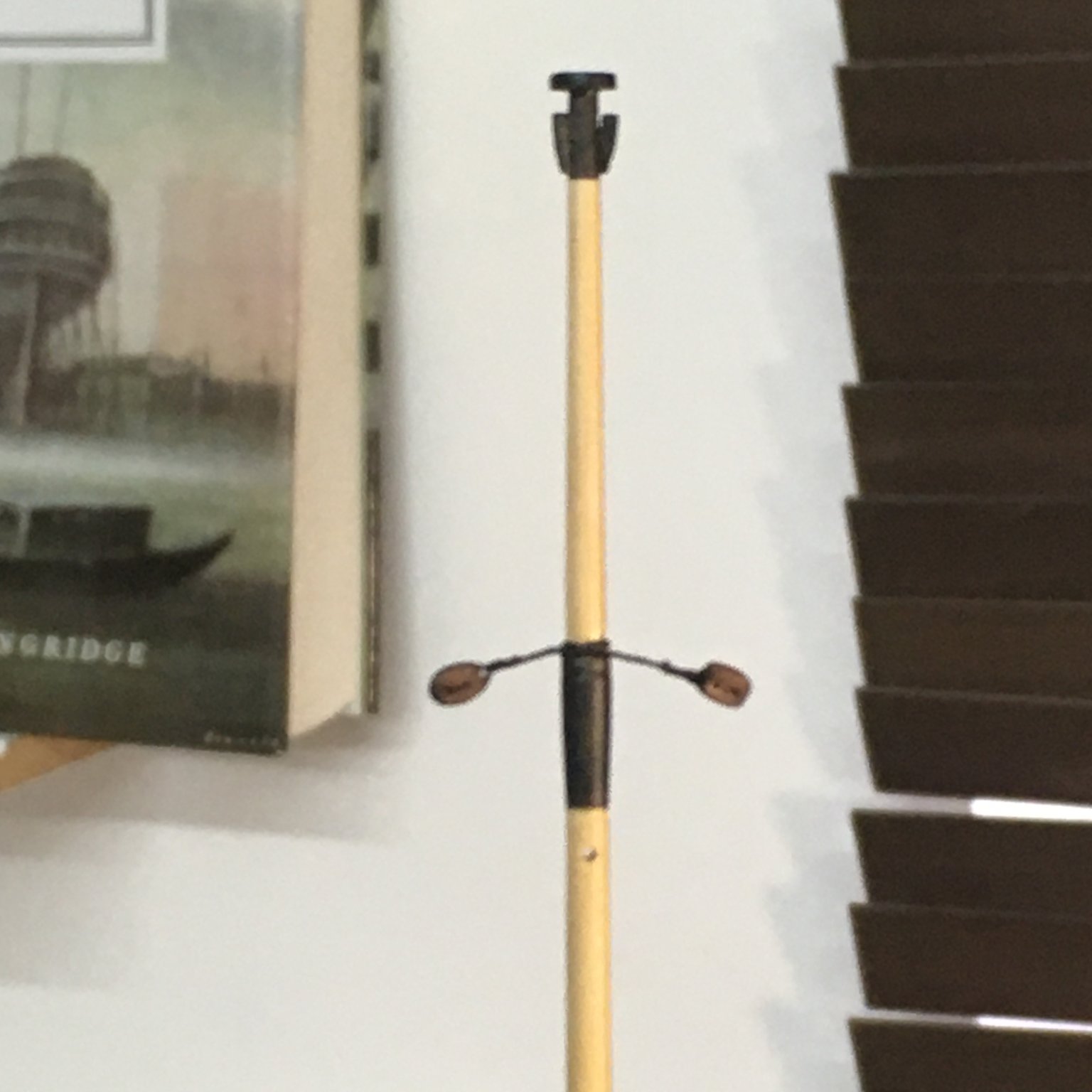
I had more substantial problems with the fore and main lift blocks. The kit shows these as pairs of long tackle ("fiddle") blocks seized into spans, ie lines that wrap around the main and fore caps. Impossible once everything is glued in place, as the gap between the mastheads and topmast heels is too narrow for the blocks to fit. A worse problem in my case was the quality of the fiddle blocks. These are the only components I have come across that fall below the otherwise very high standard in this kit. They were out of scale (at 7mm they should have been 1.4mm thick according to the ratios laid down, not 3mm), they were not well finished and the sheave holes and grooves were off-centre making them difficult to rig. I made my own fiddle blocks from boxwood for Royal Caroline and was going to do so for Speedy, but when I checked standard references (including Rees's The Masting & Rigging of English Ships of War) I found that ships of this period could be rigged with either fiddle blocks or ordinary double blocks. I opted for the latter. The only fly in the ointment was that Rees also noted that from 1760 blocks would be seized to an eyebolt in the cap rather than to a span. I was loathe to drill the caps for eyebolts at this stage so I chose to assume that Speedy's builders hadn't caught up with the changed instruction and fitted spans 😬.
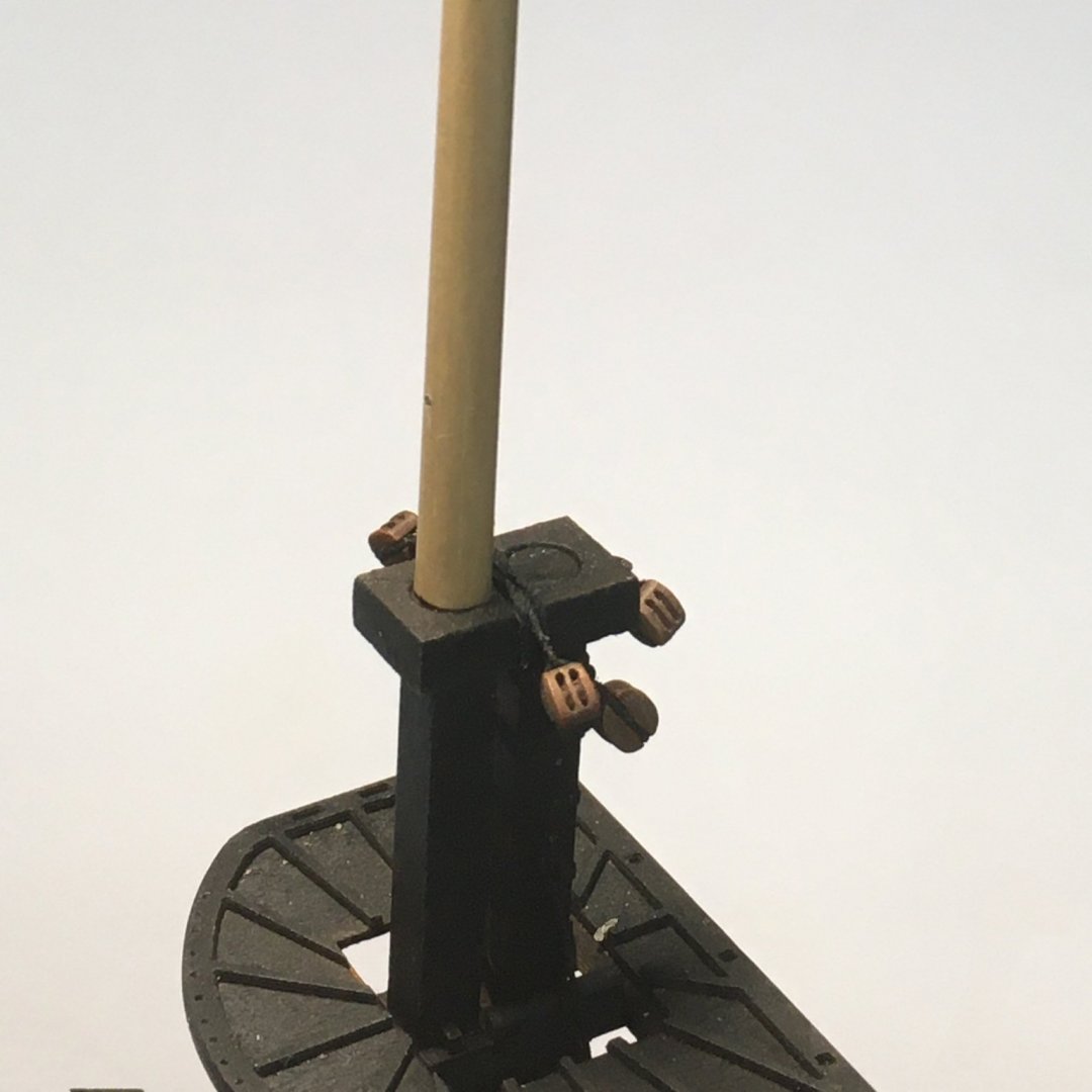
In this instance I was able to rig the span partly in situ. I started off the model by seizing a double block into one end of a line which I then set round the cap in a clove hitch as per full-size practice (I've got to do some things right!). It was then a relatively easy task to seize the second block into the free end of the span:
The clove hitch also came in handy when it came to setting up pairs of blocks at the topgallant heads:
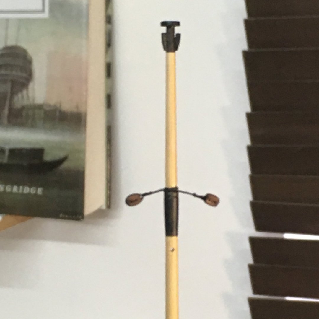
Much easier when you can get right round the spar in question!
Talking of knots, apart from the indispensable Ashley Book of Knots, my other goto reference is this website Animated Knots by Grog. Worth checking out if you've not used it.
One final point before I forget - I've found that the sheave holes in the blocks are only just big enough for their intended line. To avoid any problems in rigging on the ship, I've been drilling them all out to a very slightly wider diameter as I fit them to the various spars.
On to the bowsprit.
Derek
- Edwardkenway, VTHokiEE, usedtosail and 5 others
-
 8
8
-
1 hour ago, glbarlow said:
So what are the grits of your sandpaper row? So you put honing fluid on sandpaper?
They range from 180 through 400, 600, 1,200, 1,800 to 8,000. I've got finer ones but I rarely go beyond 1,800. Btw, I read somewhere that European and American grit sizes are different, but I checked that these figures I've quoted are American. I use the honing fluid on the sandpaper but it's not necessary so long as you have some form of lubrication. From memory, I think Paul Seller uses automotive glass cleaner in a spray bottle.
1 hour ago, glbarlow said:I’m not a complete poser.
Mmmm. I've seen your 1:48 version....
Derek
-
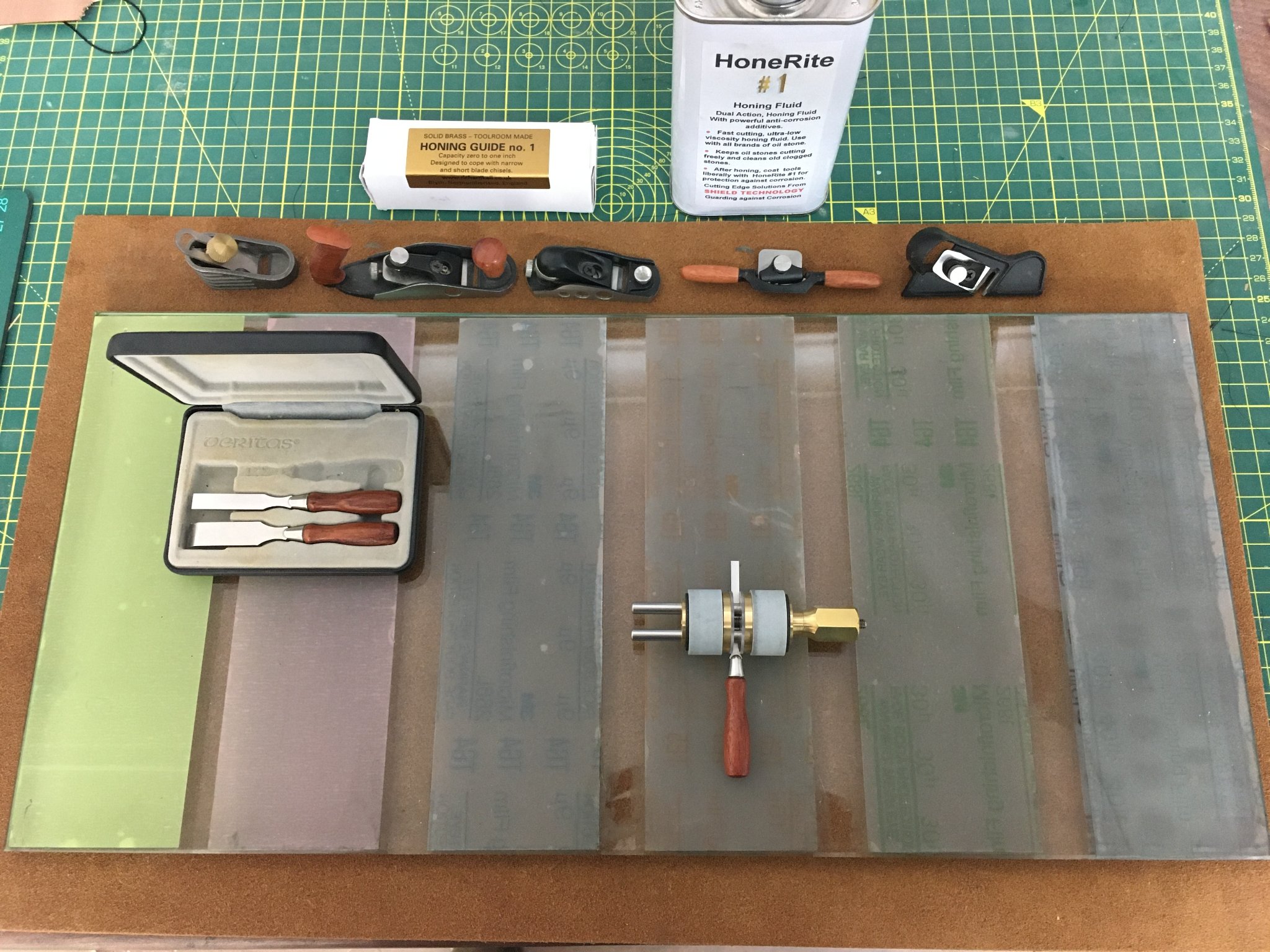
Glenn, I have the Veritas guide John mentions. Like all Veritas products it is well made, but with very narrow chisels I find it can be difficult to get the blade to sit absolutely square, and with a single roller it can be difficult to avoid the blade rocking as you move it up and down the sharpening surface.
The best guide I've found for these blades is the No.1 Honing Guide from Richard Kell. Richard is a one-man-band based in Northumberland, although his products are available through US retailers. Here it is on my sharpening station (I couldn't resist including my collection of Veritas tools
 !):
!):

The key feature is that the blade is clamped between two rollers and so is held dead square. I've got the 1/8" chisel in it, but it will take up to 1". Because there are two rollers it doesn't rock, and because you can mount a blade under the two steel guide rods as well as over them, it can handle very short blades which otherwise wouldn't project far enough from the guide to get the correct honing angle. I've found it for sale on this US site, but if you look on Richard's own site under <links> you will find others. I ordered mine direct from Richard which may be another possibility if it is out of stock at your retailers.
A couple of other points. You'll see from the photo that I've abandoned traditional sharpening stones in favour of sandpaper. Stones inevitably wear and need to be reground or replaced. So does sandpaper, but it is considerably cheaper and, when glued to 1/4" plate glass it stays dead flat. Plus, it is easier (and cheaper) to have a wide range of grits to suit your needs.
Another point - and I apologise if this is teaching granny to suck eggs - but when you say you haven't sharpened your chisels yet it occurred to me that you might not realise that chisel and plane blades bought straight from the manufacturer are not best suited for immediate use. They need a degree of preparation, sometimes called initialisation - even Veritas tools! This takes a bit of work on the sharpening station but once done it becomes quick and easy to hone your blades back to perfect sharpness. Paul Sellers does the best videos I know on woodworking - here's his explanation of initialising new chisels. Interestingly, Paul is using three sharpening stones in this three year old video - he now uses sandpaper.
If you decide to set up a sharpening station like this you'll find you will be much more inclined to keep all your blades in tiptop condition, and you'll be surprised just how much difference truly sharp tools will make. They will slice through wood with minimum effort, and will make woods like box a joy to work with. Remember the difference you found when you switched to Vallorbe Swiss files? You'll find a comparable difference between tools straight out of the box and properly sharpened tools.
Sorry to hog your log.
Derek
-
Btw, I see you have a set of Veritas miniature chisels - some of my favourite tools. They take a very keen edge with careful sharpening. How do you find them?
-
Really superb Glenn. I particularly like the third shot up from the bottom - the one from low down on the starboard stern - as it shows off the lines of the hull and the quality of your workmanship beautifully. As Edward says, the mouldings are spot on - the boxwood goes well with the cedar, and is a lovely wood to work with. Great stuff.
Derek
-
Excellent result Tim - well-rigged guns really add a huge amount to the visual impact. Well done!
Derek
-
9 hours ago, whitejamest said:
Did you sand the MDF adjacent to where the sternpost gets attached prior to beginning the planking?
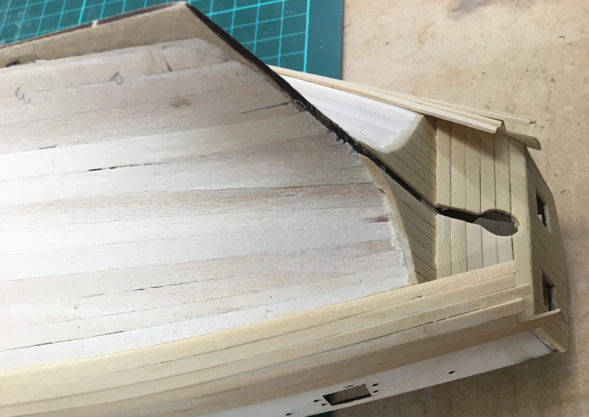
No, although that might work if you were careful. In my photo you can see that some of the MDF has been sanded down, especially at the point. That was unintentional - I did it when sanding the planking. However it wasn't a problem - you can easily lose mistakes like that under second planking and coppering. As I said before, filler is your friend!
The crucial point is to make sure that the combined width of the MDF and planking at the stern is the same as the width of the sternpost. You want the hull planking to flow smoothly into the sternpost so there is no obvious step or angle where they join. That's why the manual suggests that, before second planking, you file/sand the sternpost area to 1.5mm so that when you apply the second planking it sits flush with the sternpost.
Derek
-
Rigging the spars - stropping blocks
Thanks as always for the likes and kind comments.
I should have said earlier, but one reason I'm not giving a blow-by-blow account of the rigging is that I've decided to follow the kit plans fairly closely, so anyone else building the model would learn little. On my previous fully-rigged ship, Royal Caroline, I did extensive research through the AOTS book on the royal yacht, Lees's Masting & Rigging and The Fully Framed Model (the 4th volume is great on rigging a 6th rate similar to RC). But that was primarily because the kit plans were so simplified and/or inaccurate, whereas I'm sure Chris has done the research needed to produce an accurate rigging plan for Speedy (so far as that is possible at 200+ years remove!). If I do decide to enhance the rigging in any way - anchor buoys is one possibility - I'll cover that in due course.
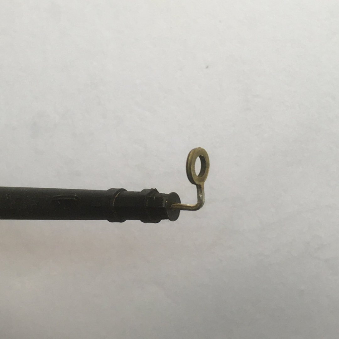
Meanwhile I'll just stick to logging any unusual points, or points that might be of more general interest. Given that there are over 130 blocks and deadeyes to fit, I thought I'd say a little about the methods I'm using to strop them and fix them to the spars. Previously I mentioned the simple method I'm using where a block attaches directly to a yard (link here). However this method isn't always appropriate, for example where the knot would be visible or where you need more separation between the block and the spar. There are lots of ways people have developed to skin this particular cat; some, such as following full-size practice by making strops out of line spliced into seamless rings, lie outside my skill set. In the end I went for a variation on a method I first saw as a video, which in turn was based on this forum post by Bender. This technique works fine for larger blocks, but I found it fiddly for the many 3mm tiddlers on Speedy, and I thought the end result looked a bit clunky.
For my slightly modified method I used (for 3mm blocks) 0.25mm black line from the kit, 18/0 fly tying thread (as previously described) and thin CA. I normally use fly tying cement to fix rigging knots, but in this instance I decided I needed the added security of CA. This is because the seizing formed by the fly tying thread will only be 1 to 2mm wide and will need to hold the strop in place against any tension in the rigging.
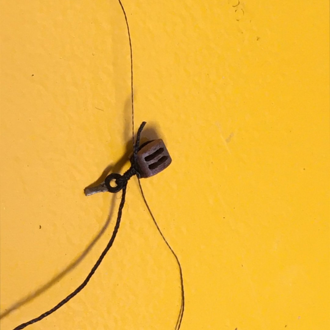
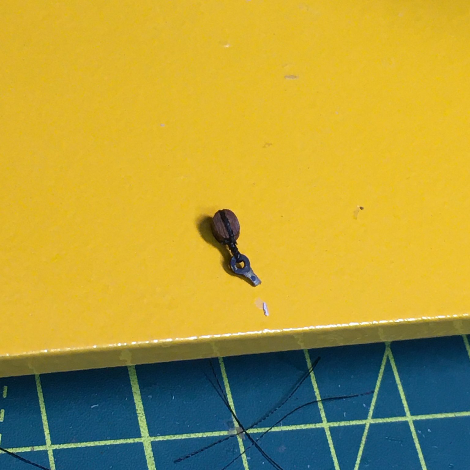
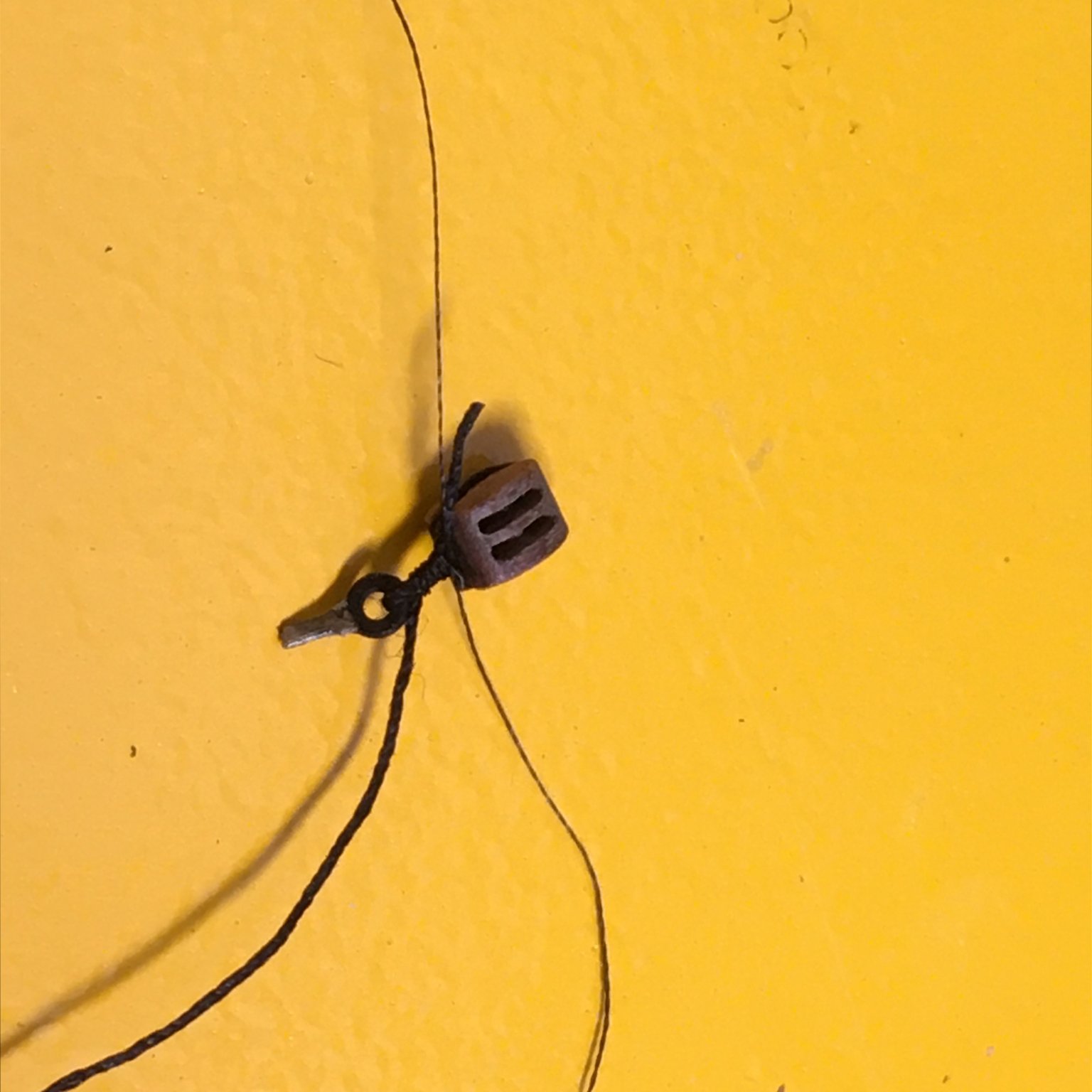
I started by seizing the block into a length of 0.25mm line, using the method I described when I was rigging the guns - ie knotting the thread alternatively above and below the line (link here). It can be difficult to snug the seizing tight up against the block, especially with thicker line, so I tried a couple of approaches. In the first picture below, I started the seizing a couple of mill away from the block and worked the seizing towards the block; in the second I wet the line with water and pinched it round the block with tweezers to get it to conform to the shape of the block better, then began the seizing as close as I could to the block and worked away:
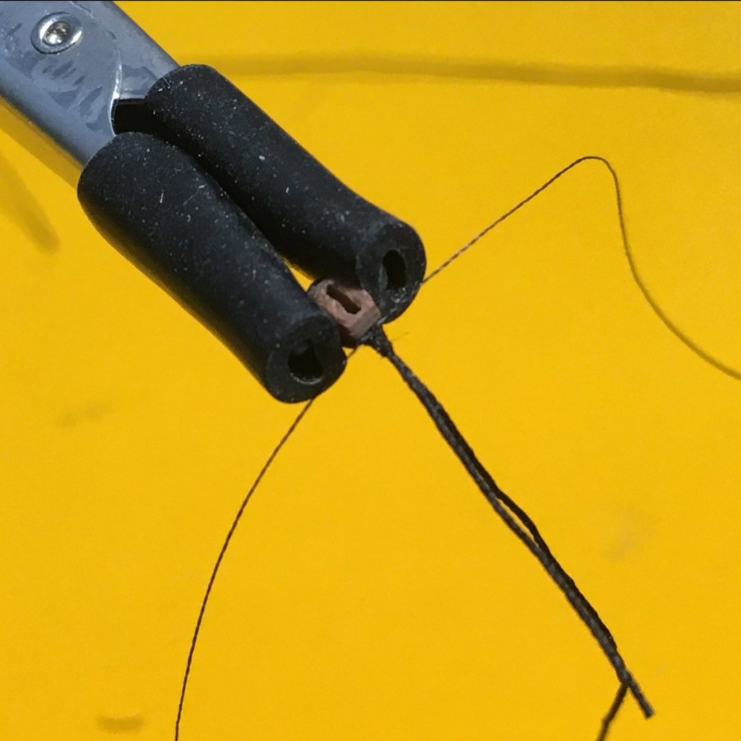
The second result looks neater, and will produce a less clunky end product. In this example I'm seizing the block to a ring, so the next step is to thread the short length of line through the ring (much easier off the model!), fold it back over the block and hold the block and line together in the clip (unfortunately I only photographed this stage for the first seizing method, but the idea is the same):
The trick here is to fold back the line just enough to produce the gap you want between the block and the fitting.
Next, I repeated the over and under seizing, this time including the folded back line (this photo shows the result using a block stropped using the second seizing method):
After a tiny drop of thin CA and trimming:
The method works equally well with double blocks:
One variation that I touched on briefly before is where you need a ring in the strop. Initially I used a 1mm drill bit to make the ring but after deciding it was too large I substituted a 0.8mm needle. Soaking the rings in thin CA seems to keep their shape - you just have to be careful to move the line on the needle before it sets! Here, I'm doing four at once:
Economising
I started cutting 100mm/4 inch lengths of line for each strop but decided this was wasteful. Instead, I just used one end of a longer line, trimming it off close to the seizing when the CA had hardened. In this way I used less than 30 mm of line for each strop. May seem like penny pinching, but it actually makes your line go three times further.
By the way I can imagine some experienced modellers turning up their eyes at what they see as obvious points about rigging, but none of this stuff was obvious to me when I started, and if it helps one or two people then I'm happy.
I'm moving on to the bowsprit next which brings its own interesting challenges, for example with collars with one, two and four deadeyes seized into them. I'll cover that next.
Derek
- ccoyle, Nunnehi (Don), egkb and 10 others
-
13
-
Very good first planking James. You're right that you don't need to cover all the MDF at the stern. On the other hand you need to make sure the planks merge smoothly into the MDF, especially the second planking, otherwise you'll end up with a step. Here's mine after sanding:

I think there are similar photos in the kit manual. Unfortunately you do have to sand off a good deal of wood to get the desired result (alternatively filler can be a life saver in first planking!).
Anyway, well done. You've produced a sound base for your second planking.
Derek
-
14 hours ago, glbarlow said:
made for a dirty shirt
Furloughed the valet after all I see 😂🤣
- Edwardkenway, glbarlow and mtaylor
-
2
-
 1
1
-
-
-
On 9/12/2020 at 4:34 PM, No Idea said:
I like mine but find the indexing is not that accurate.
I'm surprised, as I find the Proxxon mill very accurate. Have you tried adjusting the gib strips to eliminate any play in the 3 axes? I've not had any problem with backlash with mine, but if it an issue I suspect there's information on the web on how to eliminate it.
Derek
-
Well done Gerry!
That’s a great job on the first planking. I wouldn’t say you are slow - you clearly work steadily and carefully and the results show. You’ve produced a perfect base for the second planking.
Derek
-
The kit supplied barrels are far too big. I replaced them with these 28mm ones from Amati. You can get them with carriages, but I made my own. To my eye they look in proportion, unlike the original cannon:
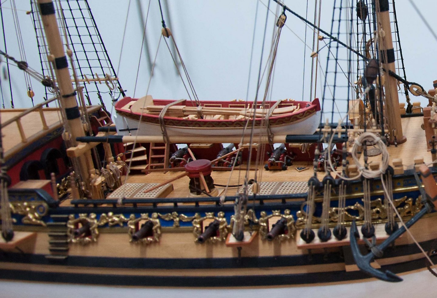
Trouble is, the AOS book is such a good reference source that you'll find yourself wanting to enhance the kit in lots of other ways. Don't get me wrong - the kit makes up into a fine and decorative model, but for me part of the fun in this hobby is looking for ways of enhancing kits to make them more historically accurate and realistic and to increase my own skills and enjoyment. There are far better examples of Royal Caroline on the forum than mine - for example check out those by Marsalv and Doris.
Derek
- chris watton and mtaylor
-
2
-
Congratulations on completing a lovely model - the figures really bring her to life.
Not bad for a 168 year-old! 🤪
13 minutes ago, Bill97 said:I was 6 years in 1858.
Derek
- shipman and Ryland Craze
-
2
-
40 minutes ago, glbarlow said:
106 F, 41 C
Wow, that’s hot! The UK Record is 38.7 C/ 101.7 F set in July last year - and not in North Yorkshire! It got close to 100 where I live - I was painting a fence that day and had to retreat indoors for several restorative beers.
44 minutes ago, glbarlow said:the paste is something I’ll definitely try,
Great - it’s so useful for many aspects of our hobby.
Derek
-
19 hours ago, Blue Ensign said:
Envious of your Whitby trip
Glad to see from your Muirneag log that you were able to get a break in Devon - now I'm envious!
Derek
-
Sjors,
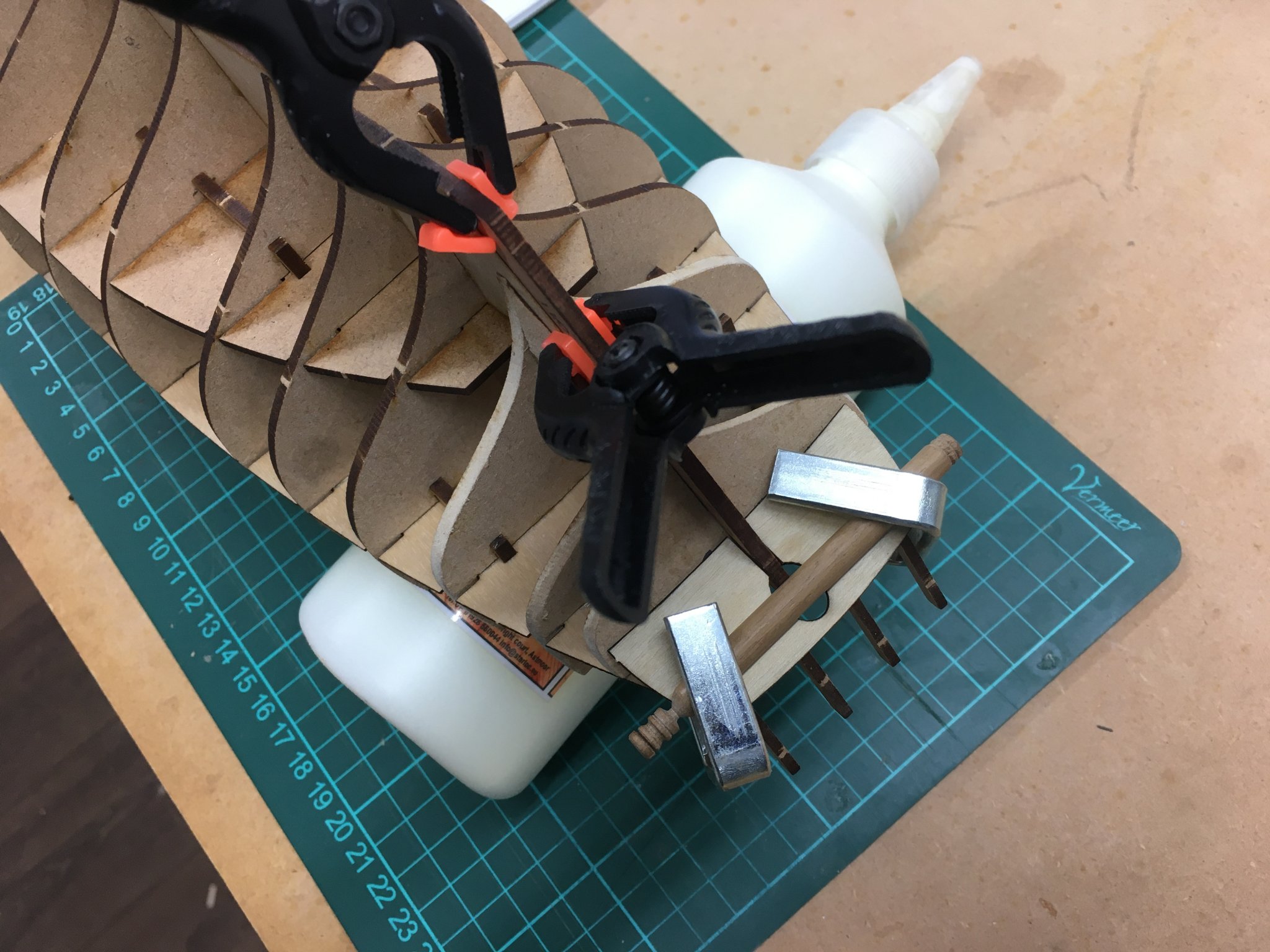
I also found the stern counter timbers tricky, although I did manage to impart a curve to the stern counter by clamping it whilst it was drying:
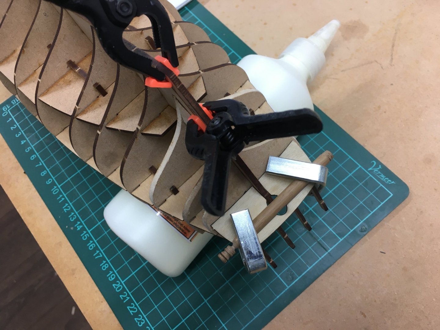
Here's a link to my Speedy log where I fitted the stern counter timbers.
12 hours ago, dkuehn said:My wales took up most of the space and the boom crutch parts 128 tied into the wales so I left it at that.
I agree with dkuehn - if you can get the boom crutch to tie in neatly with the wales it will look fine. However if you can fit the stern counter timber as intended it will be even better.
Derek
- Edwardkenway, mtaylor, glbarlow and 3 others
-
6
-
She’s really coming to life now Glenn. As Edward says, that shade of red looks just right to complement the timber.
I also bought the Amati scrapers. I suspect they’ll languish in a drawer for some time before I find a use for them.
Derek
- mtaylor and Edwardkenway
-
2
-
Rigging the spars - silver soldering repairs!
Back in the dockyard after R&R in North Yorkshire. I'm still working on rigging the 130+ blocks and deadeyes required on the masts and yards. Rather than a string of posts setting out repetitive detail I'll just focus on any out-of-the-ordinary points.
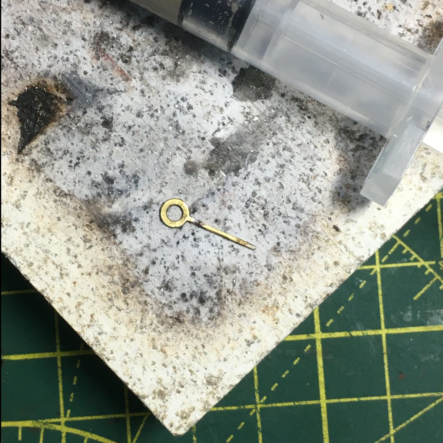
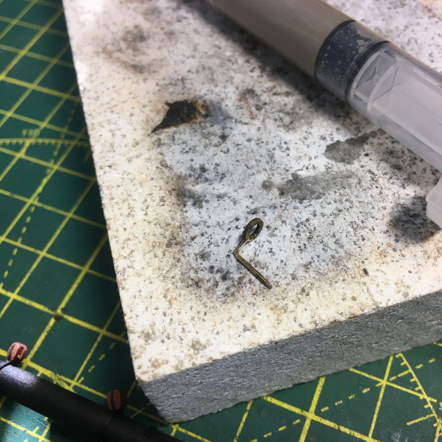
First up, a spot of repair work caused by clumsiness, whereby I managed to break one of the stunsail boom irons on the main yard. These components start out as flat pieces of photo-etch, with a score mark that enables you to bend them into a right angle:
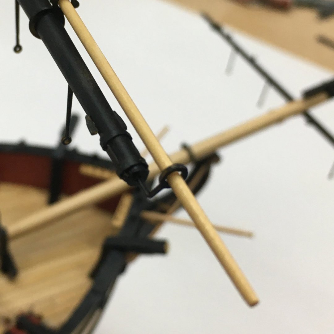
The score mark is a weak point, and unfortunately I bent the boom iron in question a couple of times by mistake when rigging the yard and I had to bend it back into shape once too often. I considered making a new iron from scratch but decided instead to try soldering the bits back together.
Silver soldering has become one of my favourite techniques for joining metal. I struggled with it initially until I discovered silver solder paste. This does away with the need for separate fluxes and solder and makes the whole process so much easier, at least for the tiny components I work with. I suspect model railway engineers handling large chunks of brass might have a different perspective! Here's the kit I use:
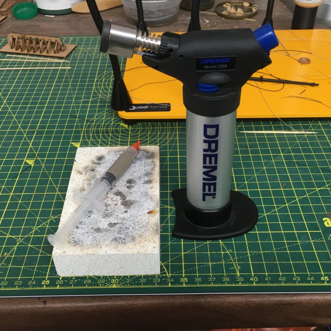
Along with the paste is a refillable gas torch and a fireproof brick. All are readily available from jewellers' suppliers and elsewhere. The paste comes in small tubes - usually about 10g - and seems quite expensive (eg here). However I've had mine years, soldered literally hundreds of items with it, and I hardly seem to have used any. For the boom iron I used a tiny speck, smaller than a pinhead. You can buy different grades of paste, usually rated easy, medium and hard depending on the temperature they flow at. That's an issue if you have to solder a joint close to an existing joint, the idea being that you do the first joint with a higher melting point solder than the second joint, so you don't disturb the first when you solder the second. However that is rarely an issue - I get by with 'easy' solder 99% of the time.
There's lots of information and how-to videos on the web, but for me the key points are that the surfaces to be joined must be clean and in close contact. I used a fine file to clean the boom iron and laid the two pieces flat on the fire brick, touching and with the tiny blob of solder sitting on top of the join. With such tiny components I don't apply the heat directly to the work. If I did, the gas jet would probably blow the components off the fire brick and/or melt the brass. Instead, I aim the flame about one inch to the side of the work then slowly move it closer, circling round to heat the work evenly. You'll know when the work is hot enough, because the paste suddenly liquifies and is wicked into the join.
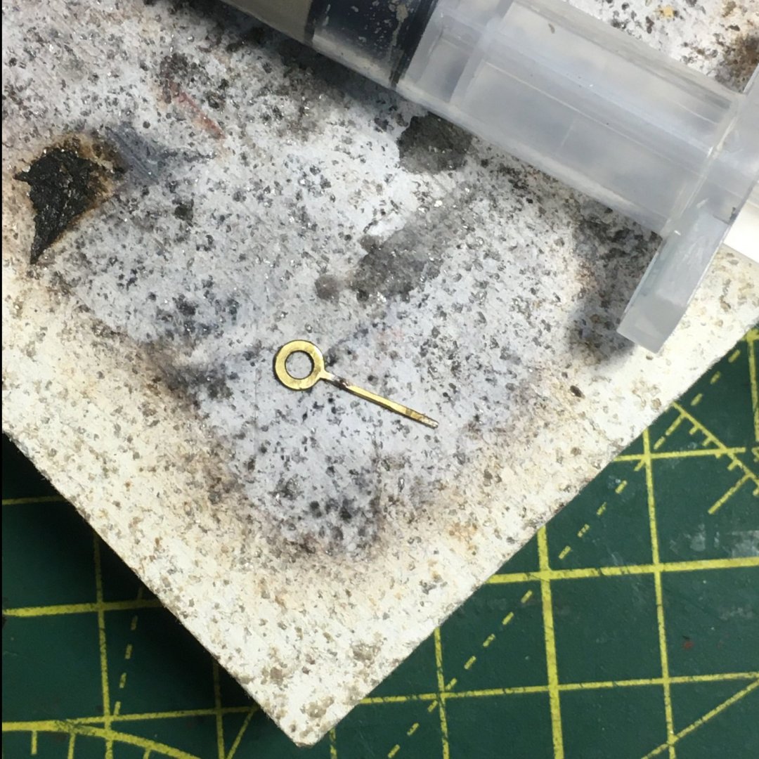
It takes a bit of practice to get a 'feel' for this - for getting just the right amount of heat to the work without melting it - but it's a lot easier to master than I thought it would be, and once you've got the hang of it it's a doddle.
One of the great things about silver soldered joints is their strength. Once I'd soldered the boom iron I was able to bend it back into shape , confident that it would be as strong as an unbroken piece of brass.
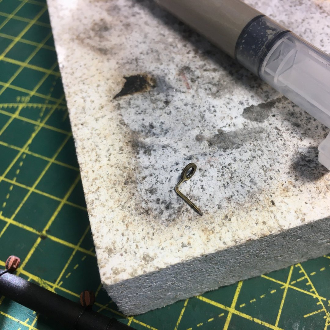
If you've not tried silver soldering, or if you've tried it and given it up as too difficult (as I almost did), then I'd encourage you to give it a go. As I said, the game changer for me was silver solder paste.
Hope this was of some interest.
Derek
-
Looking good! If there was an award for the fastest Flirt/Speedy build you'd be a shoo-in.
- Edwardkenway and dkuehn
-
2
-
Hi Tim. I think the length looks about right - any longer and it might droop to much on the deck. I changed my mind on the side tackle on Speedy at least three times, so I know what you're going through!
Derek
-


HMS Speedy by Delf - FINISHED - Vanguard Models - Scale 1:64 - Master Shipwright edition
in - Kit build logs for subjects built from 1751 - 1800
Posted
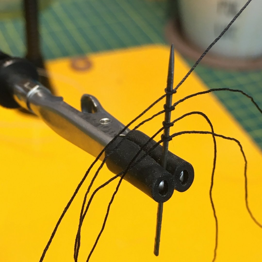
No, I'm using the quadhands to hold them while I work on them. One of the best pieces of kit I've got in ages. Sorry to hear about the water leak - nightmare!