
DONATION DRIVE - SUPPORT MSW - DO YOUR PART TO KEEP THIS GREAT FORUM GOING!
×


druxey
-
Posts
13,353 -
Joined
-
Last visited
Content Type
Profiles
Forums
Gallery
Events
Everything posted by druxey
-

Echo by Maury S - FINISHED - Cross-Section
druxey replied to Maury S's topic in - Build logs for subjects built 1751 - 1800
Those beam arms look nice! -
Actually, that is a very good 'teaser' for what we hope will come! Thank you for your history, both personal and that of the Museum. The web site is interesting and informative, but might I suggest proofreading the text?
- 33 replies
-
- 1
-

-
- warspite
- battleships
- (and 1 more)
-
HMS Naiad 1797 by albert - FINISHED - 1/48
druxey replied to albert's topic in - Build logs for subjects built 1751 - 1800
Lovely work, Albert! And a very nice workshop as well. -
Glad we solved that mystery. I can sleep tonight now!
-
What this means is that the line of the change in plank thickness is continuous, and doesn't jog up and down with the actual edge of the sheer strake. It's your 'other interpretation', Toni.
-
The NRG annual Conference in St Louis 2014.
druxey replied to Chuck's topic in NAUTICAL RESEARCH GUILD - News & Information
I guess we'll recognize each other by our avatars? -
Meillieurs souhaits a votre vernissage, Gaetan! (Congratulations on your exhibition, Gaetan). Looks terrific. I hope you had a good audience and turn-out to your show.
-
I agree with Gary's assessment. Look at the rabbet as shown on the deck plan. It appears within the width of the stem, rather than at its aft edge. What is unusual is that the stem/apron joint line is shown as a dashed one on the sheer and profile. Usually joint lines are delineated as solid lines on these draughts. I think that is what threw us. I suppose it was the draftsman's way of demonstrating that the rabbet progressively moved forward of this joint as it moved up the stem.
-
Alex: that's exactly the reason I asked whether the plan was an 'as built' one or not.
-
John: that's an interesting photo; the holes are on all faces, but offset from each other. As you say, later; but a nice example!
-
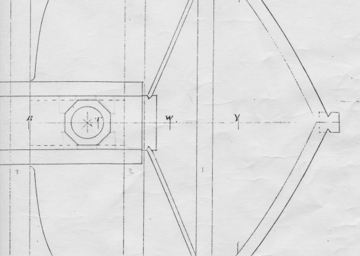
Deck plans of Revenue cutters I've looked at show (where bar holes are indicated at all) that these are on every other face. If you think about it, it makes sense. Holes in every face would weaken the windlass when strain was placed against one side of the hole and there was little wood between it and the next hole. The few models where photos show the windlass: the same applies. However, it's your call, Chuck.
-
I'll do some digging, Chuck. Either way, it's a beautiful windlass!
-
Enjoy the movie, Dad: your optic receptors for pink and purple will probably burn out.... That is an ingenious solution to making a windlass. Well done! However, are the bar holes on all octagonal faces or should they be only on alternate ones?
- 1,051 replies
-
- 1
-
-
- cheerful
- Syren Ship Model Company
- (and 1 more)
-
I'm not happy with the explanation, gentlemen. If the difference between the dashed line and inner rabbet line is the thickness of the frame - or bollard timber - one would expect the distance between those lines to increase the further down one goes, not have it taper out to nothing. This need further examination.
-
Is the drawing an 'as designed', 'as built' or ' as altered'? Or is there no clue on the drawing as to which of these it might be?
-
All the frames, etc., are fully lofted on the plan set, Alessandro.
-
What calibre, date and length are the cannons you are looking for?
-
The author will be giving a talk on this fireship at the upcoming NRG Conference as well.
-
You will still need to check fairness with some buttock lines and proof diagonals, Alan.
-
I agree: contemporary models show these also in white.
-
Can i live without a BYRNES TABLE SAW
druxey replied to shihawk's topic in Modeling tools and Workshop Equipment
Never buy a cheapie. It's a snare and delusion. You'll never regret getting a quality tool, be it machine or hand tool. -
ROYAL CAROLINE 1749 by Doris - 1:40 - CARD
druxey replied to DORIS's topic in - Build logs for subjects built 1501 - 1750
Best wishes as you seek a new job, Doris. The model(s) look lovely.- 883 replies
-
- 1
-
-
- royal caroline
- ship of the line
- (and 1 more)
-
18th century plank lengths were generally 24' 0" to 28' 0".