


Bob Cleek
-
Posts
3,374 -
Joined
-
Last visited
Content Type
Profiles
Forums
Gallery
Events
Posts posted by Bob Cleek
-
-
Welcome! It sounds like you're going about things properly and you'll end up with a fine model.
Just a few random "tricks of the trade" I wish I'd learned earlier than I did: You may already be aware, but I'll mention that you should sand or scrape off the char from the laser cutting on any parts that will show, even if painted, and especially remove it from all faying surfaces. Paint and glue don't hold as well on the charred surfaces. Also, PVA can be softened and removed by applying isopropyl alcohol. (Wrap the joint in a bit of paper toweling which will keep the alcohol in contact with the PVA.) The primary advantage of PVA over CA is its reversibility. There will be mistakes! It goes with the territory. (I'm told there are "reversers" available to remove CA, but I'd file that under "Good luck with that!)
In a build like this one, clean, sharp pieces are important. If you seal all your wood with clear ("white") shellac, the basswood parts will not "fuzz" when you sand them and you can then use water-based acrylic paints, if you wish, without the water raising the grain of the wood. Like with plastic model painting, your surface preparation and painting should be as perfect as possible. In a model like the Whitehall, you must keep your painting schedule in mind as you build. It's best to glue "bare wood to bare wood" with PVA, but sometimes this is not possible because you will want to paint some parts before assembly. This is particularly true of the interior details. (Painting beneath and around stringers, thwarts, and stern sheets, for example.)
Use the forum search engine to read the discussions regarding the use of water-based acrylic coatings versus oil based coatings. There are two schools of thought. It's best to decide whether you are an "oil guy" or a "water guy" before you go too far down the road buying paints and brushes and so on. Oil and water don't mix all that well and sometimes different brands of paints don't work together all that well, either. Working with the same "system" will allow you to become familiar with it. Mixing and matching will probably cause you to "paint yourself in a corner," creating problems in painting and finishing wooden models. Always, always, always test a coating on a piece of scrap material first to confirm how it will perform before applying to the model itself. Fortunately, you seem like the kind of person who reads the instructions before diving into a process, so I don't expect you'll go too far astray if you follow the manufacturer's instructions. (Hint: oil-based coatings are more forgiving, being "organic" and "chemically simple" than water-based synthetics which can contain very critical chemical mixtures which can cause problems if instructions aren't strictly followed. E.g. some acrylics are thinned with alcohol, some with water, and some with proprietary thinners and conditioners that are specific to each brand.)
If you are like most ship modelers, you'll use CA sparingly. It's nasty stuff. Store it in a zip loc plastic sandwich bag in your freezer. It will last a long time before hardening in the bottle and it ain't cheap.
Be sure to read the "Articles Database" articles and the "More" sections in the drop-down banner heading of the forum homepage. Of particular value is the article on "Tools." It's sage advice will save you a lot of money!
Good luck with your build!
- Knocklouder and mtaylor
-
 2
2
-
6 hours ago, Chuck said:
In addition, new builders just hate taking the time to properly shape the solid hulls. Using templates and chisels etc. They don't have the patience for it. So they are not very popular. In this world of instant gratification, they want a kit to be as close to a lego set as possible. Just assemble and do a mediocre job of fairing and got on with it. Unfortunately, this is the case. It's a shame because there is a lot to be learned when you are presented with more "hand-work" on a kit. Like those old MS yellow box kits. There was so much "scratch building" required that by today's standards those kits would hardly be called kits. They just don't sell.
In my experience, at least, the irony is that shaping a solid hull (or stacking up a hollow "bread and butter" hull) takes a whole lot less time and work than building a POB or POF hull. Having cut my teeth on the old Model Shipways "yellow boxes," and Blue Jacket, and Marine Models solid hull kits, I couldn't agree more that they would almost be seen as 'scratch-builds" today! As the story goes, the manufacturers picked up some of the government surplus gunstock duplicating carving machines after the War and used those to shape their kit model hulls on a mass production basis. Those machines did a pretty accurate job. There wasn't a lot of need for checking shapes with a template if you had an eye for a fair shape. All many needed was just a surface sanding without the need for carved shaping, other than the stem, keel, and bulwarks which were left thick (to prevent damage in shipping, I suppose.)
I surely agree that there was little difference between the old pre-carved "kits" and scratch-building. All they provided that was not "scratch" were the cast metal fittings and the machine carved hull. Everything else, e.g. rigging thread, dowels, strip wood, that came in the old kits were just materials scratch-builders today buy piecemeal. What you were really paying for in the old kits were the plans and instructions and the perhaps exaggerated implied promise that anybody could build a model as good as the prototype in the photograph pasted on the end of the box. Back in the day, it was assumed (although not disclosed in the advertising) that someone building a ship model knew a fair amount about their subject matter and in order to build a good model that knowledge was a prerequisite. The level of detail in the old plans and instructions presumed the modeler's knowledge of basic seamanship and nomenclature. Other than Underhill and Davis, available from specialty mail order houses, modeling tutorials were hard to source and the internet was decades in the future.
I think those of us who straddle the ship modeling kit generation gap will agree that the biggest difference modernly is that the level of general competence in the ordinary manual arts has dropped to the bottom of the barrel. Wood and metal "shop" and "mechanical drawing" aren't taught in high schools like they used to be. Relatively few younger people have woodworking skills beyond those required to assemble something out of an IKEA box. (Speaking of which, I expect today's kit manufacturers also appreciate the "knock-down" characteristics of POF and POB technology of POF which minimize shipping and warehousing costs.) Moreover, the power tool industry has convinced us all that their expensive machines are essential to produce high quality work all at the expense of the acquisition of skill in the use of hand tools which can usually do the same job at a much lower cost when employed by a skilled user.
The spectacular open-framed "as built" and "Navy Board style" models certainly have their place, but for the modelers who have yet to attain the highly refined level of skill necessary to build them, solid hull models, or "laid up" "bread and butter" hulls should not be overlooked as an option in building a fine model. Kits have their place, if for no other reason than to serve as the "gateway drug" for the modeling hobby, but it's a quantuum leap from LEGO to building a fine traditional ship model, and it should be. Not everything should be "dumbed down" for consumption by the masses.
-
I'm sure someone has, but why would they want to? That would require drilling the holes, applying the putty, and then sanding the area and cleaning up. If one were so inclined, I'd suggest they use refinisher's crayons for the purpose. They "wipe on and wipe off," leaving the hole filled with a colored wax. No sanding necessary. See: https://www.amazon.com/Furniture-Repair-Crayon-Restore-Scratch/dp/B08FLZXKBZ/ref=sr_1_7?keywords=furniture+crayons&qid=1680053733&sr=8-7
If one wishes to indicate where the fasteners were placed in a deck or elsewhere, a technical pen can be used to draw dots of the desired diameter with indelible ink. ( India ink was used to good effect on many builders' models produced around the turn of the last century for indicating doors and windows and other details of deck furniture. Seal the raw wood with thin shellac before doing so to prevent the ink from soaking into the wood and spreading.)
If one is interested in an accurate portrayal rather than a "modeling convention," at scale viewing distances, trunnels are invisible and in most instances are basically the same color as the planking, not a dark contrasting color. (However, locust was commonly used for trunnels on the US Eastern Seaboard and it can be slightly darker that many planking species, but not so much that one would notice it, particularly on a weathered deck.) I really don't know why so many want to depict them, but they do. If it's done, though, the fasteners must be placed accurately where they would have been placed on the prototype. The biggest eyesore in this respect are highly visible deck and planking fasteners which are not accurately placed, especially where only one fastener is showing in a plank end.
- mtaylor, wernerweiss, East Ender and 1 other
-
4
-
3 hours ago, Jaager said:
I am just speculating, but Old Brown and Franklin hide glues are convenient because they are used at room temp. The downside is that the water concentration has to be high enough to produce unwanted side effects in the wood being glued. If you are serious, you might oughta pay the price of the hassle of a glue pot. The water concentration is just enough to get a fluid - if you do it correctly.
I break my rules this one time and use a man made synthetic -PVA - because a hot pot is too much extra work.
One of these smaller sized "crock pots" ("slow cookers") would serve for keeping hide glue heated, wouldn't it? No need to spring for a Lee Valley or Garret Wade $150 model, right? 0.65 qt slow cooker warmer, fondue pot set,chocolate melting pot (amazon.com)


-
6 hours ago, EYWKPS83 said:
I'd be curious as to the wood used for the re-planking of the Star of India's deck. Some kind of cedar, redwood, or cypress, perhaps? The color of each plank varies across the plank. I suspect if you're mimicking other woods, the whole plank would be the same color, though it might vary from plank to plank.
It appears to be Douglas fir (AKA "Oregon pine") as one might expect, given this species' local availability. (It's definitely not redwood, which is not suitable for decking or any other exposed wood surface which may encounter bare feet. It's splinters fester almost immediately.)
I appears from the pictures above, and the notation that it's a new deck, the unnatural coloration of what should be quarter-sawn stock appears to be the result of having been recently sanded level and not yet refinished. They probably applied sealer for the purpose of caulking the seams and stopping them with seam compound. The procedure then would be to scrape and sand the cured seam compound fair to the deck which generally requires a thorough sanding with a belt or floor sander. The color "figuring" on the deck is merely the pattern of high points sanded fair, which removed sealer in those areas. After that, and when the sawdust was vacuumed up, (which is the point where the photos above appear to be taken,) a final coat of sealer could be applied, or not, depending upon the wishes of the owners.
- Spaceman, hollowneck and mtaylor
-
3
-
Well, just imagine it.
Which sails would be set would depend upon whether or not the wind was blowing and, if so, how hard and in what direction. simple as that. There could be no hard and fast rules. In the 1500's, for sure, it could take weeks or months to await a favorable tide and a fair wind to escape a harbor.
Given the limitations of many harbors and the risks imposed in trying to sail large ships in tight quarters, I would expect that the majority of ships were towed out of the harbor far enough that they had a wide berth to work far enough off shore to set sail to their best advantage. In the 1500's, towing was accomplished by oarsmen in small craft rowing so as to tow the boat toward the open sea. Sometimes these small boats were the ship's own boats which were taken aboard once the ship was under way. Other times, the small boats were supplied by shoreside companies that provided such services for a fee. In fact, most of the U.S. tug boat companies like Crowley and Foss got their starts in this fashion.
- allanyed, Louie da fly, mtaylor and 1 other
-
4
-
3 hours ago, thibaultron said:
If using pure water based acrylic paints, don't use IPA! Tamyia(sp) paints have a alcohol base, so the above might work with them, but all others react badly to IPA! For these others you use IPA as a cleaner, not as a thinner. Adding the IPA to these types of paint, is like adding lacquer thinner to enamels. The IPA will either cause premature drying, or prevent adhesion. The other three ingredients can be used with most acrylics, but the Flow improver and retarder are better added to the bottle airbrush cup as you use it and in small quantities..
Here in the Northern California Wine Country, there are lots of micro-breweries and if you go into a big chain drug store and ask for IPA, they're likely to send you to the liquor department where the various boutique brands of IPA, India pale ale, are stocked!
 As far as my "gentleman's C" in chemistry gets me. I understand that ethyl alcohol, which is distilled from plant starches, and isopropyl alcohol, which is a product derived from petroleum, are entirely different things. I have always used ethyl alcohol in my shop as a solvent for shellac and, where indicated, for thinning acrylic and latex paints, as well as for a marine stove fuel and I buy it by the gallon tin. I've never used it for dissolving PVA adhesive, but I've heard many recommend isopropyl alcohol for that purpose, but never ethyl alcohol. Do any of the chemists in attendance, or even anybody who plays a chemist on the internet, know whether, when we talk about using alcohol for dissolving PVA adhesive or conditioning acrylic paint, it makes any difference whether we use ethyl alcohol or isopropyl alcohol for such purposes, or are the two completely interchangeable?

-
1 hour ago, allanyed said:
Look at the bits here for a wide variety, fast delivery and reasonable price for high quality bits.
https://www.mcmaster.com/products/drill-bits/drill-bits-11/ Keep in mind the old adage, you get what you pay for.
Hear! Hear! Quite true. That's a link worth saving.
That said, keep in mind that the same decent twenty wire gauge bits from size 61 to 80 that come in the Rogers set from MicroMark at a cost of about $30.00 (+S/H) from McMaster-Carr will cost you $56.34 (+S/H) (https://www.mcmaster.com/products/drill-bits/drill-bits-11/system-of-measurement~wire-gauge/) The same size range of 20 lower quality bits in the usual cheapo Chinese wooden box packaged in tubes of ten bits of each size plus a similarly cheapo pin vise costs $39.00 (+S/H.) The same number of bits of the same sizes, without the fancy wooden box and additional pin vise (Oh, wow! I know...
) purchased from McMaster-Carr will cost you $563.40 (+S/H). You sure better get what you pay for!
My point in this discussion is that one should consider their needs and decide how to spend their money. If I were doing fine metal work, I'd definitely spring for a few of the good ones in the sizes I needed. For wood working on models, I've found that the cheapo ones suffice. Do they break more easily? Yes, but I'm not using mine on high speed drill presses and Dremel tools. When one breaks, I just take another one out of the tube. If and when I run out of the bits in the tube, then I'll know which higher priced bits I'm going to buy from McMaster-Carr and how many I might want to keep in stock to replace those that dull or break. If you buy the Rogers set, I guarantee you will break a bit in short order and you'll then have to go get another one (and if you are smart, you'll buy a few at a time to avoid the inconvenience of always having to stop work to get another bit.) Thus, the sooner you identify the sizes you use the most and lay in a stock of those sizes, the happier camper you will be. That said, I found that buying the range of bits from MicroMark in the tubes containing ten bits when they were on sale for half price set me up pretty well for a long time now and saved me the trouble of having to go and buy single bits to keep my Rogers drill index full.
Besides, depending on the scale one is working with, I doubt many would find the full range of 20 incrementally sized bits between 61 and 80 really necessary. One can cut the price of a set of quality bits in half if they wish by simply buying every other size in the series and making do with ten instead of 20 size choices.
- allanyed, Keith Black, Canute and 1 other
-
4
-
In high school, ovver fifty years ago now, I used this heated foil printing process when working in the school library to mark the spines of books with Dewey Decimal System shelving information. We used the foil with a wood-burning pen (small soldering iron) with a small point. The foil came in a range of colors, but we generally only used black and white, depending upon the color of the book's spine. It was easy to use and I never encountered any problems with it rubbing off, even though books in circulation lived a hard life.
- modeller_masa, Ryland Craze, Canute and 1 other
-
4
-
46 minutes ago, Keith Black said:
You can toss the whole lot in the bin, I know because i bought a set. The case is cheap and the drill bits are so dull they're absolutely worthless, IMHO. Years ago Micro Mark sold a set in a flat blue case but they haven't offered that set for a couple of years. The first Micro Mark link in Bob's post seems to be the closest to blue case set they sold years ago. If I were to buy another set (and I'm close to needing to) of drill bits it would be the Micro Mark set.
The first MicroMark link in my post was to the black drill index with sizes 61 to 80 long known as the "Rogers wire drill set." I've always found the "Roger's" brand to be quality bits and they are priced higher for that reason, I suppose. Buyer beware! There are Chinese knock-offs of the old tried and true Rogers bit set that appear nearly identical, save that they are branded as "Gyros" or not branded at all. Given the lower price asked for these, I can't believe the bits are all that good because that's the only way they can reduce production costs.
I can't speak to the quality of the boxed set of tubes full of bits pictured. I've not bought them, but I have bought similar tubes from "the usual suspects" and found them useable for modeling purposes. I don't doubt the case is cheaply constructed and the bits duller than professional machinist-level bits costing several times as much. I found them offered from https://www.pjtool.com/ which is a mail order company out of Edgewood, New York. It appears that they sell Asian knock-offs of lots of small tools modelers would be interested in using. They have a big selection of hemostats, forceps, and clamps, a lot of other modeling hand tools. Their prices seem rather reasonable, and what you'd expect for "Harbor Freight quality." That said, a lot of Harbor Freight hand tools are quite suitable for hobby use. We're not doing open heart surgery with them. I've never done business with them, but the prices are low enough I'd expect anybody could afford to risk a few bucks on a tool and see if it was worth it. If anybody's done business with them, chime in.
- mtaylor, Canute, thibaultron and 2 others
-
5
-
1 hour ago, kurtvd19 said:
The bits in the wooden box hold up and are a good deal. However check the sizes as I found some were mislabeled as to size. Take the time to be sure the right size is in eaach tube and that all 10 match. Then when you need them you can be sure that you are using the right size - this is the voice of experience speaking...
Good advice. Been there, done that, got the tee shirt! I ordered a set of the ten-bit tubes in the 20 sizes in the old standby Rogers wire drill bit set from MicroMark or Model Expo (can't remember which) when they had a big sale on them and found the wrong sizes in some and less than ten bits in others. I complained and they send me the correct sizes and missing bits. I expect these are made in China and not the highest quality, but I have found them suitable for modeling purposes. I wouldn't recommend them for clockmaking, though!
- Canute, mtaylor, Keith Black and 1 other
-
4
-
Get the below set of wire bits sizes 61 to 80 and you'll be covered up to around a 64th of an inch. Then buy a small set of bits between a 32nd or 16th of an inch and a half inch and you should be well covered. The Rogers bit set pictured below gives you one bit for each size in a handy covered drill index, but you will break them every so often, so you need to have spares on hand. It's worth the price, though, because you get a nifty drill-index for them which is definitely handy for keeping your "in use" bit separate from your new bit stock. (The do dull with use over time and you don't want to mix up your dull ones with your sharp ones in the tubes.) Get on Model Expo and MicroMark's email lists (sign up on their websites.) When one of them has a sale on mini-drill bits, which will come in tubes holding ten of the same size, buy one of each size. (Sometimes the prices are as low as half-off.) Better yet, buy the second set pictured below which has tubes of ten bits each of the same size ranges in a nice case.
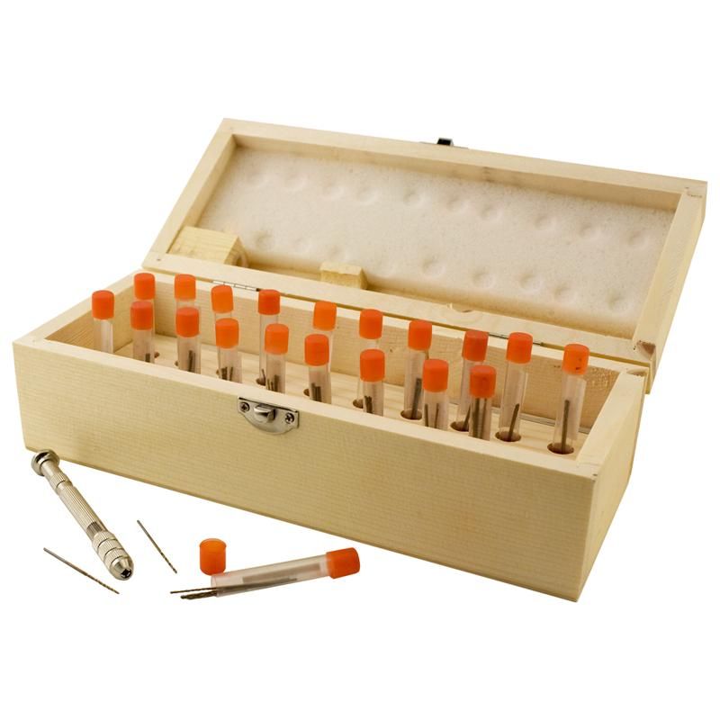
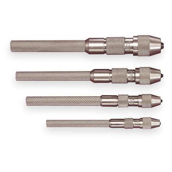
The boxed set also contains what appears to be a decent pin vise to go with them. These small bits won't survive use in a high speed rotary tool, so you'll get a lot of use out of the pin vise which has four collet chucks inside it to properly hold the full range of bit sizes in the set. (Or you can spend a few bucks more and treat yourself to a nice set of top of the line Starrett pin vises.
Starrett Pin Vise Set, 0.010-0.200, Taper, 4Pc S240Z | Zoro
- Canute, thibaultron, Stevinne and 3 others
-
6
-
5 hours ago, NavyShooter said:
For $1500, you can get a Grizzly 8x16" lathe - 8" x 16" Variable-Speed Benchtop Lathe at Grizzly.com
That's less than $200 more than the biggest Sherline mini lathe, with a heck of a lot more capability.
To be honest, if you've got the space for a Sherline, you've got the space for the Grizzly, and it's a heck of a lot more machine.
There's much wisdom, experience, and good advice in what NavyShooter has posted.
Buy the best you can. The most expensive tool is always the one you have to buy twice.
- NavyShooter, Knocklouder, Canute and 2 others
-
5
-
Good precision machine tools, well cared for, should be capable of being handed down for as much as a couple of generations, if not more and be expected to hold their value well in what has otherwise become our disposable culture.
1. How much money are you planning to save?
2. How much money can you save between now and when you croak?
3. What do you want to do with this lathe? (e.g.: maximum workpiece size, primary materials worked, primary type of work anticipated.)
Number 3. above will determine which lathe and tooling would best suit your needs. With this information, I'm sure you'll have folks from every camp able to give you the particulars matching your requirements.
Today, there are probably only three options for small lathes useful for modeling:
1. The Chinese Sieg-made "seven by's" sold everywhere. Get a long bed version. Buy it from a top tier vendor (e.g.: Little Machine Shop, Grizzly) Who you buy it from is important because the Sieg, the Chinese manufacturer, sells the exact same models to retailers, but with varying levels of quality control. You get what you pay for. At the bottom end, you may buy a lathe that will not even run accurately without a total rebuild.
2. The Taig mini-lathe, a high-quality precision machine, but somewhat smaller and lighter than the Sieg's.
3. The Sherline models, like Taig, but perhaps with somewhat greater versatility in terms of available tooling.
There are a few other options out there, but it's important to make sure that tooling is available at a reasonable cost. The now-discontinued and legendary EMCO Unimat SL/DB and Unimat 3 lathes, were amazing modeling mini-lathes which could be, with the attachments, turned into all sorts of machines such as a milling machine, a scroll saw, a table saw, disk sander, and so on. You will see many on eBay and lots of parts availability from "parted out" machines, but many of the machines need to be rebuilt and/or require tooling which is extremely expensive. If someone gives you one in good shape with all the attachments and tooling, grab it. Otherwise, walk the other way. These are seductive little machines, but, sadly, they are no longer made and so any parts or tooling you may ever need will have to be sourced on the recycled parts market at premium prices. (There is a currently produced line of "Unimat" lathes which are not the same thing as the originals at all. Another example of somebody buying the name and slapping it on an inferior product.) Another option may be to acquire a fine watchmaker's lathe. These are often beautiful works of art in and of themselves, but expensive and the tooling is very expensive, so beware. Some of these lathes use odd-ball fastener threadings and you'll pay hell to find tooling that will fit on them. One of the early decisions you will have to make is whether you want a lathe that is scaled in metric or imperial measurements. They go downhill in standardization from there and few tooling parts are interchangeable between the various makes and models.
In most cases, the tooling to complete the average range of the basic machinist's work on any given lathe can easily run as much again as the base purchase price of the lathe and that applies only to lathes that are currently in production. Once a particular lathe is no longer produced, its lifespan is limited to the first essential part that breaks and cannot be replaced. Well, not exactly. Any part can be reproduced, but it can easily become more costly to do so than to unload the machine and start anew, but that could mean abandoning thousands of dollars invested in proprietary tooling collected over the life of the dead machine.
Buy the best you can possibly afford and then some. (It may be necessary to jettison excess expenses, e.g. pets, wives, children, though not necessarily in any particular order. Be brave. Be strong. Be ruthless.)
Buy the largest you can possibly afford and/or for which you have room in your shop. There will always come a day when you find yourself with a job too big for your lathe. Better later than sooner.
Often, the best option is to buy a used lathe, but if, and only if, it's a model with easily sourced and reasonably priced parts and tooling which hasn't been ruined by misuse or worn out. (A used lathe should always be examined by a knowledgeable person before purchasing.) It may pay to read the local obituaries. If you can find a machinist's widow who wants to get the garage cleaned out, you may find the Holy Grail!
- NavyShooter, mtaylor and Canute
-
3
-
Jaager's right. Anybody doing any amount of woodworking beyond stick framing carpentry needs to have, or have access to, their own milling equipment. Only then is the price of wood anywhere near reasonable. (Even rough sawn wood at the lumberyard is much less expensive than finished four sides.) With a bandsaw and a thickness planer, you are good to go and you'll discover there are lots of sources of wood, particularly recycled wood. Make friends with somebody who's got the tools to do the job.
For bread and butter lifts, look for clear pine shelving at the big box stores. You can probably find nominal 1"x8"x48" pretty easily. Be creative. Look around. If you have to, sort through the piles of fence boards until you find some good clear ones, or ones with knots that you can work around. If you can find a pallet or two with wood that's easy enough to work, You should have no problem disassembling a pallet and getting wood for a bread and butter hull. (Keep in mind, oak may be too tough to whittle easily.) While used furniture is usually too nice to use for bread and butter lifts, it can be a good source of modeling wood. I've got a couple of leaves from old dining room tables I found at the dumps that look to be fine old mahogany like you can't get anymore. I suppose I'll find a use for it one of these days. I also have a 2"x6"x8 foot piece of old Burmese teak in my wood stash. I snagged that from the boatyard dumpster. My wife asks why I have all this old wood stored in my workshop. She just doesn't get it.
-
2 hours ago, Jaager said:
With wooden ship models of vessels before 1860, the difference in weight that being hollow produces seems like it would not be significant.
I don't think it would be significant in that case, either. We must remember, though, that the USN specs for ship models were designed (and later written) for ship models of WWII vintage and newer, so six foot long models weren't all that unusual. A modern-day aircraft carrier at 1:96 would run around ten and a half feet long.
I must confess that after checking it, I discovered my recollection of the USN model mil specs was "bass ackwards." They prohibit gluing the two halves of lifts cut together at the ends in models of less than 12" maximum beam! They only require hollowed lifts for models with more than a 12" beam. They say that on hulls of less than 12" maximum beam they require that "...hull lifts shall be cut to the full body shape; lifts shall not be cut in halves, thereby creating a glue seam along the vertical centerline of the model." This would suggest that hollowed lifts were at the builder's option in hulls with less than a 12" maximum beam as long as the lifts were built of a solid piece of wood, and mandatory for hull's with a greater than 12" maximum beam and hulls over a 12" maximum beam could be glued up of two pieces along the centerline. That would tend to make sense because mahogany or basswood lift stock wider than 12" isn't all that easy to come by. All and all, ship modelers would do well to aspire to following the Navy's specifications.
Actual text of USN ship model contract specifications:
Hull
Hulls shall be built up in lifts of clear, first-grade mahogany or basswood; doweled and glued together with water-resistant glue. The wood shall be completely free of knots, checks, and sap pockets and shall be thoroughly seasoned. Models over 12 inches beam must be hollowed for reduction of weight The hull shall be composed of the least number of parts necessary to achieve the proper shape. An excessive number of glue joints shall be avoided. On models less than 12 inches beam, hull lifts shall be cut to the full body shape: lifts shall not be cut in halves, thereby creating a glue seam along the vertical centerline of the model. The lifts shall conform accurately to lines of the vessel as shown by the plans. A stable, durable, flexible body putty may be used in moderation to fill gaps.
-
12 hours ago, Jaager said:
For those of us who build wooden sailing ships, the plans come with WL. Rather than doing any lofting, the WL from the plans determine the lift thickness.
The hollow insides are a requirement from the USN museum.
Very true. The poster intends to build a radio controlled model, so he'll have to open up the inside. I think the USN's model standards require hollowed bread and butter hulls because this makes the model much less heavy and they do a fair amount of moving their models around. The USN's ship model "mil specs" also require lifts be in two pieces, one to each side and glued together down the centerline (being cut two at a time as described in my previous post.) I believe this is required because of the propensity of a single plank splitting along the grain at the "pointy ends" of the center cut-out, but I'm not sure I understand exactly why that would be any different than a glue joint. I suppose the glue joint done properly would be stronger than a narrow section of grain alone.
If the plans show the waterlines, there's no reason not to use those, but if the body section plans are available without the waterlines superimposed, or if one wanted to set the thickness of their lifts themselves, it's an easy thing to line off your own waterlines on top of the body sections and take off the distances at each body section station for each waterline.
-
1 hour ago, Riotvan88 said:
I do appreciate the advice, just out of interest how thick would the lifts be for a typical bread and butter build? Wouldn't it require a huge amount of shaping and sanding to go from a blocky form to the final smooth hull form unless one made many thin lifts?
The thickness of the lifts are up to the builder. The thicker they are, the more you have to shave off to fair the hull. In a hull like you are contemplating, though, there'd be a lot of flat areas amidships that wouldn't need much fairing at all, which would tend to favor thicker lifts. It's really a question of the size of the hull and how "curvey" it is. Bread and butter construction is more common in larger models. Inch thick lifts would probably work fine on a three or four foot hull. Half-inch lifts would be fine, too, well, but with twice the work to saw them out... and half the work of fairing, more or less. The way they are often made is to only loft the waterline shape from the centerline and use that for a pattern. Two identical halves of a lift are cut out at once from two planks stacked one on top of the other. (These are often screwed together to keep them from moving when the sawing is done.) The "inside" is also cut out of the stacked planks. The pieces are then separated and one turned over and the two glued together at the bow and stern. The result is one whole waterline lift for half the sawing work and the certainty that both sides of the lifts on each side of the hull are identical. The lifts are often cut a bit wide of the line at the bow so the vee of the bow can be faired exactly to the centerline without the risk of over-doing it by accident. If the corners of the lifts that define the shape of the hull are marked with a felt tipped pen or the like, all you do is remove the lift edge that's standing proud and use the black marking to guide you down to as far as the excess needs to be faired. That can be done with a chisel. a spokeshave, or even a pocket knife. When you get close to removing all the excess wood from the lifts, you take a flexible batten with sandpaper glued to it and, bending it to conform to the shape of the hull, sand in all directions to complete the fairing process down to the glue lines marked by the black felt tipped pen ink.
-
There's a ton of information on line about model steam launches. Check out these websites: building a model steam launch - Search (bing.com) and these YouTube videos: building a model steam launch - YouTube
Running the engine on compressed air is a good indication that it will run on steam. At least it's not frozen. Still, the valve may have to be adjusted so it runs smoothly on steam.
Parts are readily available online. You can get safety valves, feedwater pumps, plumbing stock, water glasses, pressure gauges, shafting, and propellers, and such mail order. (Steam propellers have a much greater pitch and turn at lower RPMs. Steam engines have tons of torque. Internal combustion engines have lots of speed and poor torque compared to steam, so the pitch of their propellers is much less. The steam prop takes big slow bites. The IC engine prop takes fast small bites.) Google is your friend. As you probably know, there are dedicated live steam model forums and a lot of live steam hobbyists on the R/C forums. All the live steaming models are run by radio control these days. Ages of Sail, in the San Francisco Bay Area, is a mail order and brick and mortar ship modeling shop and a sponsor of this forum. They have a U.S. distributorship for Saito model live steam plants, live steam ship model kits, and related R/C gear. You can get anything you need in terms of parts from them... for a price. Ages of Sail also carry kits for live steam launches, tug boats, and so on. See: Saito Manufacturing - Steam Engines and RC Kits (agesofsail.com)
I'm familiar with gasoline boiler burners. at least those that heat a coiled copper tubing water tube "flash boiler" that surrounds the burner. These were popular a hundred years ago. They usually surrounded the water tube coil with refractory material and asbestos lagging compound. The burner was an old-time converted gasoline blow torch burner. They scared the heck out of me. I'd definitely go for a modern commercially made boiler that runs on propane from a stock propane torch bottle. Save the old gasoline burner as an antique, but don't try to run it if you don't want to end up like Richard Pryor did with his crack pipe! You may be able to use the boiler you have and install an updated propane burner in it. Hydrotesting a small model launch boiler is a no-brainer if you have a pressure gauge on it and a compressor. Boiler pressure is quite low and if you use a water tube boiler, if it blows, the water in the tubes squirts out all over the place and puts your fire out and it's just a mess to clean up as opposed to a bomb throwing shrapnel all over.
You may be familiar with Main Steam Models in England. Lots of eye-candy on their site. Mainsteam Models | Live Steam Engines | Model Engineering Tutorials They have a Patreon video series on "How to build a model live steam launch."
A couple of Stuart 10V plants with different boilers. The first is gas fired.

From: Mainsteam Models Gallery | Steam Engine | Tutorials | Help & Info
The rest of the photos are of a coal fired plant!


This multi-part YouTube video series will keep you busy for a while. The guy knows his such.
-
3 hours ago, Riotvan88 said:
Thanks for the advice. I do have some experience and not a total beginner. I've built a Billings smit Rotterdam. Along with a couple of caldercaft models and a scratch built albeit basic model I built some years ago. For the Rotterdam I replaced most of the fittings with ones I made. So creating the detail parts is no problem.
What I'm mostly asking here is what wood is best for the moulds/bulkhead. I've no idea what is used in kits but they didn't involve doubles with joints. Which is why I'm asking simply because whatever wood the kits use seemingly allows one to eliminate that process. I don't want to incur unessesary expense on fine decorative wood and don't want something that isn't up to the task. So hopfully that explains why I'm asking these questions.
I've not been very clear but the plans I have are complete, what I meant by more work was that to do a bread and butter method I'd have to measure each cross section at various heights and record that data to create the waterlines either in drawing form or a list of points to work from. Otherwise I can just cut directly from my plans as is.
The reason I don't want to buy the kit is because it is 1/100 and I want this to be 1/75 and I want to scratch build it.
Okay, I've got it. I won't pester you further to go the "bread and butter" route, except to add to what I've said before that buying pine, poplar or the like for a "bread and butter" hull is a lot less expensive than buying pre-milled wood for frames and planking and even considering the time you might take to loft the waterline shapes, it's would be much faster and easier than building the hull plank on frame where you will have to cut out all those individual frames, etc. You're drinking it, though, not me, so pick your poison.
-
22 hours ago, Bob Cleek said:
It appears to be a main staysail. This sail is a fore-and-aft rigged sail attached to the main-mast. It's the same as a mizzen staysail, but on the mainmast.
22 hours ago, Martes said:It's kind of two times larger than regular main staysails, and is fixed not to the mainmast, but to main topmast.
Correction: "Main topmast staysail." It's a headsail with its head attached to the mast and its luff attached to the stay attached to the head of that mast.
The general sail naming convention is to first state the mast the sail is hoisted on and then the type of sail it is. This one, being attached to the stay, is a staysail. Beyond that, they come in all different sizes like any headsail and can be named whatever the captain wants, e.g.: "the big main topmast staysail," or the "main topmast genoa," and so on. In some instances, unusual sails acquire odd-ball names that become so popular that they endure, such as the "gollywobbler," a twin-headed light air reaching sail set flying from the fore and main mastheads of a two-masted schooner.
-
8 hours ago, Riotvan88 said:
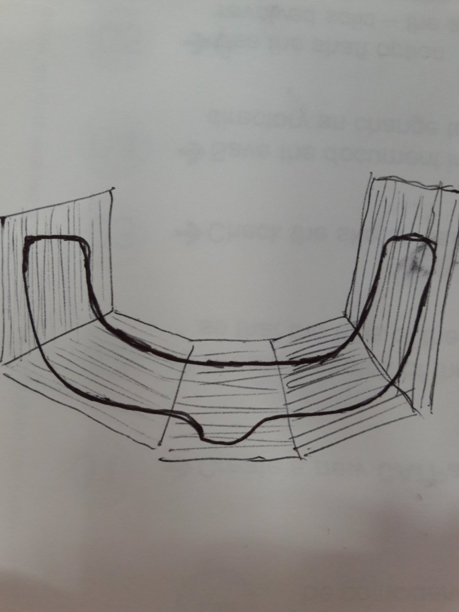
Ok thanks again. My understanding is that I need to create a frame from pieces arranged such that the grain does not run out at the outside edges where the planks will attach. Something like the image attached? And done in pairs with the joints overlapping.
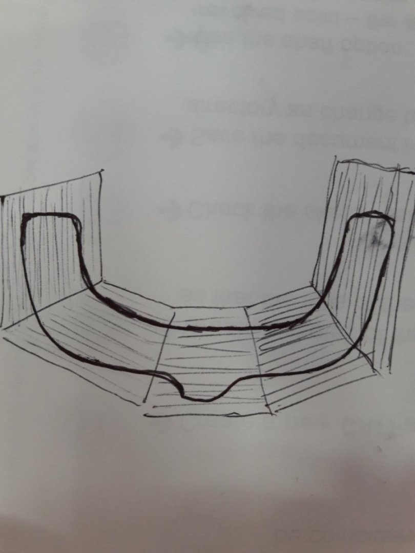
You got it! You can double the frames or you can join the pieces end to end with half-lap joints.
Which is why I suggested you build your hull using the "bread and butter" lift method like the majority of working ship model builders do when building a one-off wooden hull, especially for R/C use.
From the questions you've been asking, it seems that you may presently lack the breadth of experience and understanding to be attempting to scratch-build an R/C model from plans that by, your description only provide data, on decks and frames. This isn't intended to be a criticism nor to discouraging from building a model ship at all. It's just that a steep flight of stairs isn't the best place to learn to walk. Even with greater experience and skill, you aren't going to get far with incomplete and inadequate plans. I suggest that you consider buying the Billings Boats (kit company) Zwarte Zee tug model kit. (I've never been a fan of Billings Boats kits, but that's just my personal opinion. Others appear quite satisfied with them.) Billing Boats Zwarte Zee B592 Model Boat Kit | Cornwall Model Boats (I'm not sure, but Billing may have updated their Zwarte Zee kit from a wood hull to a plastic one.) You will get everything you need in the kit (less the R/C running gear, I expect) and, clearly, if you are having problems deciding which wood to use at this point, you have no idea how much trouble you will encounter trying to source other parts for your build (unless you are going to start turning your own from raw brass and copper and soldering the parts together.) You can get the parts from Billings, of course, but it would likely be very little more money to buy the whole kit than the parts piecemeal and you'd be getting the wood, a complete set of plans, and a set of instructions. As is turns out, Popeye the Sailor of this forum is just commencing a build of the Billings Zwarte Zee tug kit. You can look over his shoulder and learn a lot as he progresses:
-
-
1 hour ago, Riotvan88 said:
Thanks again. Is there any wood type that would allow the whole frame to be cut without doing them in pieces? If I remember correctly the kits I've done were cut in single pieces?
All wood has grain, so the problem of grain run-out on curved shapes is always an inherent weakness. There are some woods that have what is known as interlocked grain and for that reason are less prone to breaking along the grain, but such woods are difficult to work and generally not suitable for modeling work. I'd expect that the kits you are recalling had frames or bulkheads cut from plywood. Plywood doesn't have grain run-out problems because the plies are laminated with the grain running at right angles to each other. The main problem with plywood bulkheads and frames is that the edges of plywood don't take adhesives or mechanical fasteners well at all which causes major headaches when trying to fasten plank to them.
Boston Whitehall Tender by mjcurtis - FINISHED - Model Shipways - 1:14 (7/8"=1') - first build
in - Kit build logs for subjects built from 1901 - Present Day
Posted · Edited by Bob Cleek
There isn't any such thing as a "slight clinker effect." Plank is either hung "carvel" or "clinker" (AKA "lapstrake.") You did well to follow your instincts when planking and taper your planks. In fact, your intuitive solution is quite close to the actual practice, determining the width of the plank at the frame at the greatest beam and then the proportionate width of each plank at every other frame, which will give you the shape of each plank when the dimensions are laid out and a batten is sprung between the points so generated.
If a hull is to be carvel planked, the edges of the planks are butted against each other and the hull is "faired," being planed and sanded to a fair shape so that a perfectly smooth hull results. A carvel planked hull is caulked with oakum and/or cotton driven between the plank edges so that the swelling of the planks against the caulking produces the necessary watertightness.) If a hull is to be clinker built, the planks are cut wider so that their edges overlap the adjacent plank, with the overlapping edges planed to a bevel which permits to overlapping planks to be riveted together, pulling the faying surface tightly together. (In this method, the swelling of the lapped plank faces provides the watertightness.) A clinker planked hull will have "gains" cut in lts plank ends so that the overlap transitions to a flat surface at the stem (and sometimes to some degree at the stern.). These gains are sloping rabets that reduce the thickness of the plank at the end overlap.
"Strip planking" is a relatively new technique made possible by epoxy adhesive technology. In this method, "strips" generally as wide as they are thick, are "stacked" up and glued with epoxy adhesive, then sheathed in fabric and resin. They are a form of monocoque construction, without frames. They can be quite attractive, but are not historically correct as far as their construction goes.
Google "Whitehall pulling boat" images and you'll see the range of "Whitehall" styles planked both types. Some examples are below.
Your kit apparently was designed to be simply "strip planked" (after a fashion) and finished to appear as a carvel planked example of the type. A clinker planked Whitehall at the scale you are working with would be a much more involved planking exercise than would be a "carvel-looking" hull. I would suggest you finish the hull smooth and painted inside and out so that it appears to be a carvel planked hull. It will not appear correct if it has "a slight clinker effect."
John Gardner's book Building Classic Small Craft, mentioned above, is an excellent resource for anyone building models of small craft. Indeed, with that book, one can spend a lot of time building many classic small boats without the need of kits at all.
A carvel planked Whitehall type pulling boat. Note that the hull is smooth inside and out.
An example of a couple of clinker planked pulling boats. Note the "gains" at the plank ends and the number of planks used. Note that the plank overlaps are visible both outboard and inboard with the sawn frames sometimes "jogged" with notches so the plank lies flat on the plank face and sometimes not, those frames being steamed.
An example of a strip planked Whitehall pulling boat. Note the large number of "strips" and the absence of frames.