Jump to content

Anchor Hoy c. 1825 by Maury S - FINISHED - 1:48 - Harbor craft - POF


Recommended Posts

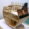
Working on the ceiling planks.  There are 12 strakes from limber to clamp.  Using a planking fan, three frames (12, 00 and E) are marked with tick strips (see the dim tick marks at far left and far right of photo) .  The taper is modest.  The three frame locations are marked on the plank, and a tick strip used to set the width.  A ships curve used to mark the taper on one side.  A  disk sander is used following the taper line, and fine adjustment is done by hand sanding.  The square hole on the port side (upper right) is to accommodate one of the bowsprit bitts.  The dark area on the frames is water from cleaning up the glue joint.  I have to get the clamps for the floor of the gear cabinet set properly before planking down from the main clamp.  That involves  measuring down from the bottom of the deck beams to allow for the height of the massive capstan gear  (more on that later).

Maury

post-923-0-30345800-1477665027.jpg

Link to comment
Share on other sites

Very nice and neat work there, Maury! Is the apparent wiggle in the deck clamps between about Stations 3 to 6 an optical illusion?

Be sure to sign up for an epic Nelson/Trafalgar project if you would like to see it made into a TV series  http://trafalgar.tv

Link to comment
Share on other sites

Druxey,

THANKS for pointing out the wiggle.  I laid a batten across the clamp and found it a bit low at frames 2 and three.  Back to the ISO.  Thank goodness for a camera lens and a fresh set of eyes!


I worked on the clamps for the gear deck.  I need 14.5" clearance below the lowest bottom of the deck beams for the gear, bearings and floor of the gear deck.  Frame #5 is the lowest in the area of the gear.  A 15" pattern block was held under a temporary deck beam at Fr. #5 to establish the top of the gear deck  beam (bottom of the floor) at this place.  The gear has to be parallel to the top of the keelson (not the main deck).  A measuring stick was held at frame #5 (see first picture)  and the height from the building board was marked and then transferred to the other side and to both sides of frame #12 (the farthest extent of the gears).  Putting the top of the gear deck clamps on these marks assures it is parallel to the keelson.   The clamp was held in place on both sides, temporary beams laid across the and a wide, flat piece (it's the bottom of the water tank) was laid over the beams to check level and flat.  Then the temp. floor and beams were removed.   Before the clamp was glued in place, the upper edge was eased in a rolling manner from front to back so the beams would rest on a flat surface, not just the corner of the edge.  I'll run a long sanding stick across the tops of the clamp (side to side) where the beams lay before final install.  Notice in the third photo how much difference (from level)  there is between the main deck clamp and gear deck clamp.  Now I'm sure the capstan axle will be perpendicular to the keelson.


post-923-0-62248400-1477752290.jpg

post-923-0-66910200-1477752729.jpg

post-923-0-26452100-1477753061.jpg

Link to comment
Share on other sites

More time spent on the interior planking.  Several strakes from bottom up and two top-down at the forward section.  Special treatment will be necessary around the gear-deck clamps.  Most of this work will be covered up but you all and I know it's there.  (please notice I did not use the term "y'all").

Maury


post-923-0-71692900-1477919536.jpg

Link to comment
Share on other sites

Love those little clamps.


Bob

Every build is a learning experience.


Current build:  SS_ Mariefred


Completed builds:  US Coast Guard Pequot   Friendship-sloop,  Schooner Lettie-G.-Howard,   Spray,   Grand-Banks-dory

                                                a gaff rigged yawl,  HOGA (YT-146),  Int'l Dragon Class II,   Two Edwardian Launches 


In the Gallery:   Catboat,   International-Dragon-Class,   Spray

Link to comment
Share on other sites

Maury, and you have evidence with pictures that it's there. Love those clamps too.

Just like your Emma C this looks amazing.


Please, visit our Facebook page!


Respectfully


Per aka Dr. Per@Therapy for Shipaholics 
593661798_Keepitreal-small.jpg.f8a2526a43b30479d4c1ffcf8b37175a.jpg

Finished: T37, BB Marie Jeanne - located on a shelf in Sweden, 18th Century Longboat, Winchelsea Capstan

Current: America by Constructo, Solö Ruff, USS Syren by MS, Bluenose by MS

Viking funeral: Harley almost a Harvey

Nautical Research Guild Member - 'Taint a hobby if you gotta hurry

Link to comment
Share on other sites

Druxey, I was going to put a molding piece over the ends of the "hanging planks" rather than cut them back to the earlier frames.  Frankly I never thought of cutting them back.  Would that be the way they were done?  Leaving a gap to the next frame?

Bob & Dr. Per, The little clamps are cut-apart planking clamps I bought from Modelshipways years ago and found useless as they were originally designed.

Link to comment
Share on other sites

Some revisions to the plans.  I checked prints of grossly similar boats of the same era on the Royal Museums of Greenwich (the old National Maritime Museum) site for layout of knees.  I only found one applicable print out of about fifty links.   It seems the pattern is as follows:  Forward of deadflat, hanging knees are attached to the fore face of the beams and lodging knees on the aft face;  aft the deadflat, the pattern is reversed.  Since there was only one print, I do not know if the pattern was standard.  Pdf file of the Hoy beam-plan is attached.  There are a few spots (around the mast and capstans) where there are mirrored lodging knees and no hanging knees. 

Maury

AH_DeckBeams2.pdf

post-923-0-18268700-1478626293_thumb.jpg

Link to comment
Share on other sites

It was part of the search for "Lighter" and the only one I found with knees visible.

Maury  It does look to be a larger ship.  If the dark areas on the edges are gunports, then it's clearly not a service boat.

M

Edited by Maurys
Link to comment
Share on other sites

Plans for smaller vessels rarely if ever showed knees. I would use a rule of thumb for the athwartship arms of the lodging knees and make them about 1/6th the length of the midship beams. That deck plan you posted is of the 90-gun ship Impregnable - not the best choice for comparison!

Be sure to sign up for an epic Nelson/Trafalgar project if you would like to see it made into a TV series  http://trafalgar.tv

Link to comment
Share on other sites

Druxey, Thank you.  Yedlinsky gives scantlings for knees of various decks and boat size.  For the upper deck, 5" sided and about 3' for the athwartship arm (for a or cutter...no hanging knee shown for a 300 ton sloop) . That would be close to your suggestion of 1/6th beam length.  A bit longer for hanging arm on hanging knees.  "Beams to be kneed at each end with 1 hanging and 1 lodging knee".  Do you think the same standard (Lodging and hanging knees at all beams) applied to a sturdy "work boat"?   

Maury

Edited by Maurys
Link to comment
Share on other sites

I suspect so, except they might be beefier around a large main hatch. These provide integrity between the deck and sides of a vessel and keep it all together.

Be sure to sign up for an epic Nelson/Trafalgar project if you would like to see it made into a TV series  http://trafalgar.tv

Link to comment
Share on other sites

  • 2 weeks later...

Slow progress over the last two weeks with other obligations.  Working on the balance of the ceilings up to the main deck clamps.  While waiting for paint (clear coat) and glue to dry I've found diversions in the water tank, the floors of the forward hold and lining up the correct heights of the bowsprit bits and the great cat bits.  The cat was assembled earlier. The sheave is two small brass washers.


post-923-0-30651800-1479572156.jpgpost-923-0-72716800-1479572172.jpg


The floor will sit on two of the forward half frames and will eventually be in two levels, side to side.  It's holly and may be painted or stained later.


post-923-0-46808300-1479572394.jpg


Then came the lining up of the bitts.  I cut and sanded two test beams to the molded and sided measurements.  The height of the bowsprit bitts above the deck is specified and they anchor on the frame.  The cat bitts extend from the side of the keelson to the bottom of the deck beam just forward of the mast.  The beam needs to align there and allow room for the great cat to pass through the deck.


post-923-0-54413700-1479572747.jpgpost-923-0-11784500-1479572766.jpg

Maury


Link to comment
Share on other sites

It's been a busy day.  The water tank is almost done.  It probably had a top.  I'll put a few planks  to illustrate.  It needs a (left to right) divider at the end and another (top to bottom of pic.) closer to the front to provide four separate sections.  The tanks of the era were of cedar.  I used some scrap cherry to get a different color.  It's going to be called red cedar.  There is a well in the middle of the tank protecting the axle of the fore capstan.  It has one side cut-out for display.


post-923-0-31766500-1479594646.jpg


More test fitting of parts...I've been holding this back for several months.  One of the features that attracted me to this boat was the gearing of the capstans.  Chuck Passaro made the gears for me on his laser cutter.  There are beads on the under side to represent ball bearings.  They will fit on a "race" on top of the gear deck floor.


post-923-0-65702000-1479595015.jpg


post-923-0-95937700-1479595032.jpg


There will be enough room between the bottom of the beam and the top of the gear.  Careful planning.

Maury

Link to comment
Share on other sites

Great looking water tank, Maury.  And that gear set is something else.   How big is that main gear?

Mark
"The shipwright is slow, but the wood is patient." - me

Current Build:                                                                                             
Past Builds:
 La Belle Poule 1765 - French Frigate from ANCRE plans - ON HOLD           Triton Cross-Section   

 NRG Hallf Hull Planking Kit                                                                            HMS Sphinx 1775 - Vanguard Models - 1:64               


Non-Ship Model:                                                                                         On hold, maybe forever:           

CH-53 Sikorsky - 1:48 - Revell - Completed                                                   Licorne - 1755 from Hahn Plans (Scratch) Version 2.0 (Abandoned)         


Link to comment
Share on other sites

Mark, the large gear is 14' diameter and the ratio between the gears is 8:1.  The original Grice drawings show it a bit larger, but it would not have fit abeam at that size.

Maury

Link to comment
Share on other sites

Those gears look great.  I hope you are not planning on covering them up with too much planking.

Toni


Chairman Nautical Research Guild

Member Nautical Research and Model Society

Member Midwest Model Shipwrights


Current Builds:     Utrecht-1742

Completed Builds: Longboat - 1:48 scale       HMS Atalanta-1775 - 1:48 scale       Half Hull Planking Project      Capstan Project     Swallow 1779 - 1:48 scale      Echo Cross Section   NRG Rigging Project 

                           Utrecht-1742

Gallery:  Hannah - 1:36 scale.

Link to comment
Share on other sites

Thanks for the likes and comments.  Toni, laying out the gear deck and main deck planking to expose the gears is a primary goal.  I've sanded off some of the hard edges of the gear and it looks better...picture to follow.  I'm not sure, but I think that having the axles of the gears going down to and bedding at the keelson transfers some of the weight of the massive gear to lower in the hull.  Engineers out there feel free to chime in.

Maury

Link to comment
Share on other sites

Maury,


Yes and no. The vertical forces thansferred to the vessel's structure by the gear's weight are primarily resisted by the ball race but as this race is not rigid it would be expected to deflect and some of this load would have been transferred to the keelson.


The gear's effect on the center of gravity of the vessel's hull would be at the vertical height of a plane passing through its vertical centerline.


Are you sure that this gear was a one piece casting? It could have been built up from cast segments bolted together, cast iron segments bolted to a wooden spoked wheel, or it could have been entirely wooden like those seen in water mills.


Roger

Link to comment
Share on other sites

Roger, Thanks.  I have not way of knowing whether the gears were a solid casting.  The only thing we have is the Grice drawings (see first post on this log).  I doubt the gears were wooden with wear considerations, but built-up parts or metal gears on a wooden axle are certainly possible.  If anyone else has a information please add a comment.

Maury

Link to comment
Share on other sites

Maury, Yes, I agree that other then showing the basic gear train the Grice drawing does not provide the necessary details. In that case, I generally try to find out what the state of the art was at the period in question.


In this case, I believe that the technology was not available in the US to machine involute pattern gear teeth in a large iron wheel like this. On the other hand examples exist in England of large wooden gear trains in water mills. For example see www.whitemill.org. There is another example of an iron gear wheel with wooden teeth. The teeth were shaped from a hard wood like apple and were inserted into cavities cast in the iron wheel. This approach was favored as the teeth were the "weak link" that would fail first and could be easily replaced.


The famous marine engineer Benjamin Franklin Isherwood used a wooden gear train in the late 1860's (40 years later than your period) to increase revolutions of the main engines of the high speed cruiser USS Wampanoag. The gears supposedly wore 5/8in during the vessel's sea trial.


You are to be congratulated on building this model of a usual and unique craft. You are doing a great job.


Roger

Link to comment
Share on other sites

Roger,

Thank you for the comments.  This is invaluable information and I am so glad to have received it.  The link and pictures of the mill with the large wooden gears now have me leaning towards displaying it as such.  I would include one of the pictures, but do not want to step on the copyright.  See the link:   http://www.whitemill.org/z0012.htm


 It's just a matter of sanding the black paint off the pieces and simulating joints.  

I love this organization.  So much help from so many people.

Maury

Link to comment
Share on other sites

With special thanks to Roger, I re-worked the gears as built-up wooden gears.  The joints are simulated and the bolts are 20 pound mono- filament line.  The lighter parts in the center are a reflection of the light above...not a different color.  They are certainly more interesting this way.

Maury

post-923-0-71362600-1480107872.jpg

Edited by Maurys
Link to comment
Share on other sites

Join the conversation

You can post now and register later. If you have an account, sign in now to post with your account.

Guest
Reply to this topic...

×   Pasted as rich text.   Paste as plain text instead

  Only 75 emoji are allowed.

×   Your link has been automatically embedded.   Display as a link instead

×   Your previous content has been restored.   Clear editor

×   You cannot paste images directly. Upload or insert images from URL.

  • Recently Browsing   0 members

    • No registered users viewing this page.
×
×
  • Create New...