Search the Community
Showing results for tags 'Model Shipways'.
-
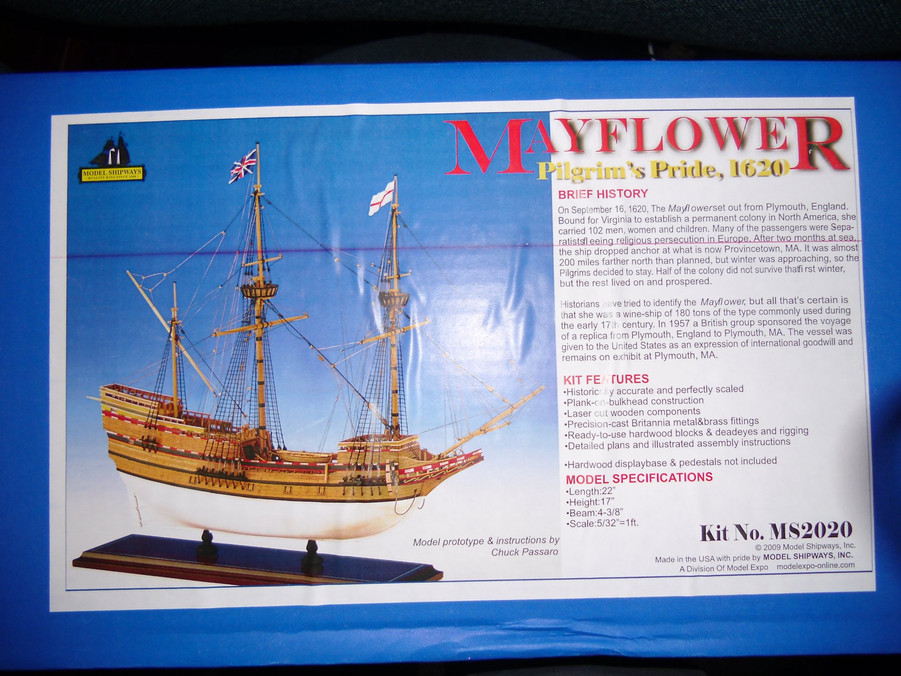
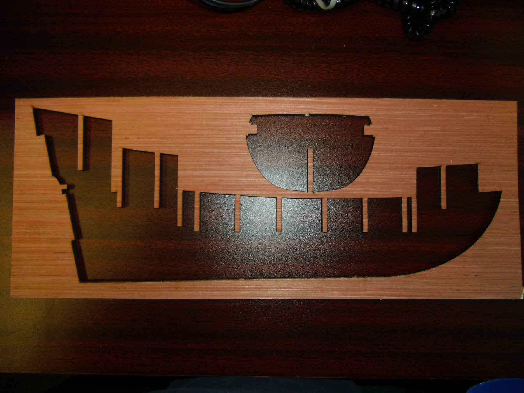
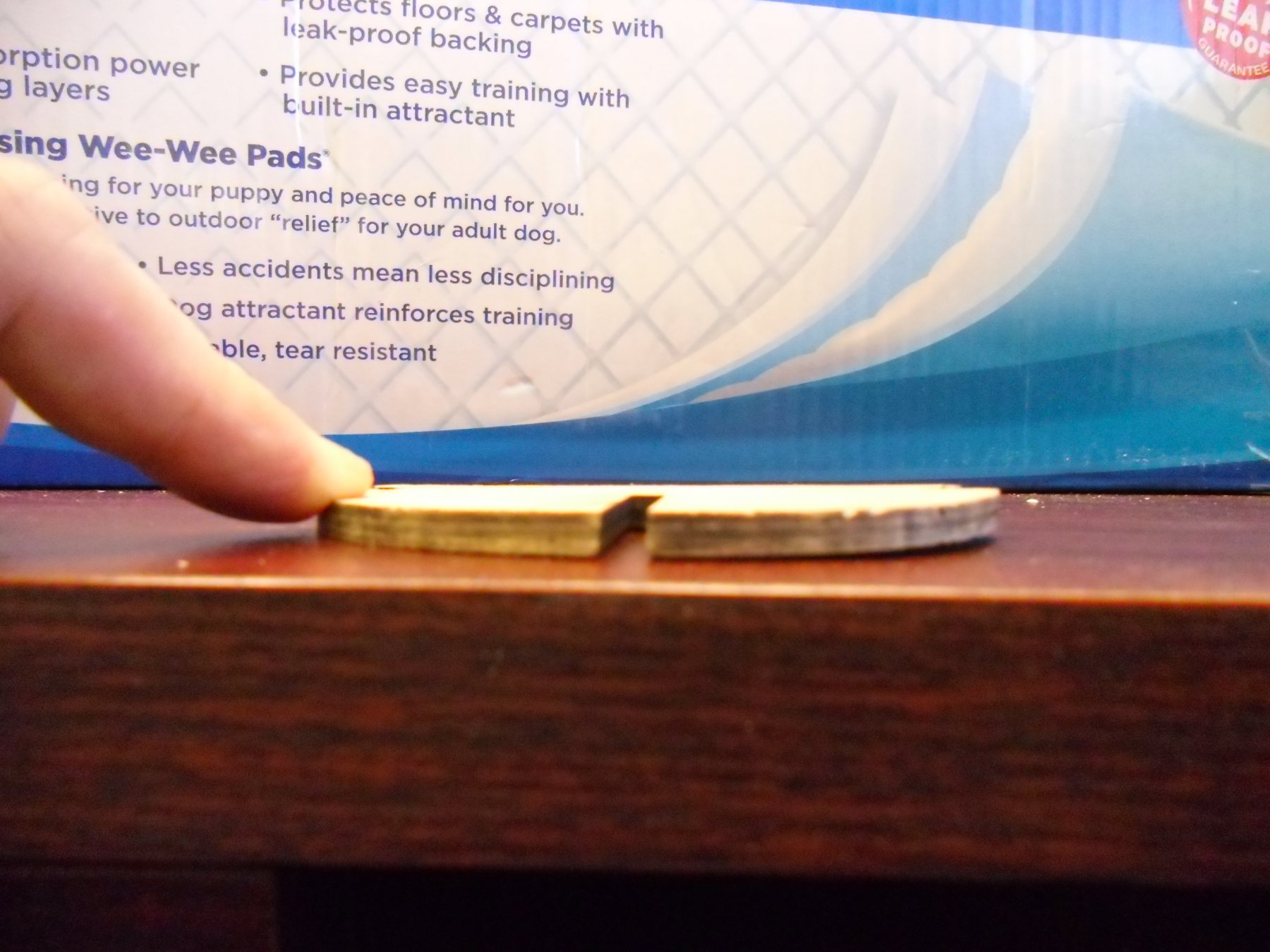
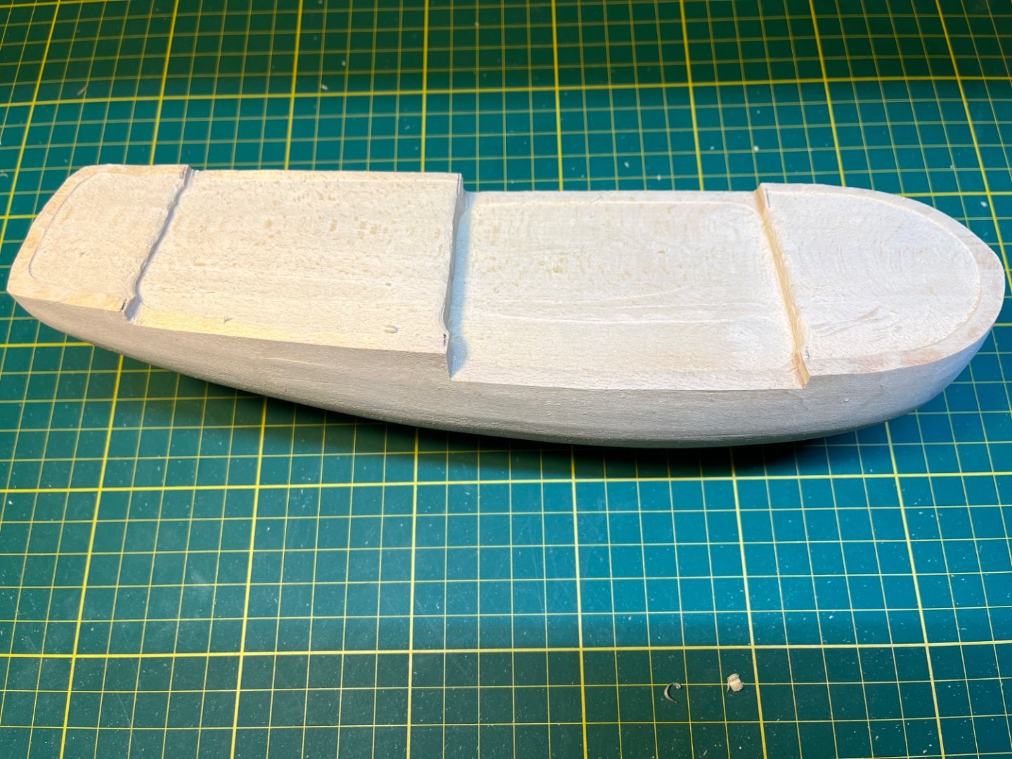
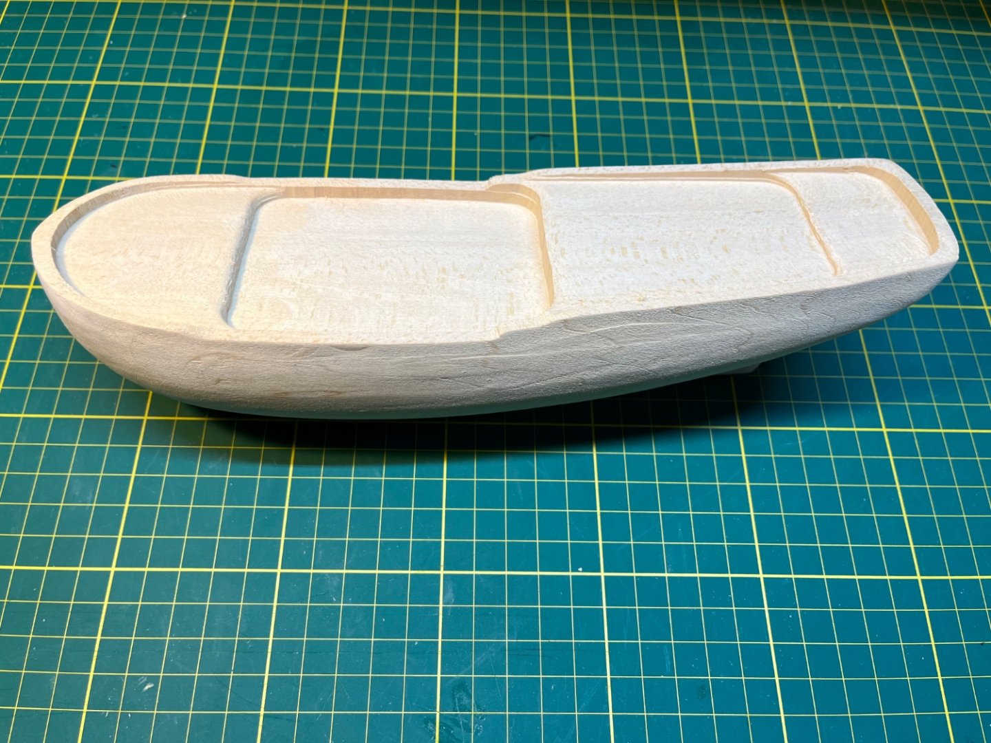
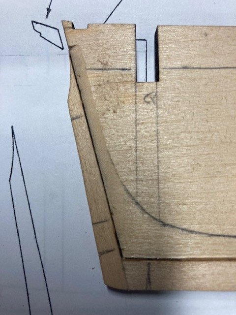
 I am moving on to this ship after finishing the NRG half hull planking project. I was looking for my next ship when I was finishing the MS Lobster Smack and found Chuck Passaro’s very detailed shop notes for this model. I kept looking at those instructions wondering if I could follow them. I finally decided to order the kit, but after about 6 weeks, Model Expo told me that they had stopped making it. So I did the half hull project next to work on my planking skills. While I was working on it I found a Sultana kit on EBay. I think it’s pretty old. The shop notes give detailed instructions for modifying the kit and doing some scratch building. Some parts of it look pretty difficult. I am especially worried about the fun with Sculpy parts that involve sculpting a new quarter badges and a figure head, but they are a long way off, and I can always wimp out and just use the cast ones that come with the kit. The hull is supposed be planked above the waterline, and the planking replaces the carved bulwarks so the first step is to modify the solid hull. This is the hull as it comes out of the box: This is after slowly shaving off the bulwarks. I am glad I bought a big pack of number 11 blades for this one.! I think there is more to take off, but decided to finalize it when the time comes to sand and shape the decks: I cut out the hull profile templates and started shaping the stern. It needs a lot of wood removed! Chuck recommend a rotary tool. I did that for a bit. It made quite a mess and made me nervous I was going to take off too much wood. I switched to sand paper wrapped around a dowel to take away more wood for the concave curve at the stern. The profile template says there is more to take off. This is my first solid hull model, and I think the challenge is going to be using the templates to get the hull shape correct. I seem to work pretty slowly, and I think this one is going to take me a quite while!
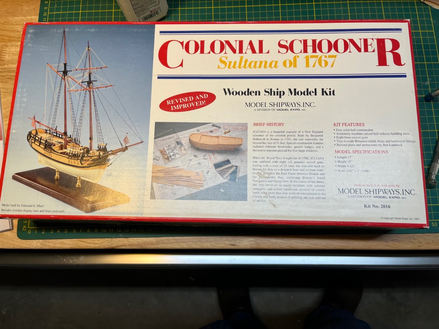
-
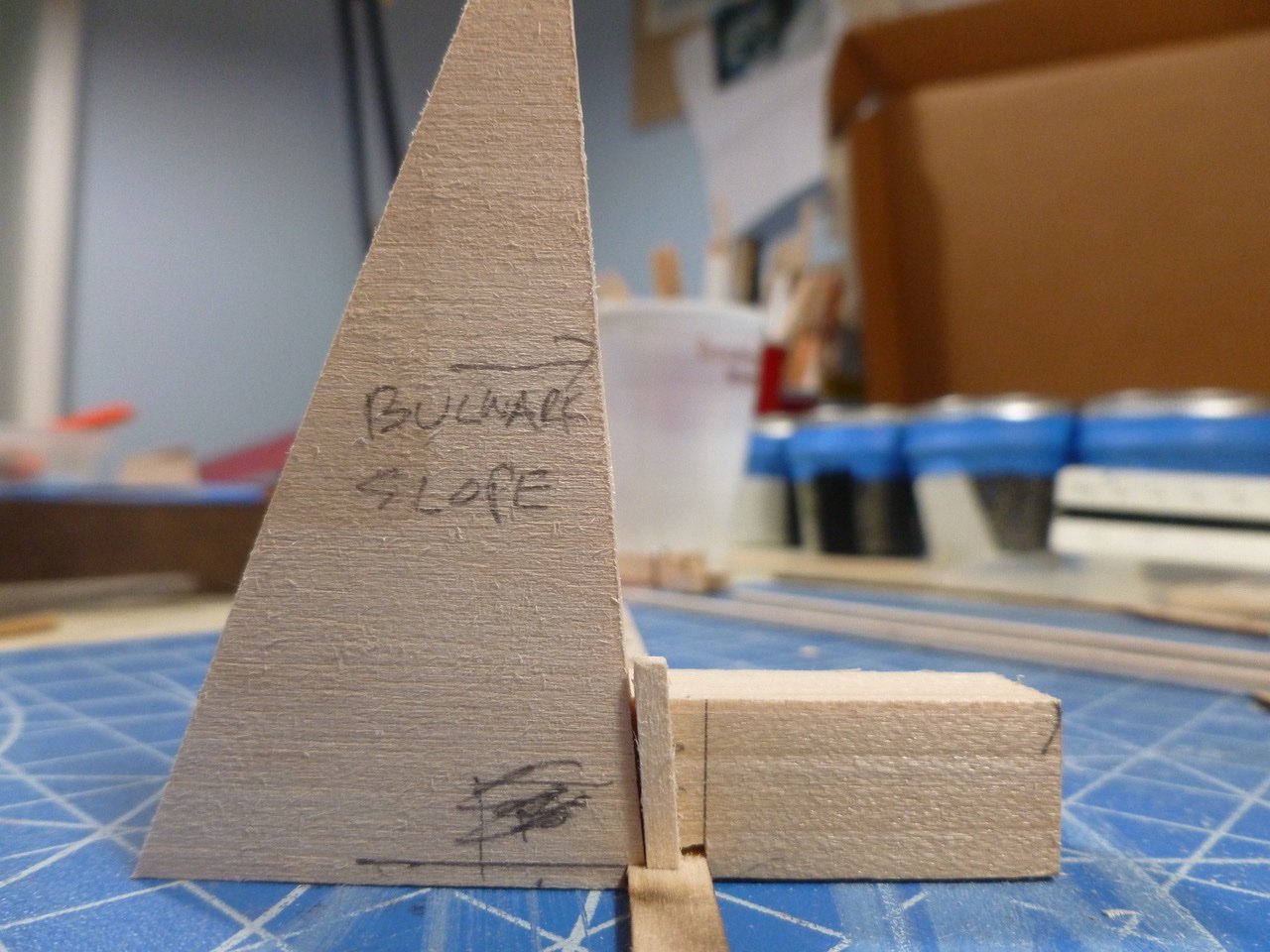
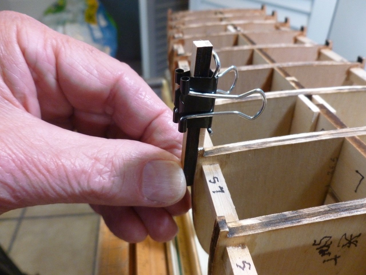
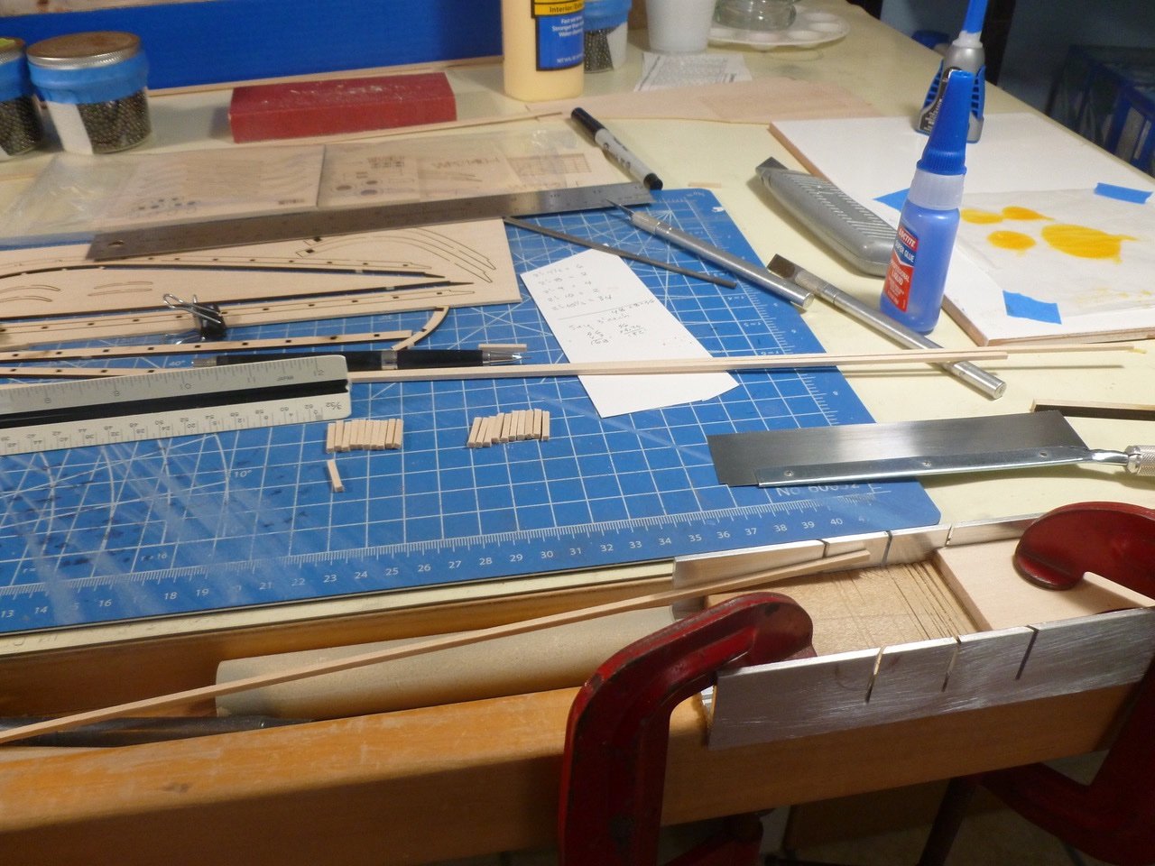
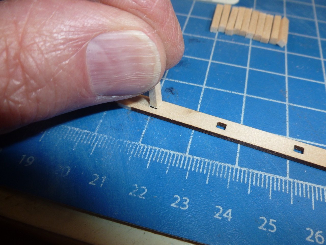
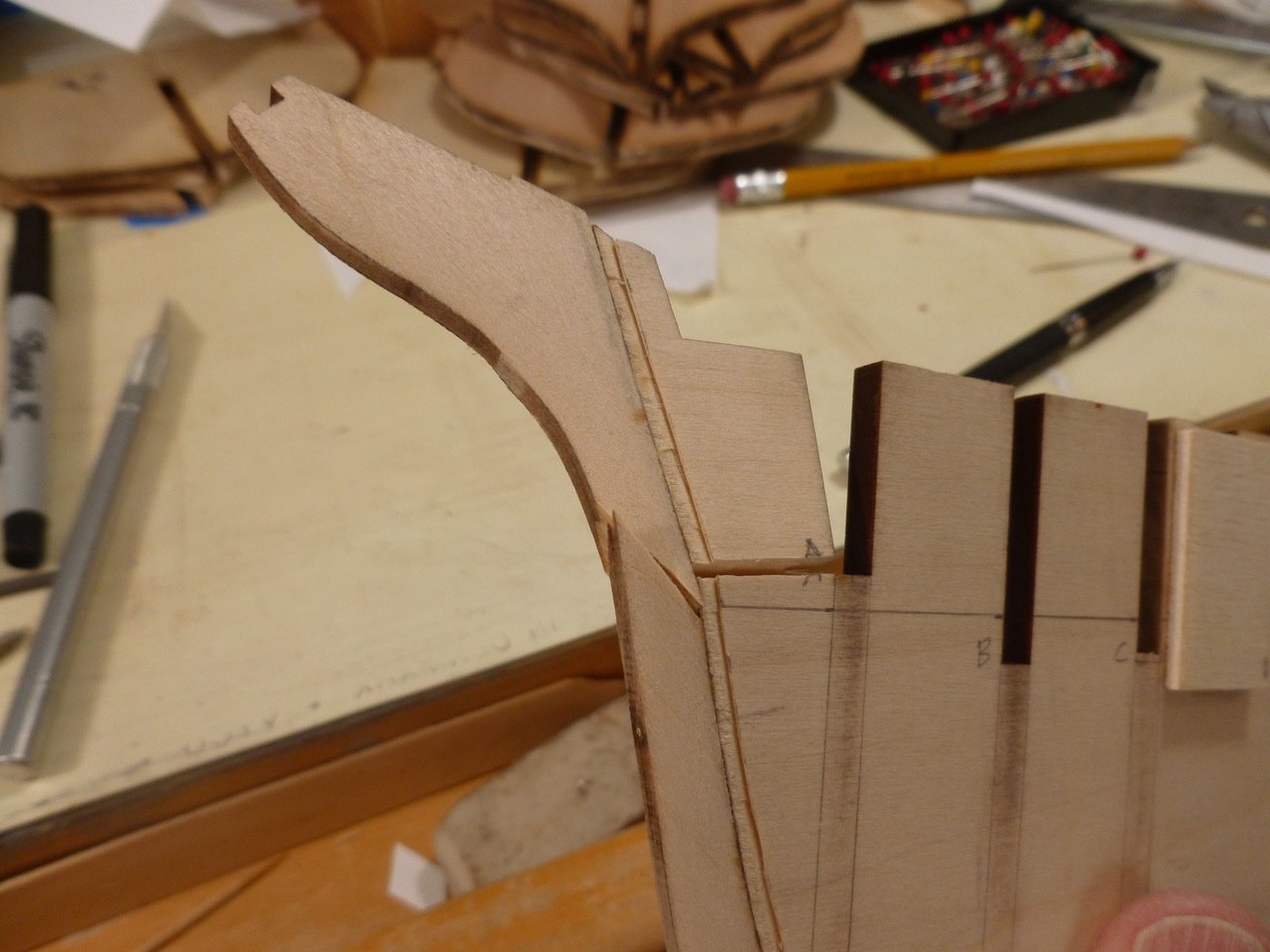
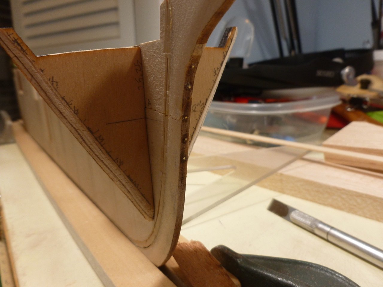
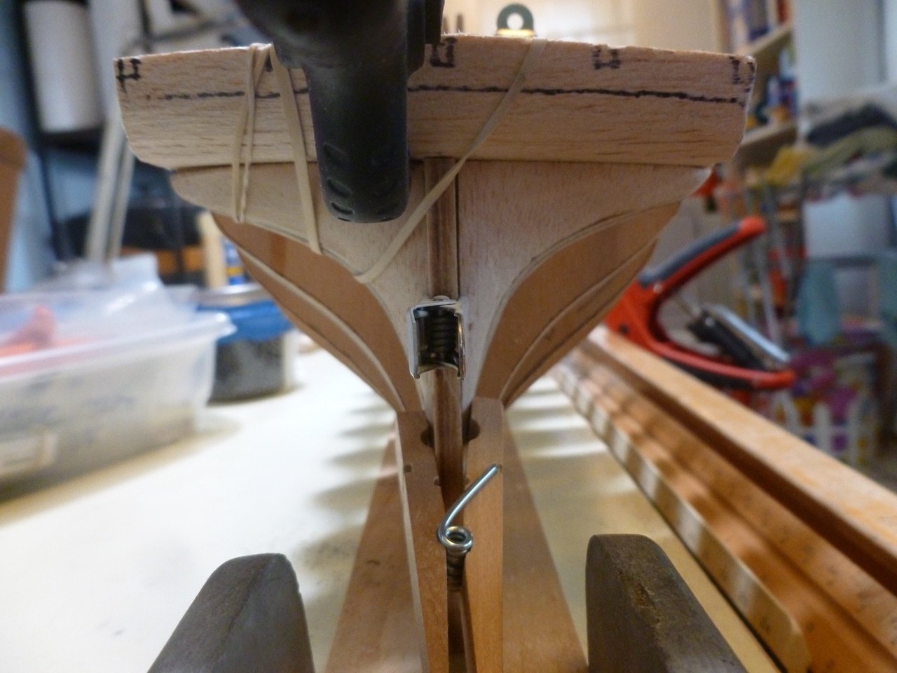
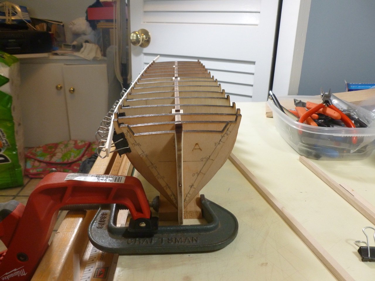
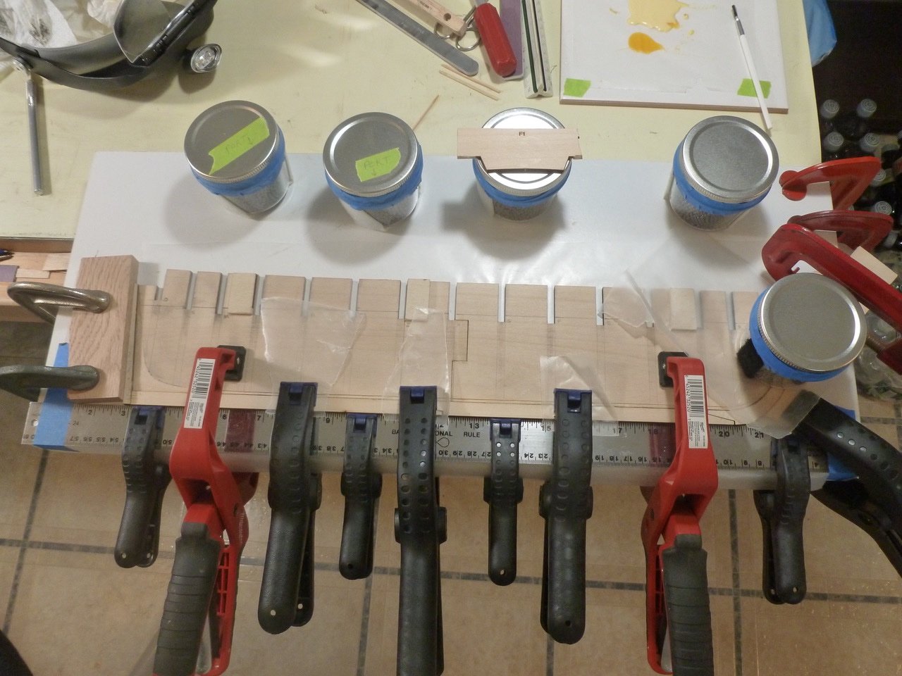
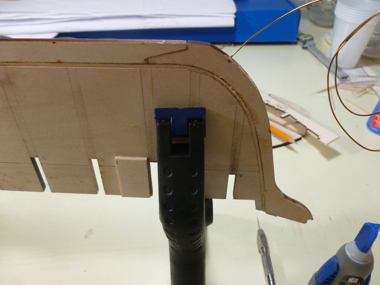
 This is a log of the Charles W. Morgan, chosen as an opportunity to expand my modeling horizons, and for no other reason than the Admiral and I took the kiddies to Mystic Seaport over 30 years ago and spent a cold day traipsing around the ship. First, a thank you to those who have gone before. I have learned a lot, seen build quality I can only dream about, and thoroughly enjoyed the consistent thread that combines abject misery with the sheer joy of each challenge met. My goal is maintaining the discipline to go the full journey, which apparently is by no means assured. I’ll skip the unboxing comments other than to say everything was there except for the ship’s bell, which was forwarded in short order following my request to Model Expo. I chose to cut the rabbet prior to assembling the keel parts. An X-acto no. 17 chisel blade was helpful in tight areas. The jars of shotgun pellets, which served as ballast on a prior RC build, came off the shelf as a counterbalance to allow extending my work board over the edge of the desk. This gave clearance for clamps. The laser cut joint required shims. Brass wire and medium CA pinned the parts together after the glue set. The keel clamp is two wood strips anchored at one end by an old saw vice, and at the other by C-clamps. While massaging the bulkhead slots I discovered that all the keel slots were cut with what appeared to be an out of alignment laser (?) which prevented the bulkheads from fully engaging the keel slots and which twisted the alignment. If left un-filed this could have resulted in bulkheads out of square with the keel. To help maintain alignment I filled the outboard bulkhead spaces with 1/4 inch square strips of lengths to match the bulkhead spacing along the keel centerline. Bulkhead setting was assisted by a small framing square, age unknown. A test fit showed a reasonably straight start. Reading ahead the instructions indicated that the bulwark stanchions should be installed with a slight tilt per a detail drawing. This looked to be a roadblock so I cut a bunch of stanchions and punched out a piece of the plank sheer to review options. The first issue was that the 3/32 inch stanchions didn’t fit the 3/32 inch holes in the plank sheer. Each stanchion needed a slight trim (28 passes) on two sides at the sanding block. Now, how to set a tiny stanchion vertical in one dimension and angled in the other. My first thought was to push a scrap of wood up against the bulkhead, and align the stanchion with that. But that only works at a bulkhead and is awkward at best. The current thinking is an alignment jig (the stanchion is not yet glued in the photo). It fits over the plank sheer, has one surface for vertical alignment, and an edge set at the stanchion angle. Once the stanchion bottom end is trimmed and the stanchion hole is filed at one side, the stanchion is placed in the hole. After setting the jig the stanchion is secured with CA. Using this method it appears that the large majority of stanchions could be pre-set before the plank sheer is installed. Exceptions would be at the bow and stern where the plank sheer rises. Seems like a plan but we’ll see how reality and the CWM rabbit hole impact it. If you see any deal killers please chime in. Then the stem broke. Actually it wasn’t the first break, which occurred when I breathed on one of the mast slots in the keel. That was fixed with cover plates on both sides of the mast slot, along with plates on the other mast locations. While mucking about with the stanchions an errant elbow trashed the stem. Part one of the fix, after gluing the parts, involved more pins drilled as deep as the little bit could reach. Part two will be the supplemental support provided by the bow filler blocks which are being fabricated. I’m hoping there will not be too much tension on the stem during rigging, but I have no experience with long bowsprits so we’ll see how it goes. The counter and stern support blocks are installed. Reminds me of my first day in high school. After we were dismissed one of the school’s finest demanded that four of us climb into his convertible and squeeze down on the floor. He passed over one newbie who had a head full of shaving cream (“I ain’t gettin’ no lanolin on my tuck and roll!”) He then chauffeured us about 10 miles out of town and onto a deserted road in the woods where he dropped us off. When we asked which way was home he said “You’ll figure it out.” Thanks for viewing. Steve
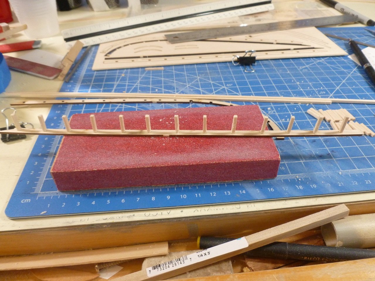
-
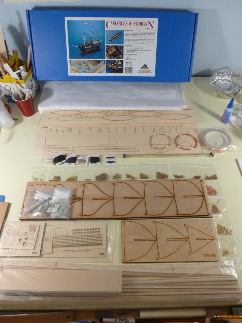
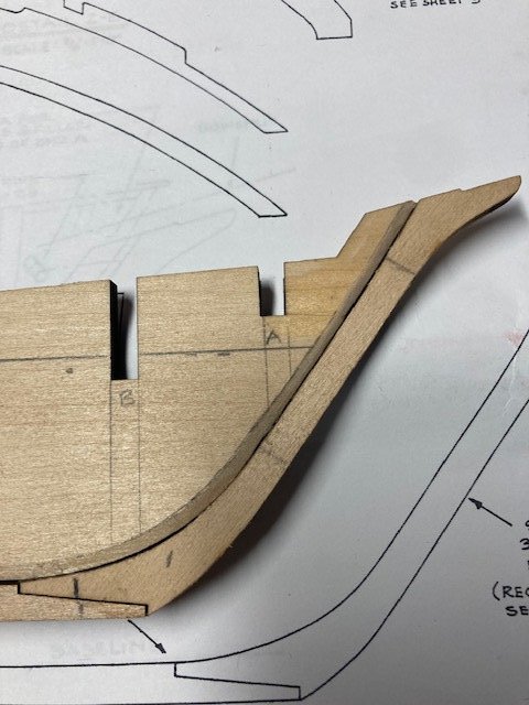
 I recently completed the US Brig Syren. In my last post of the Syren log, I indicated that my next build might be the Constitution. However, after seeing the scale of the Constitution (48") and looking ahead to the size display case that would be required to display her, I decided against it. Instead, I am now embarking on my fourth build, the US Brig Niagara. The Niagara is a little shorter (43"), so I think the display case for it would be more manageable. And, based on some logs I have reviewed, the Niagara build is very similar to the Syren in many aspects. So, here I go. I ordered the kit from Model Shipways (see photo). As is typical, I checked the parts list against the contents and found that the ships bell was not included and I was short some blocks and nails. Everything else was in order. I labeled the size of the various bundled wood strips for quick reference. The kit comes with 6 detailed plan sheets and an instruction manual which I gave a precursory review before getting started on the build. I also jotted down a few notes that I thought would be helpful from my review of a few Niagara build logs. I decided to deviate from the instructions and start with the quarter boats and stern boat. I glued the various laser-cut lifts together and secured them. While waiting for them to dry, I turned my attention to the one-piece keel. Right out of the box Murphy’s Law crept up. The center keel fell off the work bench and the bow at bulkhead A and stern at bulkhead Q broke off – clumsy me. I glued the pieces and allowed the keel to dry overnight. To mix things up, switching to the center keel, I decided to make the rabbet before attaching the keel, stem, and sternpost. I marked the bearding line on the center keel with a pencil. For the stern bearding line, I made a copy of the plan, cut it along the bearding line, placed it on the keel and traced the bearding line. For the rabbet depth, I laid a strip of 1/16” thick plank flush against the bottom of the center keel and traced a line along the keel. I flipped the keel over and repeated the process. This gave me a good line to follow when bearding the keel. I used an x-acto knife to carefully cut the rabbet. The rabbet was then evened out with a sanding block and flat file. I checked the depth of the rabbet repeatedly by placing a piece of planking against the keel stem. Next, I glued the keel and stem together and allowed it to dry overnight. Continuing, I marked the location of dowels to secure the keel and pre-drilled holes in keel and stem. Also, I pre-drilled pilot holes for the pedestal mounting screws. The pedestal location is a matter of preference, but I typically locate them 1/3 of the way from the stern and the bow stem. I applied carpenters glue to the keel and secured to the center keel with brass pins inserted into the predrilled holes and applied clamps to hold the keel in-place while drying overnight. Before adding the stern post, I deepened the rabbet. The stern post was then glued and pinned. I cleaned out the rabbet of some glue with a flat file. I’m glad that I created the rabbet before adding the keel – it was much easier. Sanded the exterior and interior of the quarter boats and the stern boat to a rough finish with sand paper and a Dremel. I will apply some wood filler to even things out. I won’t spend much more time on the interior because once all the thwarts, seats, gratings, etc. are added much of the interior will not be readily visible. Also, I'm afraid to make them too thin. There’s a lot more to be done on these. I plan to jump back in forth between the boats and the ship while glue is drying and to break the monotony. Moving on to the bulkheads. I beveled bulkhead A. I took the advice of some other build logs and assembled bulkhead A and the bow filler pieces, knightsheads, timberheads, and support pieces before permanently installing the bulkhead on center keel. The filler blocks were made from the kit suppled 3/4"x1"x1" basswood blocks - they're a little harder to shape than balsa wood. It took quite a lot of sanding and filing to get the right shape. Once that was done, I made a copy of the filler block top from plan sheet 2 and used it to mark the cut outs for the knightsheads and timberheads. The cut outs were notched with x-acto knife and evened out with a flat file. Next, I cut (from 1/8" x1/8" basswood), test fit, assembled, and glued the knightheads, timberheads, and laser cut top stiffeners. A added a little CA at the joints to further secure the pieces. I did some final filing to further shape the assembly. Next up, bulkhead Q and the stern blocks. Stay tuned.
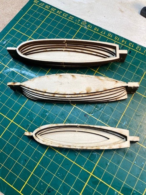
.jpg.01106b7d1bbbcbebe22e25f802c31a94.jpg)
.jpg.9f6eafbbc0c8b29bde6952ce8a169e29.jpg)
-
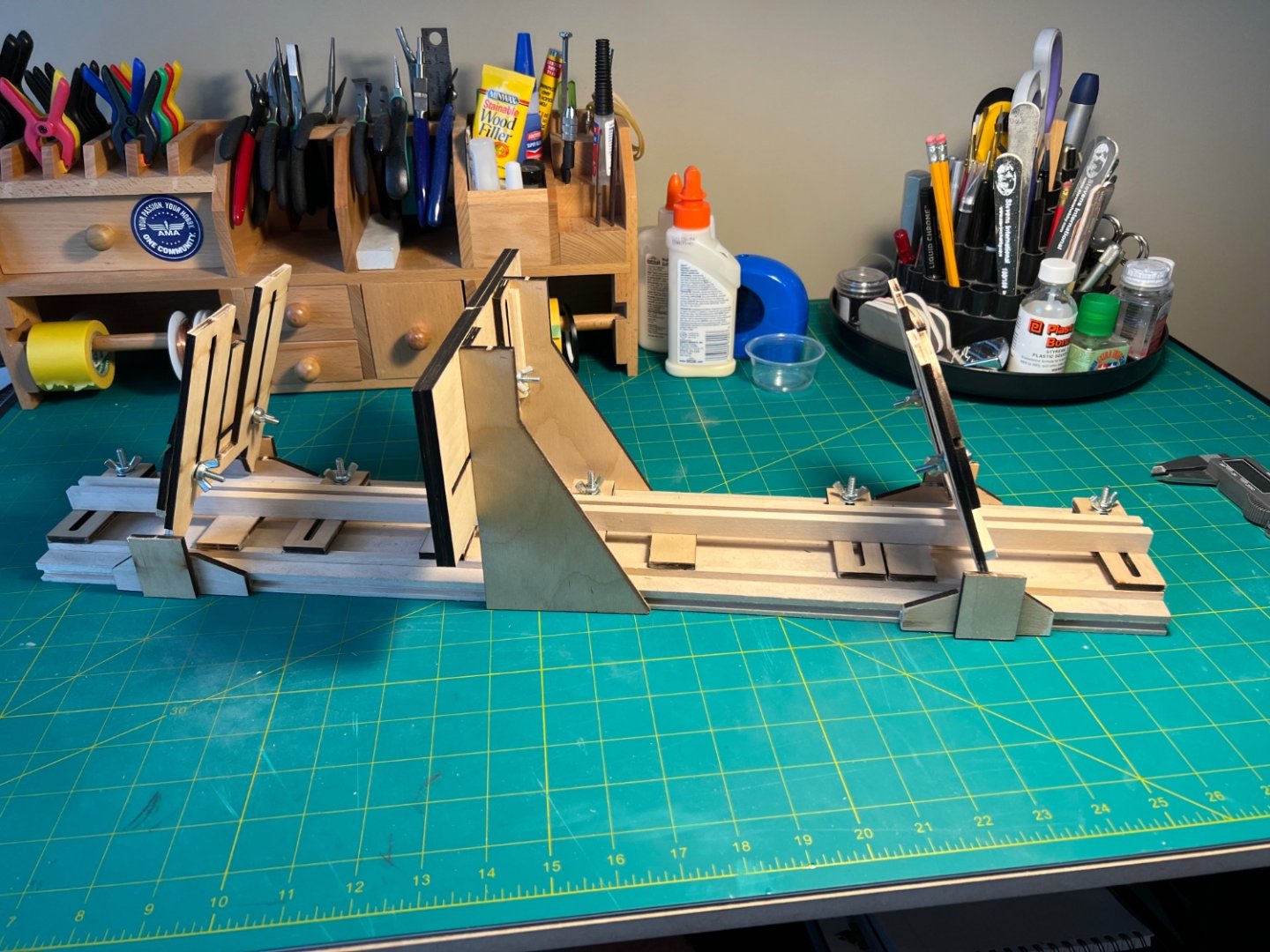
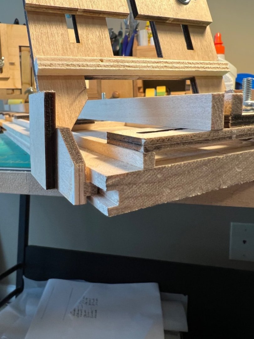
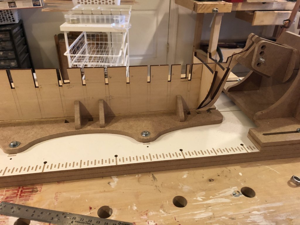
 This will be my first attempt at a full wooden ship build. I have built several plastic model ships (Constitution, Cutty Sark and Charles Morgan, all by Revell) and R/C model airplanes but, this will definitely be a test of skill and patience. I started by building the NRG half hull to get some experience with planking. That went pretty well and I learned a lot! I have always wanted to build a model of the Bluenose, as I am from Canada and have been fascinated by this ship for as long as I can remember. I took the opportunity to dig in deeper to its history by reading Bluenose by Brian and Phil Blackman and A Race For Sailors by Keith McLaren. This ship has a fascinating story and, unfortunately, a sad ending for such an icon of maritime history. I purchased the Fair-A-Frame from Model Shipways, as it looked to be the best way to hold the keel while I worked on bulkheads and everything on the deck (and I was able to get it on sale!). I modified it based on the changes that @Retired guy made prior to his Bluenose build. This is definitely an improvement to the unit and really locks in the jigs that slide along the base. I have been procrastinating since finishing the Half Hull, mostly because I am a bit intimidated with this build. Reading through the forums, there are so many talented folks and high quality builds of this model. Time to get under way and I hope that I can do it justice.
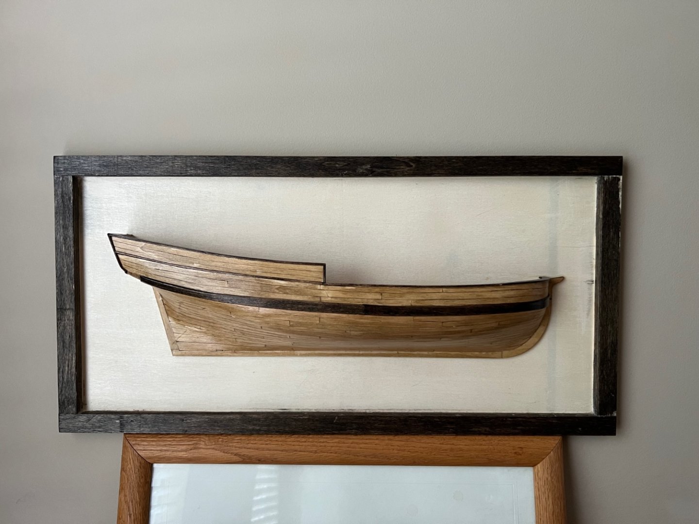
-
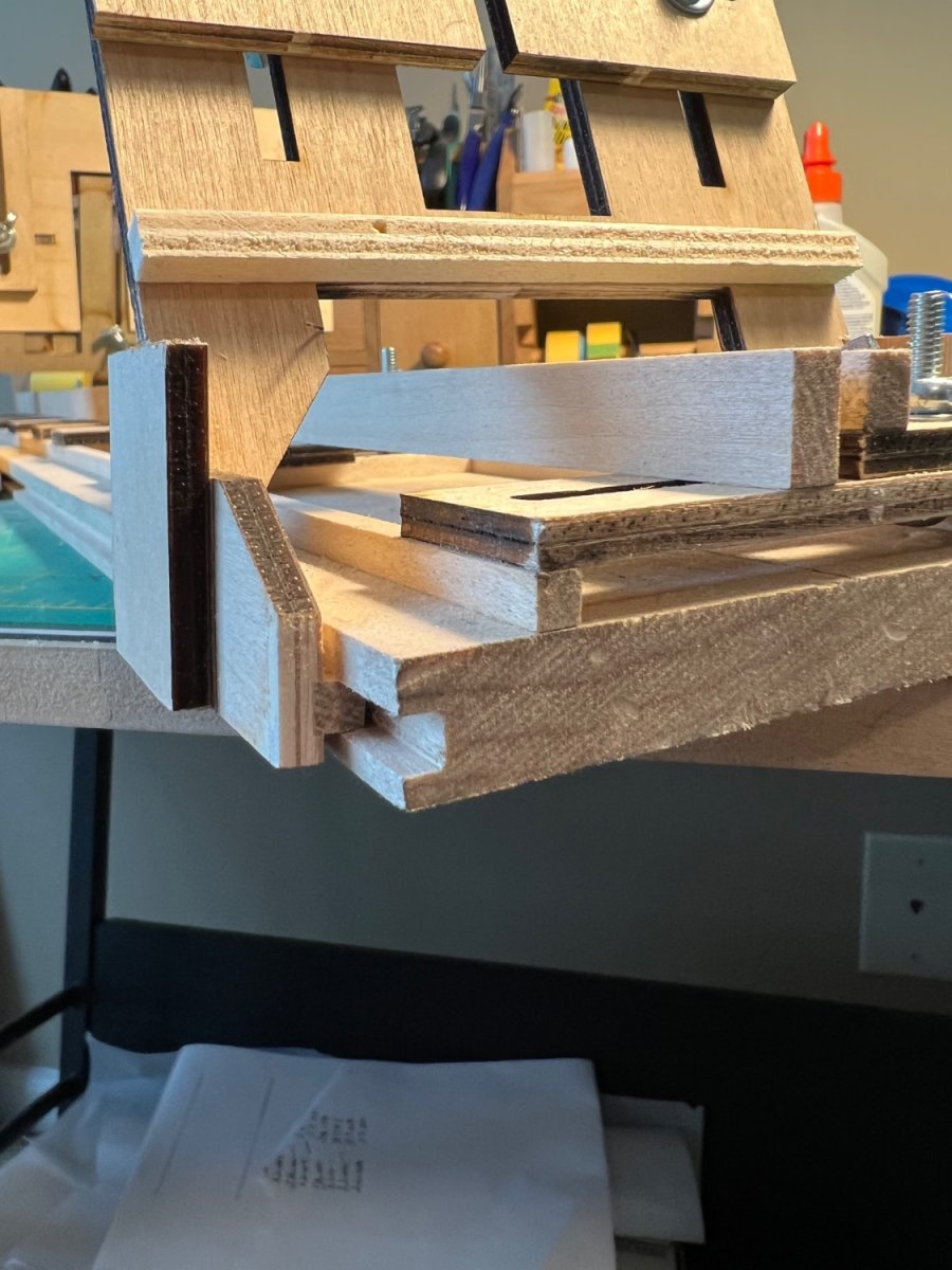
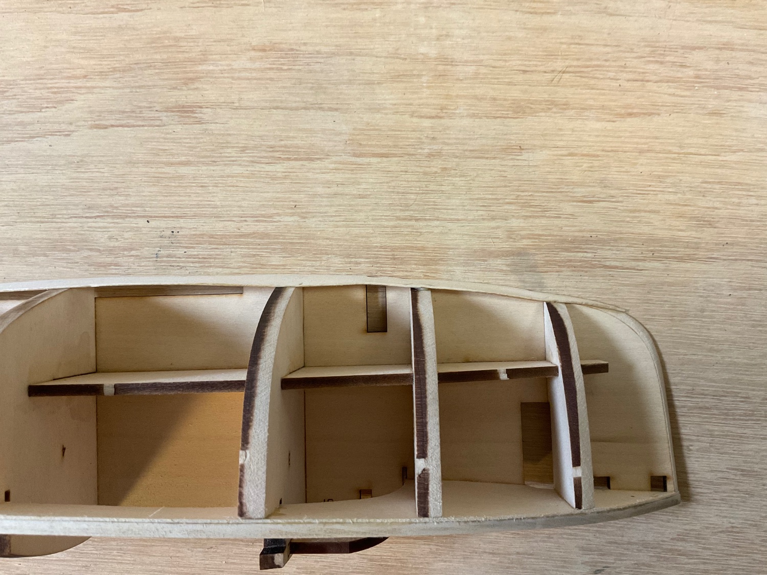
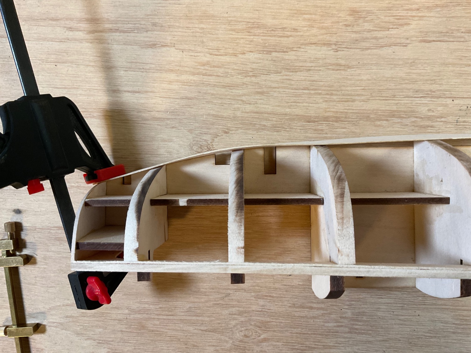
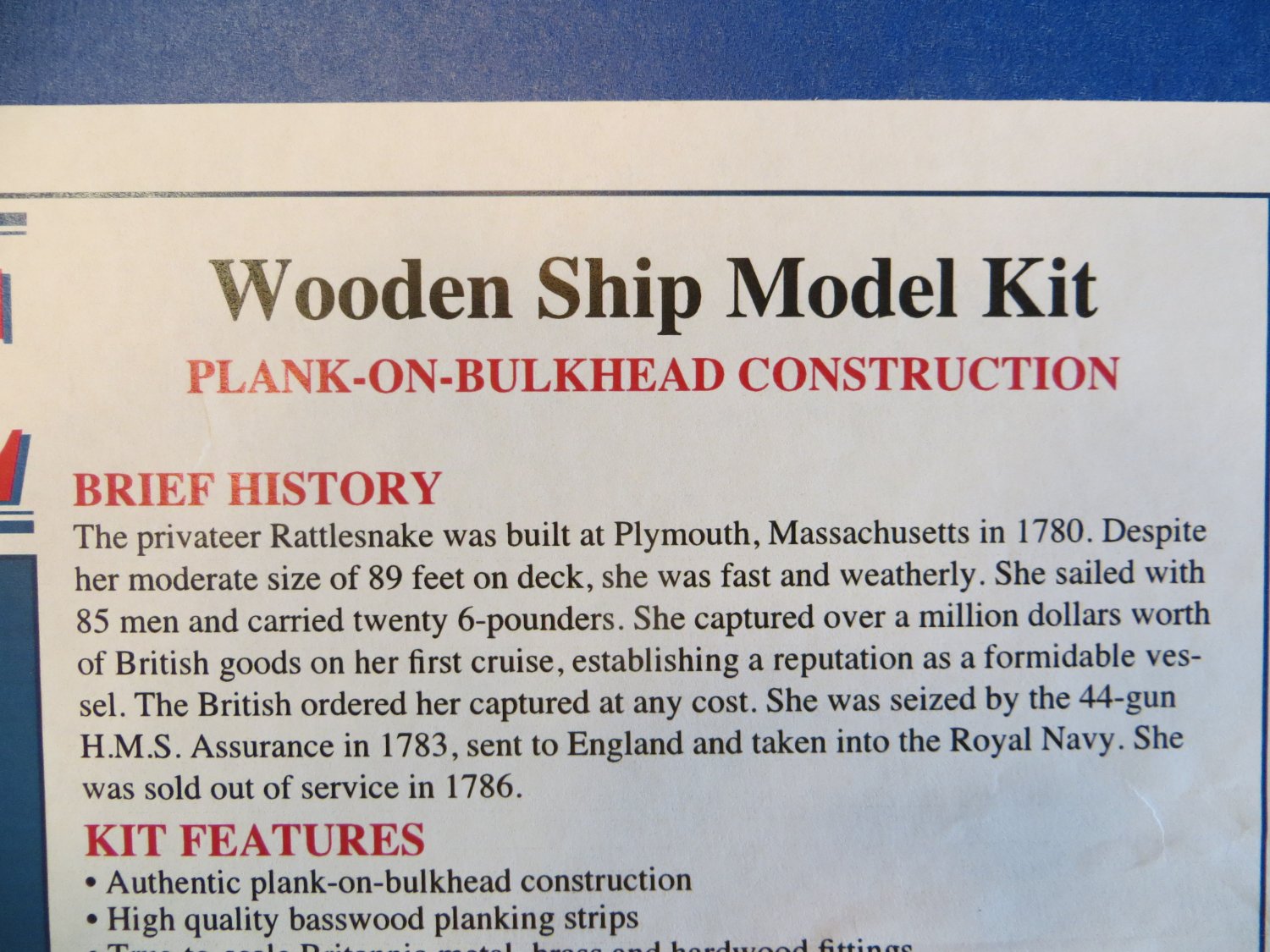
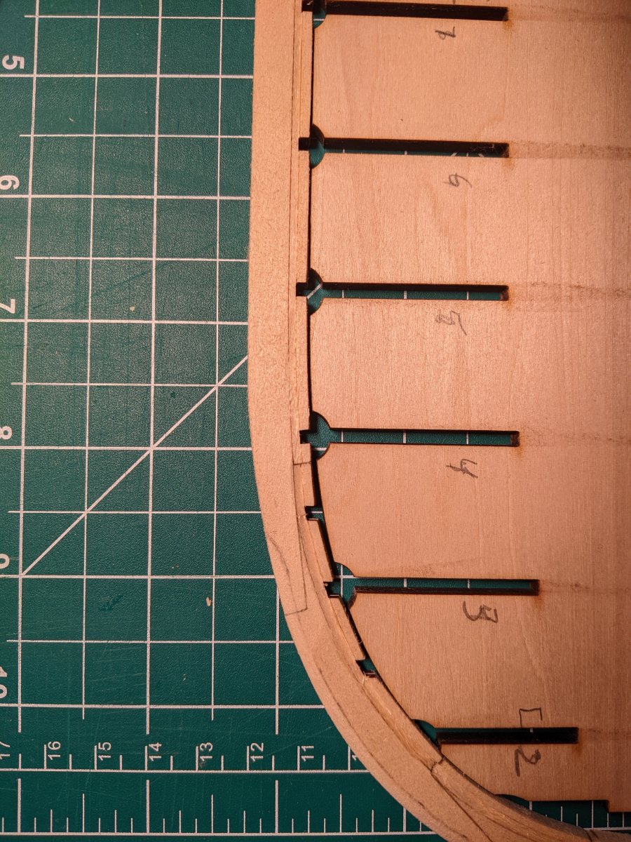
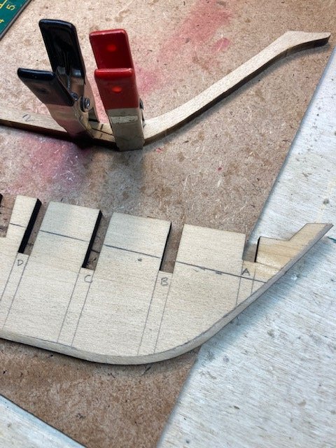
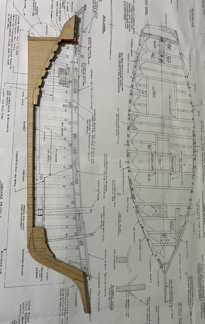
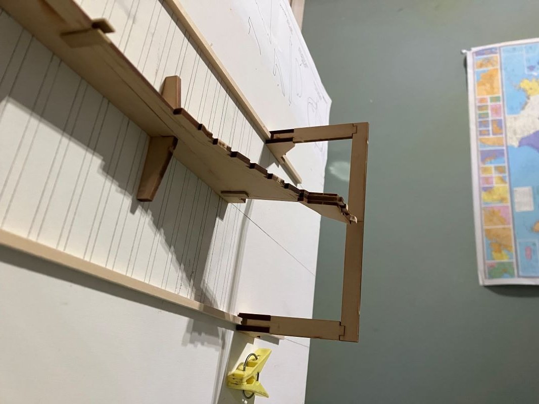
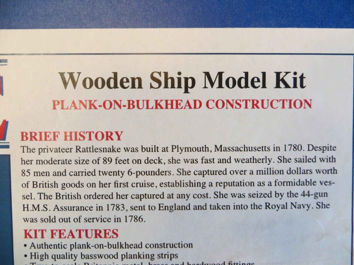
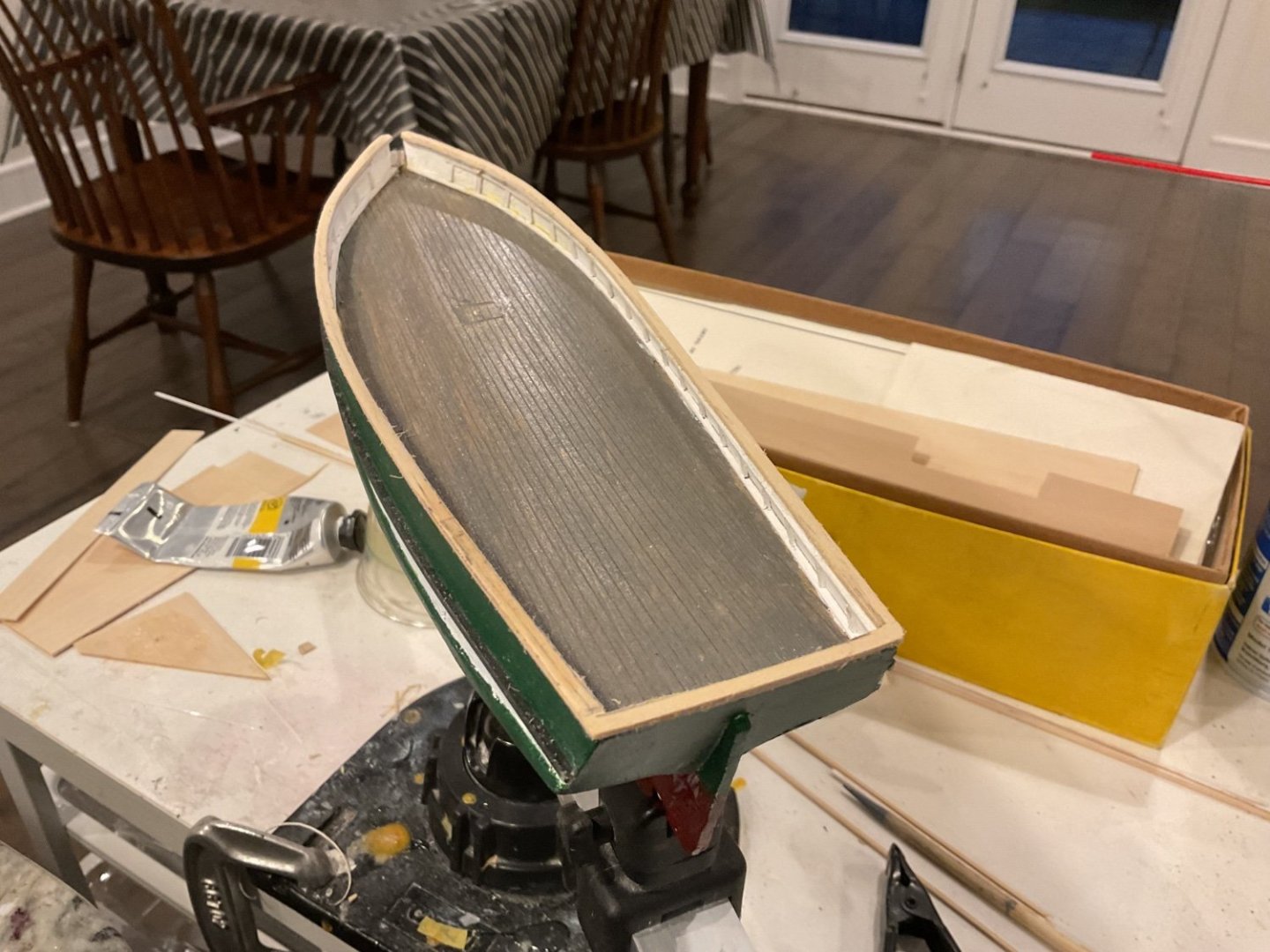
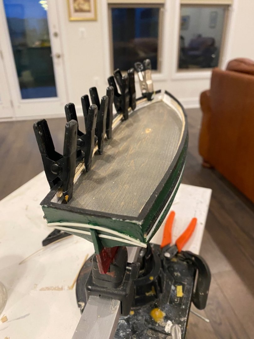
 I received this kit as a Christmas gift from my brother in 2007. That is not a typo; 2007. I wanted to finish the Rattlesnake, then I started my Coastal Pirate and all kinds of life stuff has gone by. I'm finally to the point where I'm comfortable doing this build. Thank goodness it's been patient. The instruction book mentions that a few years of her long life was spent as a yacht - that's what I'm going for. The fish well will be converted to cabin space for this build. This is my first plank-on-frame model and I really like the building jig included in the kit. I built a local skiff years ago with no jig or anything and it's shaped something like a banana. Basic start of the keel assembly: The pencil marks will be erased/sanded. The building jig: As per the instructions, the frame locations were lifted from the plans and transferred through the keel to the jig and board. It took a little while to put everything together, but time well spent up front will result in a more precise build with fewer problems. The board is a piece of straight, square, pre-primed and sealed 1 X 12. I drew the center line and marked the location for the keel support and each frame along the line. Before I glued the keel support, I used a T square and marked each frame. I built the frame clamp bar fixture and marked the lines for the strip runners on the board. I made sure it moved smoothly but stayed firm along the whole route, then nailed it down. All of this is outlined in the instruction manual - which has to be read and reread over and over. Now that everything is set in place, it all lines up just right; it's level, plumb and square. Next, I will cut the bevels in the frames. Comments Welcome, especially from other Berrys - Kenneth
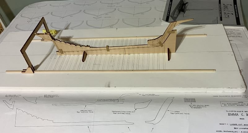
-
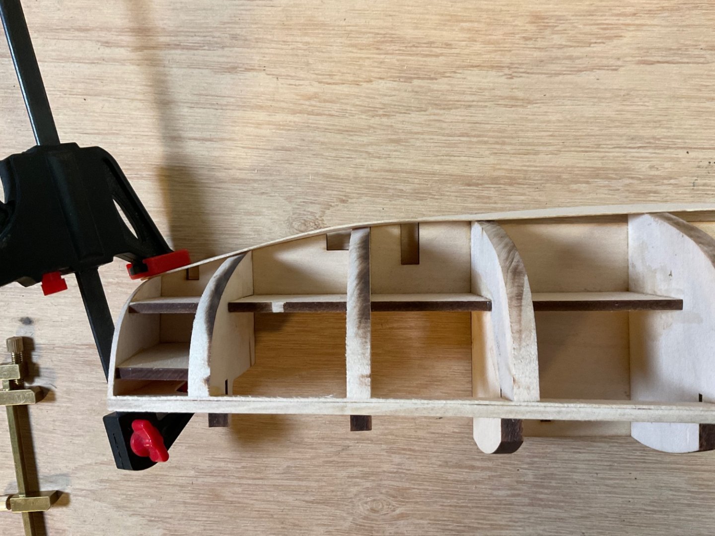
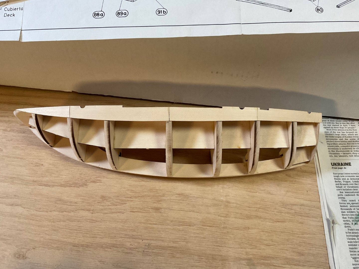
 Having built the Model Shipways shipwright beginner kits by David Antscherl, I thought I’d try out the latest kit by Antscherl being offered by Model shipways, the Nonsuch 30 catboat in 1:24. I just started the hull planking, up to this point the build process has been rather straightforward for a plank on bulkhead kit. However, the start of the planking process has not gone smoothly. The Garboard plank is the first one to be placed on the bulkheads. I could not get the plank to lay smoothly on the bulkheads and keep the precut holes lined up with holes in the spine. The next two pictures show how warped the plank turned out. I will have to remove this plank and reapply it. My solution was to cut the plank into 4 pieces and lay them individually. I just had to sand the edges of the pieces a little to get a good fit. The bulkheads are rather thick, so this worked out ok. We’ll see how the following planks lay down.
- 27 replies
-
- 2
-

-
- Nonsuch
- Model Shipways
- (and 1 more)
-
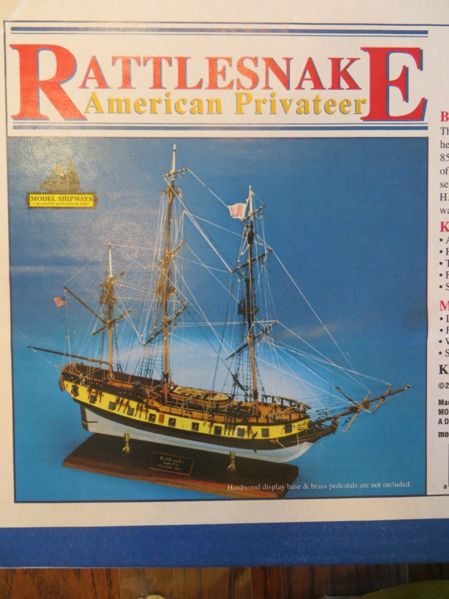
 Introduction Rattlesnake is my second model build. I finished Bluenose 1 back in June. This took me 2 years to finish. I decided to take a little summer break from modeling before starting Rattlesnake. I think that it was a good idea to give modeling a rest because I am now very eager to go. I consider my “official start date” as October 8th. In August I completed inventory of the kit. I also spent a lot of time throughout 2022 studying build logs for Rattlesnake and putting together my own build plan & instructions. I created an Excel spreadsheet to compare the instruction manual from Model Shipways, the plan I used for Bluenose and several build logs from this MSW website. Using all this information, I created my own plan. I thought about purchasing the Bob Hunt Practicum from Lauck Street Shipyard. But after reading JS Gerson’s build log, I decided not to. The Mamoli kit seems to be quite different from Model Shipways and I’m not ready to do a major kit-bash. I do plan on buying the masting & rigging practicum from Lauck Street. But that’s a ways off!! I share this thought process for anyone who is considering how to proceed with their own Rattlesnake build. I look forward to sharing my build log with you and I encourage you to share any comments or words of wisdom that will help me with this project! Thanks! Here are a few pics showing the completed inventory and the kit box cover:
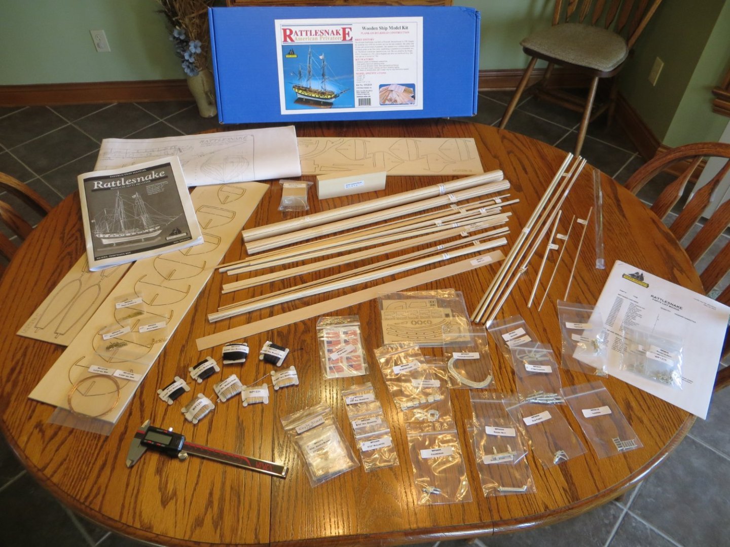

-
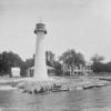
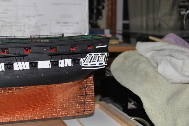
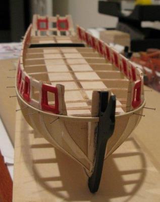
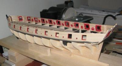
 Gjoa was used by Roald Amundsen to traverse the North West Passage from 1903 to 1906. She was built in 1872 and used as a herring fisher until Amundsen purchased her in 1901. This kit is an old Model Shipways “yellow box” kit that I purchased on eBay several years ago. These kits have minimal instructions and just a few parts: a machine shaped solid hull, some blocks for deck houses that are never the right size, dowels for masts and yards, and a bag of metal fittings. I worked on the kit off and on over the last several years but failed to take any photos. Once I finished the paper model of the liner United States I decided to attack the Gjoa seriously. Attached are a few photos showing the construction of the cap rails and the pin rails. For the cap rails I traced the out line of the bulwarks onto a piece of sheet wood, widened the line to the cap rail width, leaving plenty of extra wood. The rough rails were then glued in place and shaped to fit. The pin rails were done similarly with lots of test fitting with final shaping after they were glued in place. In the photo the port side pin rail has just been glued .
- 27 replies
-
- 6
-
-
- Gjoa
- Model Shipways
- (and 1 more)
-
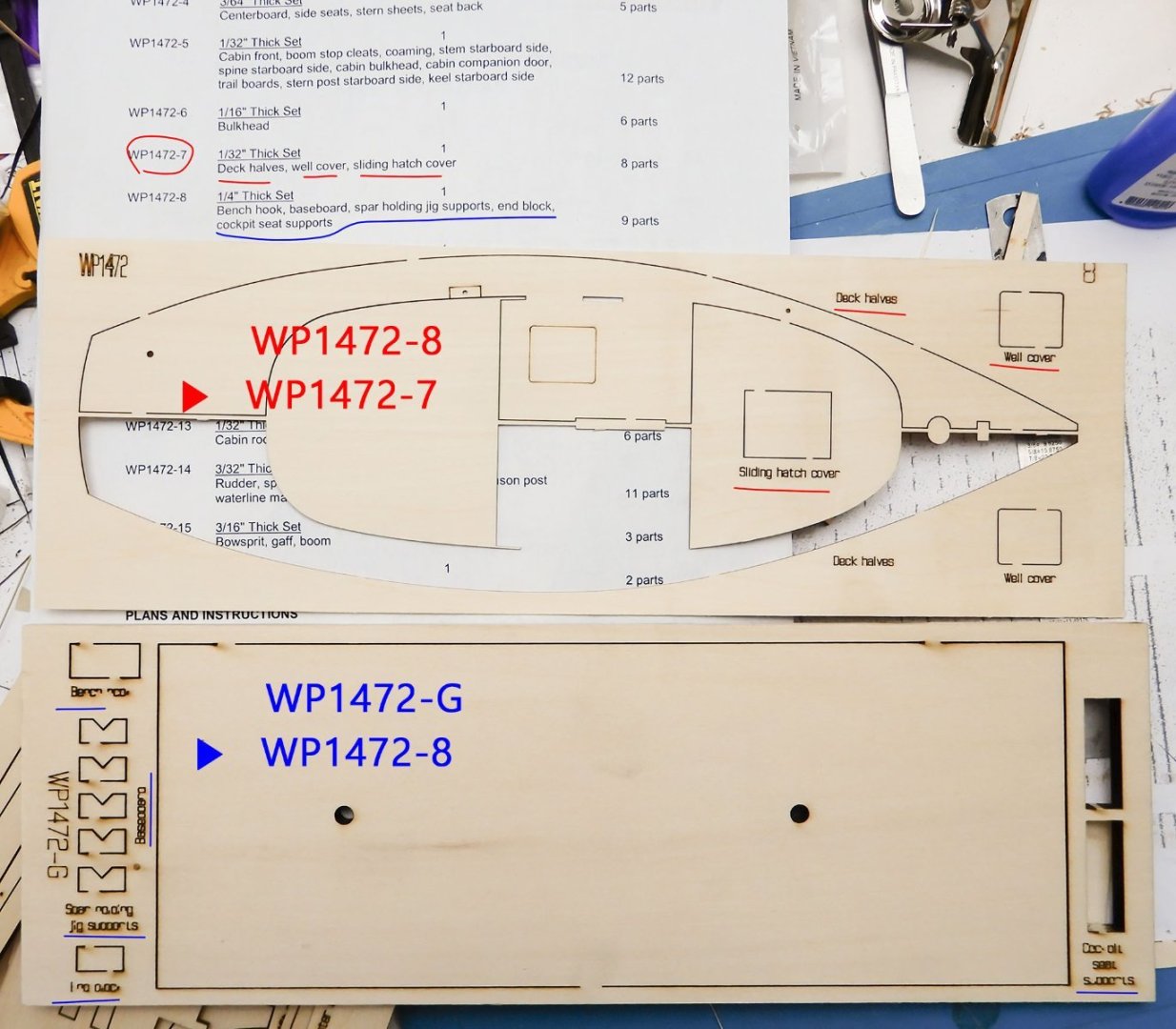
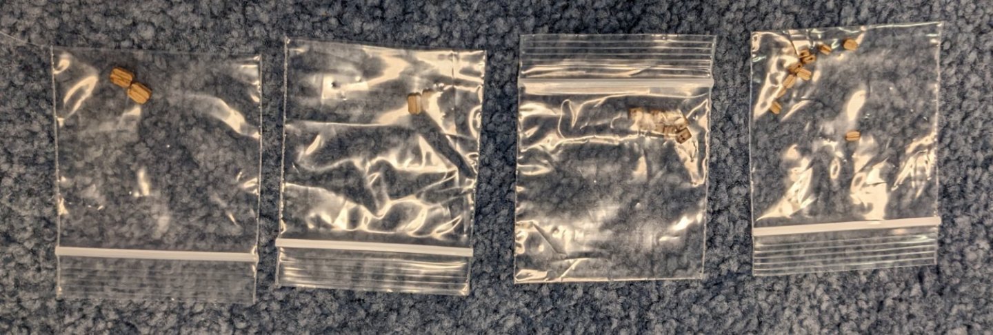
 It may be too late, but thanks to Bryan Woods for watching my build log. It is good to check every part in a new kit, but this case is a bit embarrassing. When I checked the part list paper of the Smack kit, I found that part 7 (WP1472-7) was missing. I stopped to build it and requested a replacement part from Model Expo. Two days later, I was building the kit. I decided to build until I needed the missing part. I suddenly found that the part list was misprinted. (Check the above picture) All the parts were in my kit, and there was no more obstacle to finish my project! I request an order cancellation to Model Expo... 🤣 It is time for another sprint. 😎
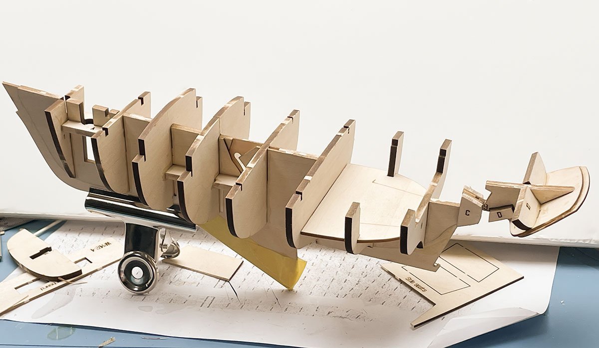
- 1 reply
-
- 8
-
-
- Model Shipways
- Muscongus Bay Lobster Smack
- (and 1 more)
-
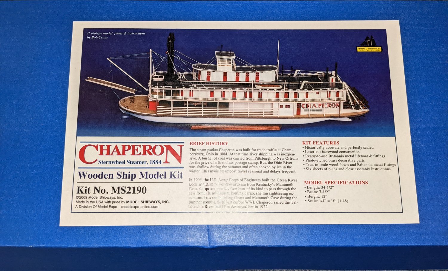
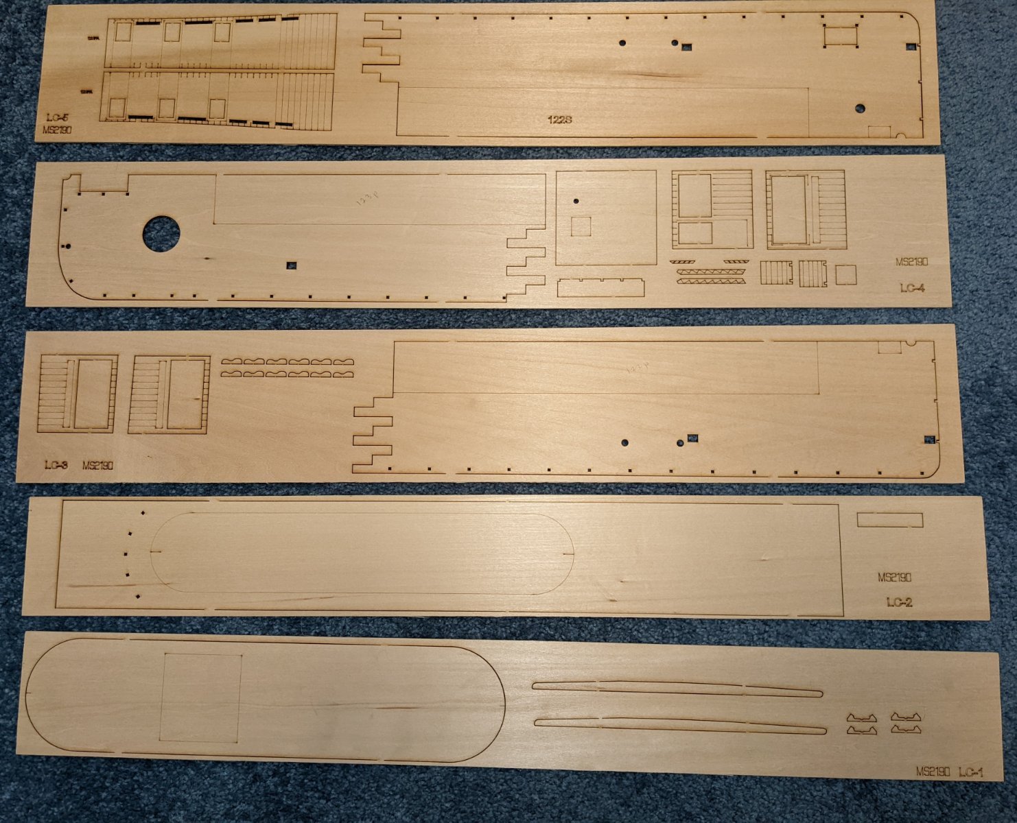
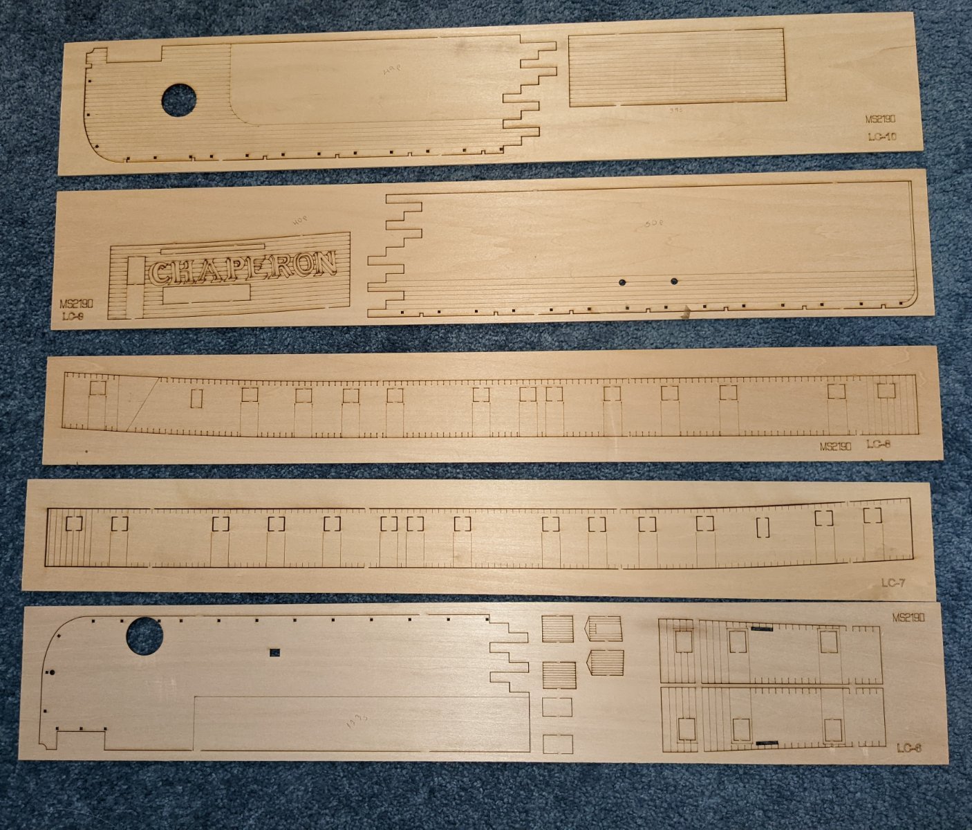
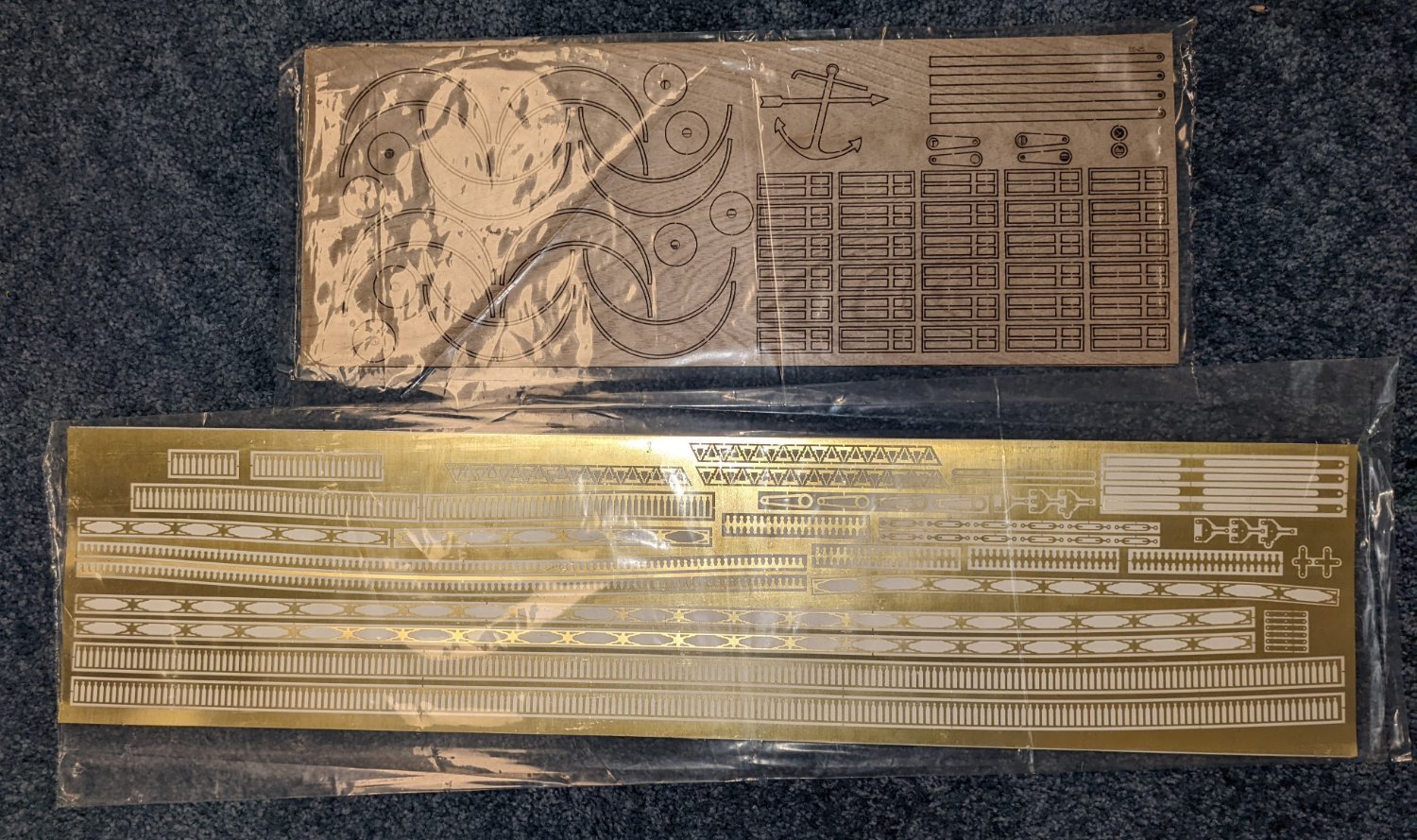
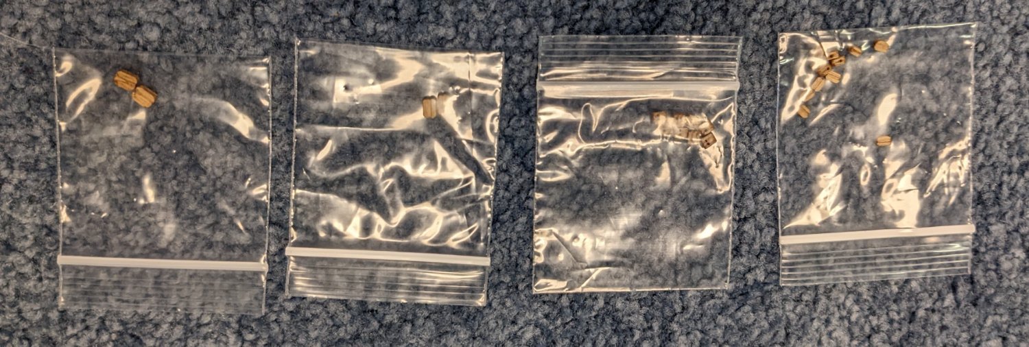
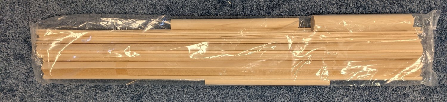
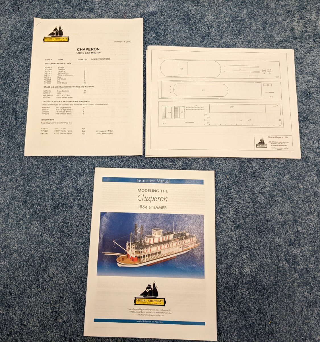
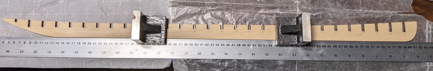
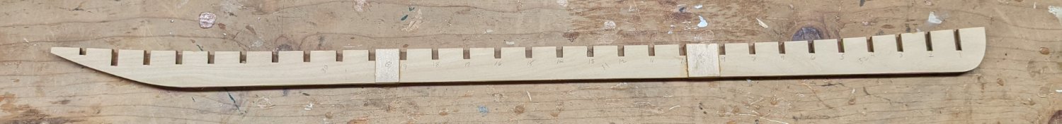
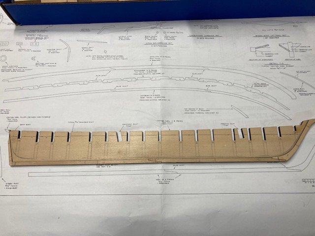
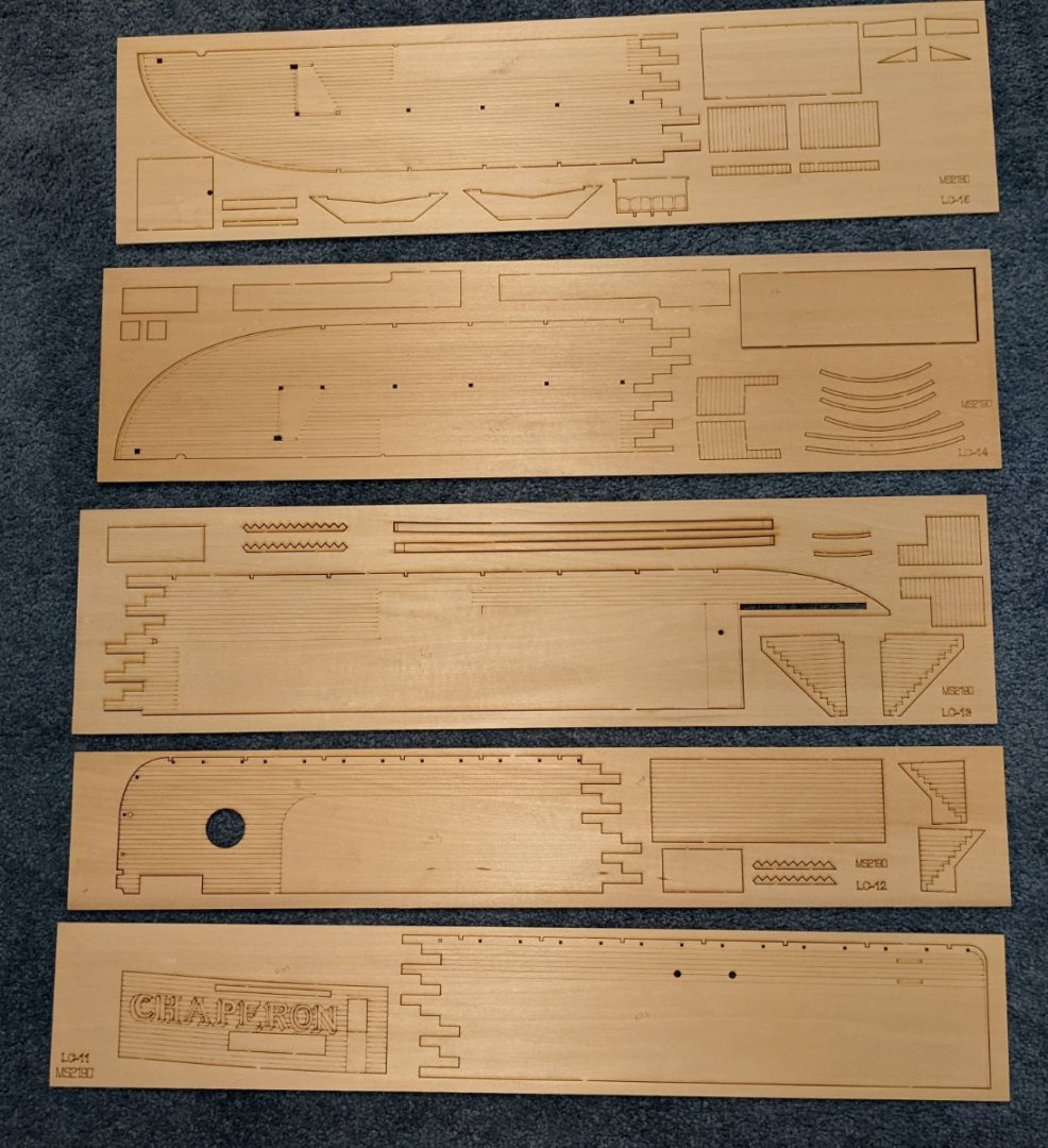
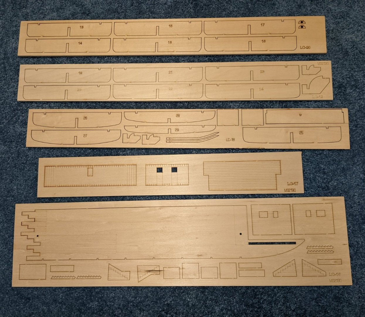
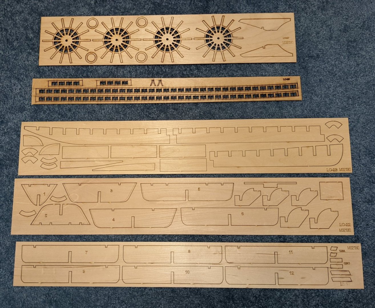
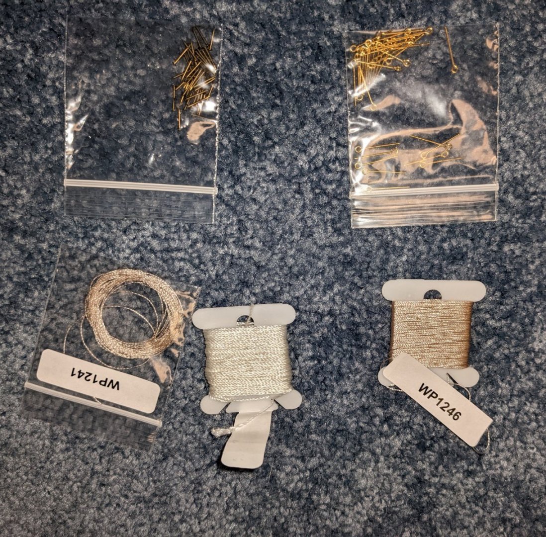
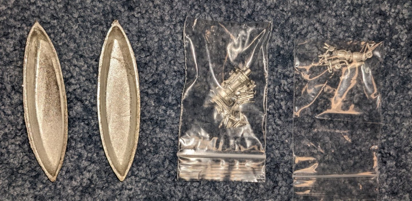
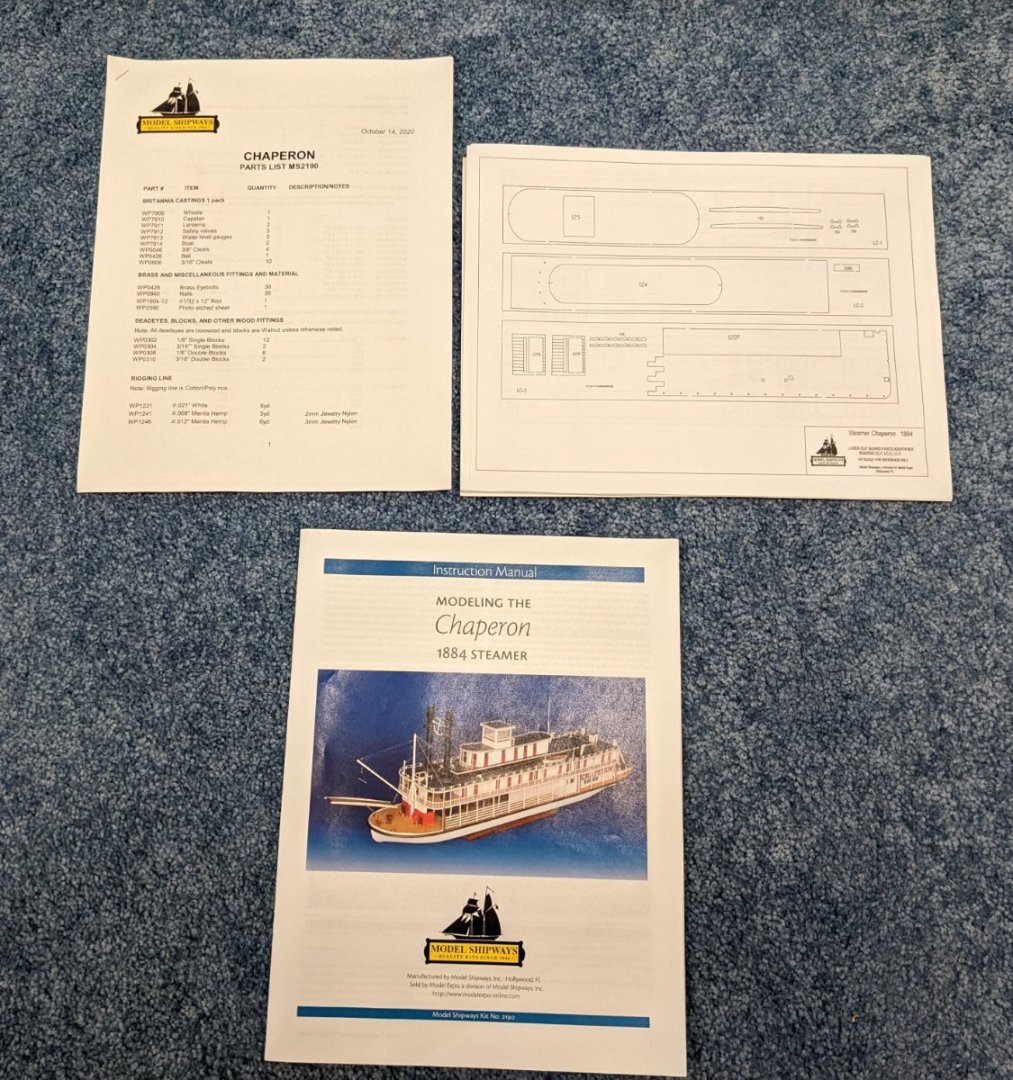
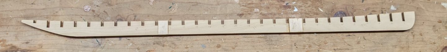
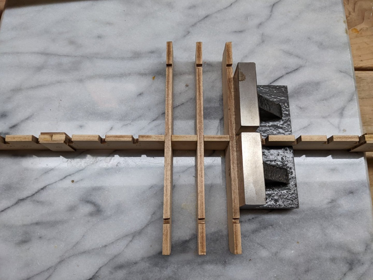
 Just completed the Secret Vessel "Morel". What I call a "quick win" as it only took a couple months to complete. For those of you who have not seen the Morel model, I recommend you check it out. It is a quirky little model that is easy to build but looks really neat. And a definite break from the usual year long builds of most models. Anyway, Now it is time to put my "big boy pants on" and take on the Chaperon. I am by no means an expert builder - average at best, but as they say - the journey is the destination. And I do enjoy the journey ..... or the build in this case. I would like to say thanks to all who have built, and supplied excellent build logs, that have gone before me with the Chaperon model. There have been some excellent Chaperon builds - I would say museum quality. I will be shamelessly borrowing (stealing) some of the best ideas from those logs as I build my model. I am still too new at building models to have many original ideas of my own. My build will by no means compare to those who have gone before me, but I will have fun. With that in mind I will start right in with the unboxing.... Most people can just skip over this section unless you really are interested in the box contents. There are 27 sheets of laser cut basswood. Note on this sheet and others some of the boards have lines etched in them... With this model they are to simulate planking. Not sure if my model is odd or not, but to me those lines seem very thin (faint). They look like after a coat of primer and paint they would be completely filled in. We will see what happens when I get to that stage, but right off the bat this model may get (shall we say) "interesting". Included with the last laser cut sheet is one large photo-etched brass sheet. pins, eyelets, and some nylon line..... Will probably not use this line as it seems to be pretty cheap. A couple of britannia life boats and assortment of other britannia parts. An assortment of single and double wooden blocks An assortment of wood strips and dowel rods for the build Inventory list of all included parts A 12 page manual with a brief history of the Chaperon and the build instructions. 12 sheets identifying each item on the laser cut wood pieces and photo-etched brass sheet. Not shown, but included are 5 large plan sheets depicting the various stages of the build On to the build.... As with most builds that are larger than the wood sheets, we start by gluing the keel made up of three 3/16 pieces. The joints between the three pieces (under the weights) are reinforced with small reinforcement pieces (B1 & B2). The ruler was used to help keep the keel straight. As you can see, this is going to be a big ship. With the glue dry and the weights removed you can see the reinforcement pieces (B1 & B2). There are a pair of them on each side of the keel. Each of the 29 bulkhead slots have been labeled to help keep track of the bulkheads as they are installed. As so we begin the process of laying the bulkheads. Be sure to remove all the laser charred marks on each bulkhead before installation to insure the glue gets a good grip on the wood. I mention this now and will not mention it again, but that goes for all the laser cut parts. Char marks need to be removed from each piece throughout the entire build. Instructions say to start with the middle bulkheads and work your way out to the bow and stern. This will take awhile as you need to insure each bulkhead is square and need to wait for the glue to dry before moving on to the next bulkhead. It is going to take a few days to get all 29 bulkhead installed.
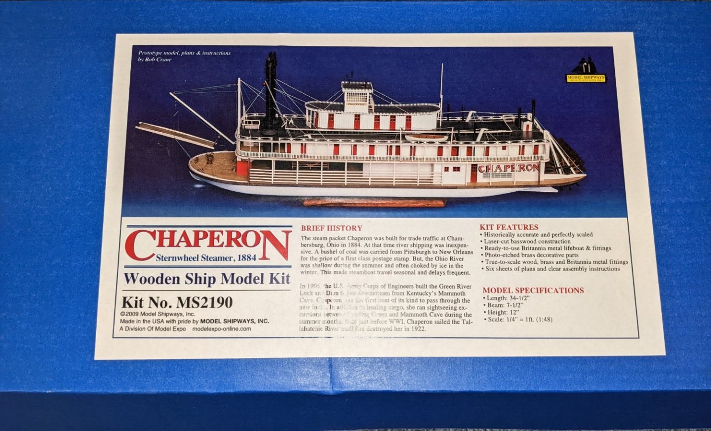


-
 Greetings MSW users. While researching my project I've found MSW to be a wonderful resource. I especially appreciate the friendly and encouraging atmosphere. No build is too small or question too dumb. All are treated respectfully. So unlike much of our world today. I began modeling while in elementary school and continued through secondary school. Mostly cars and airplanes. Simple plastic models and a few wooden airplanes. The hobby taught me about tools, patience and an appreciation for detail. These skills translated well into my later career. I drifted away from the hobby during college and many years of working. After retirement I began to think about building wooden ship models. Something I had always wanted to do. For my first project I bought a solid hull Cutty Sark model by Scientific Models on Ebay. This 1:200 model was about the size of a plastic Cutty Sark I had built during secondary school. While it turned out OK for a first attempt, It was not large enough to do complete rigging. Only the standing rigging and sheets were practical at that scale. At least for my limited skills. Many fittings and details were only approximate representations. The hull had been started and there were a few parts missing when I obtained the kit. Why Bluenose? I was casting about for an interesting but not too complicated POB kit to challenge me and build skills without being overwhelmed to the point of giving up. My wife was pushing for a fairly large sloop rigged boat to become part of our decor. I picked Bluenose for the beautiful and sensuous lines. It also had interesting fittings and rigging, but was not so complicated as a man-of-war or square rigged schooner. The history of the ship was intriguing. Many research materials and build logs are available. Plus my wife found it acceptable. I studied build logs and researched model kits. The three most popular Bluenose kits were Artisana Latina, Billings Boats and Model Shipways. Artisana appears to be the least accurate. Photos and comments in general were not very favorable. The Billings is very popular and it has some construction advantages. However the build logs complain about inaccuracies. Model Shipways kit appeared the most accurate. I was also impressed they allowed for mistakes by including extra wood. I did find at least one inaccuracy in the plans as will be noted later. None had highly rated instructions or plans. At this skill level that shouldn't be a problem though.
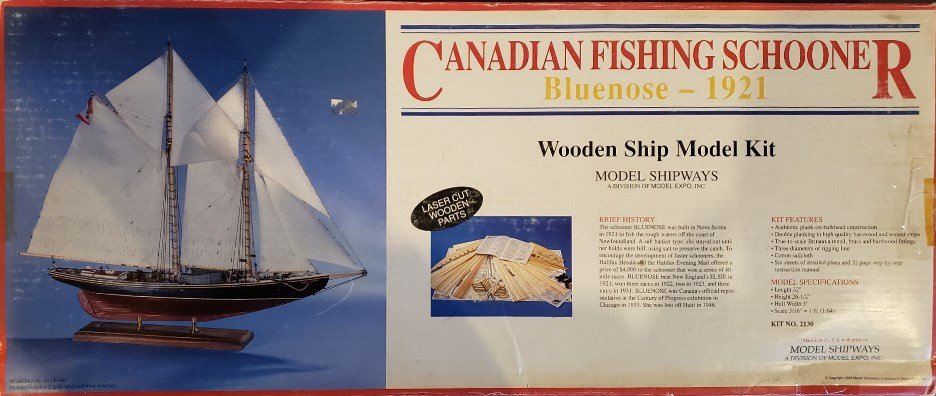
-
 Is it wrong to have three logs at once? Another solid hull to keep me occupied while my other boats are drying, or waiting for something. No rigging and I think this one will be fun. Surprised there are no logs for this boat, perhaps there is a reason? For the low sale price of $39.99 the castings are really nice and the is vastly improved I believe since the cabin is now laser cut and not a solid chunk of wood. I sanded some some of the hull and I’m hoping this will be good practice for the thin bulwarks my phantom requires.
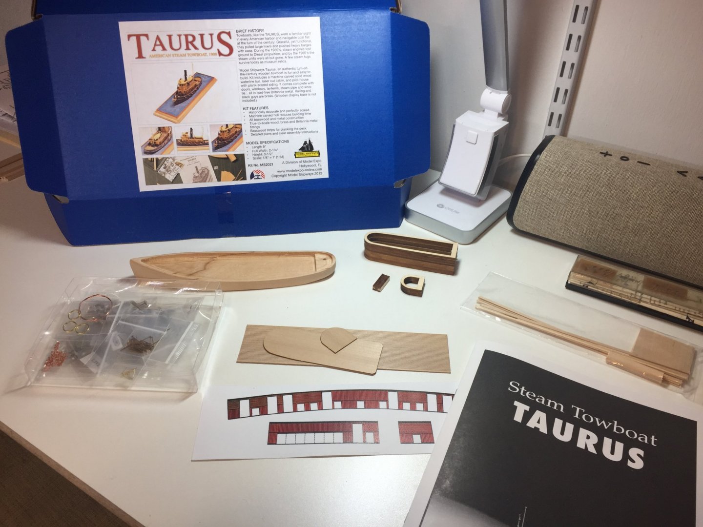
-
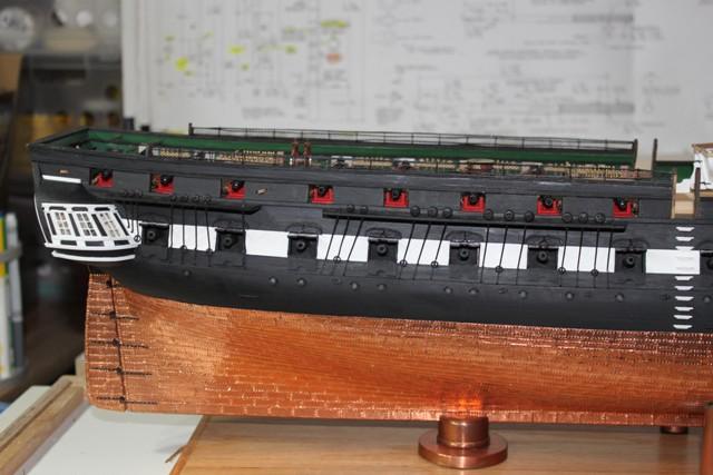
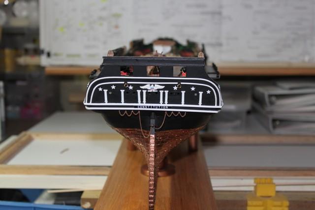
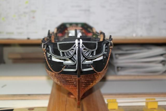
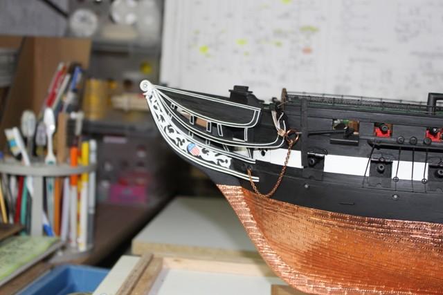
 My name is Geoff and I have been building the MS Constitution. I basically followed Bob Hunts practicum. I am now ready to begin the masting and rigging part. I am very impressed with the other Constitution build logs and look forward to see them all develope Here are a few pictures of my progress so far. Thanks Geoff
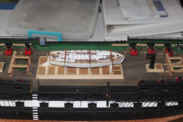

-
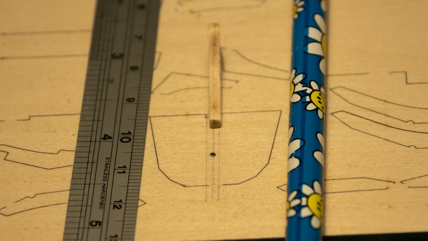
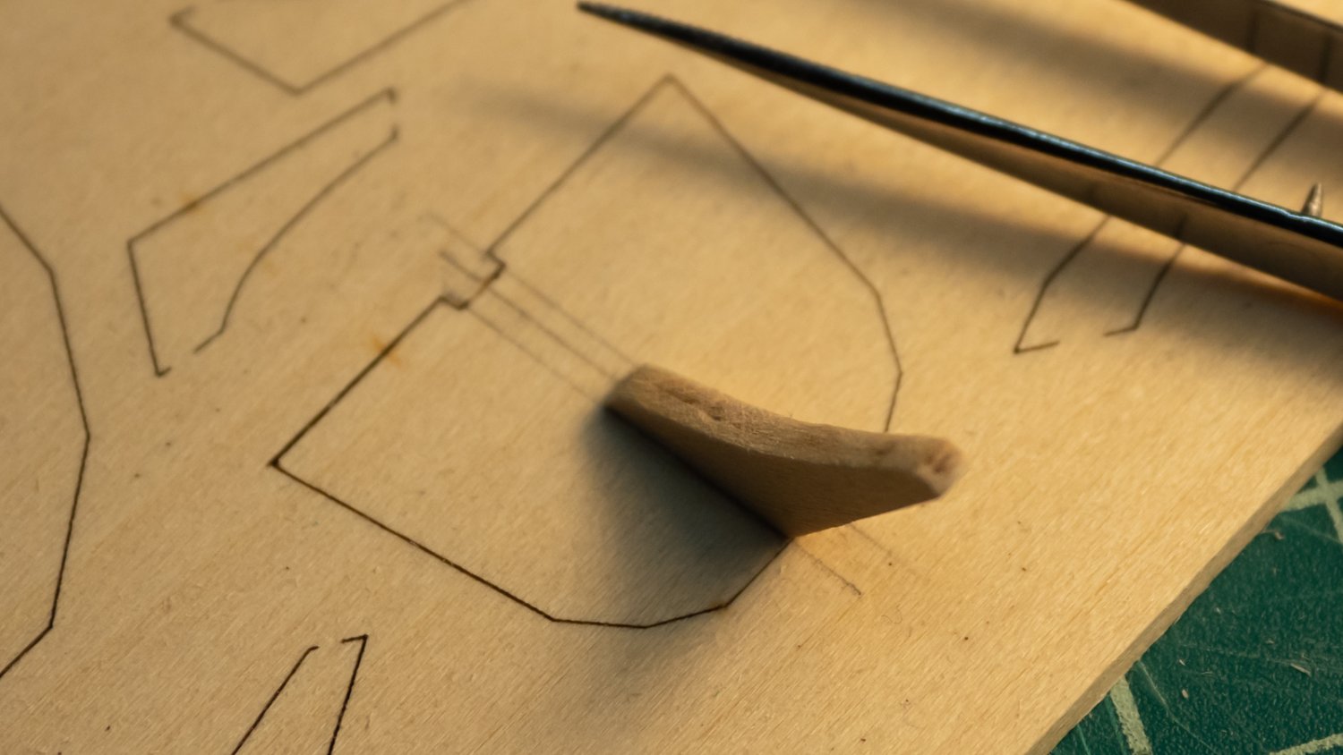
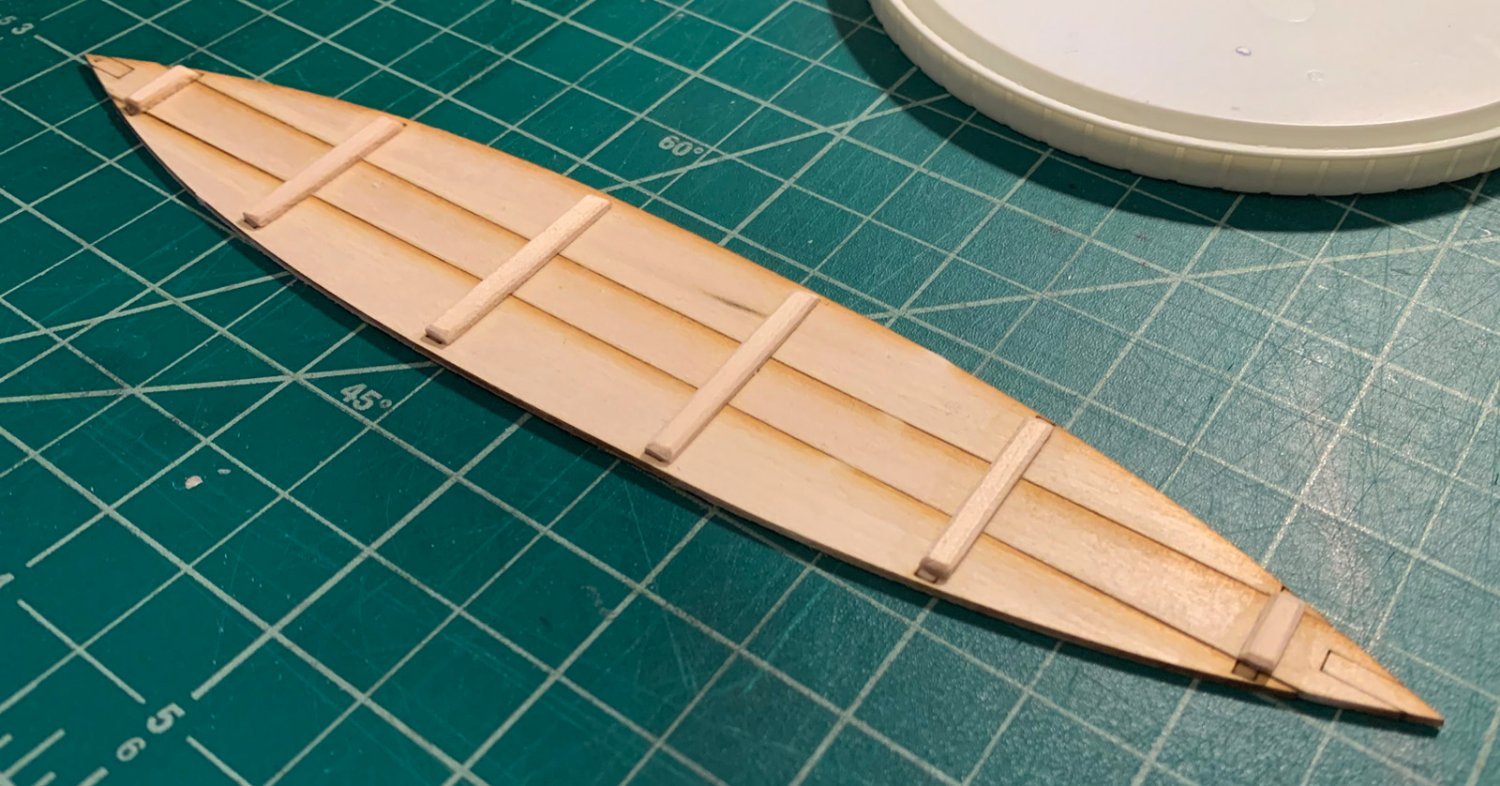
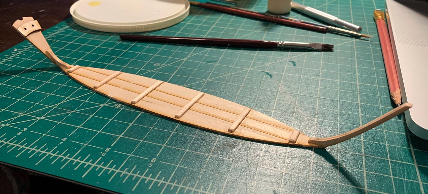
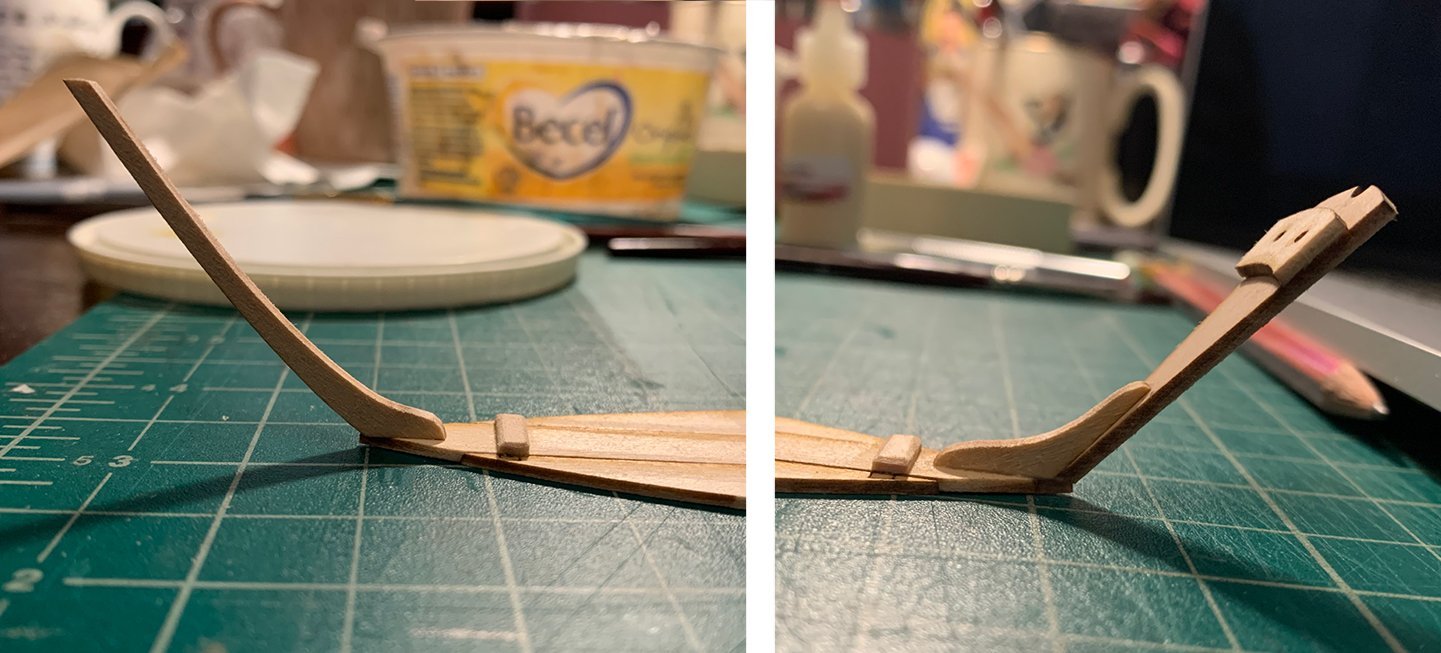
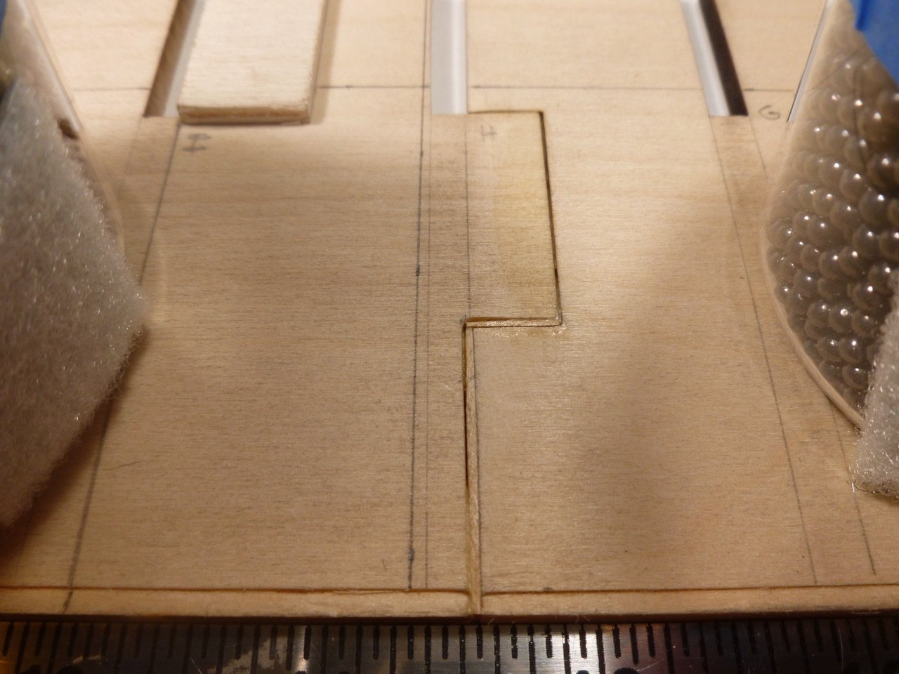
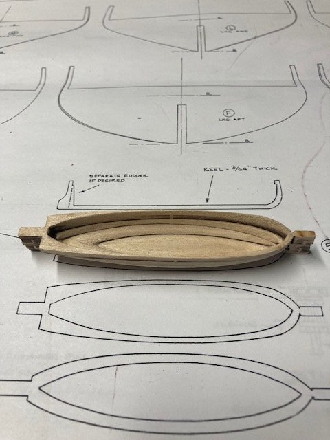
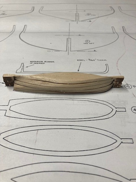
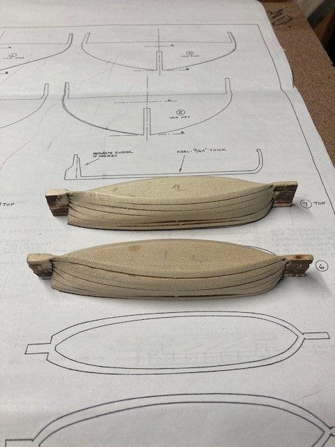
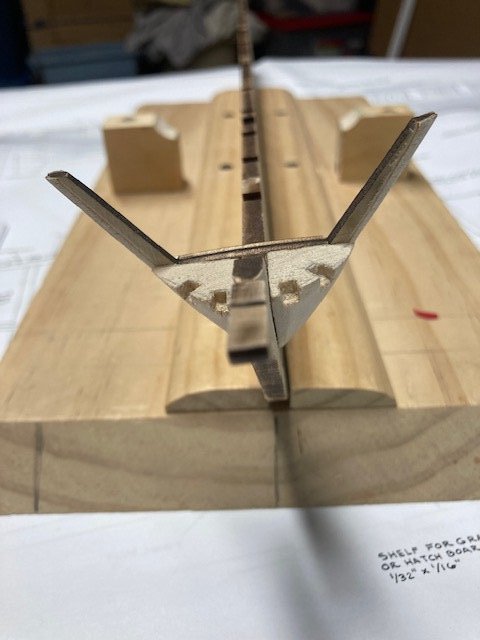
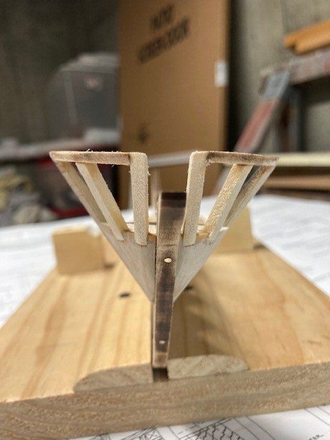
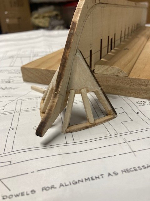
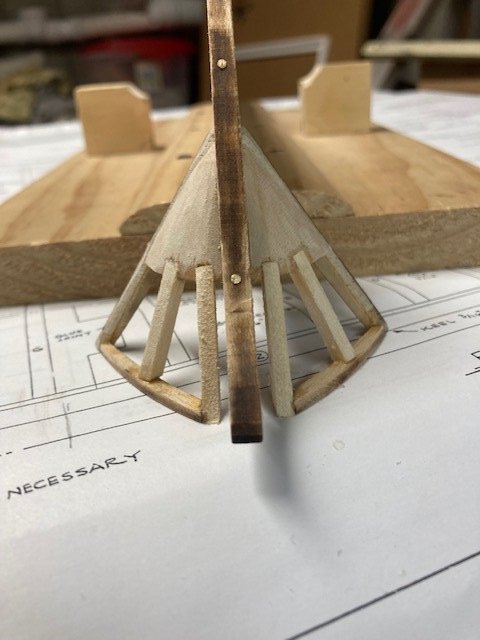
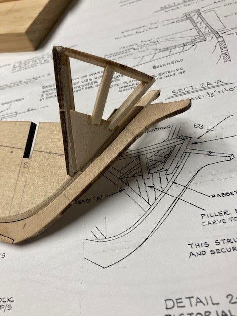
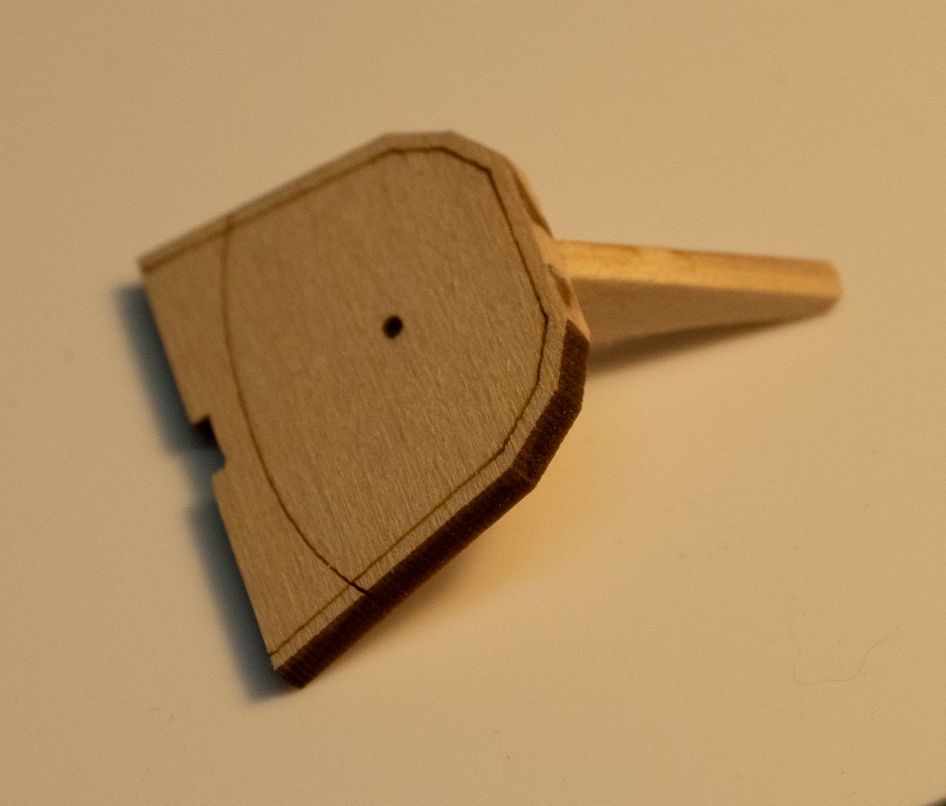
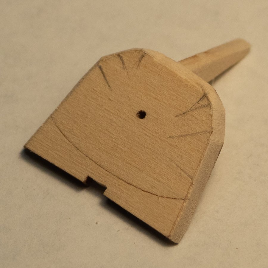
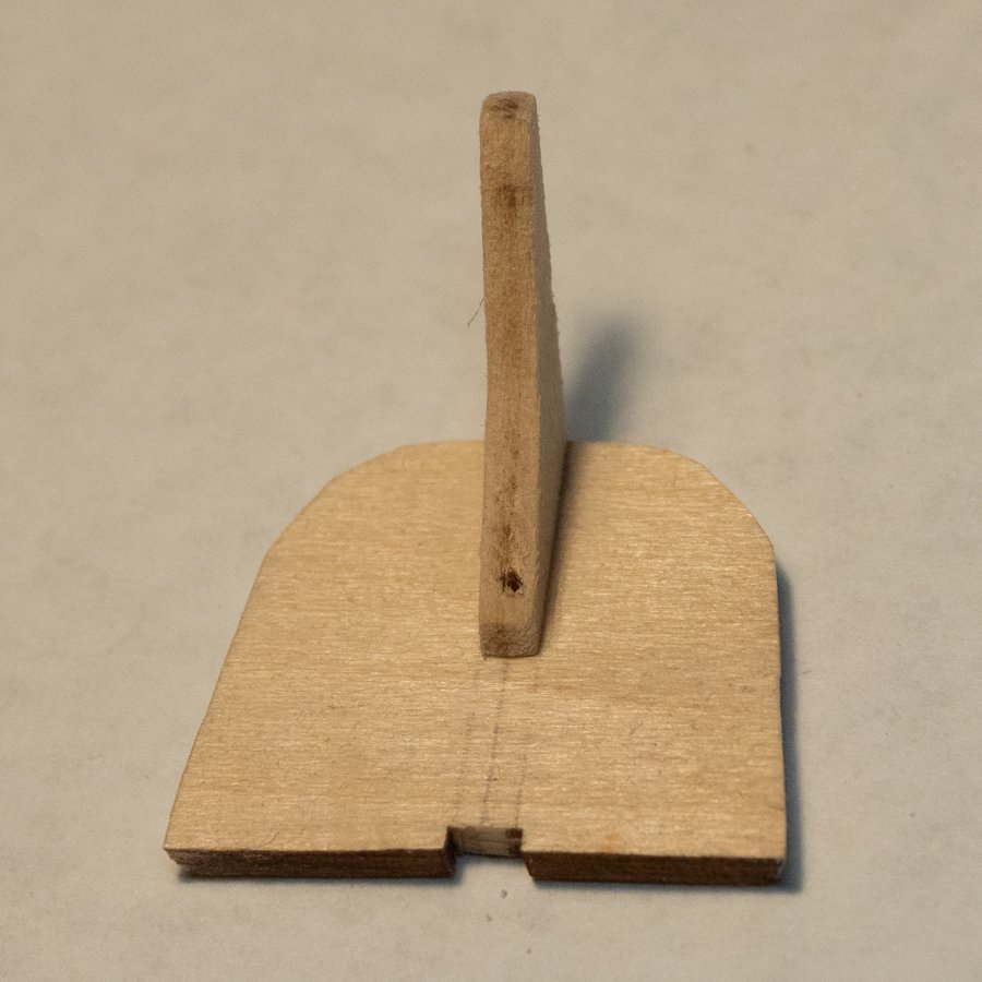
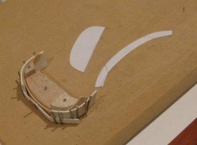
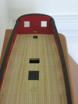
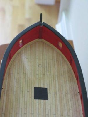
 Here we go with the Norwegian Pram by Model Shipways. The first several steps cover both the bow and stern transoms and knees, and go back and forth between the two. I am going to do one transom at a time so I can keep my parts straight, bow first. I cut out the knee and sanded off the char. Then I cut out the bow transom from the parts board and sanded/filed the necessary spots. The next step was to draw a midline, then draw two more lines the width of the knee apart. After struggling with the small transom and a pencil and a ruler, I realized that it would be a lot easier to draw these lines onto the transom while it was still in the parts board. I tried this with the spare transom, and it worked great. It's helpful to extended the lines past the laser lines to use them as sight lines when gluing the knee. After drawing the lines, I cut the transom out of the board, sanded the extra "connection" bits, then put it back in the board. I glued the knee to the transom, using the extended lines on the parts board to line it up. The picture in the instructions show the appearance of the knee when it's glued, and that indicates which of the "legs" of the knee to glue to the transom (the shorter one). Ignoring the stern transom instructions, I went to step 3, finishing the bow transom. Bevel each facet as flat as possible, removing the char, and using the far edge and the marked bevel line as your guides. I took a little too much off where the knee meets the transom, but the rest looks pretty good. I found it hard to make the straight-ish lines of the contour as shown in the instructions. Drilling the hole through the transom and the knee: my pin vise drill bits aren't marked (which one is #55?), so I selected the one that fit in the hole in the transom. I put tape around the knee to help prevent tear-out, after seeing in another build log that tear-out was a potential issue. I went really slowly, and it came out pretty well, although the hole is just a touch off center in the knee. Next: returning to the start of the instructions to follow the stern transom steps.
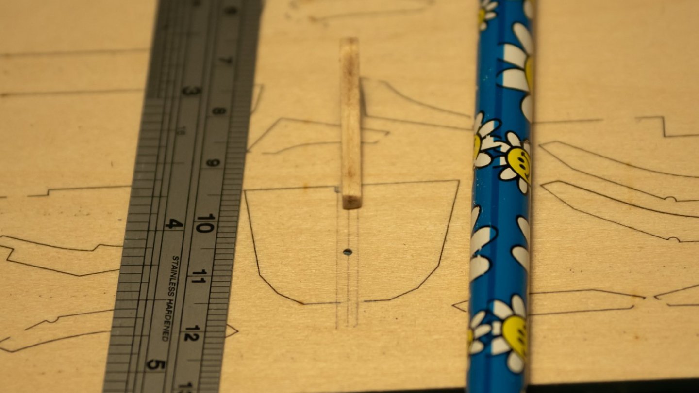

-
At long last I have started my CWM. This kit has been in my stash for quite some time. I saw no point in photographing the kit contents as there are quite a few Morgan build logs showing the parts. I will note that, contrary to the instructions, the center keel was a single laser cut piece, not 2 pieces. I do not know if this is still the case, but it makes for an easier start to the build. The photo shows my building slip set up to start test-fitting the bulkheads.
- 294 replies
-
- 9
-
-
- charles w morgan
- model shipways
- (and 1 more)
-
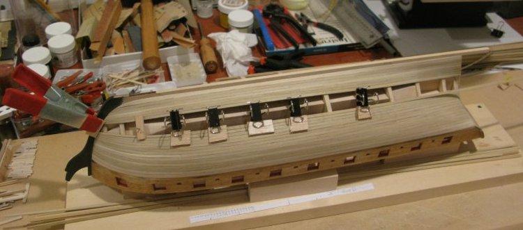
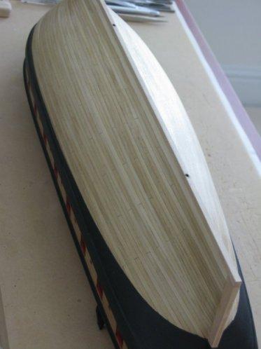
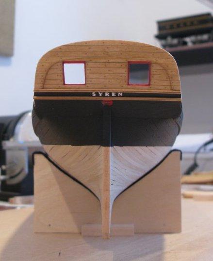
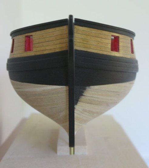
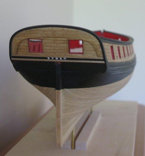
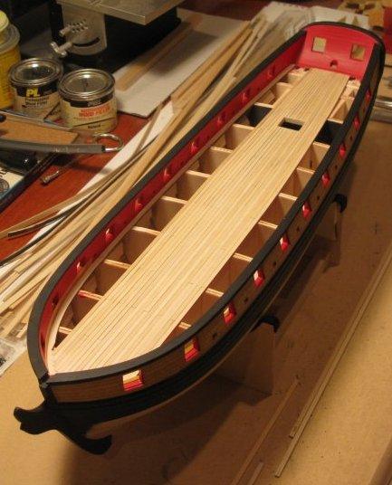
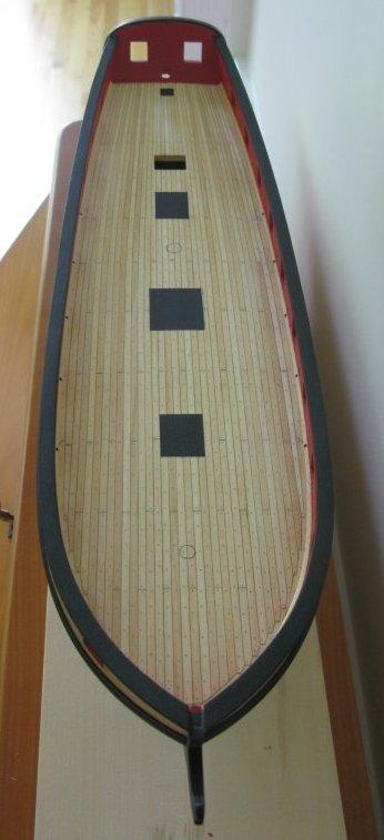
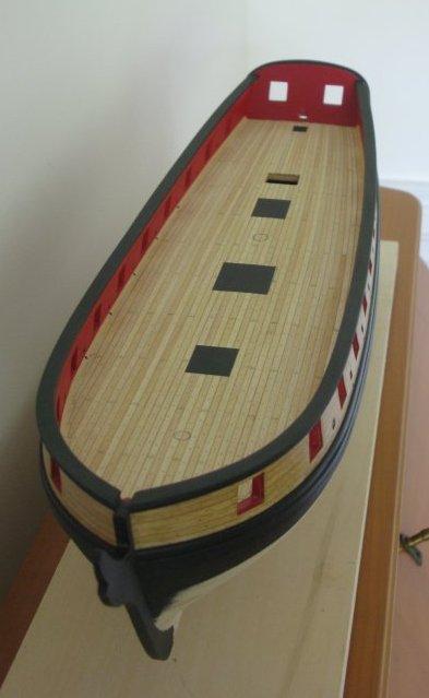
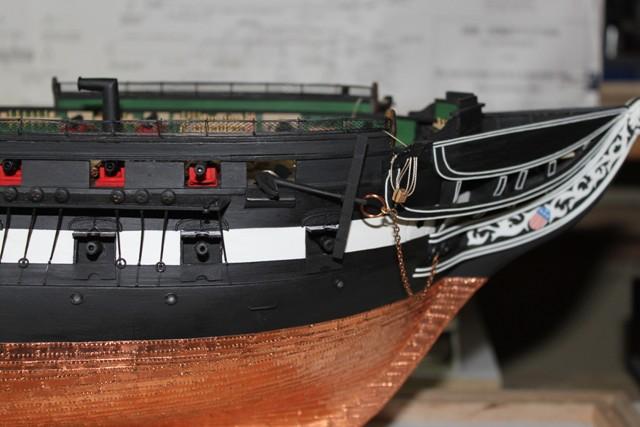
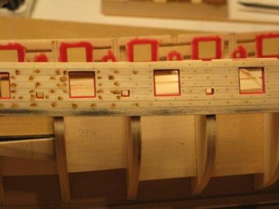
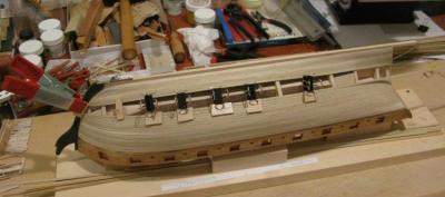
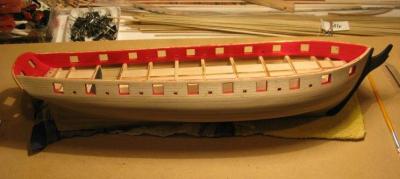
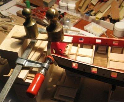
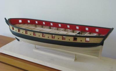
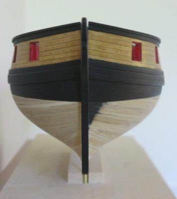
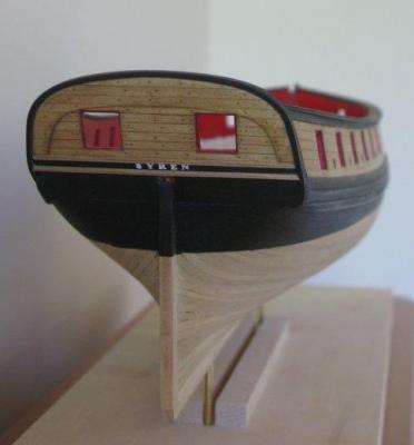
 Hi, my name is Thomas Gahm. My build log disappeared as so many others during the recent crash, and I just try to reconstruct as much as I can. Bulkheads and filler blocks are being glued in place. Gun ports are framed and the fairing of bulkheads is finished. Planking of the upper part of the hull with bass wood strips. The strips were selected for homogeneous color and texture. Treenailing using the wood filler based method described by Chuck in the instruction book. During my last ship model build (Anfora kit Ictineo II) the combination of the applied wood stain and the slight fuzziness of the treenail hole edges led to a larger treenail appearance than initially intended. To avoid this effect I drilled holes which were slightly smaller than the intended treenail size of 0.5mm and I opened them up with a needle of a slightly larger diameter (0.53mm). This led to well defined, round holes with sharp edges, which once filled with wood filler gave me the intended treenailing effect. Planking of the lower hull with bass wood strips. As this part of the hull will be covered later by copper sheaths I did not particularly select the wood strips for texture or color. Finished hull planking. Lower part of hull planking. Two brass pipes were buried in the keel to allow for the possibility to mount the model later via two brass carriers inserted in these pipes. If these mounts should not be needed the holes can be covered up via the false keel. Stern view of the Syren. Mounting the Syren name turned out to be a bit tricky due to the small size of the photo etched letters. The following method worked for me: I painted the letters (white) while they were still attached to the photo etch grid. After separating them from the brass grid I arranged them to form the name “SYREN” on a sticky tape mounted on a flat piece of wood with the sticky side up. Once I was satisfied with the arrangement of the letters I covered them with a second piece of transparent tape with the sticky side towards the letters. After turning the whole arrangement upside down so that the first tape was on top and the second tape underneath the letters I removed the first tape while carefully making sure that the letters did not come loose from the second tape. Now all that remained to do was to apply some superglue to the uncovered letter backs and transfer the name as a whole in its final arrangement to its destination on the stern. The use of a transparent tape allowed for precise positioning. Once the letters were glued to the hull the tape could be removed. Building of the stern transom. To form the stern transom I modeled it first with a piece of paper which I then used to cut out the wooden (bass wood) counterpart. This was then soaked in hot water and bent to its final shape in a jig. The formed transom is glued in place. Finished transom. Front view of the Syren. The planks are stained with a mixture of 1 part Minwax Golden Oak and 2 parts Minwax Natural wood stain. Stern view of the Syren. Planking of the deck using selected basswood strips. The planks were tapered towards the stern. Finished deck planking with waterways. I painted the locations of the future gratings black to prevent the possibility of the deck planking to be seen through the openings of the gratings. The deck was stained with Minwax Natural wood stain. Stern view of the deck with treenailing. Plank nibbing. Deck view.


-
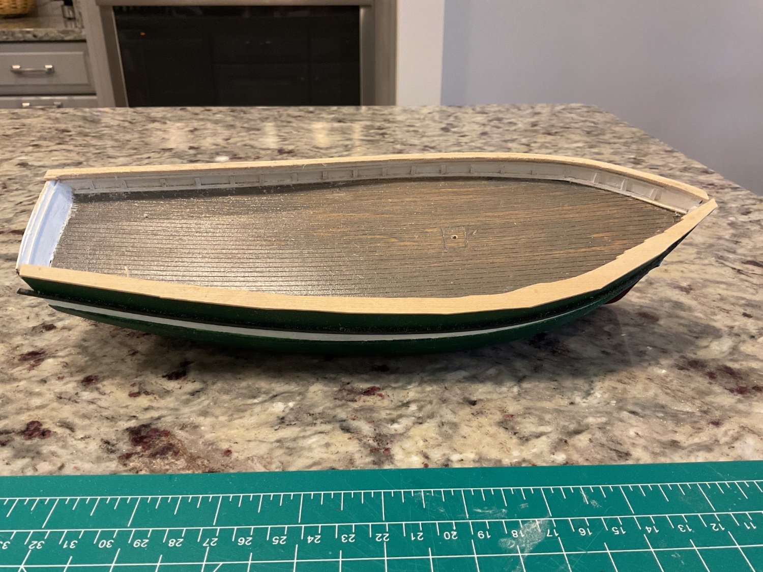
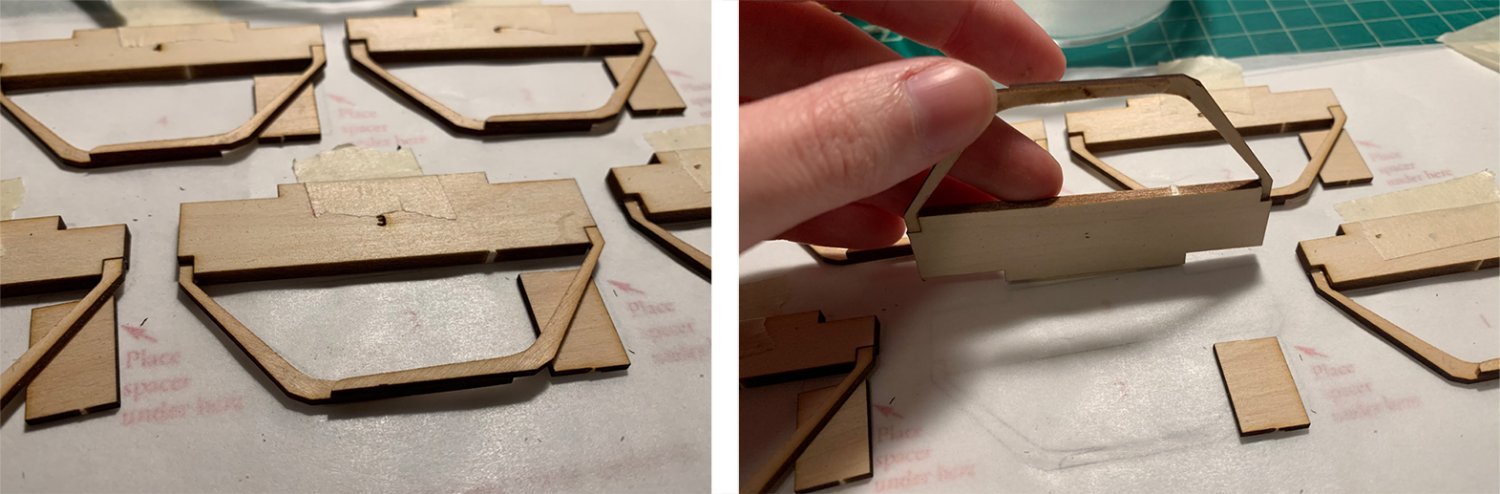
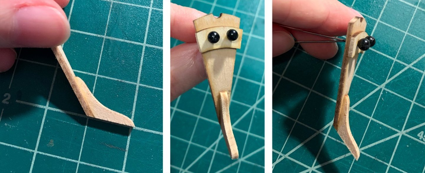
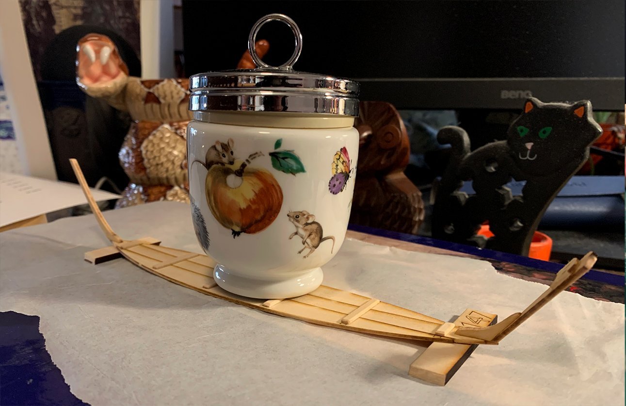
 My first build! As exciting as it is intimidating. After staring at the box for a bit, getting over my nerves, I cracked my knuckles and cracked open the lid. Step one admittedly wasn’t photogenic—I made sure all the pieces were present, gave the full instructions a careful read, and then poured over multiple build logs. The next day, the real fun began. I opted to build the bottom from scratch rather than use the pre-made piece. This meant cutting, gluing, and sanding—so much sanding. I was skeptical at first, but low and behold, the instruction’s tip about moving the piece rather than the paper worked. Instead of a sanding stick, I opted to just tape some sandpaper flat to my working surface. A great decision for these long, straight pieces! Not so great for others. (More on that later.) Hoping to spare my fictional sailor a tumble into a sharp corner, I studiously over-sanded the edges of my cleats. The instructions spoke about removing edges to prevent injuries—but…what about the thole pins? They make sense to have, but I can’t help but think they’re a stab wound waiting to happen. A poor fate for a clumsy sailor… When sizing the cleats, I ignored the length of the burnt guidelines. Instead, I followed what other builders had done and made sure each one had some breathing room before the edge. After sanding and gluing the stem without incident, the transom gave me pause. I decided to go a little off-book, sanding it and the stern knee together before attaching the stern cleat. It seemed to me like a choice between vigorously sanding three freshly glued, breakable parts or two. (I opted for two.) I’m really proud of how it turned out! After adding glue to the transom and plopping the stern cleat on, I strung the two together with sewing pins. This let me squish the pieces together without fear of misalignment or gluing the holes shut. It also made it a million times easier to brush away excess glue. A simple strategy, but very effective. Should the edges of the stern cleat be softened as well, for our clumsy sailor? The instructions didn’t mention it so I refrained, but I feared once again for his poor noggin. After that, I was humbled. I spent far, far too long attaching the pieces to the bottom. I thought about it, researched it, did it, fussed with it so much the glue gave up, then had to do it all over again. I just couldn’t decide on the alignment. Should I follow the burnt template line, allowing a bunch of the stern knee to hang over the edge? Should I keep the point of the base and the outside of the transom lined up? Other build logs seemed to differ, and I couldn’t find many clear shots from the side to compare. I’ll upload pictures of mine. If it turns out I made a bad choice, others will know what not to do. If it works out—whew! One of the things I’ve enjoyed most about these dory build logs has been seeing what random things people scrounge up to use as weights. For mine, I made use of an egg cup my grandfather gave me. The whole kit and caboodle was set aside to dry, with a few other rejected weights keeping watch behind it. Onto the frames! I’ve seen many people comment on the template being the wrong size. I actually found it to be exactly 1:1—which makes me think I’m either lucky or doing something wrong. A few things I found helpful: I taped a sheet of parchment paper over the template to avoid gluing the paper. I numbered and labelled each left and right piece in pencil before cutting them free. This saved me almost immediately when I cut out and sanded a “2R” instead of a “3R”. It occurred to me I could have used this labelling as an opportunity to practice “port” and “starboard”. Then I realized I’d be adding additional challenges to an already daunting project. Left and right it was. A note to myself for next time: this worked great, but the pencil was difficult to erase before gluing. I’d write lighter next time. I prepped the frames one at a time but held off on gluing. The process: pick a number, label the two frame pieces, cut them out, sand them down with a scrap of sandpaper, then dry assemble it on the template. Once all of the frames were sitting primly in place, I could go through and glue them all at once. Since the glue dries so fast on my palette, I found this more economical (and it saved me some brush washing). I taped down the crosspieces. I’m so thankful I taped down the crosspieces! It meant I could easily lift the whole thing upward to clean the excess glue beneath, then settle everything right back into place. Free spacers were helpful to tap the freshly glued bottoms against, ensuring they were flat. This stage was when I really started feeling my lack of a sanding stick. I’ve got an old wrist injury, and it was starting to complain. So were my fingers, which had been slowly filed down alongside my pieces. Ah well. Funny how every tip I followed treated me well, and I regret skipping the one I didn’t. Almost like I should listen to the experts… After gluing up the frames, I checked the status of my now-dry boat bottom and found it lacking. Out came the water again, and a book was added to the weight mix. That’ll show it. I seriously debated continuing, but as I’d just spent half the day squished up at my table, a break seemed in order. I’ve got the itch now! But planking is intimidating. A problem for later…after my new sanding stick dries. 😄


- 9 replies
-
- 12
-
-
- Lowell Grand Banks Dory
- Model Shipways
- (and 1 more)
-
 I am restarting my build log. I had to suspend construction in 2019 for various reasons, 2 knee surgeries, covid, etc., etc. I don't know how to or if my old build is still available, but let's start from here. Hull is completed and painted. I built the deck with nibbing strakes. Starting on cannons. Pictures will follow (Iphone not cooperating today). PS: I build at a slow pace so posts will not be regular. I got a plaque from NRG stating "Tain't a hobby if you got to hurry" and that is my motto.
 -
 I started this boat last Fall before I was a member here so I’m actually somewhere in the neighborhood of 80% finished. It's my first nautical build so what might appear to be lightning fast construction is really just a lot of catching up on already completed steps. When I get to the stuff I’m doing now you’ll notice a rather dramatic slow-down! My photos of the early stages of the build are hit and miss and the quality leaves a lot to be desired. It's casual documentation at best. Fortunately, lots of good logs for this boat are already available on this forum so all the nitty-gritty of actual construction techniques have been covered quite thoroughly by far more accomplished builders than I. While this build log certainly isn’t necessary in terms of critical new information, I thought it would be a good opportunity to get familiar with actively using the forum and share some of the things I did differently on my build. My next build log (1:32 Amati Fifie) will be a much more professional endeavor with photos from my “real” camera rather than a phone…I promise! Thoughts on the kit: If you plan to build this kit entirely from what’s in the box, you should be able to get reasonably good results. My kit was missing a few items but nothing I couldn’t make myself so I didn’t pursue replacements. Other than the planks and building jig, I didn’t use much of the die-cut material provided in the kit. Given that I was looking for a little more “texture” out of my weathered boat than the smooth basswood the kit provided, I turned to my bottomless supply of scraps from various projects I’ve done over the years. I wasn’t overly excited about the look of the rope that came with the kit given what an important part of the overall visual impact it has on a boat of this scale (or any scale really) so I opted for the excellent stuff available from Syren Ship Models instead. It’s a dramatic improvement for such a small investment. This kit comes with 6 sheets of what I consider clear/excellent plans and Ronnberg’s book “To Build a Whaleboat” which is half instruction manual and half a history of the whaleboat in general. For me, these items alone are worth the cost of the kit. I was a little surprised that Model Shipways used such a crudely built version of the boat on the box cover. It doesn't come close to accurately representing the quality of the kit and really would have made me think twice about my purchase if I had seen it in person. Your results will most definitely be far better than what you see on the box! 6 sheets of wonderfully detailed plans. Ronnberg's excellent instruction book. The building jig: If I had any advice to offer on this build as a boat/ship modeling novice, it would be to take your time on this particular step. It’s tempting to hurry through setting up your building jig and getting on to the fun part but everything that follows depends on accuracy here. My kit had quite a few small and not-so-small discrepancies between the plans and the laser cut parts so be sure to compare the two and proceed accordingly. Trust the plans rather than the die-cuts. If I had assembled the building jig “as-is” it clearly would have caused issues during planking. This is probably a no-brainer for people with a few builds under their belt but I was a little perplexed as to why the die-cuts wouldn’t be dead-on. I know better now. I would also recommend strengthening the building jig if the slotted joints feel sloppy/loose like they did with my kit. I added small blocks to strengthen and align the joints overall and I think it was worth the minimal effort invested. I may have just gotten a little unlucky with my particular kit but I suspect this is a common issue. The final thing worth noting as it pertains to the jig is investing in a good quality piece of flat material for your building board that’s not likely to deform with changes in humidity. Dead flat and staying that way is a must if you want the bow and stern horses to sit properly and receive the frames without modifications. The frame after it had been removed from the horses. Note the use of small blocks to square up and stabilize things. The planking process puts a lot of stress on this thing so sturdy is good.
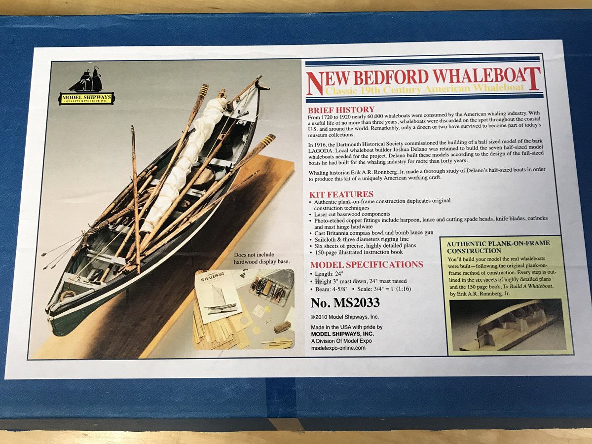
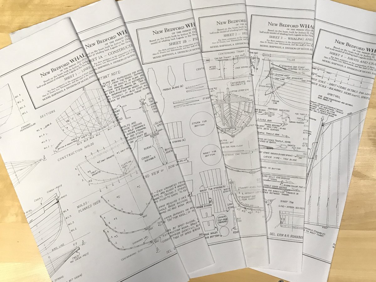
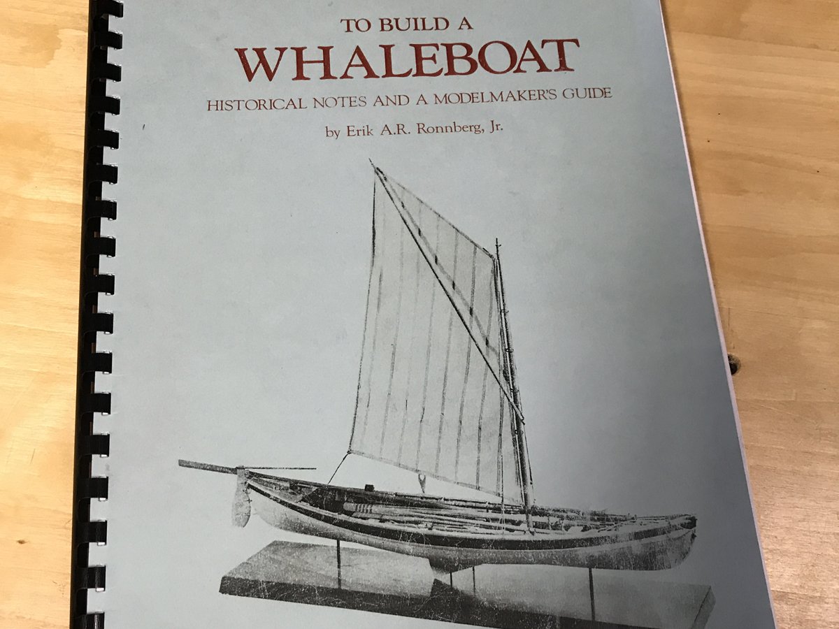
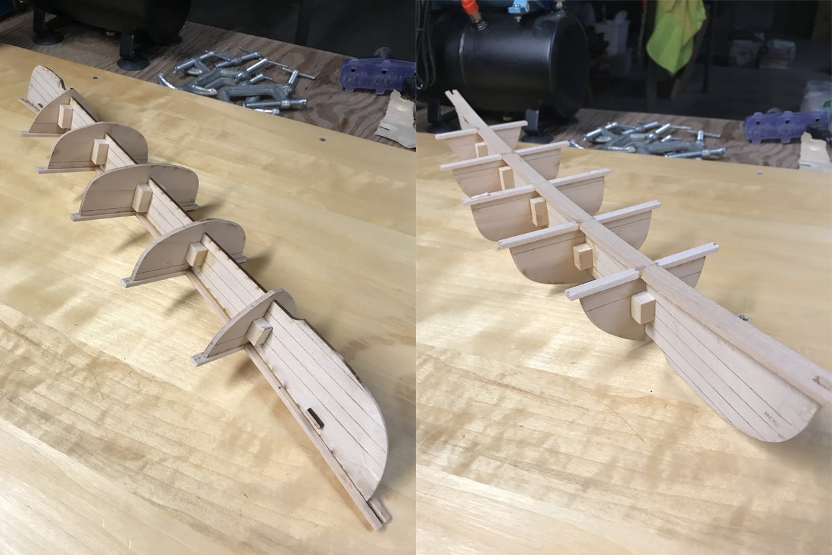
- 52 replies
-
- 3
-
-
- model shipways
- new bedford whaleboat
- (and 1 more)
-
 I expected to be now concentrating on my Agamemnon, but it seems the ship modelling gods had something else in store for me. I have been asked by someone to build a Mayflower for them. This is not a model that I would have chosen for myself, as I'm not particularly interested in 17th century vessels. My favourites are late 18th century. Nevertheless I'm happy enough to build it for someone else. Keeps me off the streets. There are several Mayflowers available, but I settled on the Model Shipways version, as I tend to like their kits generally and Chuck Passaro designed this one, so it seemed to me to be the best option. I don't tend to complain too much about cast metal parts. Usually I find they can be made to be acceptable with a little filing, paint etc. But I don't think I've ever seen anything as bad as these cast metal crow's nests that came with the kit. In the instructions, it shows wooden components which appear to be quite acceptable and which I assume is how the kit originally shipped. However, I was surprised by what I found which look like something my grandmother would have baked tarts in. These just won't do. Not only do they look horrendous, but I don't know how I would be able to use them. It's difficult to see in the picture, but there is almost no lip or overhang on the upper rim, yet it's necessary to mount deadeyes and futtock shrouds. I just don't see how I could do that. Also, much of this ship has a natural finish, so painting these things to blend in would be almost impossible. So rather than starting at the beginning, I decided to get this problem behind me first and I set out to design and build something that I could live with. Here is what I have come up with: I simplified them slightly. The plans show 16 brackets of about 1/32" wide. I was having quite a bit of trouble with that, so I reduced the number to 12 and made them 1/16" and I found that worked better for me and still looks ok. The crow's nests on the replica Mayflower II have closed sides, and I believe it was the idea for this model too. However, I'm going to leave them open. I experimented with closing them in and wasn't happy with the look. Also, all of the other kit versions of the Mayflower have open sides, as do many other ships of this period. There isn't a lot of glue surface on the upper ring and there's going to be a bit of tension on it, so I added four pieces of brass rod that run through to the bottom, which should give it a bit more structural integrity. You can see one of them in the picture above, but I don't think they will show up when all the bits and pieces are in place. So, now I can relax, knowing that I have that little problem solved and go back to the beginning. David
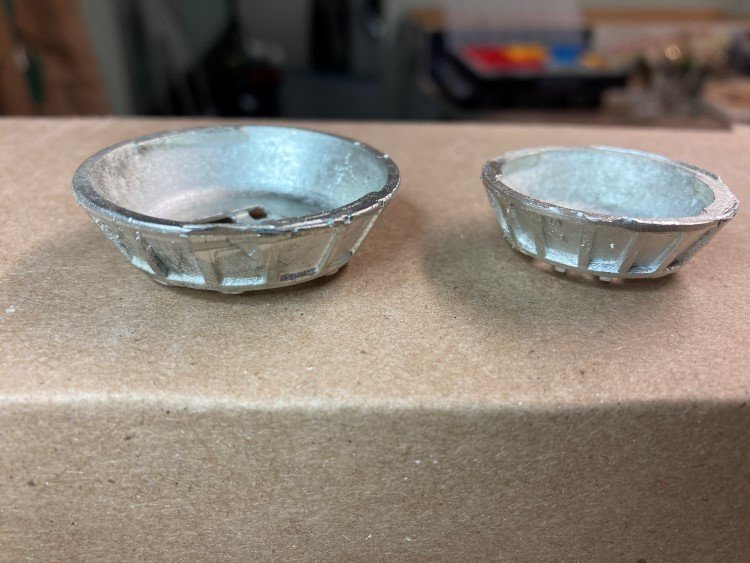
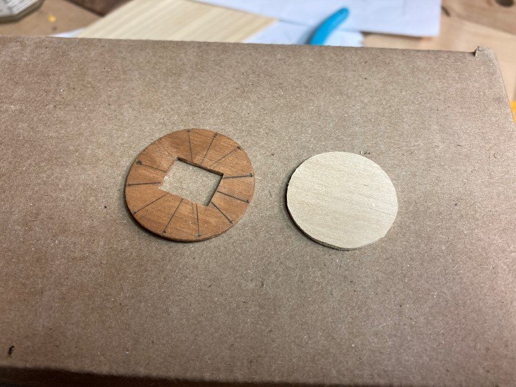
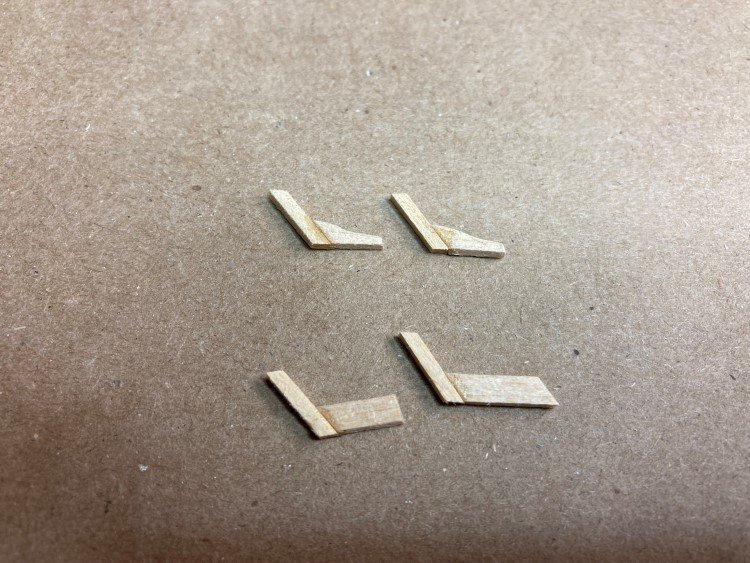
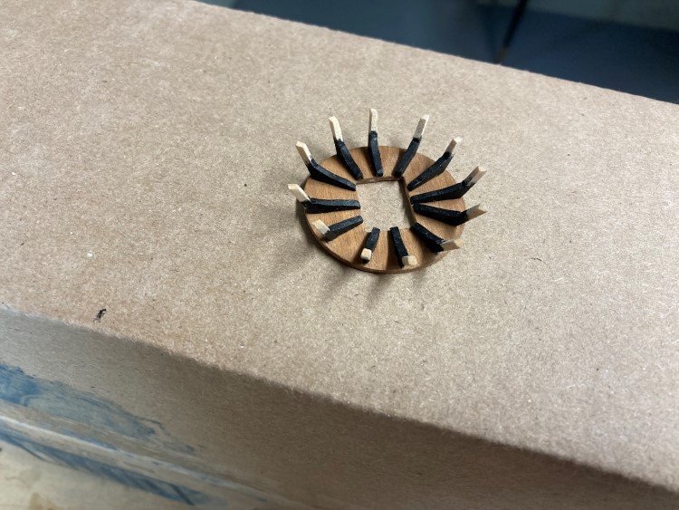
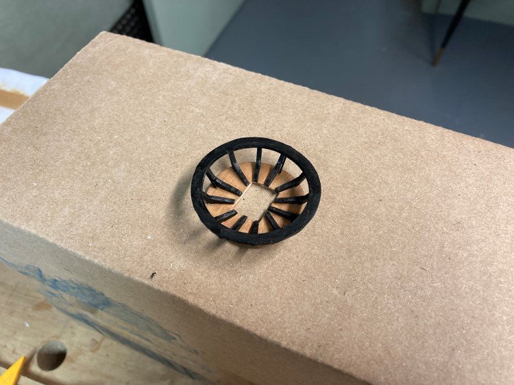
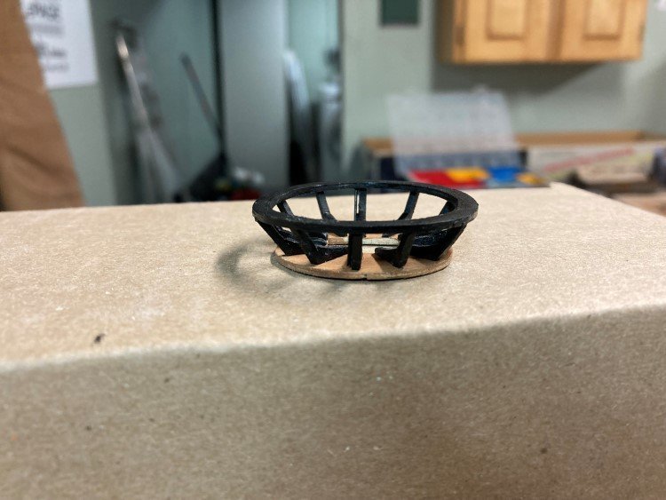
- 43 replies
-
- 13
-
-

-
- Mayflower
- Model Shipways
- (and 1 more)
-
 I'm starting this build log on the Mayflower from Model Shipways. I'm pretty new to this kind of modelling, so I'm hoping for as much advice and constructive criticism as I can get. The first thing that they want you to do is cut out the false keel and gently sand off the laser char. Then, you glue a piece of basswood called a 'rabbet strip' along the bottom edge and along the stern. This allows you sand or chisel the bottom rearmost part of the keel from its original 3/16" thickness to 3/32" below a predetermined mark called the 'bearding line', which is laser drawn on one side of the keel. (As the rabbet strip is 1/8" wide, it needs to be reduced to 3/32", which means that 1/64" is removed from each side. I first cut the rabbet strip down to about 3/32" in the area that need it, and then used a diamond dusted file to thin the keel as necessary. You can see this in the second picture, where the lighter colored rabbet strip is along the bottom of the keel, and the plywood has been thinned in the bottom left corner, thereby changing its color as the top layer was filed away.) I think that part went fine. But, I do have this question. I've taken a picture of the piece of plywood that the false keel was taken from, and then I've included a picture of both its long and short edges. Both of them have pretty noticeable warpage; and when I put the false keel onto a flat surface as it is in the second picture, there's about 2-3 mm of vault in the center. I've soaked it and left it to dry under some weights a couple of times, and it initially looks pretty flat, but after a few hours, it's back to the same warp. My understanding is that it's pretty important that the keel be straight in order to proceed effectively. I believe that I have a few choices: 1) keep soaking the keel, and drying it under weight on a flat surface, and hopefully it eventually will flatten out. 2) proceed with gluing on the bulkheads, and then put wood spacers between some of the bulkheads in order to force the keel straighter. 3) I read somewhere on this forum that you can multiply score one side of the keel, and then brush glue deep into the score marks, and clamp it between glass until it dries. Sounds complicated... 4) get a replacement part from Model Shipways. (I've heard that they have pretty good customer service.) I don't think that this is necessary, but I'll defer to the wisdom of the forum. Also, the plywood that contains the bulkheads is similarly warped. These are much smaller pieces, so the warping isn't as obvious as it is on the keel, but it is definitely there. (I've included a picture of one of the bulkheads with my finger holding down one side, showing that the other side lifts off the table.) Should I be worried about those too? Any suggestions?
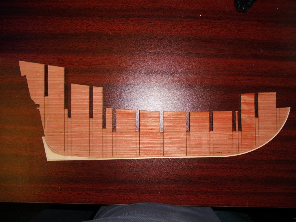


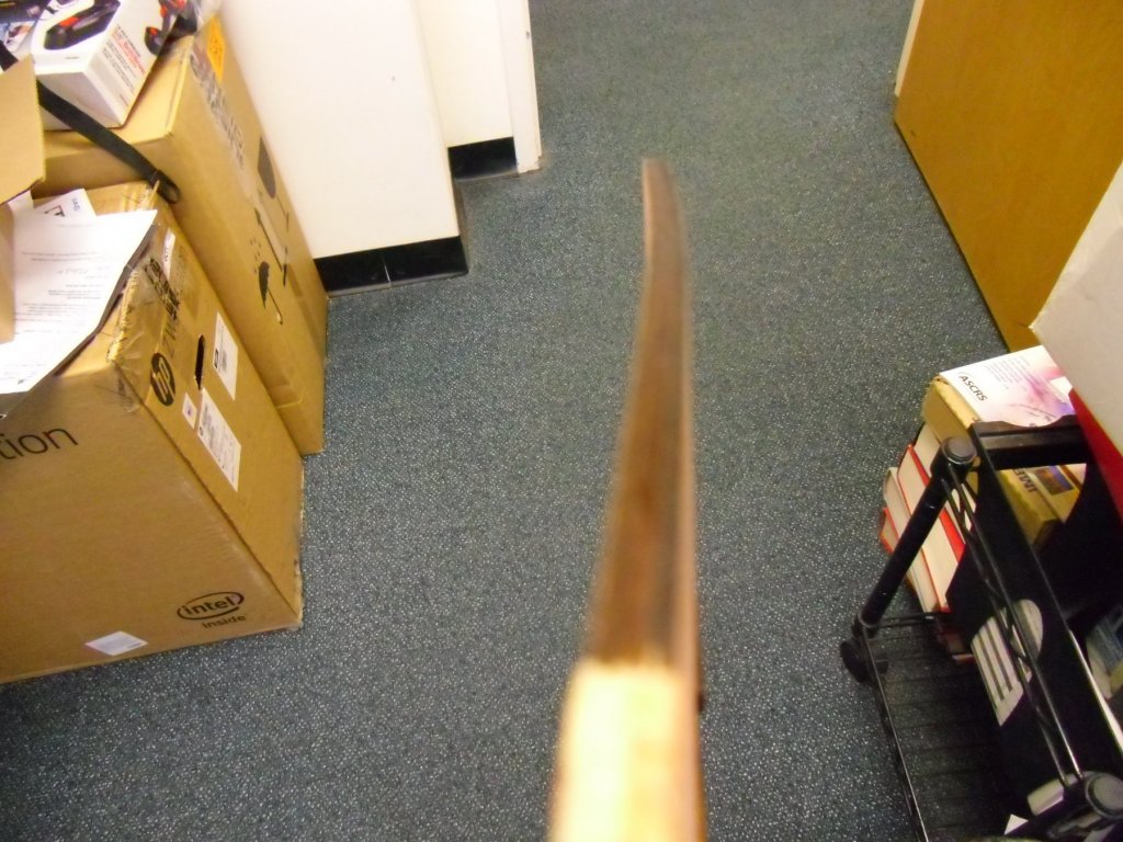

-
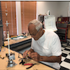 I decide to build the Syren after reading Chuck Passaro's instructions and Gahm, dubz and augie's build logs. The work done on these build is truly amazing and I'll be using them to guide me with my build. It has taken me a year to get up the nerve to enter a build log, so here goes please bear with me. 😁 on June 28th I received the kit so as seems to be a convention here's a photo of the box.
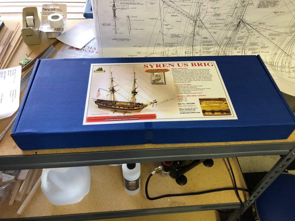
-
 I decided to post a build log for this model. I'm somewhat new to model ship building and modeling in general but I've completed three Model Shipways shipwright series with....okay results. The Dory, the Norwegian sailing pram and the lobster smack. What an awesome idea for newbies! I'm really glad I started with these models as I've learnt so many valuable skills (and made many educational mistakes). (Do they purposely make the models and instructions imperfect so we learn to overcome issues??) I was dreading the rigging on the lobster smack but found a couple of techniques on YouTube and came up with a couple of my own and I'm happier with the results. Still toying with redoing the halyards. Mods, please let me know if I'm not supposed to post my finished models here and l'll remove the pics. I was proud of each as I finished it. The Bounty Launch was a gift and, reading about it's history, I'm pretty interested! Amazing journey that I'll be reading more about. The kit is a bit different from what I'm used to. The instructions are more abbreviated and there are 4 GIANT pages of blueprints that have much useful information on them. After getting more familiar with the format, I love it! I've built the keel etc and am starting to build the molds. I have 3 concerns right off the bat: 1) they suggest staining the interior. Really? I thought staining was a recipe for blotchiness. I kinda count on paint to cover my mistakes. I'll have to decide if I'll stain or paint soon. 2) My keel does not perfectly match the false keel. See Pic. The gap isn't as pronounced on the other side due to the laser etching. I'm considering regluing the keel and stem despite the fact that I've cut the rabbit. Any opinions are apreciated! 3) Some of the molds don't seem to be tall enough near the stern. I'd expect them to be slightly higher than the false keel so that when they're shaped, the lower edge matches the line of the false keel. Should I glue these higher so that the low edge matches the line of the false keel? Okay, I apologize for the order of the pictures. I'll figure out how to post properly eventually!
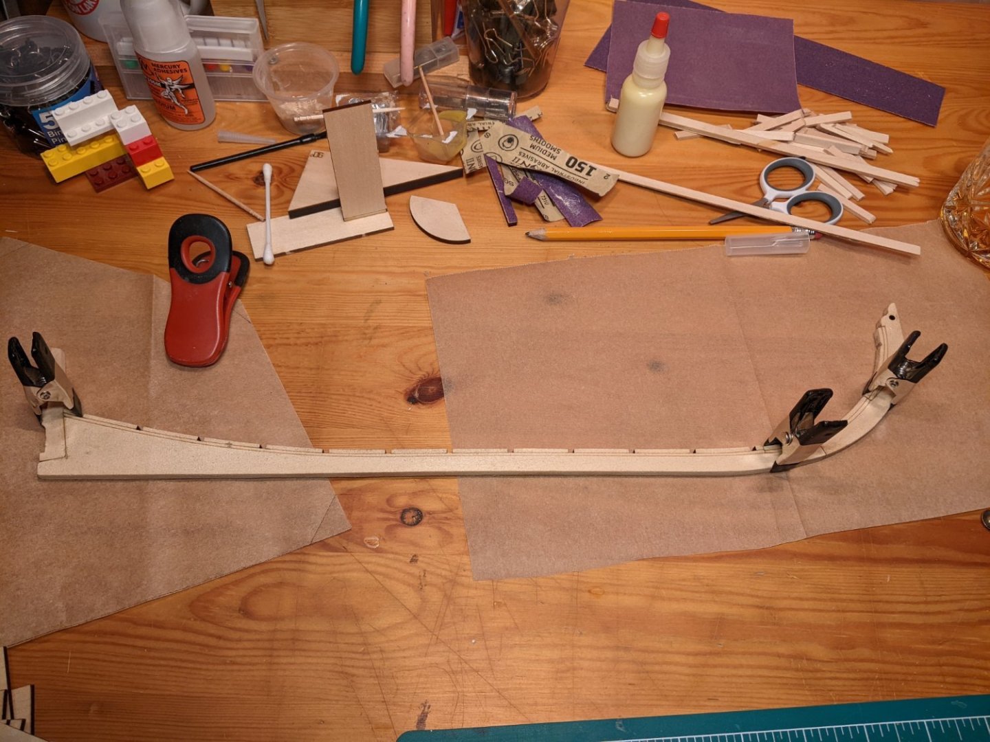
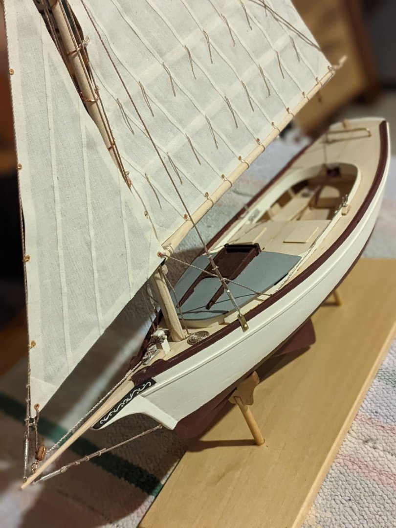
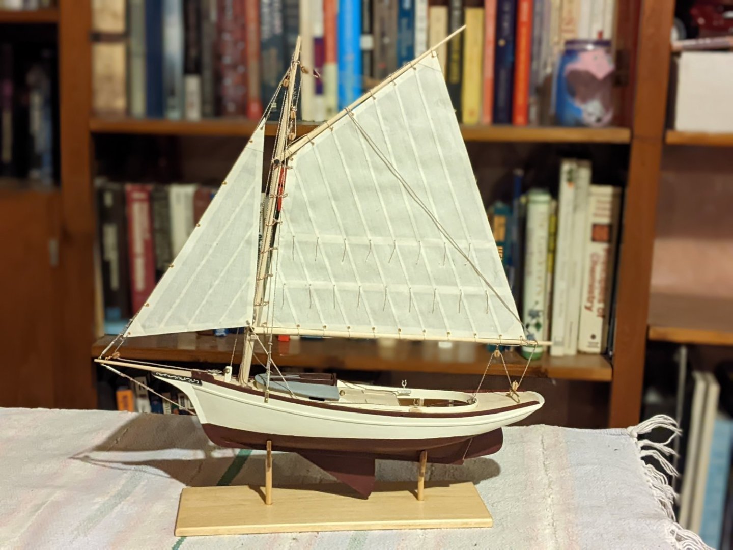

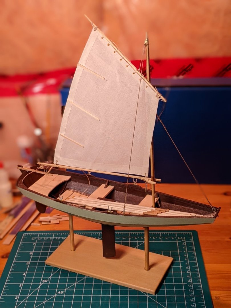

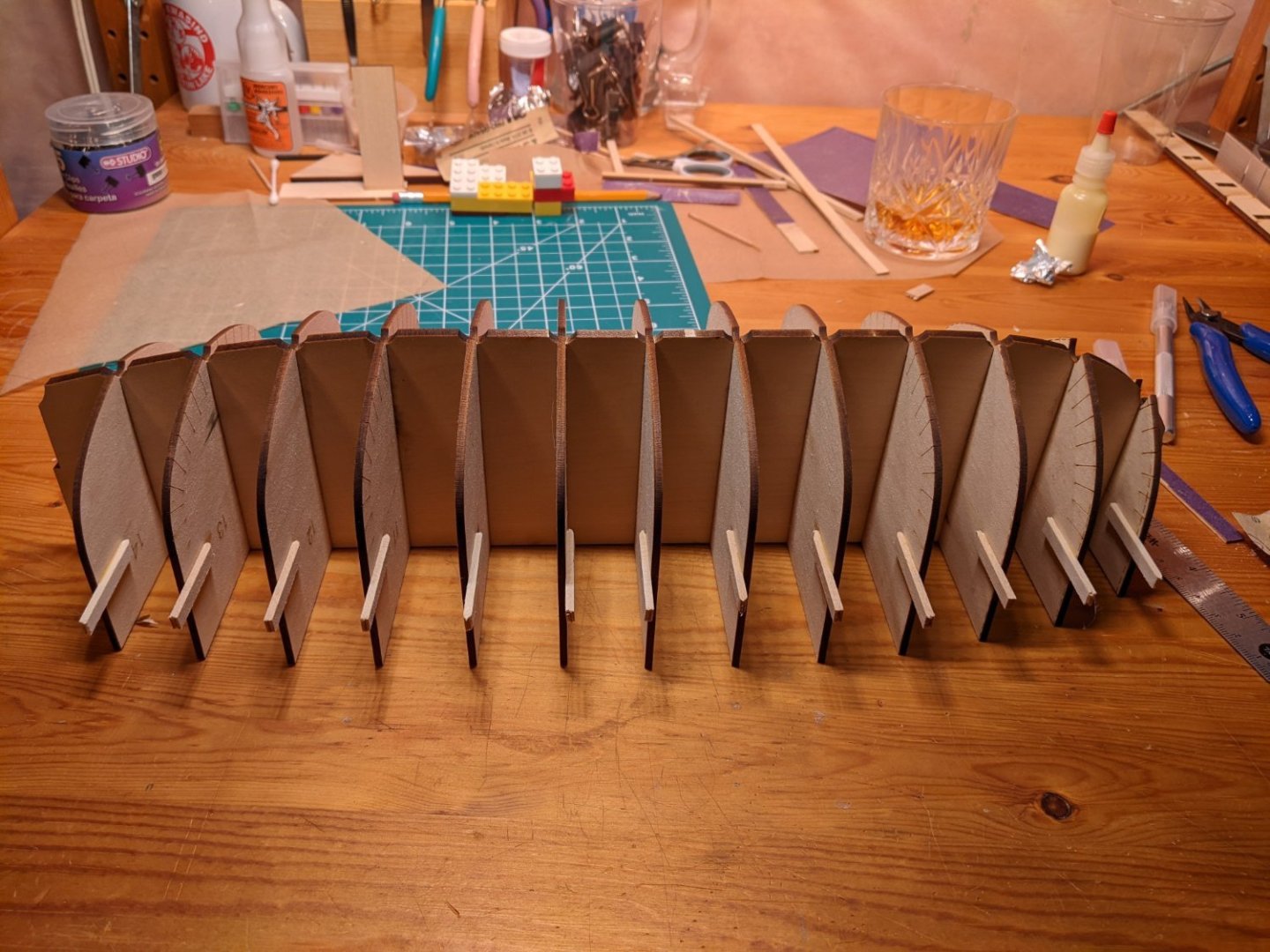

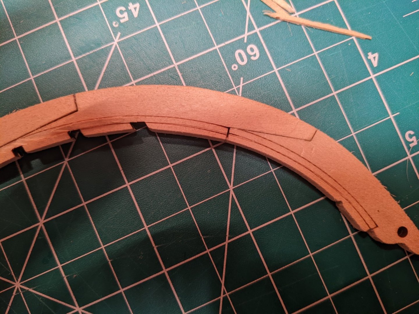
-
 While waiting for the HMS Speedwell project from Syren Ship Model Company I am building some smaller models to "fill in the spaces" in some of the cabinetry where the larger models will not fit.
 -
 This will be my first build and I welcome any comments, suggestions and questions. Living in a duplex that’s built on a slab we don’t have a basement and the garage isn’t heated, so I’m using a desk the spare bedroom. I’ve done what I can to protect the desktop and the carpet below the desk. Since we will be spending the next week enjoying our last camping trip of the season I won’t be able to start my build until the weekend of October 20th. But I do have my work area set up and spent 1 ½ hours doing the kit inventory. My plan is to explain my next step as I go along and then wait for feedback from more experienced model shipwrights before actually doing the work. When I return next week I will be cutting loose the 3 sections of the false keel, marking the reference line and bulkhead stations on both sides and assembling the false keel. Any suggestions on cutting loose the false keel sections without breaking / damaging anything? Any suggestions on the best way to transfer the reference line and bulkhead stations from the plan to the wood? Looking forward to starting my first build, Dave
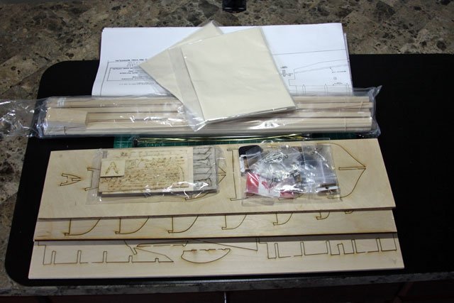
- 389 replies
-
- 8
-
-
- bluenose
- model shipways
- (and 1 more)