


thibaultron
-
Posts
2,670 -
Joined
-
Last visited
Content Type
Profiles
Forums
Gallery
Events
Posts posted by thibaultron
-
-
-
-
PART 3
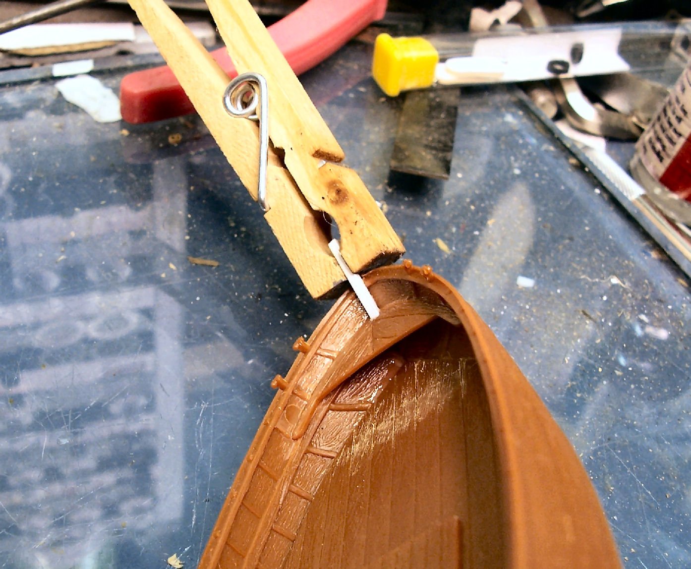
I started out by going out to wash down the hull, to get it ready for painting. While looking over it, I realized that I had forgotten a part. It is a loop that goes over the tiller handle, to limit the tiller throw.Not a big problem, at least until I tried to attach it!
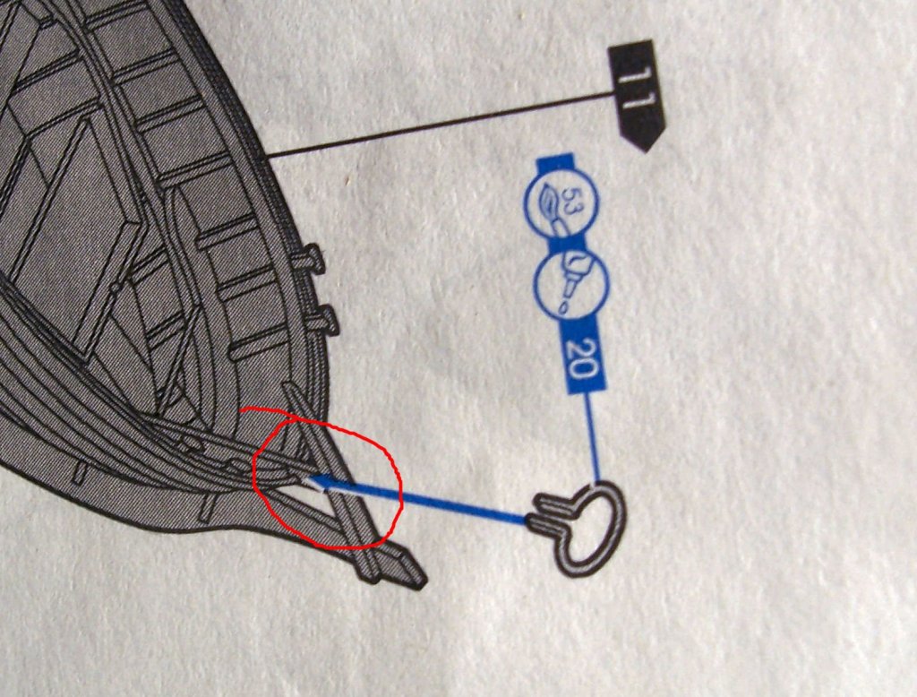
The picture in the instructions shows it being attached on the inner part of the stern timber. Alas, there is no “inner” part of the stern timber, on the model! The hull, as cast, has the stern timber, ending at the outside of the planking.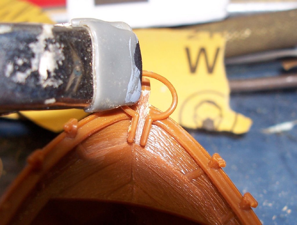
Above is the part held near the stern timber.
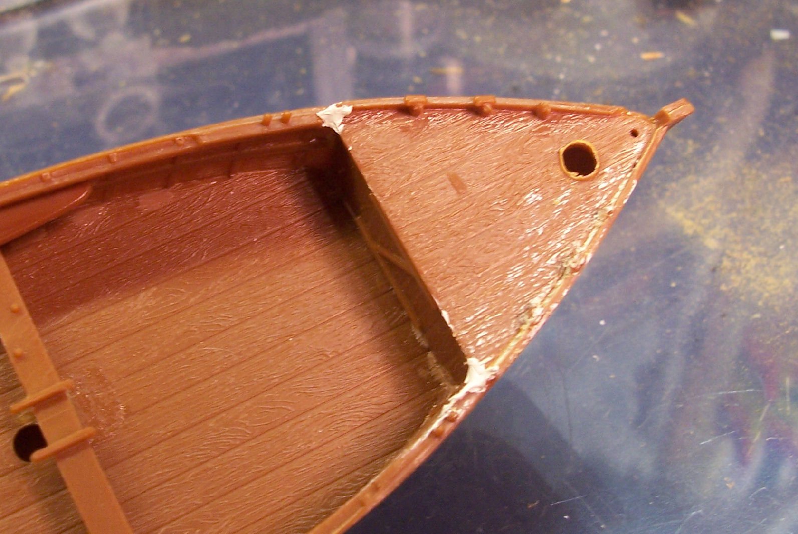
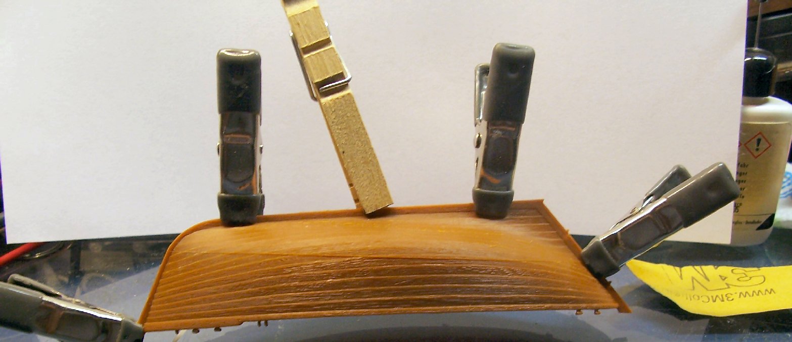
I cut a slot the width of the timber in the gunwale, and fabricated an inner piece from .060 styrene. The cast timber is actually .075”, but I only had the .060. Once I glue the loop on, you will not be able to see the difference.
I tapered the edge that sits against the hull (the lower edge in this photo), and cut it free. I left it over long, and trimmed it when the glue had dried. The photo below is out of focus, but you can see the part.

I decided not to try to fabricate an additional piece to fit between the stern seat and the deck, it would be all but invisible on the finished model.
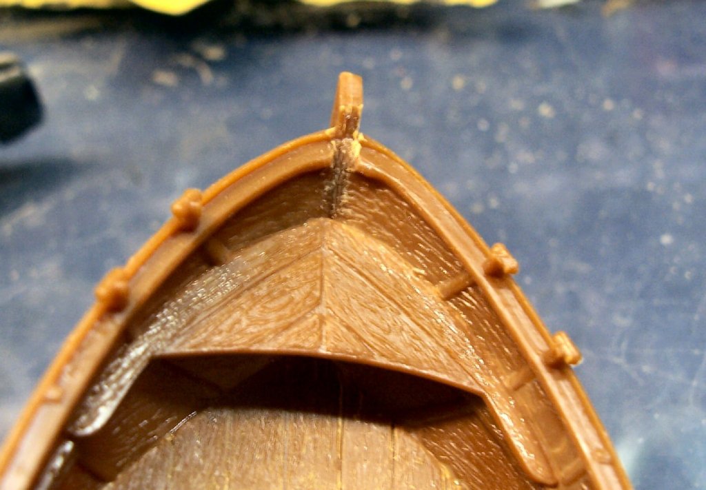
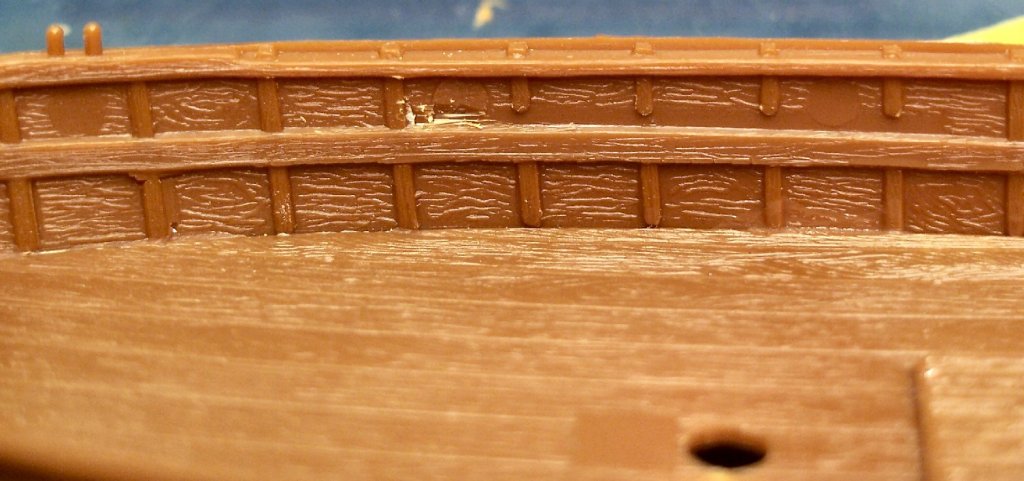
I also noticed that there is a gap between the foredeck and the gunwale, probably due to the sanding I did to center the mast hole. I filled it with putty, and will finish it up when it dries.

I can also see in the photo, that I need to remove the seam on the top of the gunwales and the stem, that I had not noticed before. Nothing like a nice closeup shot to shows you problems with you parts! 😊
-
-
Frank;
When I was developing the decal for the Carrie Price, I went to my local print house. The best printer they had had a resolution of only 600DPI, the same as my old color laser jet. This was not enough for my 1/64th print. I had an Epson NX430 ink jet printer that had a much higher resolution that did a better job. So check the print quality of your printer, it may be better than the commercial house printers. You can use photo paper, or make your own decals. Check Micro Mart or Hobby Lobby for the decal kits. Printing it on regular paper will cause bleeding of the color at the edges.
- druxey, popeye the sailor, Canute and 2 others
-
 5
5
-
-
Chuck; How were the bolts done in real life? Did they use actual nuts and bolts? If so, the model railroad suppliers sell bolt head and nuts with a threaded stub castings, in many scales, if you want to go that route.
- Canute, mtaylor and ChrisLBren
-
3
-
-
Fantastic work, as ever, Frank!
- John Allen, Canute, mtaylor and 2 others
-
5
-
-
See my thread on Going From A 2D Drawing To A 3D Printed Part Tutorial using SketchUp
For how I created various ship fittings, that might help.
Having said that, I'm not sure the advisabliity of using plastic for blocks, I'm thinking long term creep or flow of the plastic under rigging tension.
-
Generally the Vallejo paints need a completely oil free surface, being water based paint. So washing well beforehand is needed. You generaly neeed to let them set at least 24 hours, for the primer to fully set. For a metal surface, maybe several days.
The Badger Stynalres(sp) is supposed to set much faster, but I don't know about how well it adheres to metal. Did you etch the brass to give it some tooth?
-
PART 2
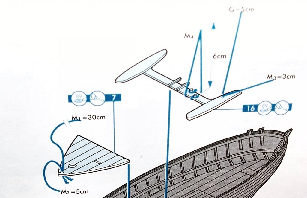
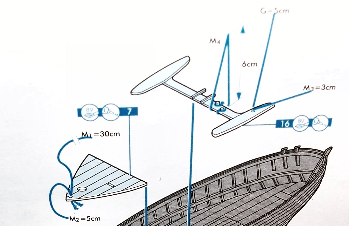
Today I had to make a decision about the rigging and painting the boat. The Heller instructions as shown below, have you add the rigging line to parts before you glue them in place, a not unreasonable approach, but not if you want to paint the boat as an assembly, to avoid glue damage. Also the foredeck takes a bit of force to get in place, and doing so would damage the nearby paint.
So I decided I’ll have to add the rigging in creative ways later.
Another problem is that the mast hole in the foredeck is cast off-center, making the mast lean to one side. The deck also didn’t fit quite right. I sanded one side to bring the hole more toward the center, and allow the deck to fit all the way forward. The best I could do still leaves the mast tilted, but much less so. I’ll trim the locking tab off the bottom of that mast, allowing me to shift it to correct this problem. The slight offset of the mast will be less noticeable than trying to enlarge or redrill the hole.
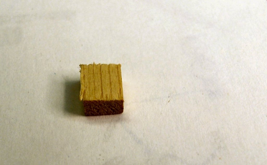
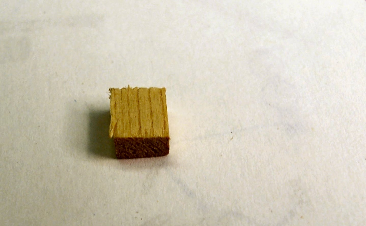
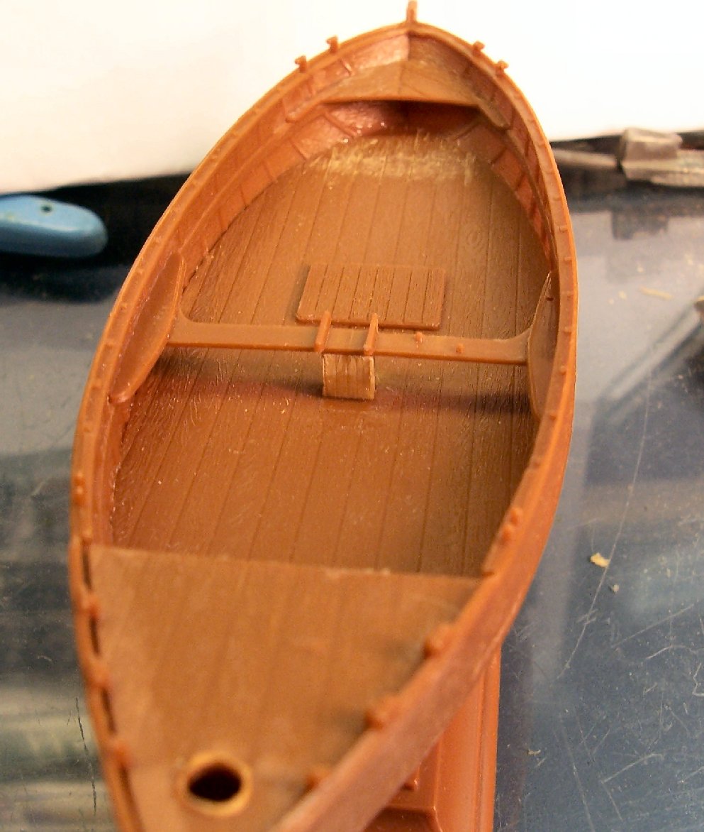
The part that I mentioned disappeared yesterday, turns out to be a support for the thwart (part 16) shown above, as well as a strengthening post for the mast base. I cut a replacement out of wood.
The next task was to carve away an ejector pin mark that prevented the thwart from sliding far enough forward to sit properly, not a difficult task. The other ejector marks were below the plank surfaces, so didn’t interfere. I’m not going to try to carve these away, for a better bulwark appearance, I’d just do more damage than good.

Here is a shot of the support, foredeck, the thwart, and stern seat installed. The wood support was attached with superglue, due to the dissimilar materials. I now shy away from this type of glue, due to the tendency to shear under a shock load, but no chance of that here.

I also cleaned the flash off of the bowsprit, masts and one of the gaffs.
The next installment will be a few days away. I’m busy the next few, and then I have to dig out my airbrush equipment. Though the latter might not be needed if I decide to try the Humbrol paints.
-
-
Well Non violent, except to the fish! :-)
- michael mott, lmagna and cog
-
3
-
-
PART 1
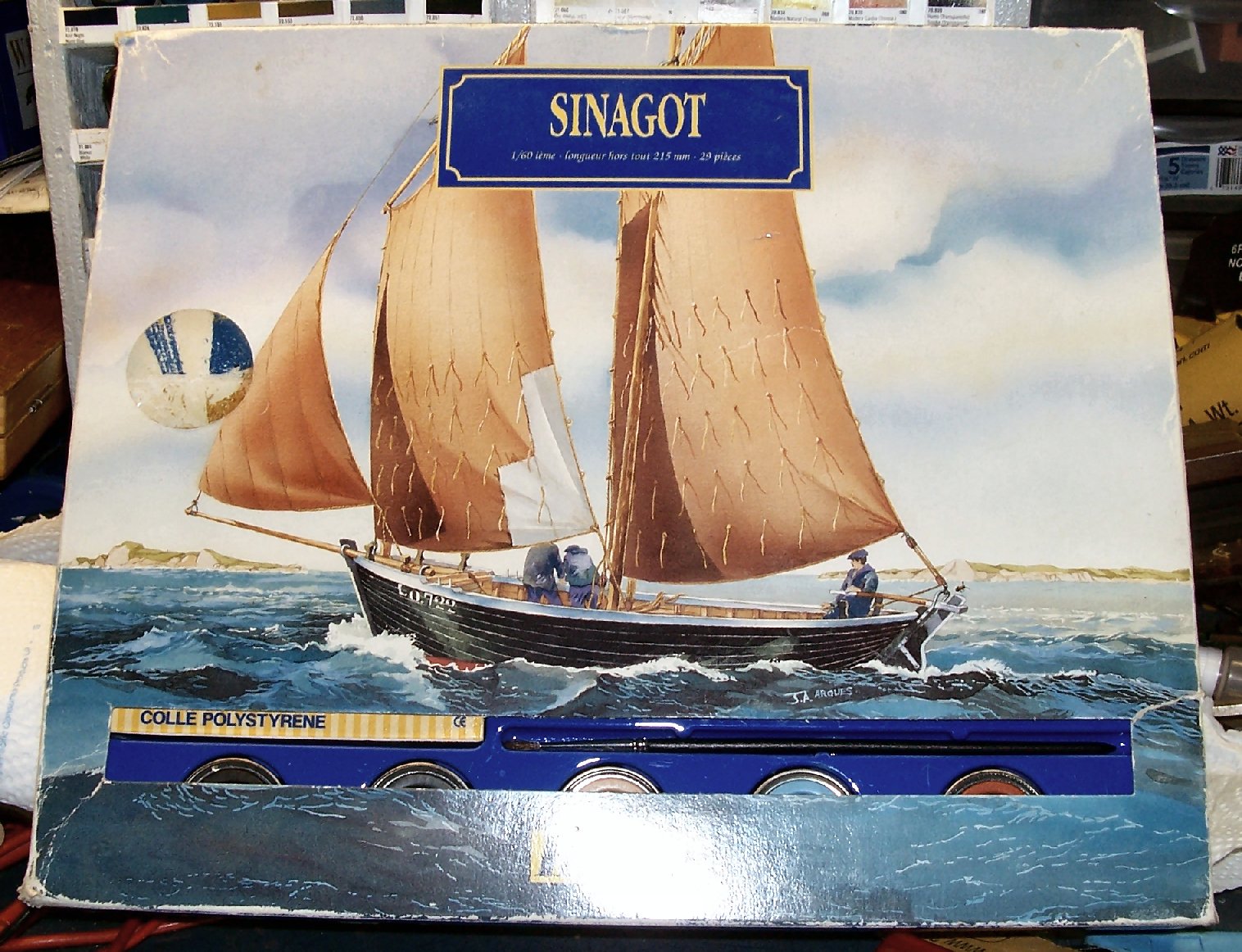
It has been a long time since I worked on any of my boats, and it will be a while before I can continue on them, but I needed to do something, so I picked out my Heller Siganot kit for a quick build.
This is a model of a ~42’ French two masted gaff rigged fishing schooner in 1/60th scale. Sorry, I forgot to take a picture of the kit contents.
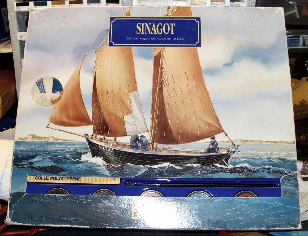
It includes the paint, but I don’t know how old the kit is, quite by the box wear, so I may use my Vallejo Paints. I may have to make new decals, also, the ones provided in the kit are black, and will not stand out well on a black hull. The box art also shows a slightly different pain scheme, with the white trim, not a color provided in the kit.
First was gluing the hull halves. The fit was quite good. I’m using Faller glue.

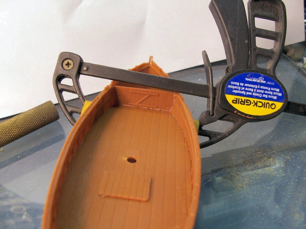
Next I built the boat’s tender.

As a general note, yes I’m getting a bit too much glue on the joints. My hands shake a bit, and sometimes this affects my glue application. I need to get some liquid glue, in addition to the thicker Faller type.
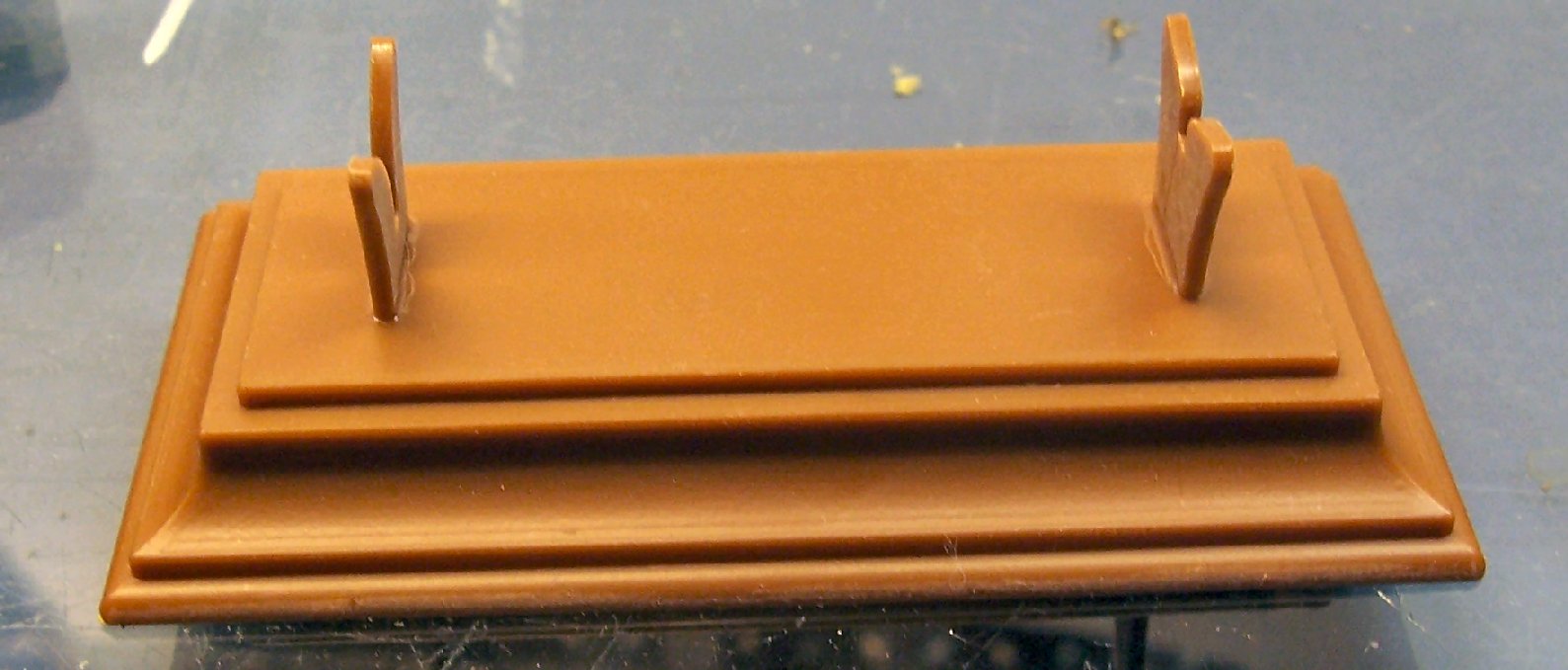
Next I assembled the stand. The pedestals had ejector marks on one side, so I put a piece of 400 grit sandpaper flat on the bench, and sanded that side in a circular and back and forth motion. A figure 8 motion is better, but these parts are small and difficult to hold.

There is a supplied name plate, but I’m going to wait until the boat is mostly done to attach it, as the keel sits at an angle, so the pedestal openings are not the same height, and I’m not to the point of setting the hull on the stand, to see which “direction” makes the hull level, nor which side of the boat turns out looking better.
Now I found a problem. Heller’s instructions, have you set the tender inside the stern, for display. This would prevent sailing the boat, in real life, and is also not really true to life. If the boat was moored the tender would be used to get to shore. If docked, they might pull in in, I’m not sure.
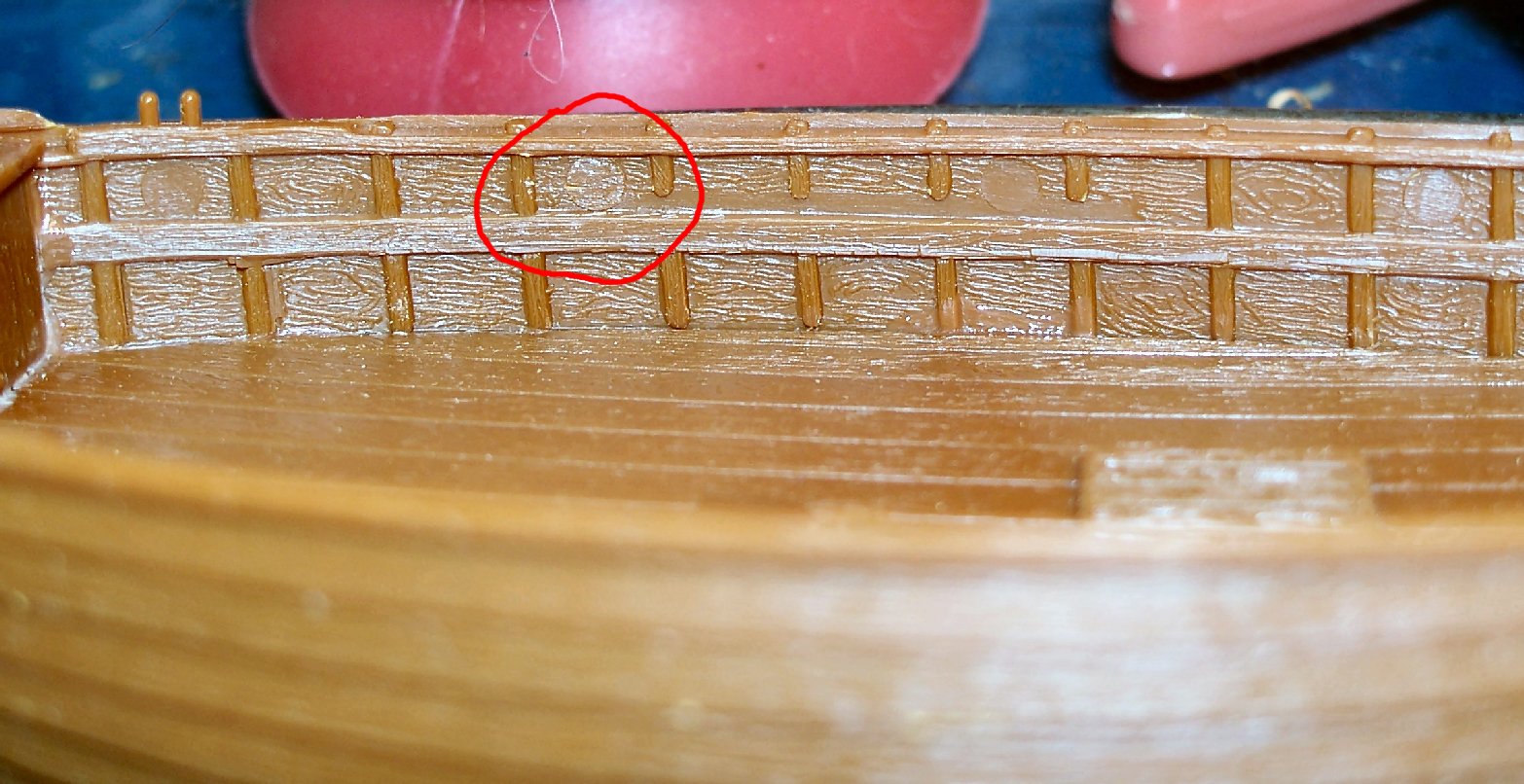
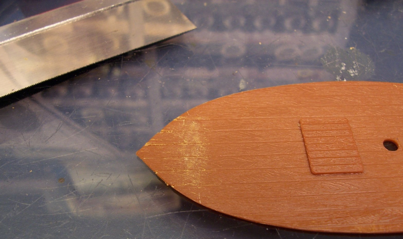
In any case, if sailing the tender would be at best towed behind, or perhaps left at the mooring. I'm still debating displaying the sails as set or stowed. Not a real problem, except, they have a untextured mounting boss on the deck, for positioning the boat for display! It would not look good, if I decide to build her with the sails set.
Above is a picture of the boss, with it partially whittled away. Using a curved #22 blade, I carefully carved it off, even with the deck surface. I used a large razor saw blade to cut in the planning grooves. I then dragged the saw lengthwise over the area and the surrounding deck to blend it in with the molded in texture.

After some cleanup, it blends in well. The hatch has already been attached.
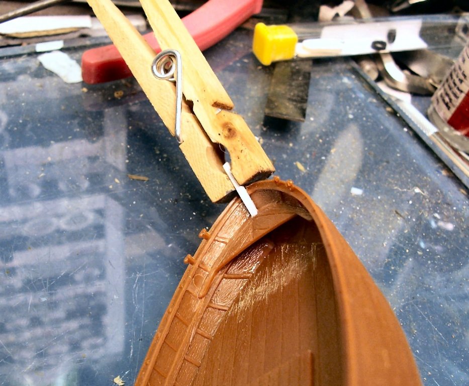
Today when I went in, I had a small shock. There is a small hollow cube that attaches to the deck, near the foremast. I think it is the air pipe for the live well. Last night I glued the two halves together and left them clamped in a clothespin, to setup. This morning the clothespin was sitting where I left it on the bench, but there was no part in it! It has apparently gone to that great part heaven in the sky! I looked, but my shop is a horrible mess, from moving stuff, while I renovate it, and it has fallen in some crack, and disappeared! At least it will not be hard to make another one.
The last part today was installing the deck and a forward bulkhead. Hopefully that won’t disappear too!
-
Came late to this build, but like what you are doing on it. I have several of these kits, and will continue to follow yours. Good job!
- EJ_L, popeye the sailor, lmagna and 5 others
-
8
-
-
Wye River Models sells one, but I don't know what the kit consists of. I have a Horizon Models one, but you have to do major carving on it to get it even close to the proper hull thickness. Wye River seems to sell a lot of their kits that strongly resemble the old Horizon ones, so their's maybe the same.
-
What does the engine look like?
-
Nice book, downloaded it. It will be interesting to look at, can't read Dutch, but the drawings are great!
- mtaylor, Canute, flying_dutchman2 and 2 others
-
5
-
-
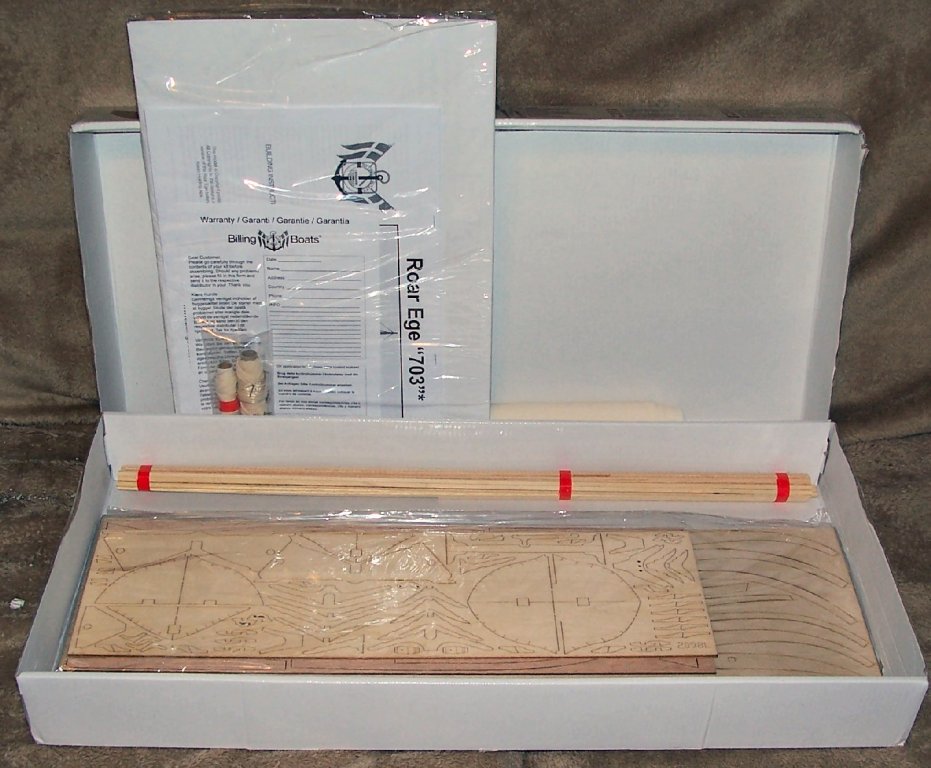
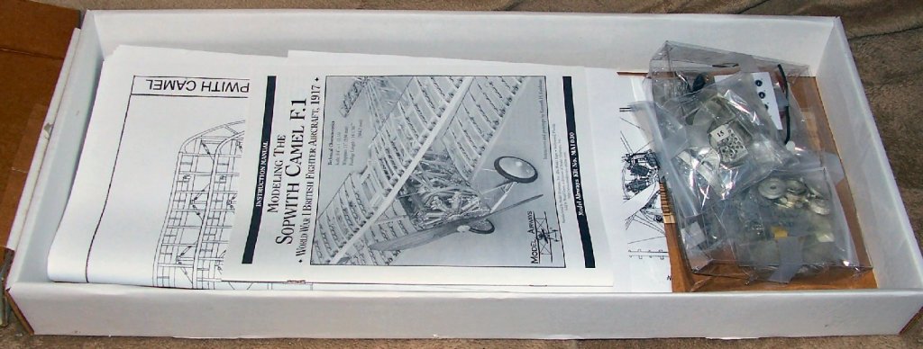
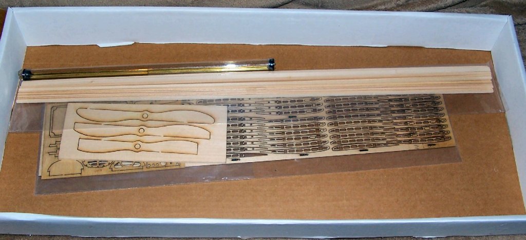
I'm offering three kits for sale to the forum members, before I put them on Ebay tomorrow night (Sun 6/10)
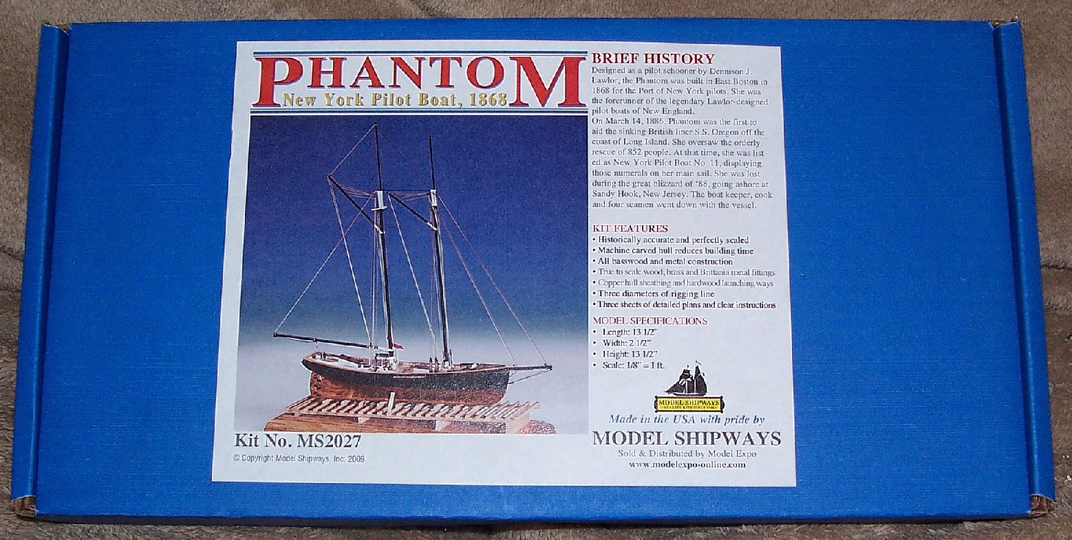
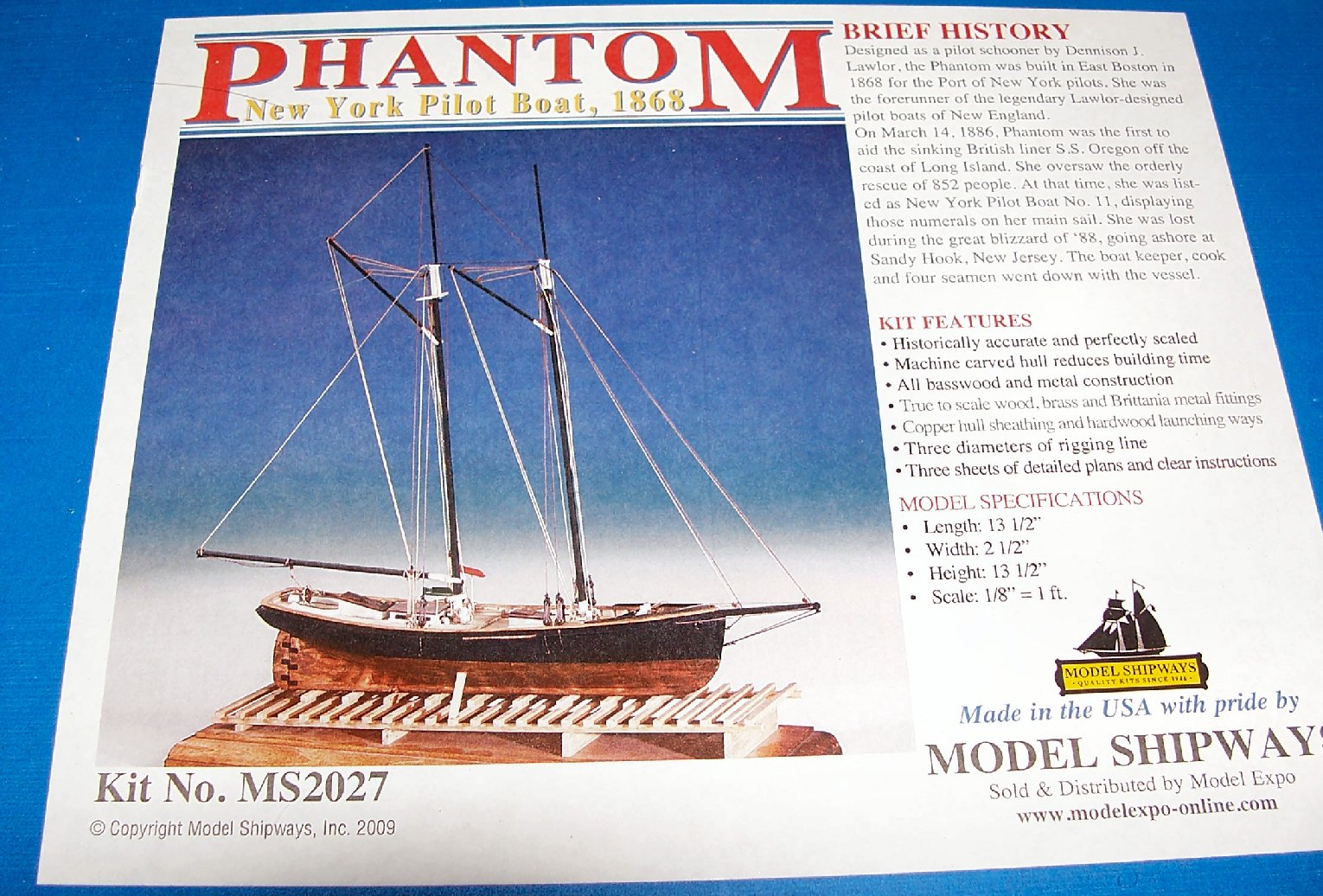
The first is a Model Expo solid hull Phantom 1800s (1/96) (the newer kit) still sealed. I'm asking $30 plus actual shipping. The shipping box weights 2 1/2 pounds and is 17"X10"X4"


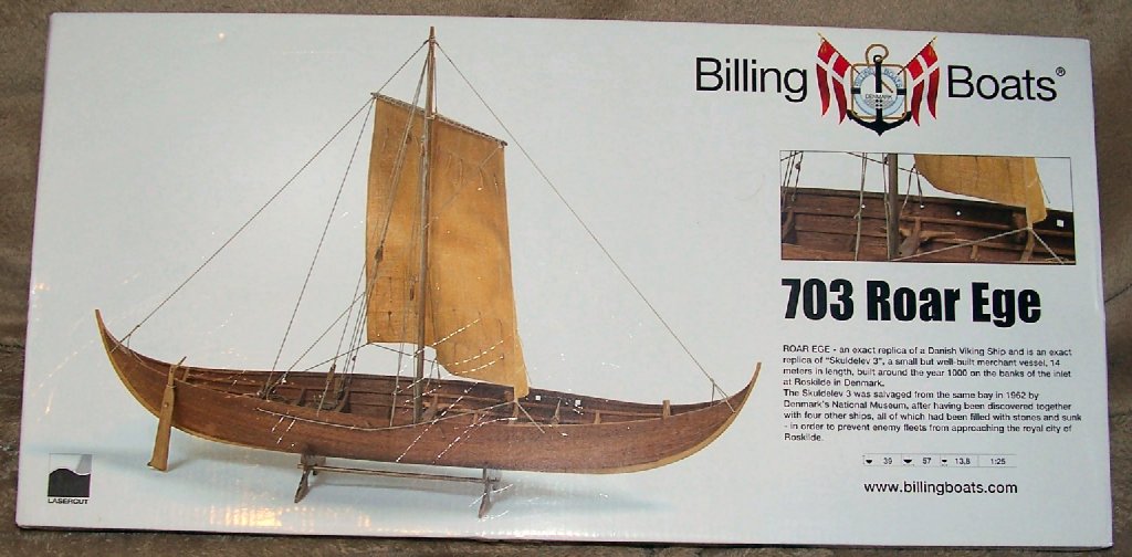
The second is the Billings Boats Viking ship Roar Ege about 900AD (1/25) opened for inspection. I'm asking $50 plus shipping. The shipping box weights 4 pounds and is 27"X12"X4"
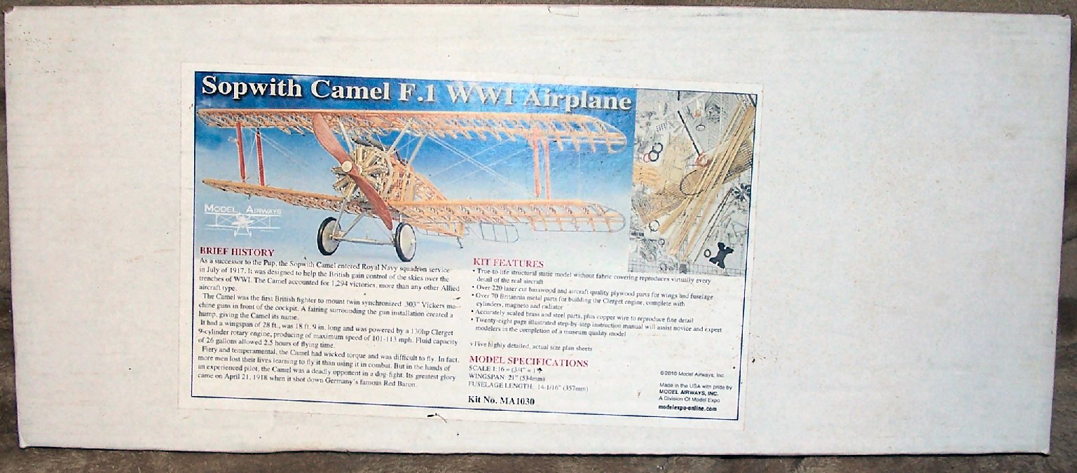
The third is the Model Expo/Model Airways (1/16) Sopwith Camel kit purchased new and only opened for inspection. I'm asking $100 plus shipping. The box weights 5 pounds and is 27"X12"X4". Note that most of the fuselage on this plane is wood, hence most of the laser cut parts are the wing ribs.


Sinagot by thibaultron - Heller - 1/60th - PLASTIC - Small - French fishing boat
in - Kit build logs for subjects built from 1901 - Present Day
Posted
PART 4
Yesterday I took a closer look at the box art for the loop over the tiller.
It turns out that the loop is a type of main sail traveler. It also mounts on the aft of the stern timber, not the inside , like I thought from the instructions. I should have looked at the art first. Of course, the artwork also shows knights heads fore and aft, not the cast in cleats on the model, but I’m not going to make that change.
On the back of the box a closeup drawing of the stern is also given, but without the traveler in place. This drawing, seems to show that there should be a, at least, a little of the stern timber inside the boat, so I shaved the piece down that I’d added earlier. It also, unfortunately, shows random lines going nowhere, including to the top of the tiller!
Here is a shot to show the relative size of the model, compared to my hand.
I installed the traveler, and finished blending in the foredeck/gunwale area.
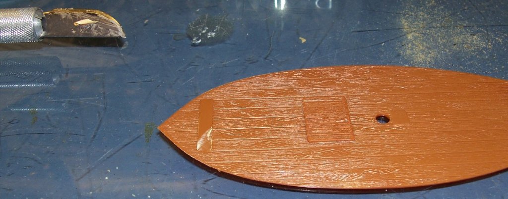
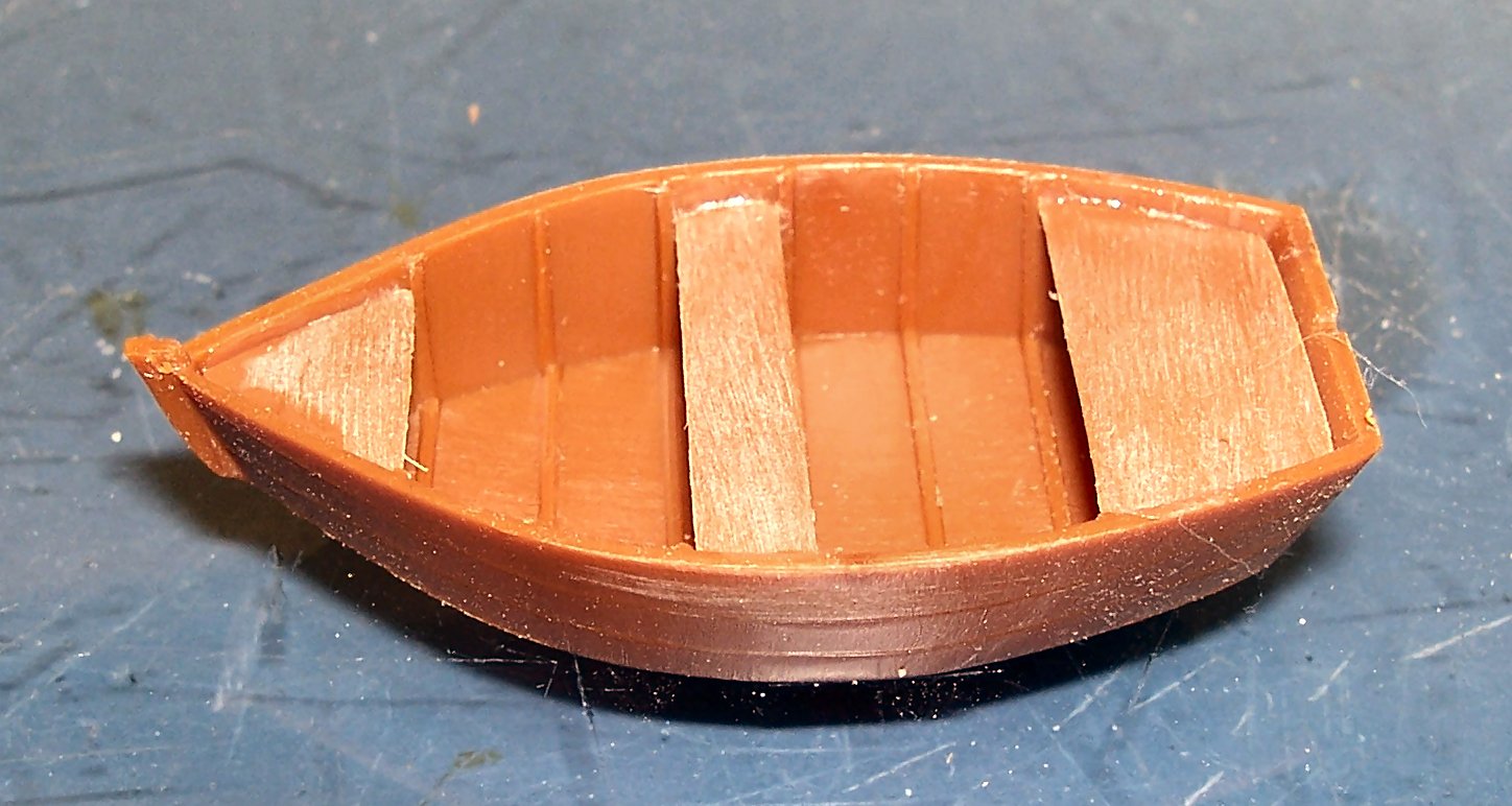
I’ve decided to not mount the tender in the boat, so I need to detail the tender’s bottom. I started out by sanding in some woodgrain. The grain on the interior runs fore and aft, so that’s the direction I ran it on the bottom. There is no indication on the inside of the tender to indicate any planking joints for the bottom , so I’m going to model it as one full width plank on each side of the keel.
My next step is to add a keel, but unfortunately, I can’t find my pack of styrene sheets, so that will have to wait until I get paid next week. I’m sure I have that pack somewhere, but it’s gotten buried in the moving of stuff during the shop renovation.
I’m thinking of mounting the supplied base to a board, and suspending the tender on a clear rod attached to that base, as if it is being towed behind.