thibaultron
-
Posts
2,952 -
Joined
-
Last visited
Content Type
Profiles
Forums
Gallery
Events
Everything posted by thibaultron
-

Painting a ships hull
thibaultron replied to bluenose2's topic in Painting, finishing and weathering products and techniques
There were two types of early "anti-fouling" type coatings used below the water line: White Stuff and Black Stuff. The White Stuff was used in colder waters, the Black Stuff in tropical climes. The Black Stuff was a dark brown to black color the White Stuff was an off white. Vallejo Ivory 70918 in the Model Color line is suposted to be a good match for White Stuff. -
Generally all ship's boats were lowered and towed behind during battle, so them hanging in front of the guns would not affect battlewothyness. Servicing the guns and port for normal cleaning may have been a pain though.
- 258 replies
-
- 2
-

-
- harriet lane
- model shipways
- (and 1 more)
-
One thing to note. Most of the modern Diorama/Figure painting books assume you start with a model with heavy woodgrain patterns cast into the surface, not a smooth plastic one. Buy some of those cheap plastic "For Sale" signs at the hardware store and practice on the white backside, of the sign. Pratcicing on cardboard or paper will give different results, as they absorb the paint differently. These are great for practicing airbrushing also, as well as testing your paint color/mixes for final dried look. I tried several techniques using a Revell DR-1 1/32nd model. While the model is a newer one, they cast it with distinct wing ribs rather than the gentle sagging fabric skin between the ribs. The distinct ribs allowed me to segragate the various tries, and then record the results, for future use.
-
Beautiful model!
-
CAD is an alternative to the Mylar. You still suffer from paper changes, but you can reprint the sections of the plan as you get to them, so long term changes can be compensated for.
-
The Shapeways printers are much higher resolution than the ones you can buy, reasonably. Theirs run in $10,000s of dollars. As in many things in life, money brings quality. In my experience, depending on your scale, larger pieces can be printed in 1/96th scale smaller in 1/64th or greater. In HO (1/87.1), They have successfully printed 1 1/2" rivet detail for me. In 1/64th some larger cleats. and cheek blocks.
-
You might want to consider an ink jet over a laser, many of them have higher resolution.
-
I'm following along with interest! In about 1960, when I was a "Wee Lad", my grandfather built a 16 foot runabout, over the course of a couple years, at his camp on the ST. Lawrence River. I have many years of fond memories of both the Grandparents, that camp and the boat, all gone now. I wish I knew what plans he used (I think it was a kit boat), even some pictures of it. Both my brother and I (as adults) tried to get him to sell us that boat when he sold the camp, but he wouldn't. We never figured out why.
-
My great-aunt's Travel Diary c.1903
thibaultron replied to Mike Shea's topic in Nautical/Naval History
At least they can read cursive!, here in the US they are seriously talking about not teaching cursive! Claim no one uses it any more. -
On a model getting that slight catenary on the shrouds to look right would be difficult. They are like the rest of the rigging, in real life all the rigging sagged some, even under load. On a model, assuming the thread did not curl, or misshape itself when not under load, getting that sag would be very difficult. You also have to consider the audience Others looking at your sagging rigging will just think you did a poor job.
-
Great effort for a good cause!
-
I looked at the kit offerings, and the Battue(sp) is on my short list for purchase!
-
Nice!
-
Many years ago I went to a museum, where they had a very detailed model of a riverboat that had been (model) built in the 30s. Unfortunately it had been painted with what looked like house paint! The finish was thick, lumpy, looked terrible!
-
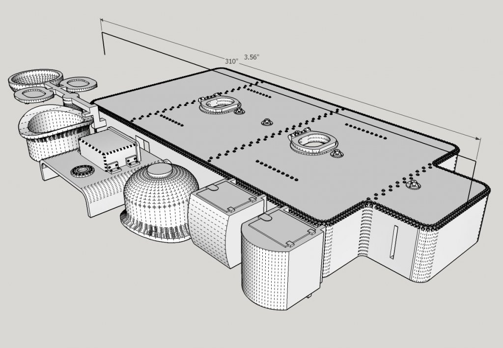
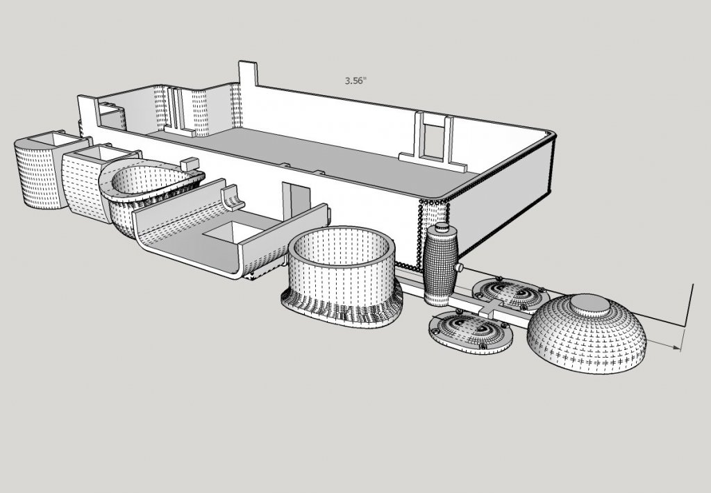
Latest 3D printing project: An oil bunker for an Bachmann Spectrum 2-8-0 HO locomotive, two tool boxes for the tender, and a new dome for the boiler. This model has two domes, the 2 part on is for initial fitting, and the complete dome for the final install. Over a thousand (1 1/2" diameter scale) rivets, and yes the total length of the parts as shown is 3.56". The slots in the side of the bunker are to fit over the existing "walls" of the coal bunker (after the bottoms are cut out of the slots). This leaves the ability to change it back to coal, much as the Santa Fe railroad did in real life. The oil bunker was a tank that sat in the coal bunker, instead of the coal load. I've spent waay too long designing this, but it was an interesting exercise. This is version 2.0, the first part was just for a trial fit, and ended up needing a few dimension changes, as expected. The first printed part had damage to the rivets were the Shapeways tech pried it out of the printer. In the end the 3D printed part is probably too fragile for production selling. If I decide to sell this, I'll probably have to use the final part as a master for resin casting. Why the 2 part hatches (base and cover)? I plan to sand the cover to a scale thickness, hence the recesses in the bottom of the covers.
-
CA adhesive- spontaneous combustion?
thibaultron replied to Srodbro's topic in Metal Work, Soldering and Metal Fittings
Setting CA generates heat, as part of the chemical reaction. -
I know there are a lot of curve extensions, but I haven't found one that actually creates a smooth curve that follows a set of points. Lots of Besler curves, but not a spline type. Do you know of a spline type extension?
-
Fokker Dr.I by Torbogdan - FINISHED - Model Airways
thibaultron replied to Torbogdan's topic in Non-ship/categorised builds
Looks great! -
To get a more opaque white star. perhaps a light coat of white paint, overall? don't know how that might interact with the printer, or ink, though.
- 749 replies
-
- 1
-
-
- albertic
- ocean liner
- (and 2 more)
-
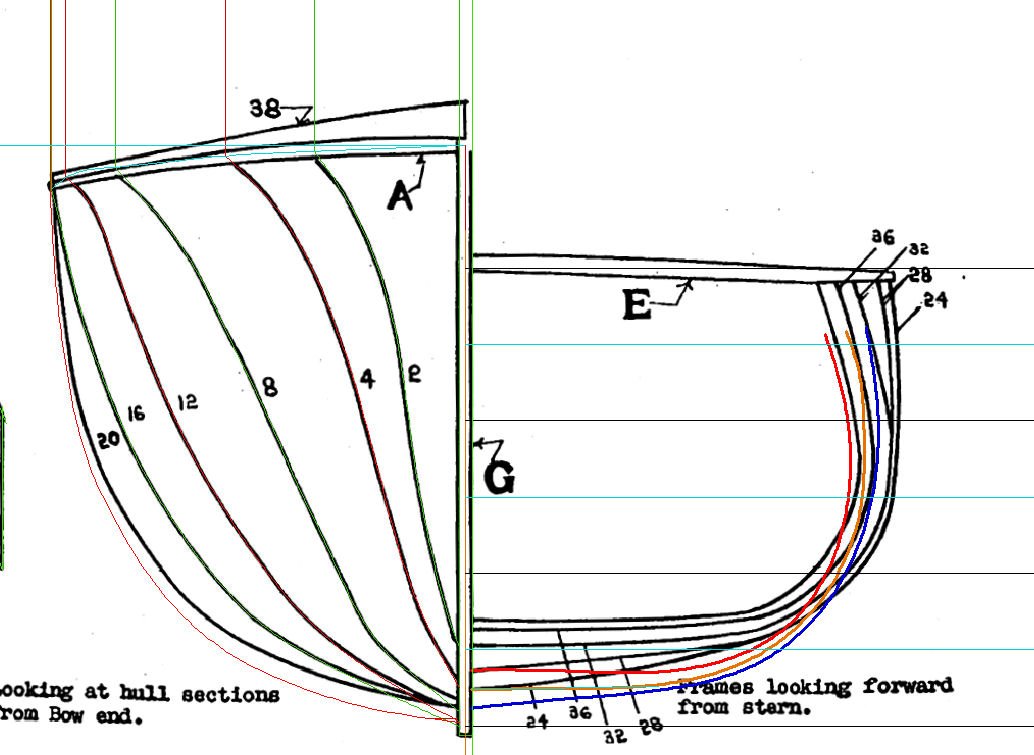
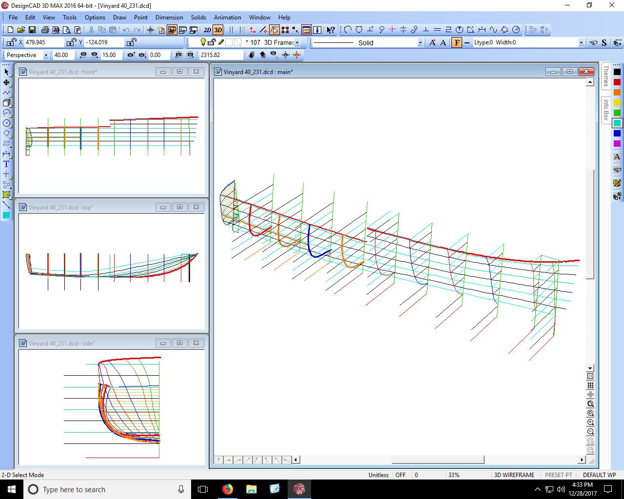
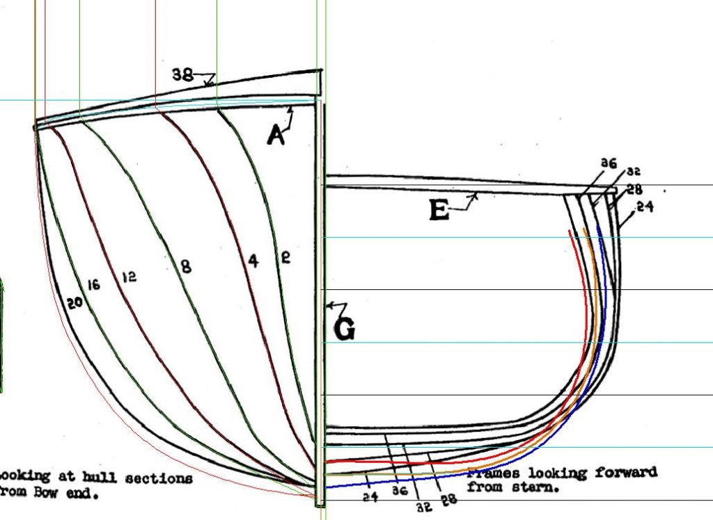
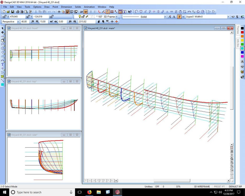
I use DesignCAD 2016 for general drawing and non 3D printing, and SketchUp for the 3D printing. You really need a good regular CAD program for going from drawings to ship frames etc. I use the 3D features of DesignCAD to check that the frames are "fair", and to double check other features. For example: Here is my redrawing of an old out of production kit. The frames as shown in the original drawing are very incorrect for the aft frames! I don't even know how anyone built the original kit, unless the supplied frames differed greatly from those shown in the drawing. Here are the before and after frames: The colored lines are what I got after using the 3D features to layout and draw waterlines. Here is the 3D layout with waterlines drawn: One thing that most of the CAD programs have, that SketchUp lacks is the ability to draw a smoothed curved line to match fixed points. With SketchUp you can draw straight lines between points, but not a smoothed curve. That is how I got the final frames. With the frames laid out in 3D I drew the curve between the frames and looked for dips or bulges. I then moved the offending points in or out until everything looked smooth. I the case of this boat I generated the aft frames using the fore frames, the deck outline, and the transom as data points to start. Now that I have good water lines, I can also generate intermediate frames, if desired. If TurboCAD costs $150, check out DesignCAD, I think that it runs around $100. I've been using it, in various versions for the last 20 years or so. You definately what a 64 bit CAD.
-
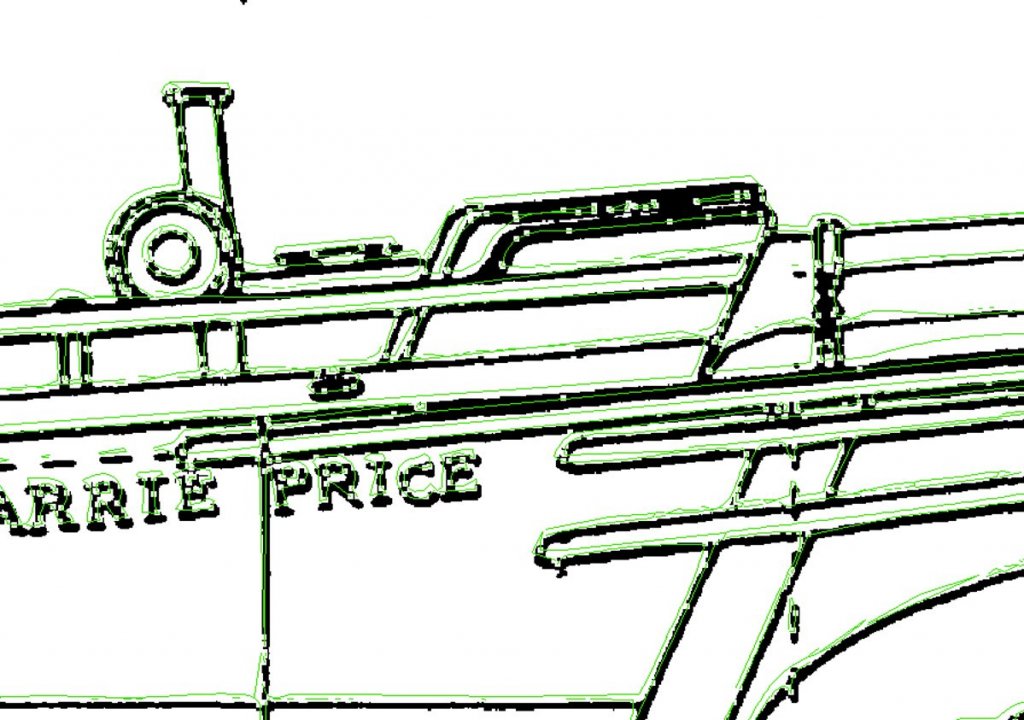
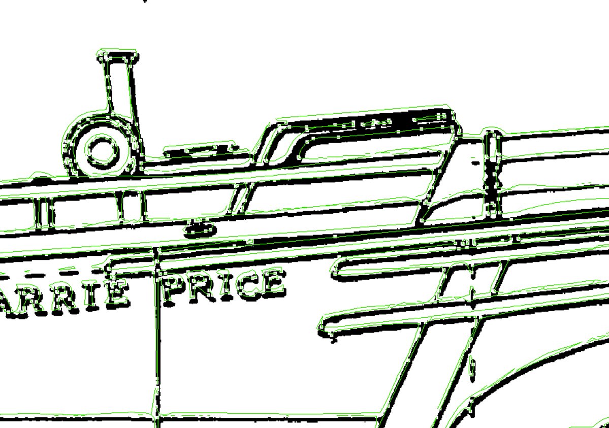
Forget the "Tracing" function! My DesignCAD "Trace" (by the same company), is not usable, for precision work. No company makes one that works well, enough. Here is an example of a trace of part of a scanned drawing. The trace is shown in green. Its better to bite the bullet, and manually trace the drawing.