Louie da fly
-
Posts
7,993 -
Joined
-
Last visited
Content Type
Profiles
Forums
Gallery
Events
Everything posted by Louie da fly
-

Lateen yards – inside or outside of the shrouds?
Louie da fly replied to catopower's topic in Masting, rigging and sails
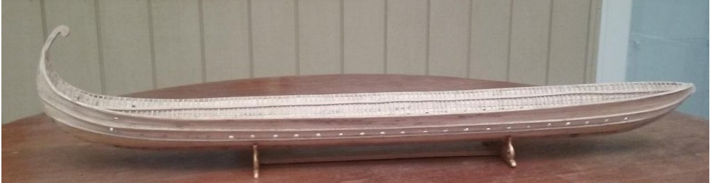
Precisely. One of the ropes on the vessel below is a halyard. But are the others shrouds or backstays? Or what? (rhetorical question - no answer needed). I must say, Wefalck's contributions have got me thinking about issues relating to lateens that I hadn't considered before. Steven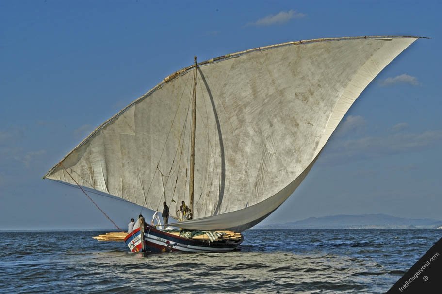
- 14 replies
-
- 2
-

-
- lateen rig
- washington galley
- (and 1 more)
-
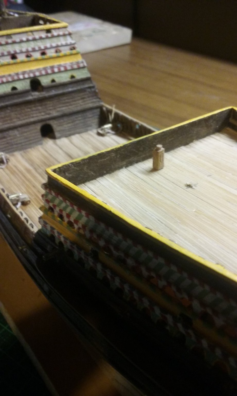
Like the water cooler in a modern office. Or in the Australian army in WWI they had water wagons made by J. Furphy and Sons. Though it's now dying out, the Australian word "furphy" is even today used for an unfounded rumour. Steven
-
Lateen yards – inside or outside of the shrouds?
Louie da fly replied to catopower's topic in Masting, rigging and sails
Wefalck, merci beaucoup pour la référence. Though I'll accept that a lateen on a small vessel can be used without shrouds, larger ships seem to need them. I don't know that there's really a difference between a lateen with or without shrouds. Steven- 14 replies
-
- 4
-
-
- lateen rig
- washington galley
- (and 1 more)
-
That's beautiful work, Derek.
-
Greetings from the shores of Lake Michigan!
Louie da fly replied to Jayhawk's topic in New member Introductions
Welcome to MSW, Jayhawk. When you get started on your model, you should also start a build log. The instructions are here: It's a great way to get help and advice as you go through your build. The people here are very friendly and helpful. Good to have you aboard. Steven -
Welcome, Derek! Do you have a build under way at the moment, or one planned? Steven
-
https://archaeologynewsnetwork.blogspot.com/2021/03/2700-year-old-phoenician-shipwreck-to.html?fbclid=IwAR0pj1HhLWQTGfJ3X8QnFmbG0teMmdZzVmnyt1p7wdUJChEW3ti7yIka9_8
-
Lateen yards – inside or outside of the shrouds?
Louie da fly replied to catopower's topic in Masting, rigging and sails
It depends. Historically they are shown doing so. But on small Mediterranean lateeners they usually don't bother. Note that there is a loop of rope that acts as a parrel which keeps the yard close to the mast. But it may be different with a bigger sail. I did quite a bit of research on this with my dromon build - see https://modelshipworld.com/topic/10344-10th-11th-century-byzantine-dromon-by-louie-da-fly-150-finished/page/41/ In Mediterranean lateeners the yard is and was usually outside the shrouds, but in galleons and other ships of the 16th to early 18th century, the lateen mizzen had the yard inside the shrouds; most probably because the mizzen wasn't the main source of propulsion. Steven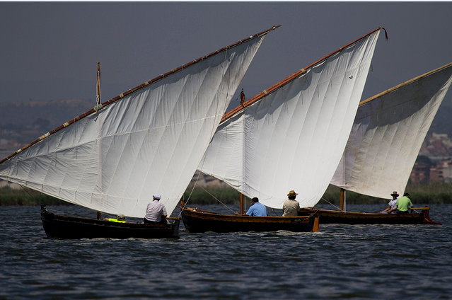
- 14 replies
-
- 3
-
-
- lateen rig
- washington galley
- (and 1 more)
-
He may well do - that is his right and privilege. But in common with many movies and TV series based on history, there are glaring inaccuracies in relation to such things as armour, equipment and costume, (though the swords look ok). Justin Pollard, the historical adviser on the series is a "popular historian, historical consultant and screenwriter" according to Wikipedia. But if he gave advice on such things I doubt it was followed. Unfortunately movies very rarely worry about such things - the director and costume department get a bigger say than the historical consultant. I've also spent years researching Viking history and artefacts, and though I may not be an academic, I do know when something is as wrong as this. Strangely enough, the shields are among the "least worst" of the gear on the show. Steven
-
That's looking very good, Balclutha. Keep up the good work! Steven
-
This is looking very good. You've made good progress and obviously mastered the clinker planking. Here are some more (genuine) Viking dragon heads (none of them from ships - none have ever been found) - but all from real Viking artefacts: Looking forward to the next progress. Steven
-
Unfortunately, nothing in the Vikings TV show bears any relationship to what Vikings ate/wore/did/carried/used. And most of the "Viking Shield Designs" that can be found on-line use a fair bit of imagination (i.e. they're made up) or extrapolate from Viking decorations in other contexts (i.e. they're made up). What is known about patterns on Viking shields appears here: http://members.ozemail.com.au/~chrisandpeter/shield/shield.html The ones you're making look good, but as there seems to be no evidence of standardization in shield decoration, you could mix and match patterns and colour combinations as much as you like within the colours available at the time - https://sciencenordic.com/denmark-history-society--culture/how-to-decorate-like-a-viking/1455997 . Steven
-
To be honest, Druxey, so am I. I keep thinking "Did I really do this when I was that young?" Maybe I don't give my younger self enough credit, but I seem to remember I was a bit of a twerp back then. Or is it that if I could do that when I was that young, why haven't I progressed any further in all this time? Interestingly, I did carve three figures for the ship out of bamboo back in the day, but they got lost sometime in the interim. It would be instructive to be able to compare them. But I do remember they didn't have the level of detail the current ones do. Steven
- 740 replies
-
- 7
-
-
- Tudor
- restoration
- (and 4 more)
-
Oh dear, oh dear. I won't say I haven't been tempted. But that way lies madness . . . Steven
- 740 replies
-
- 2
-
-
- Tudor
- restoration
- (and 4 more)
-
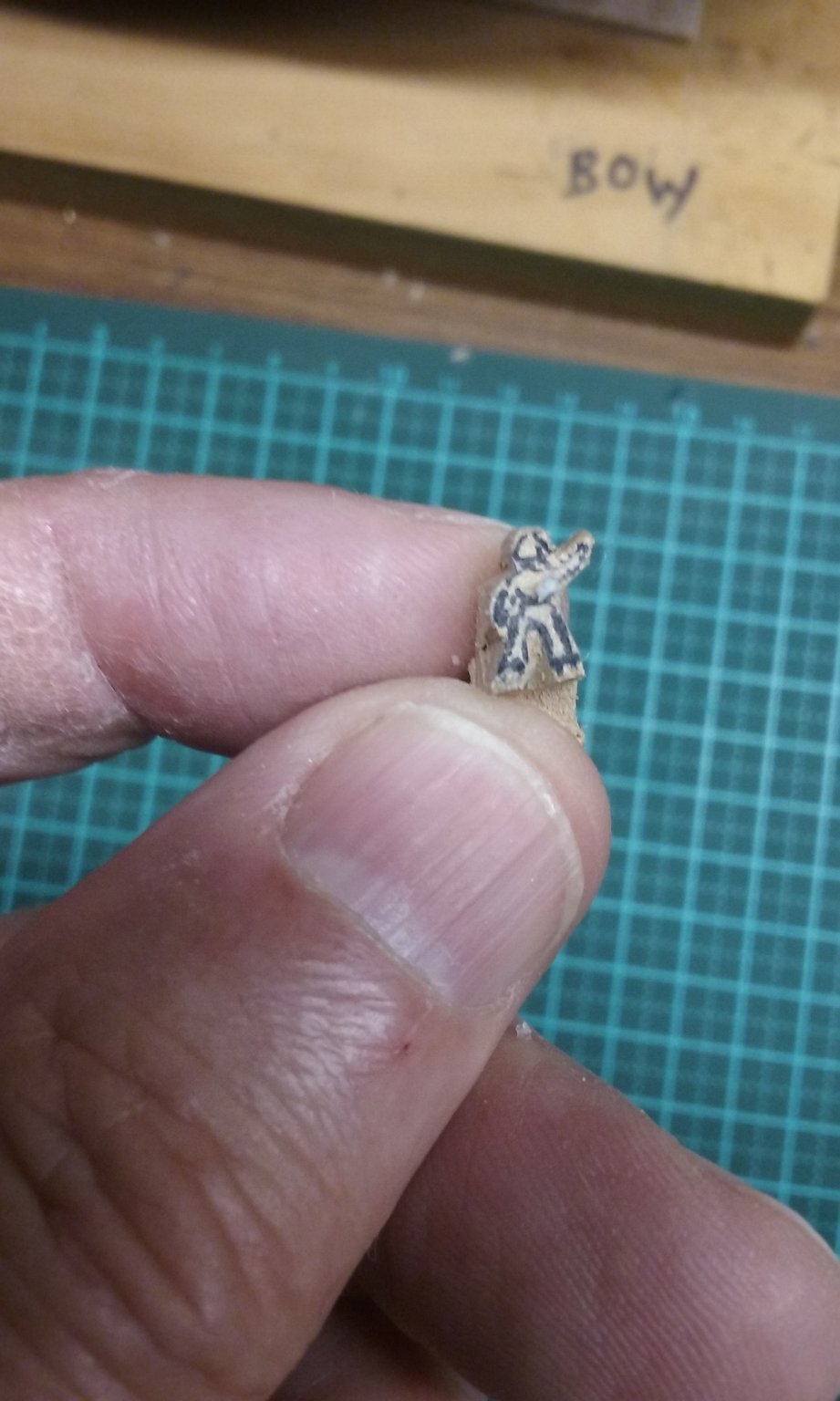
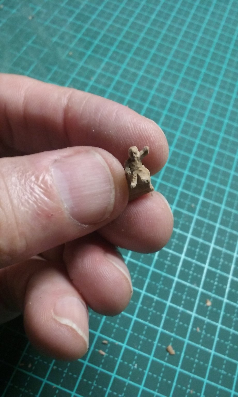
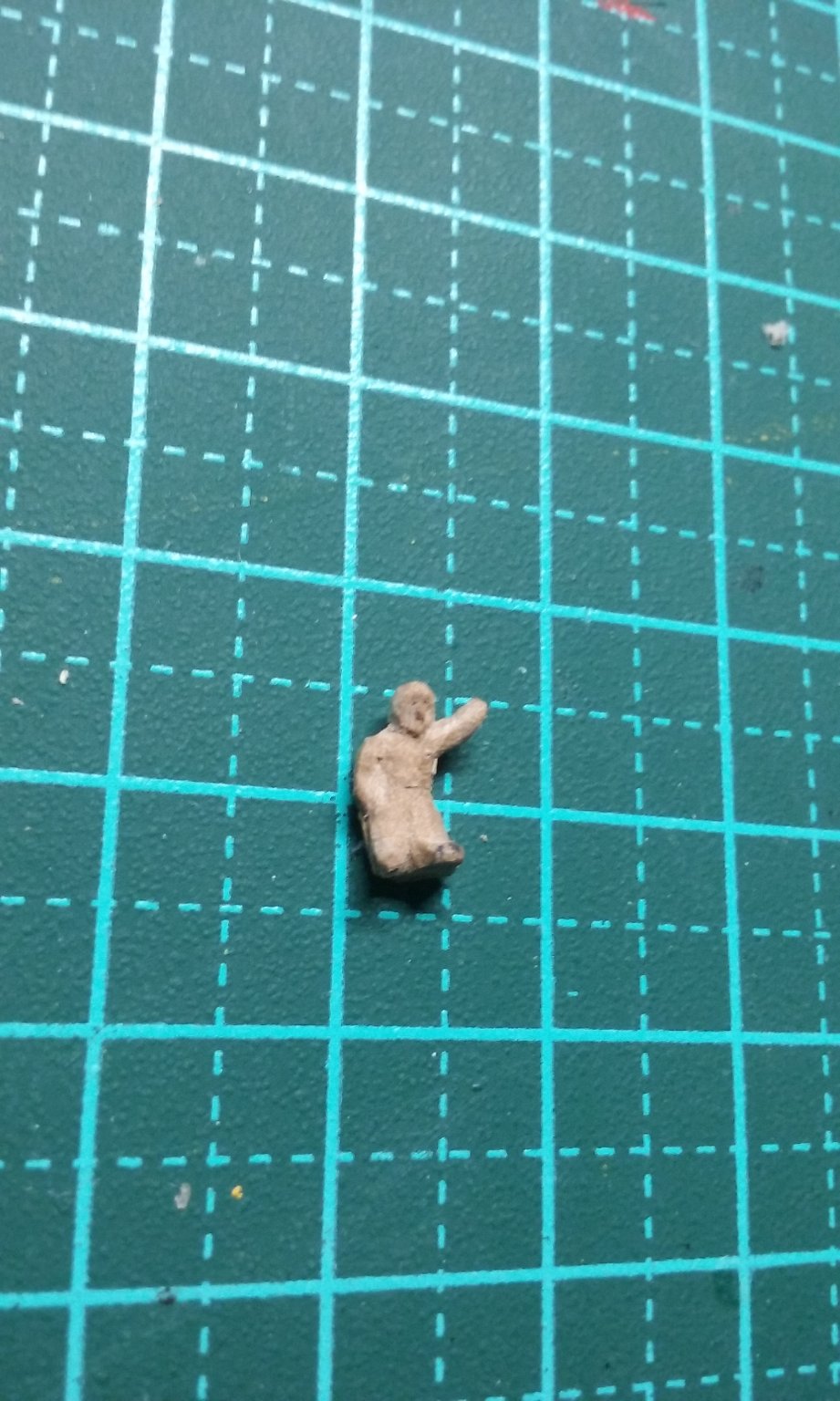
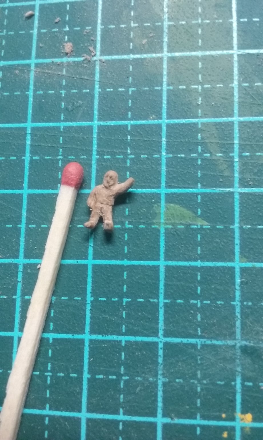
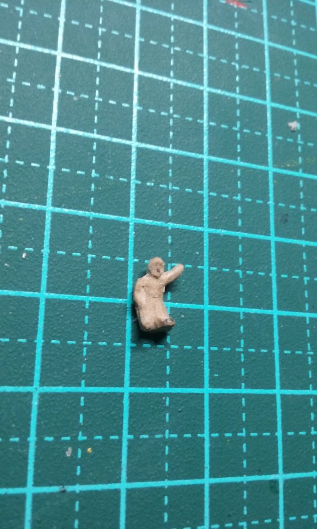
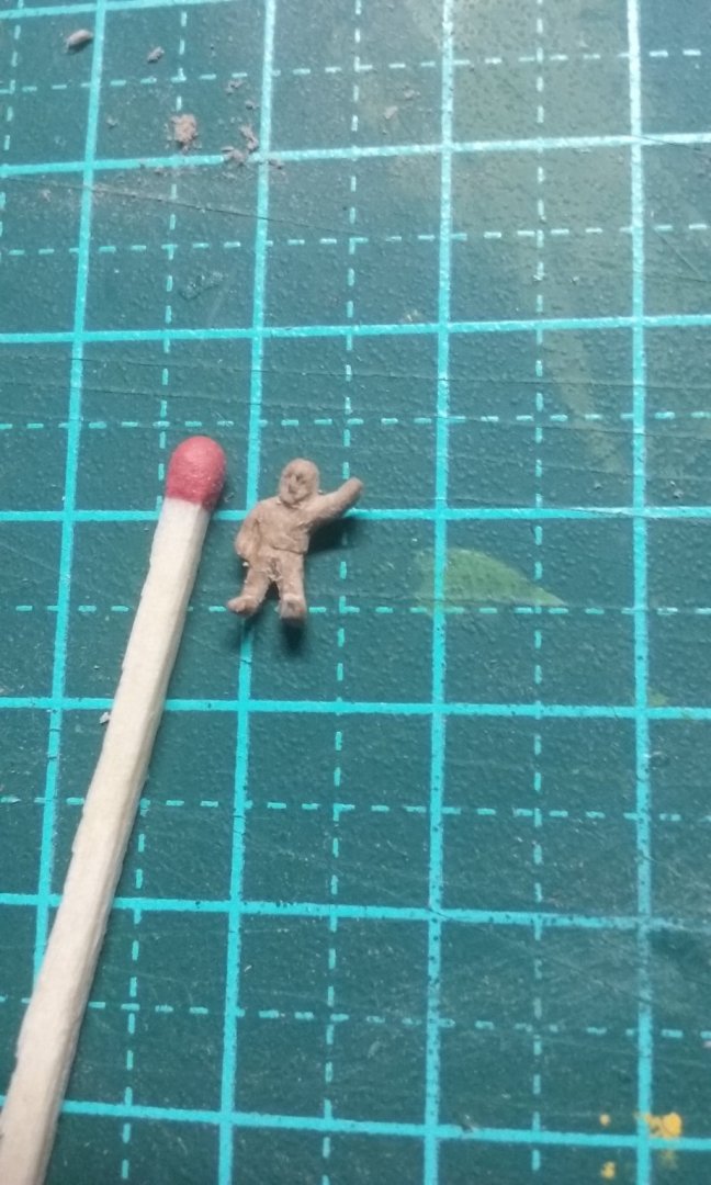
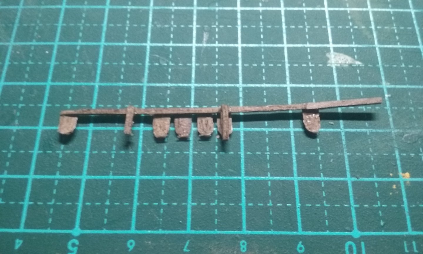
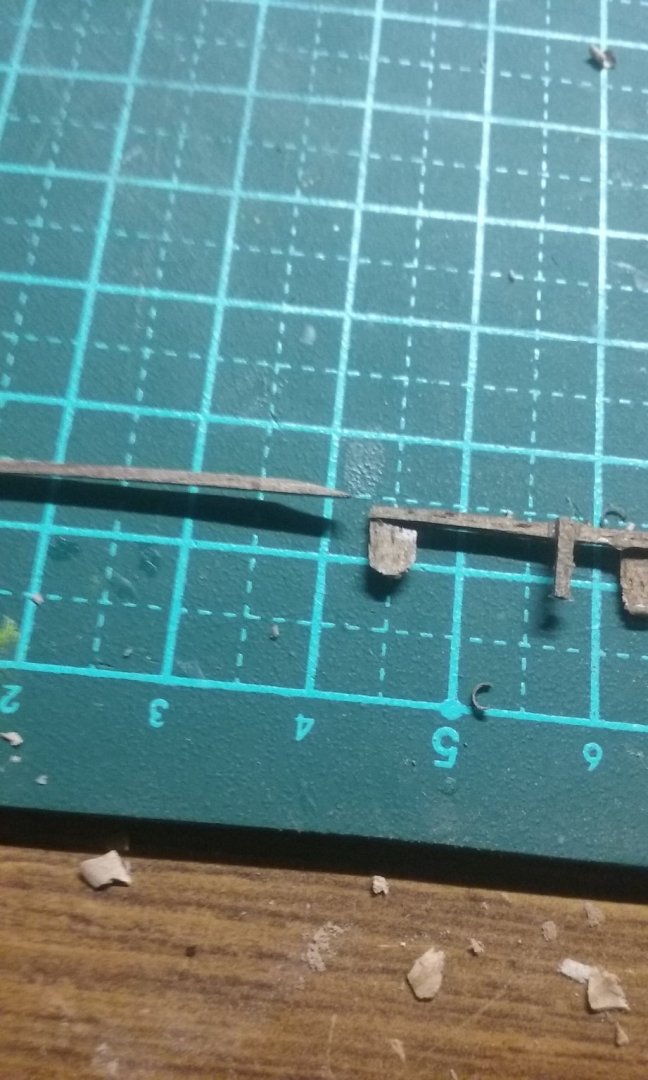
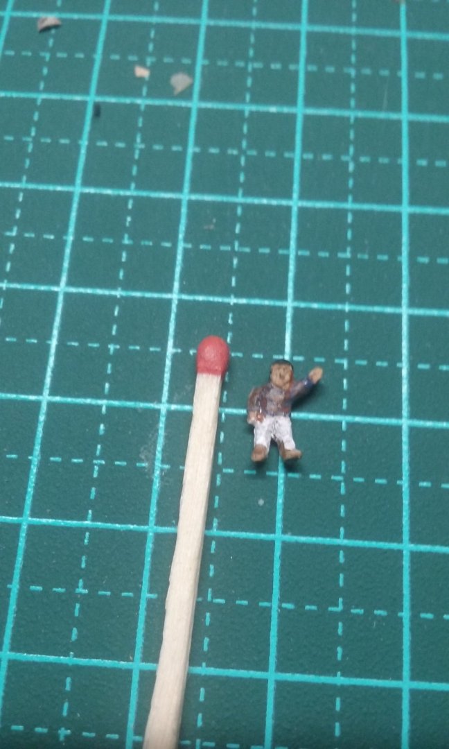
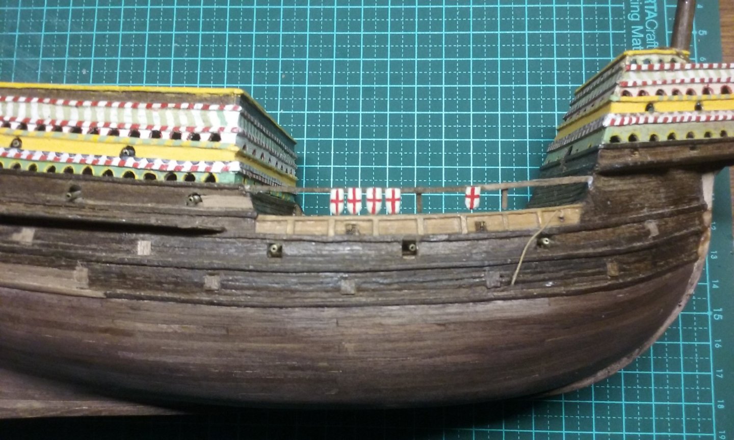
Making a third figure - this time a common sailor - probably to stand on a yard holding onto a rope. Or possibly it's John Travolta . . . And finally doing the railings for the main deck, one of which broke off short, and the other got lost. Here I'm adding extra length at both ends to the broken one, using scarph joints. And in place - just glued at both ends so far. Once that's dry I'll glue down the intermediate bits. Steven


- 740 replies
-
- 14
-
-
- Tudor
- restoration
- (and 4 more)
-
What a wonderful idea. I'm not sure if you already know about the Sutton Hoo Ship's Company, who are building a full-sized replica in the UK? https://www.facebook.com/saxonship Steven
- 179 replies
-
- 2
-
-
- longship
- Helga Holm
- (and 1 more)
-
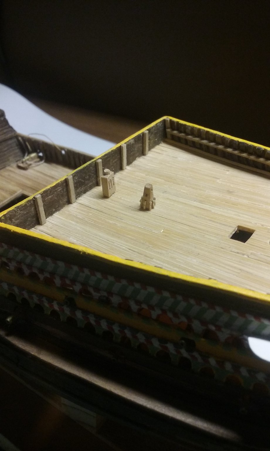
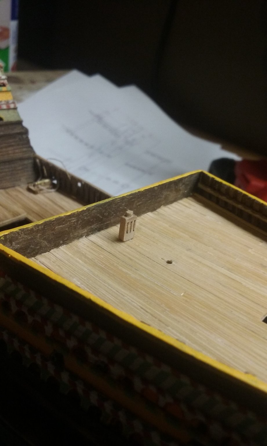
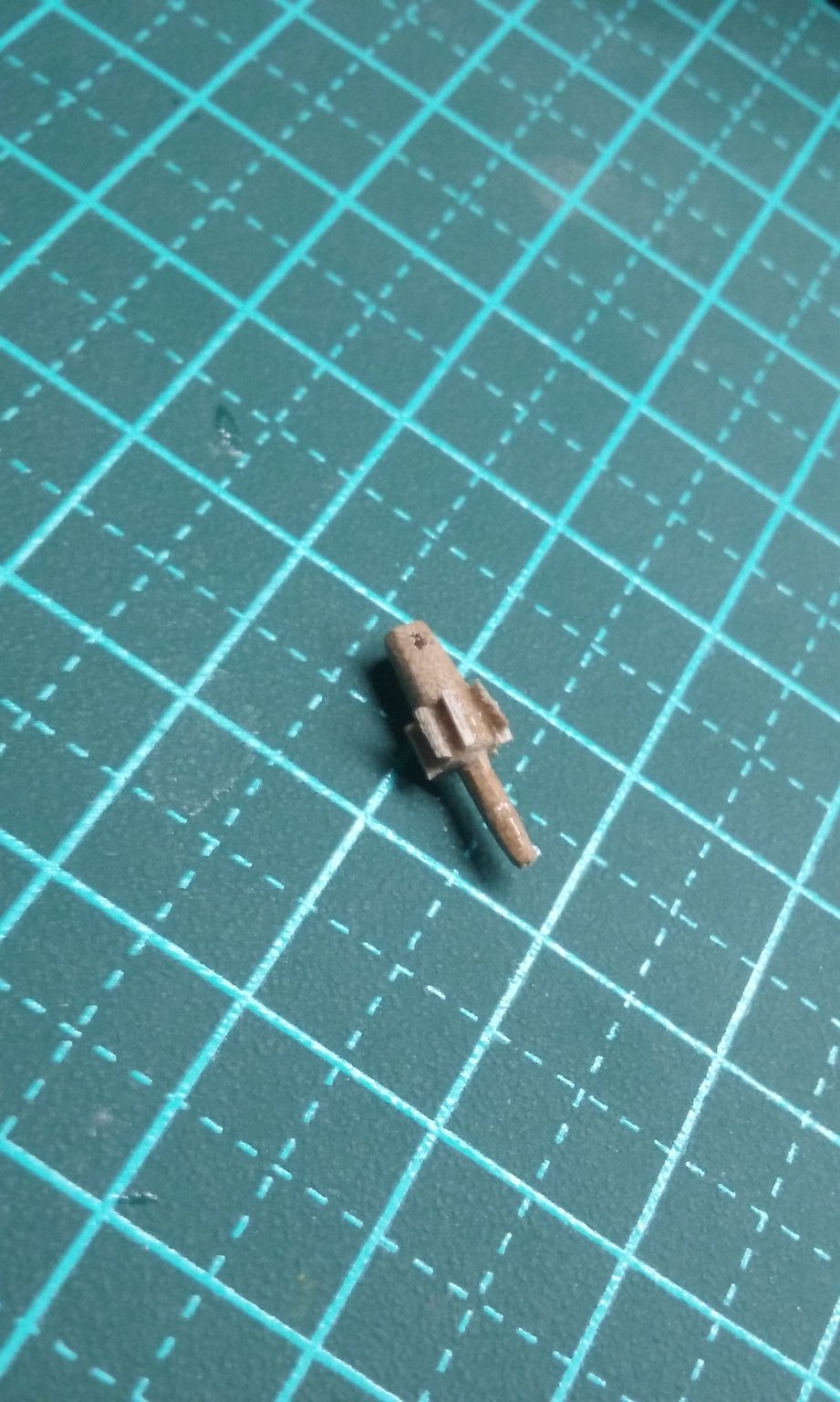
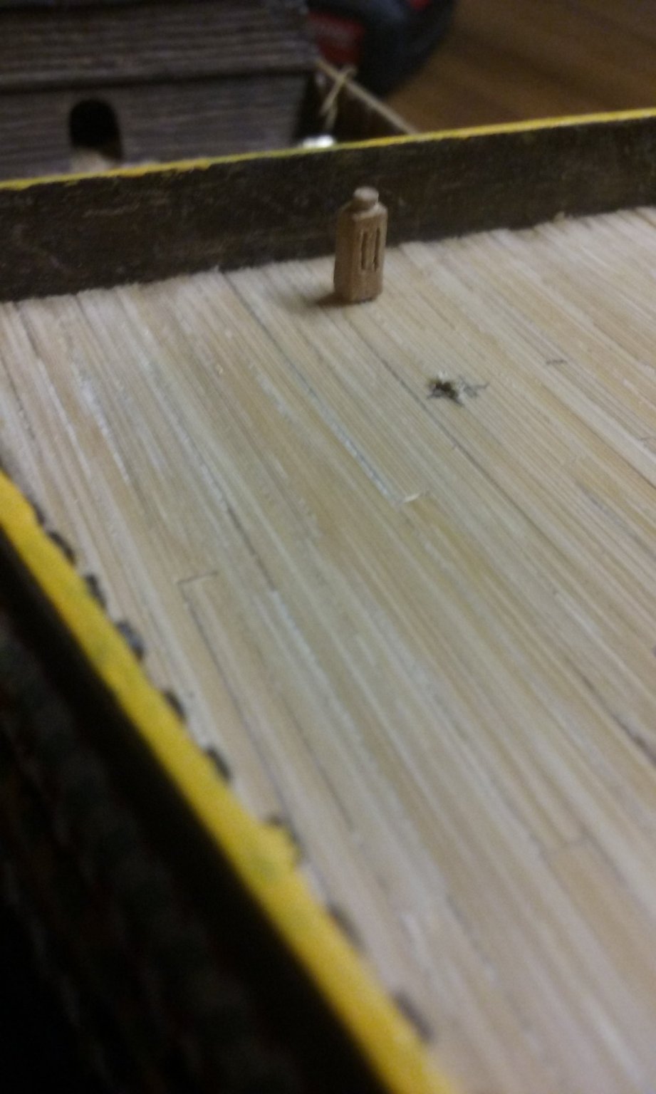
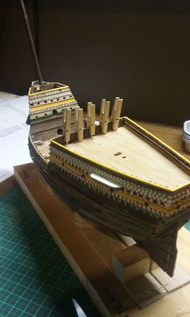
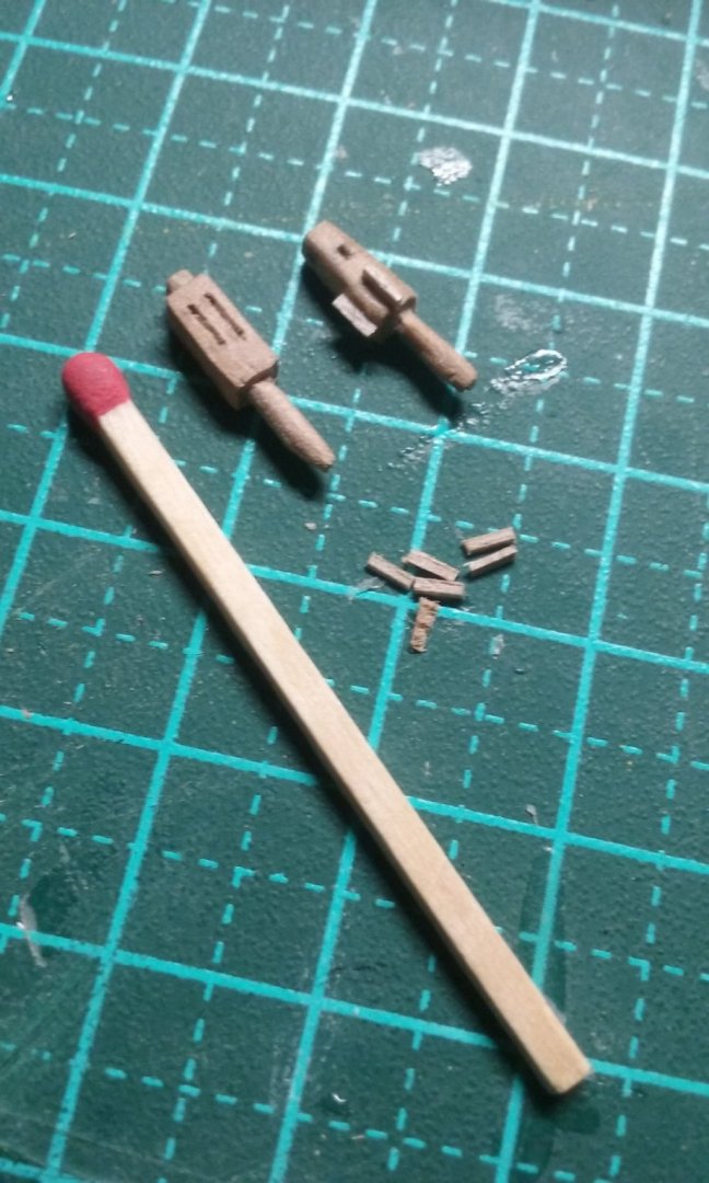
Added some uprights to support a crossbeam for belaying points. Capstan complete and dry fitted, along with the three-sheave knight (funny, why does that phrase make me think . . . Momma told me not to come?) Steven


- 740 replies
-
- 10
-
-
- Tudor
- restoration
- (and 4 more)
-
That'd be great. Probably your best bet would be to resurrect your build log and put them up there. And then you could ask any further questions on your build log as you progress through your build. Another point - when you hit problems specific to this model maybe you could PM the guys whose build logs are referenced above, and ask them directly. They'd probably be very willing to help (though of course I can't speak for them). And also Messis, who built this model in 2015. Best wishes with it. I look forward to seeing your further progress. Steven
-
Hmm, it seems to me that step 3 should be after step 4. The wales aren't especially thick planks, they're glued on over the top after the planking is done. If you look at the note at the bottom of the section drawing "Plank the hull completely with strips mm 1x3. Then apply wales which must be shaped from mm 1x5 strips", this tells you what planks are needed for what - the main planking is from strips 1 mm (millimetre) thick by 3 mm wide and the wales are from strips 1 mm thick x 5 mm wide, and that the wales go on after the planking. It seems to me that the terms "shams side" and "covering of the oars shams" means "false side" and "false oar covering" because they refer to the outrigger for the oars - which is a sort of "false hull" - rather than the hull itself . But I think you use the same 1x3 mm planks for the outriggers - you'd have to check whether you have the right amount of planking. In fact I think it would be a wise idea to get hold of all your timber before you do anything else and spread it out by size (and type of wood - it looks like the decking is made of a light coloured wood and the outer planking from dark wood) and see if you can work out what each bunch is for. Also if you have trouble with the English translation of an instruction, try typing the Italian instruction into Google Translate and see if it makes some sense - that's how I worked out what they seem to mean by "sham". For example, "inferior deck" just means "lower deck", and in the cross-section "banchi" means oarbenches, "ponte" means deck (you're at least lucky with the translation with this one - the Italian word is often translated as "bridge", which causes a lot of confusion to us English-speakers). And I'd highly recommend you have a good look at the above build logs for this model. I think they might answer a lot of questions for you. Steven
-
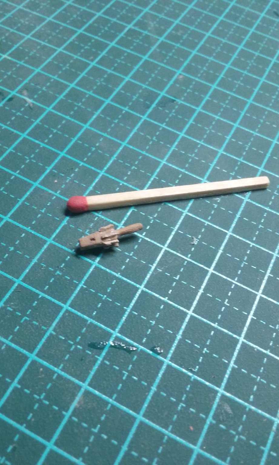
Thanks, Siggi. That's beautiful work. Now I have two different media to try when I next want to have invisible gluing. I've changed my mind about the knight for the main halyard. The Lomellina was considerably smaller than the Great Harry, and for her a two-sheave knight was enough for the main halyard. But I think for a ship the size of the Great Harry, a three-sheave knight would be more appropriate. The capstan may have had a bigger diameter to allow for more bars, but with the design I'm working from that would have needed three through-holes in the drum, which would have made for problems with the height of the bars above the deck. So I've kept it at the same size. It just needs the cleats to be trimmed and it's complete. Steven


- 740 replies
-
- 5
-
-
- Tudor
- restoration
- (and 4 more)
-
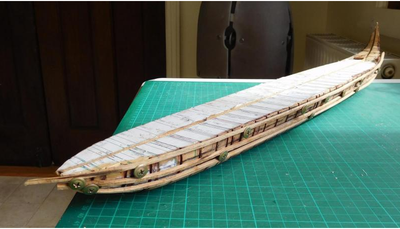
I just read the instructions. SHEESH! No wonder you're confused! Unfortunately the person who translated them into English had very little idea. My understanding of step 3 is "Nail and glue the wales to the frames indicated". So, what is a wale? It's basically a thicker, heavier plank which gives the hull greater longitudinal strength. Here's my dromon with just the wales attached (note: I built mine a different way from yours - I used a "plug" - a bit of wood the same shape as the hull and planked over that, then added the frames afterward.) and here it is fully planked and removed from the plug - you can see how the wales reinforce the planks. So look for some bits of wood that look like they'll fit the bill. Do you have a diagram which shows the wales? As for the planking, I can't really help you. The bundle of timber for the planking probably contains more pieces than the bundle for the decking. But there have been at least two build logs for the same model - and I hope they can help you. Messis also did an Amati bireme in 2015, but I couldn't find it in a search. Hope this helps. Steven
-
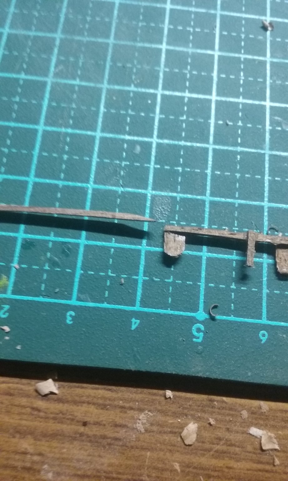
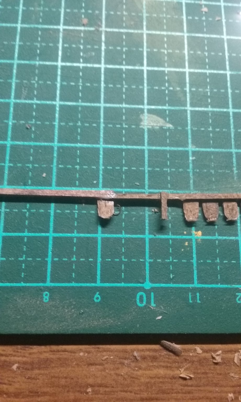
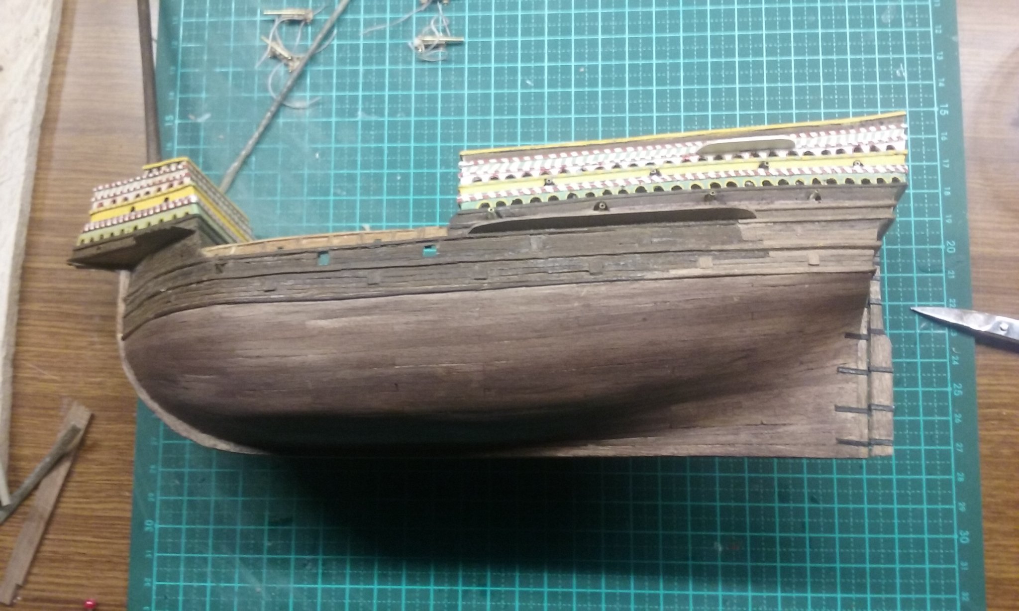
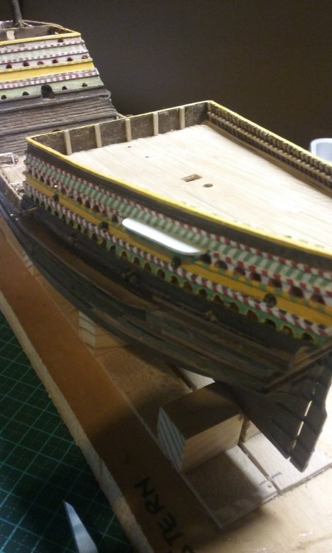
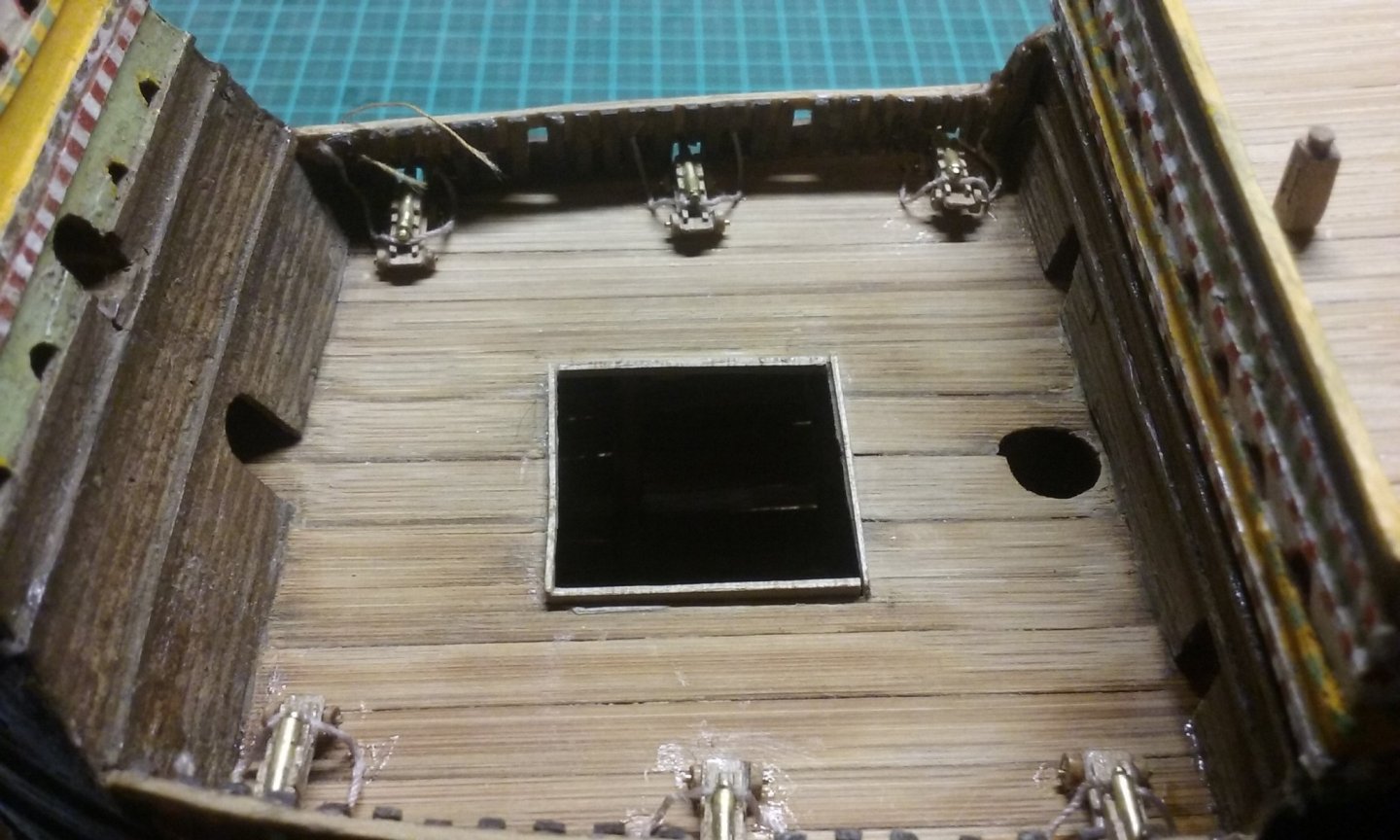
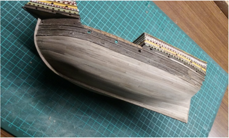
I've stained the hull below the waterline, using a mix of black and dark tan boot polish. Worked quite well. This is how it was before - just too light in colour: and finished the breechings on the cannons - a bit of a problem with glue spread everywhere - I'll have to remove the surplus. And working on the knight and the capstan for the main halyard. The capstan needs the rest of the cleats put on it before it's complete. It's based on the one from the Lomellina wreck of 1516 - nearest we have to the right time and place. I have an e-book which purports to show the Mary Rose capstan, but as far as I'm aware it was never recovered, so the e-book one must be based on speculation, so it's no more reliable than my own. And here's the knight dry fitted. I won't glue it in place until after I've threaded the lanyards through it. Otherwise I'm just making my life difficult. Steven


- 740 replies
-
- 11
-
-
- Tudor
- restoration
- (and 4 more)