


KeithAug
-
Posts
3,405 -
Joined
-
Last visited
Content Type
Profiles
Forums
Gallery
Events
Posts posted by KeithAug
-
-
On 12/27/2021 at 7:43 PM, wefalck said:
Didn't know that B&D made a table-top version of the Workmate, looks useful. I had the fullsize one for decades.
Yes it surprised me too. Must find one.
- Keith Black and mtaylor
-
 2
2
-
On 1/2/2022 at 6:15 PM, Brett Slater said:
The plans i used were drawn by Harold Underhill, i had a link to the website where they could be purchased but this no longer seems to work.
Hello Brett, nice work on the hull, it turned out very clean and given your plasticard construction technique I am impressed it turned out so well. It would have been good to see more of the process. I too considered building Servia a few years ago but abandoned the plan because my fingers and eyes don't cope well with detail at 1/192 scale. I had a look at Harold Underhills plans and like you have recently found these difficult to find following the demise of Model Dockyard. I wonder if other members know of an alternative source for Harold Underhills extensive range of plans?
- Brett Slater, Keith Black and mtaylor
-
1
-
 2
2
-
Happy New Year Eberhard. You have been busy over Christmas. I loved the rifles and the sky lights are a masterpiece of miniaturisation.
- Keith Black, FriedClams, mtaylor and 1 other
-
4
-
Happy new year to you all. Christmas went off to plan with all the immediate family making it home disease free. We were lucky.
Thank you to all of you who visited my posts over the festive season and a particular thank you for the comments and likes.
I managed to get some work done on Germania but it was a bit erratic which unfortunately means the posts will be a bit rambling.
Most of the time went towards making the main and foremast booms. They are both circular with tapers towards each end. I won't bore you with the details but basically I turned down dowel and then sanded tapers on each end.
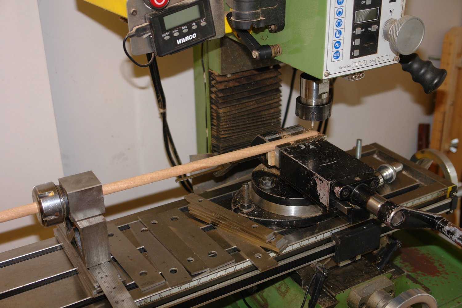
Before sanding the tapers I machined the dowels to take the end fittings and tracks for the sail sliders. I used my mill with the dowel clamped in a square collet block to facilitate machining of the features at right angles.
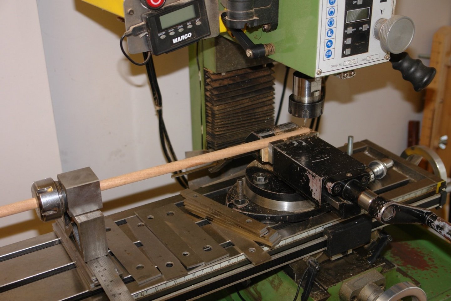
Slots were cut using end mills for the track and gooseneck attachment brackets. The high attachment features were filed to shape and drilled.
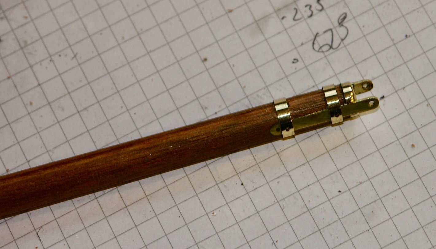
Hoops were turned, drilled and slipped into place.
The track was made from model railway train track. This was glued into the axial slot previously machined.
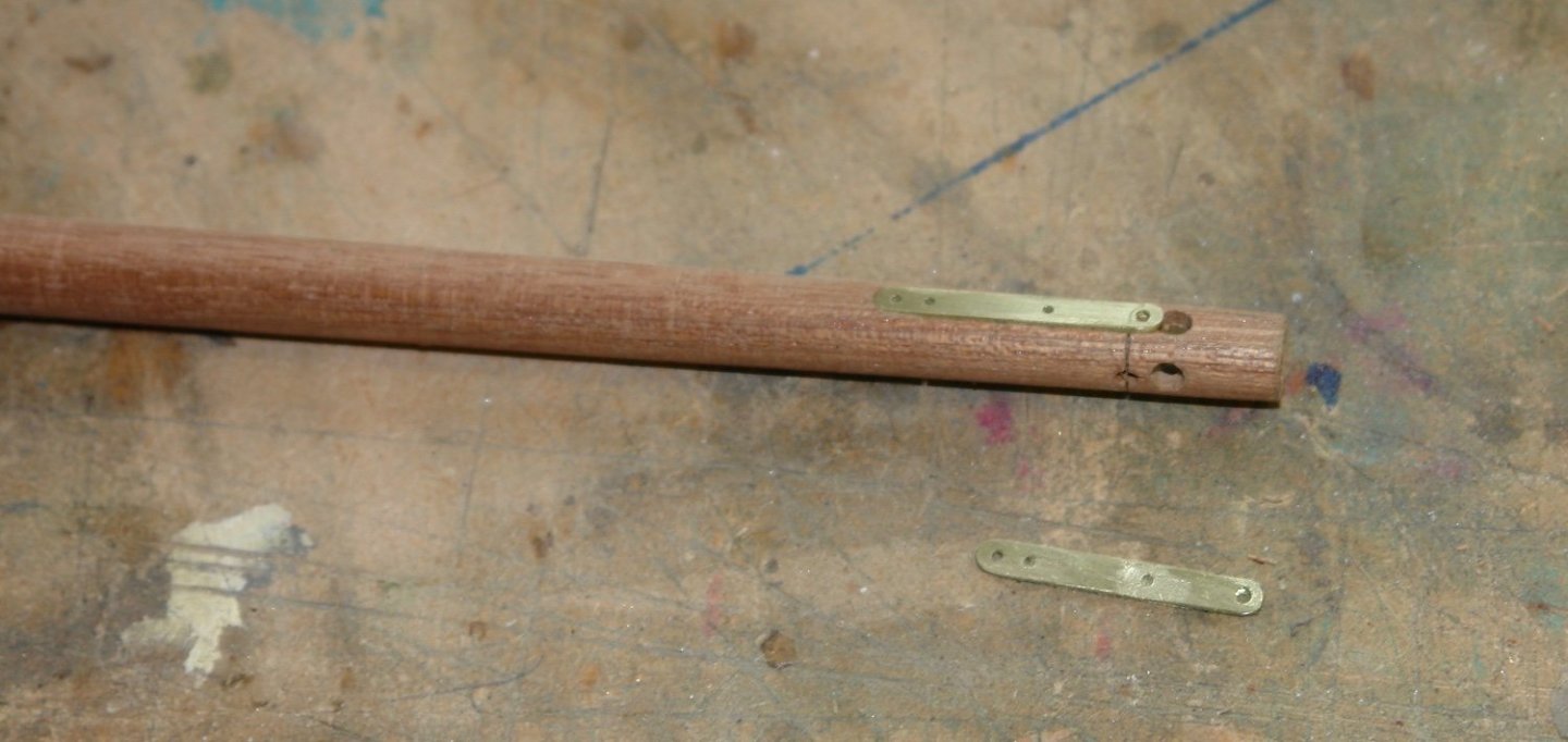
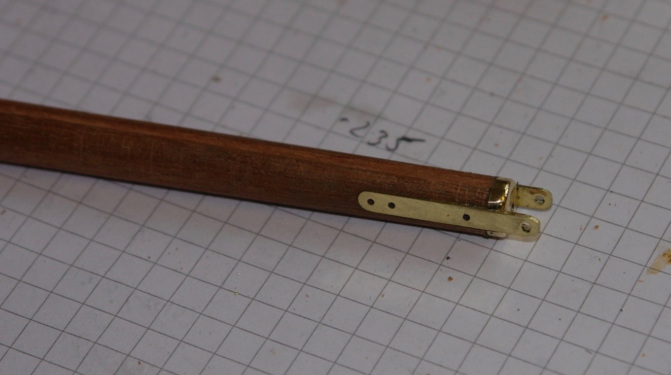
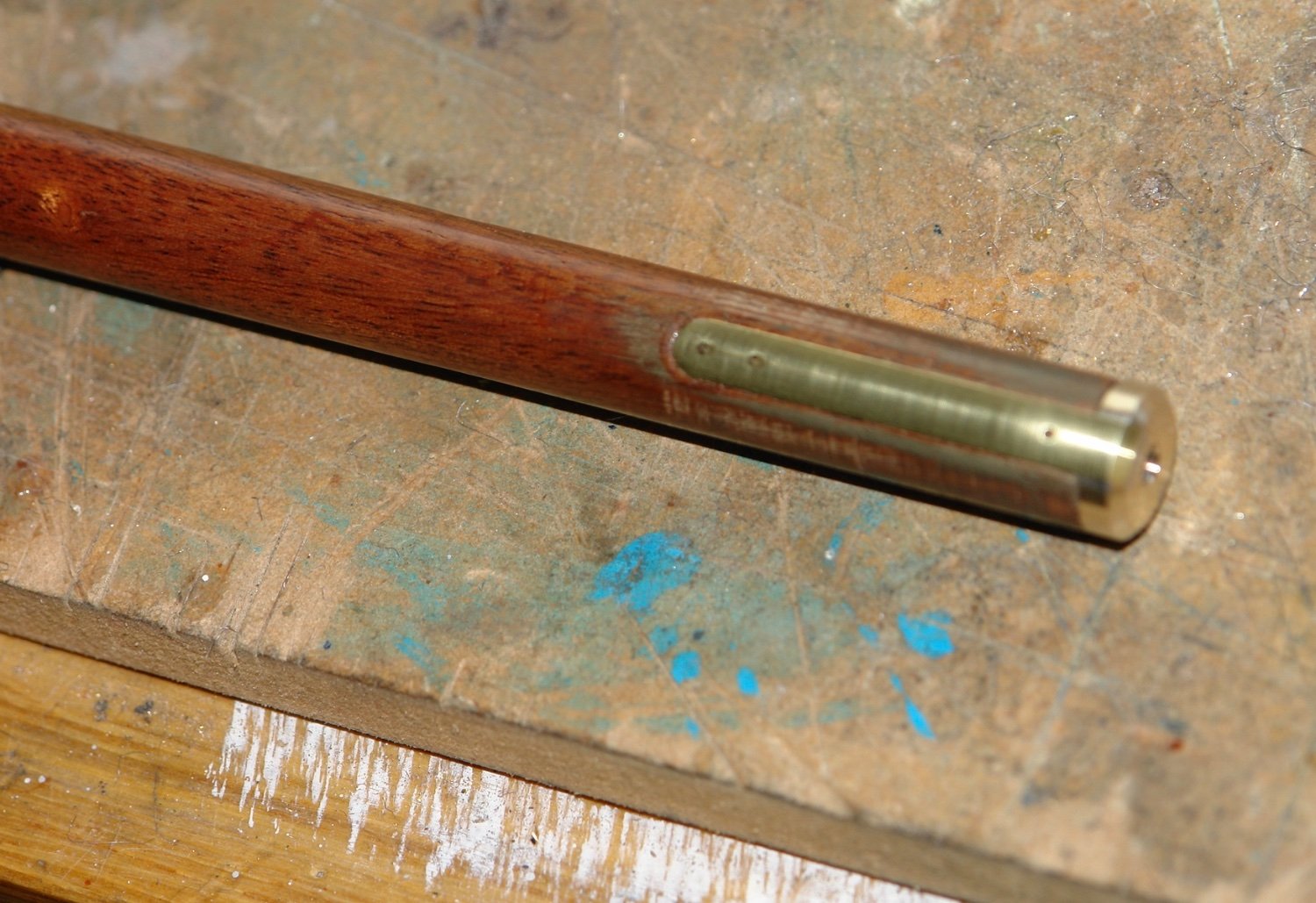
A few more shots follow showing the details of the end bracket fabrications.
Once the brackets were fixed in position the outer surfaces were rounded to match the curvature of the boom.

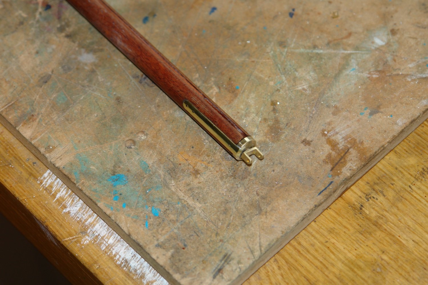
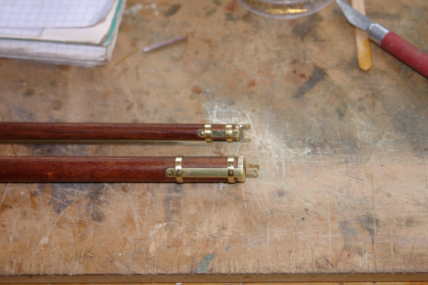
The hinges were made and attached to spigots which inserted into axial holes in the booms.

And then the hoops were positioned and fixed with brass pins.

-
On 12/19/2021 at 6:03 AM, Dr PR said:
I searched through Navy electronics manuals and found photos and dimensions for most of them.
Yes I tried this but one or two items were so pixilated that I couldn’t identify anything. Not to worry sometime guessing is a reasonable strategy. Thank you for commenting.
To all of you who have visited, commented on or liked my work over the past 12 months I wish you a Merry festive season. All the best to you and your loved ones.
- FriedClams, Keith Black, mtaylor and 4 others
-
6
-
1
-
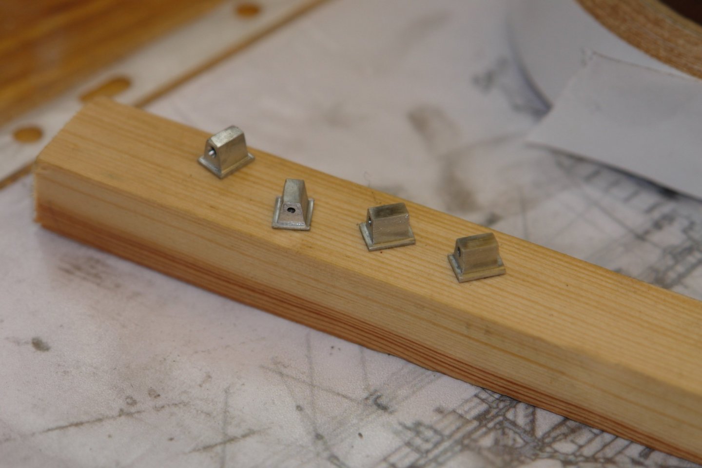
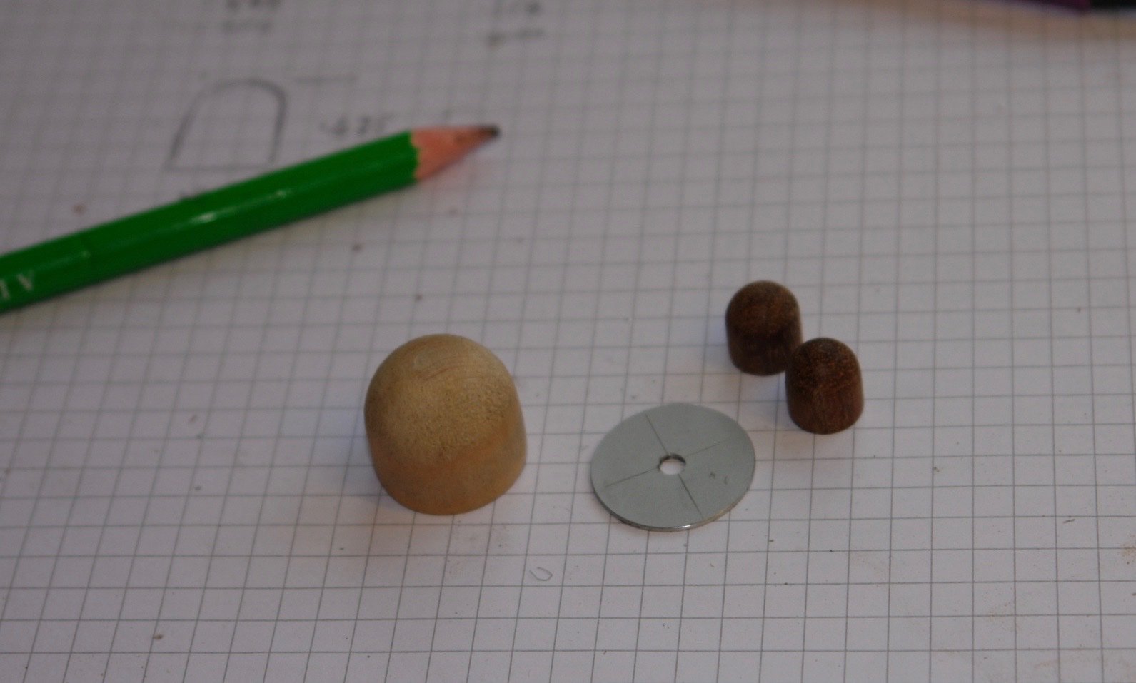
Just the briefest of updates on a few more additions for the crosstrees.
The crosstrees are festooned with various appendages, not all of which are clear in either function or form. The photos lack clarity as to anything but basic shapes.
The 3 domes were perhaps the easiest to interpret. These were turned from wood with the base flanges turned from aluminium - formerly an MacBook Pro case.
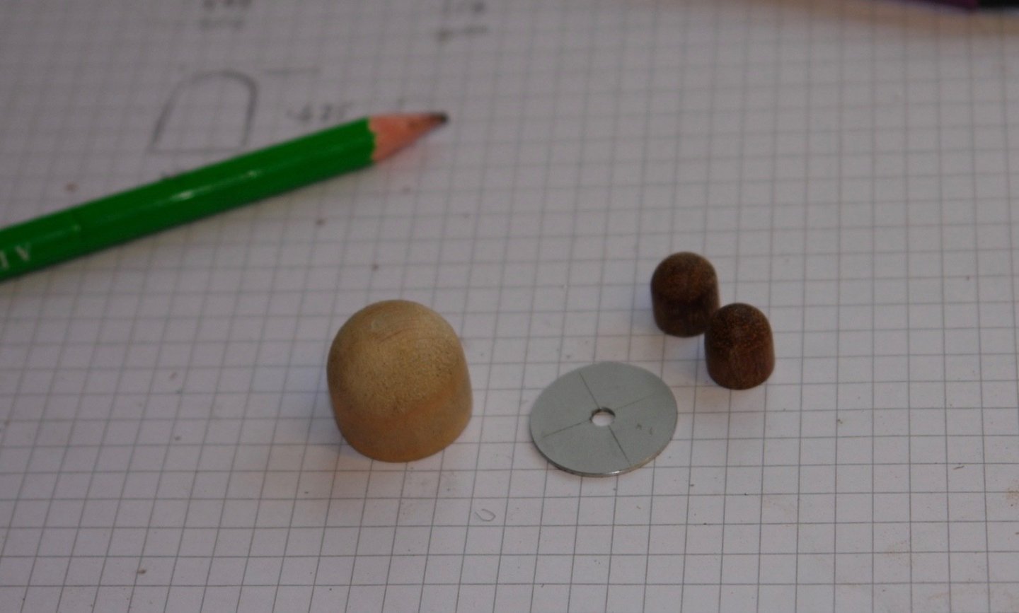
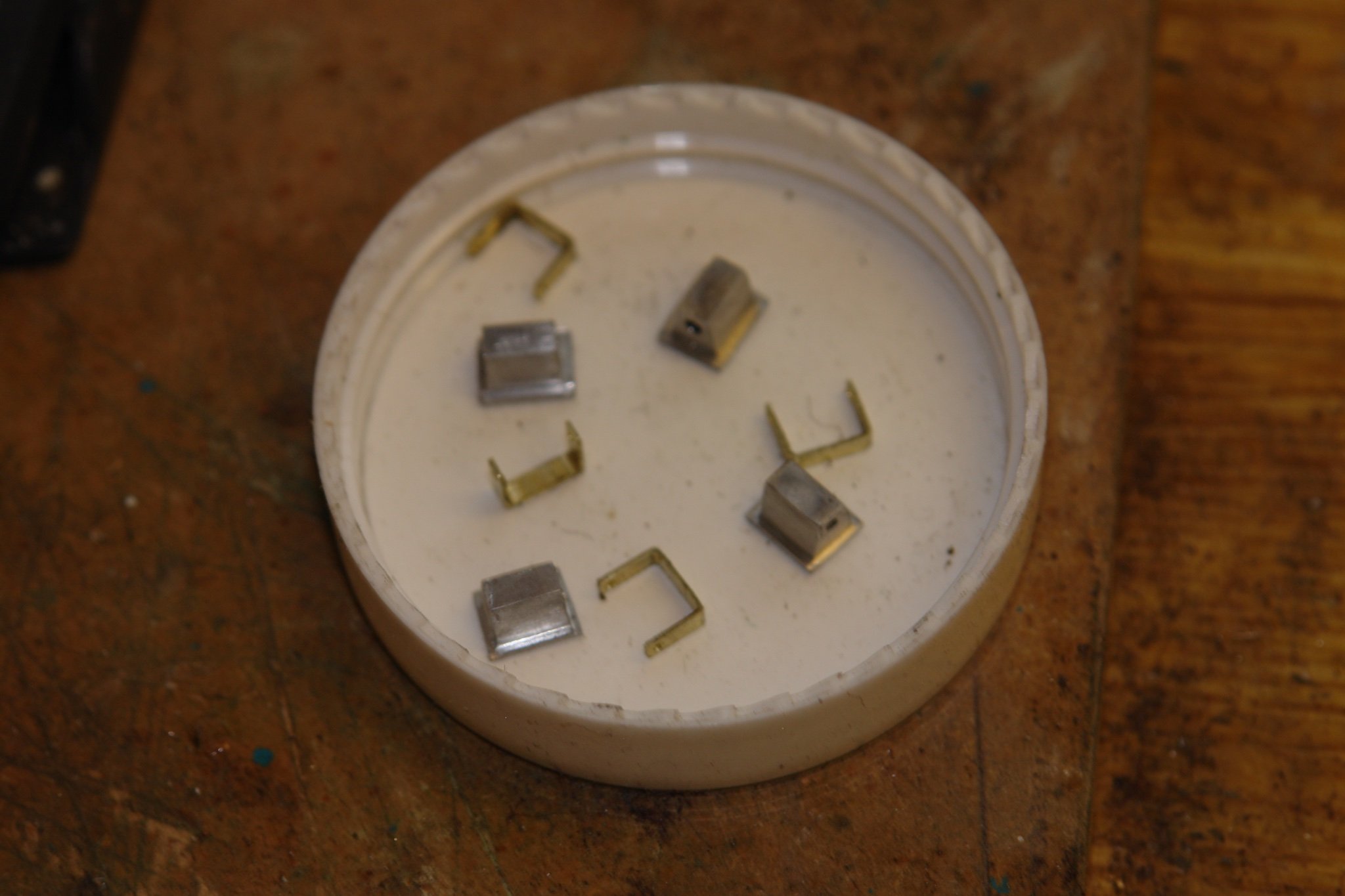
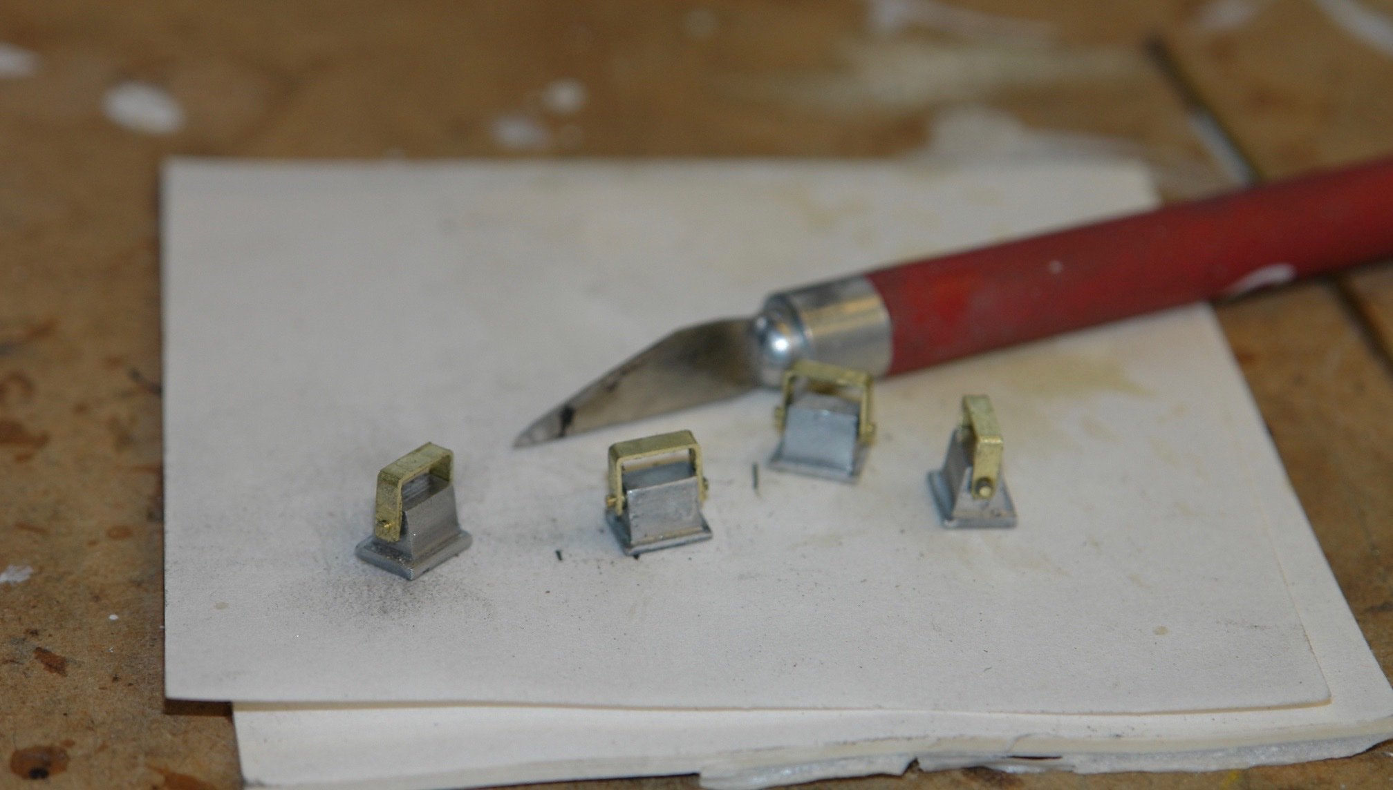
The deck lights were also easy - milled from aluminium with brackets formed from brass.


- mtaylor, G.L., GrandpaPhil and 13 others
-
16
-
On 12/13/2021 at 4:31 PM, wefalck said:
but shouldn't the antenna sit in height more or less between the two rings
Eberhard - Sometimes I get too close to things to see the obvious. Yes it is about .1" too high - fortunately easily modified.
Thank you Druxey, Geert, FF, Pat, Keith.
- Keith Black, mtaylor, Retired guy and 1 other
-
4
-
-
Deceptive use of actors will confuse many to think it is the real thing. I assume it is the model I'm looking at??????
- FlyingFish, Rik Thistle, FriedClams and 1 other
-
4
-
Thank you Keith and FF and thanks to those who have liked my work.
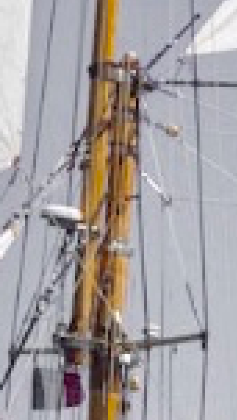
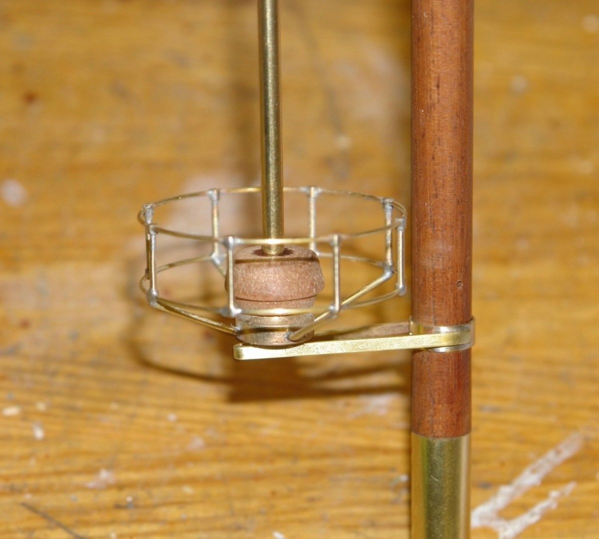
I spent the weekend doing a bit more work on the mast appendages, specifically the main mast radar. The radar is protected by a circular guard and by the look of it this has gone through a process of evolution. The photograph below shows the feature (blue arrow).
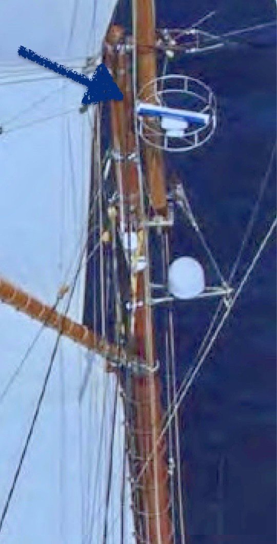
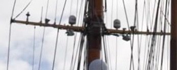
But it hasn't always looked like that - here is a reduced version:-
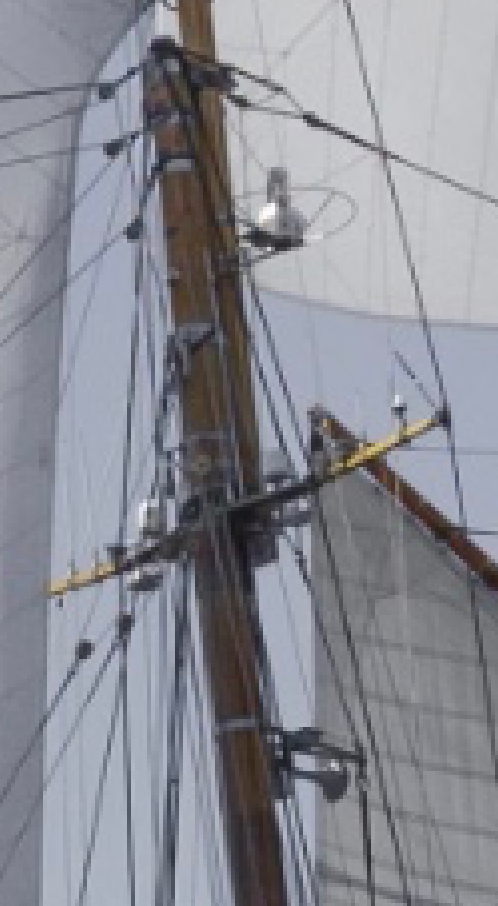
Sometimes it disappears altogether:-
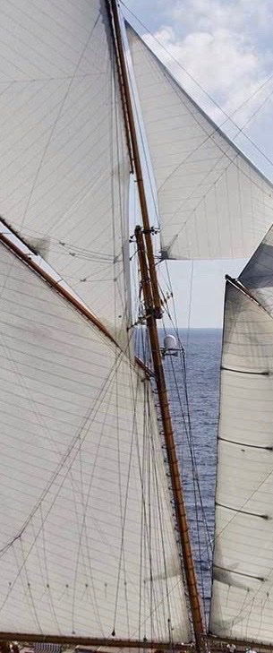
My guess is that the radar has been attacked by the rigging a number of times - presumably an expensive experience.
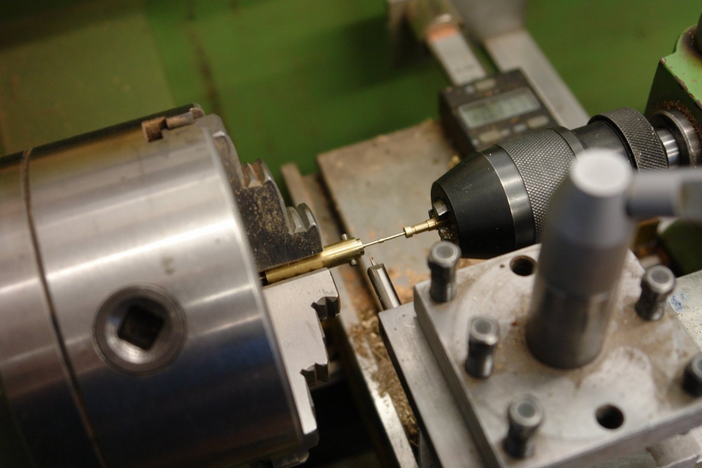
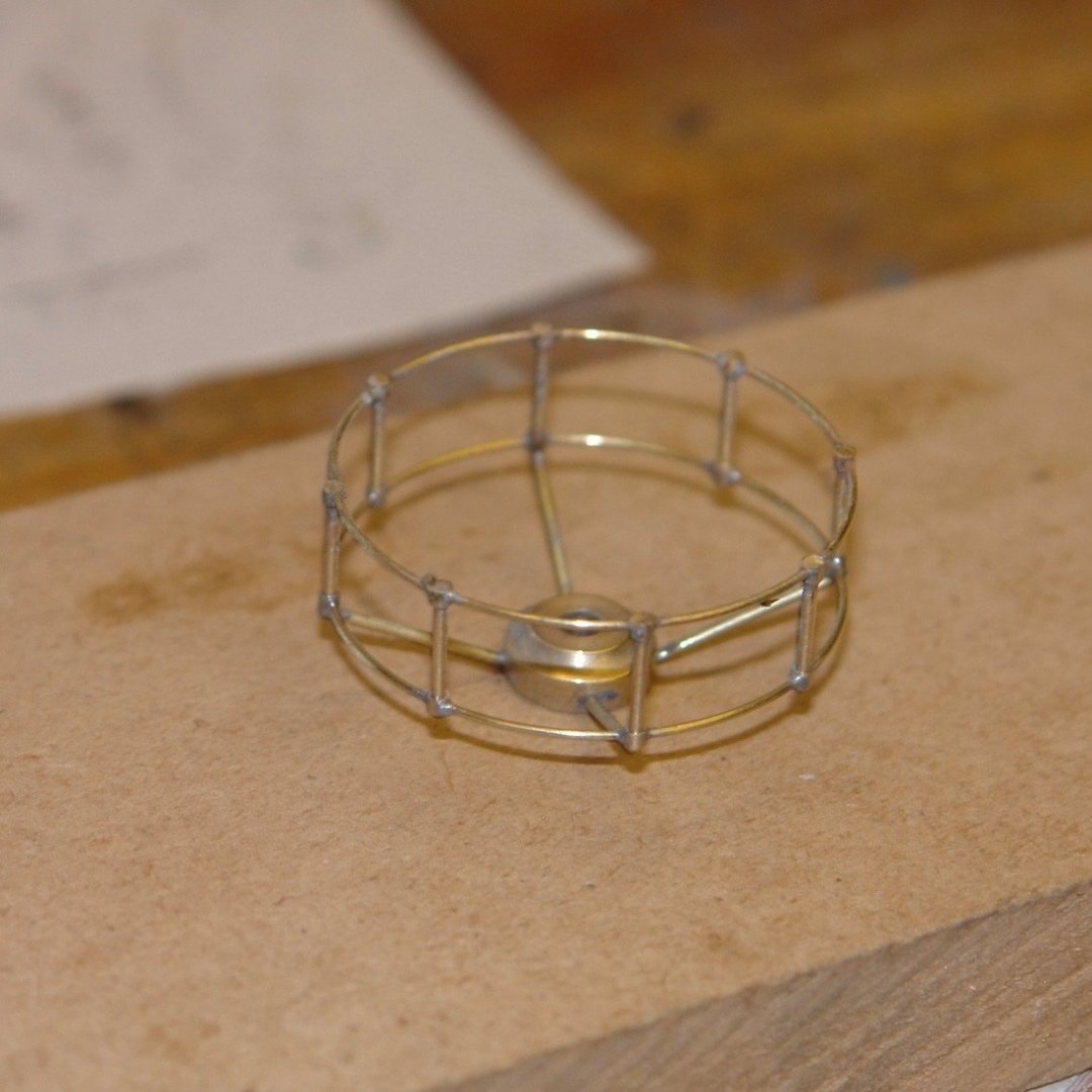
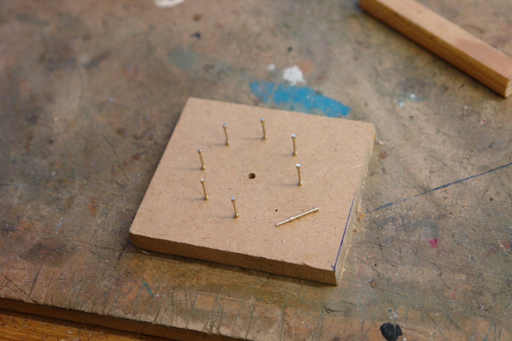
I decided to build the double ring version which scales 1.5" diameter. I started by turning the 8 vertical posts. These were turned from 1/16" brass rod and cross drilled at two positions to take the 1/32" circular rails. My lathe is a bit too big for this size of turning so I needed to improvise.
Making the fence required a jig - made from MDF and drilled to take the 8 posts. The posts have a sacrificial spigot to locate them in the jig - see the yet to be inserted post, bottom right in the next photo.

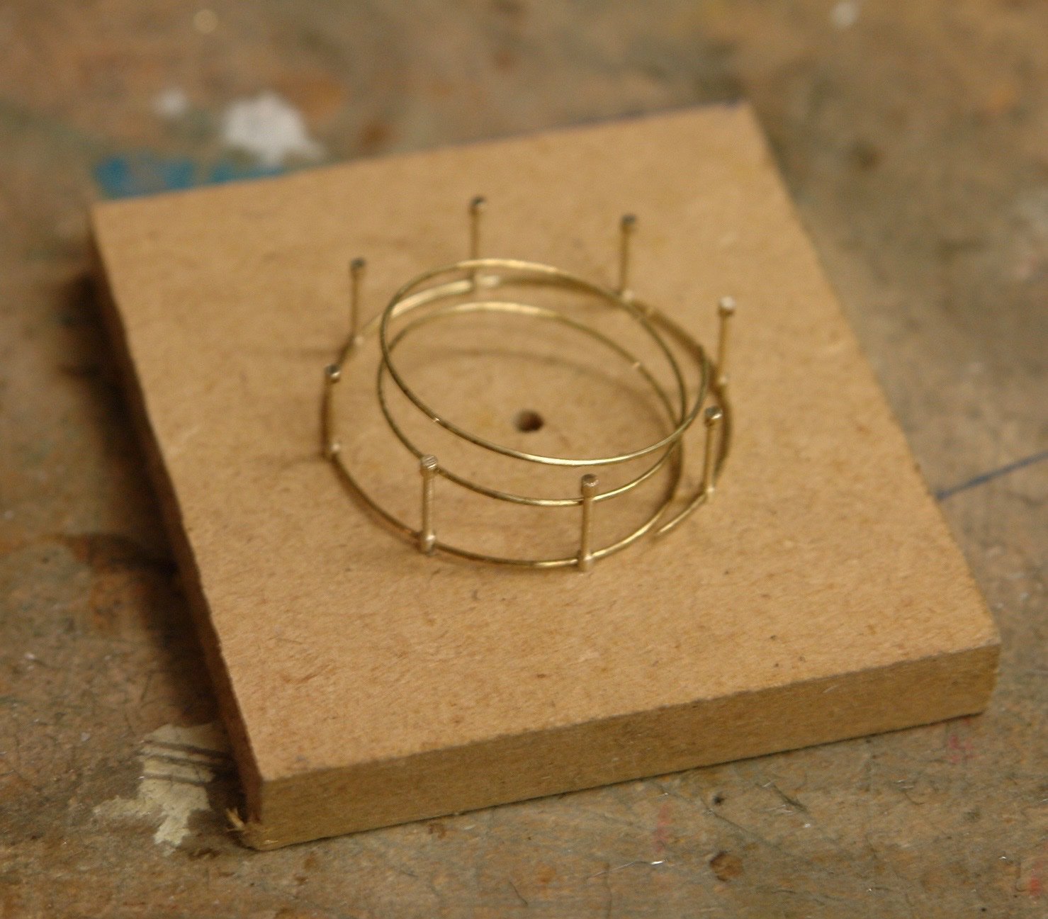
I then wound about 3 coils of 1/32" wire around a circular mandrel of about 1" diameter.
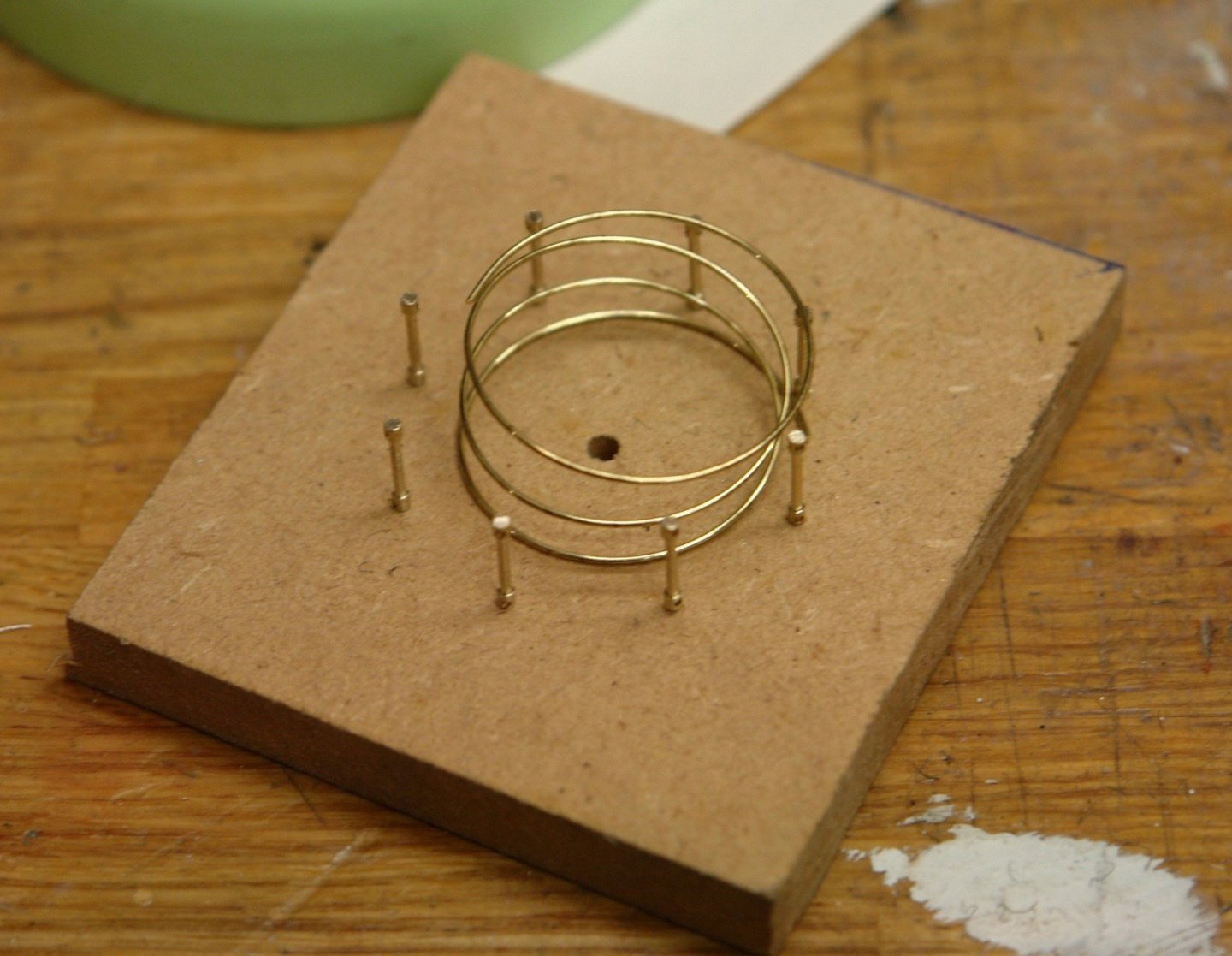
This was threaded through the pre-drilled holes in the posts - the wire expanding in diameter as the treading proceeded.

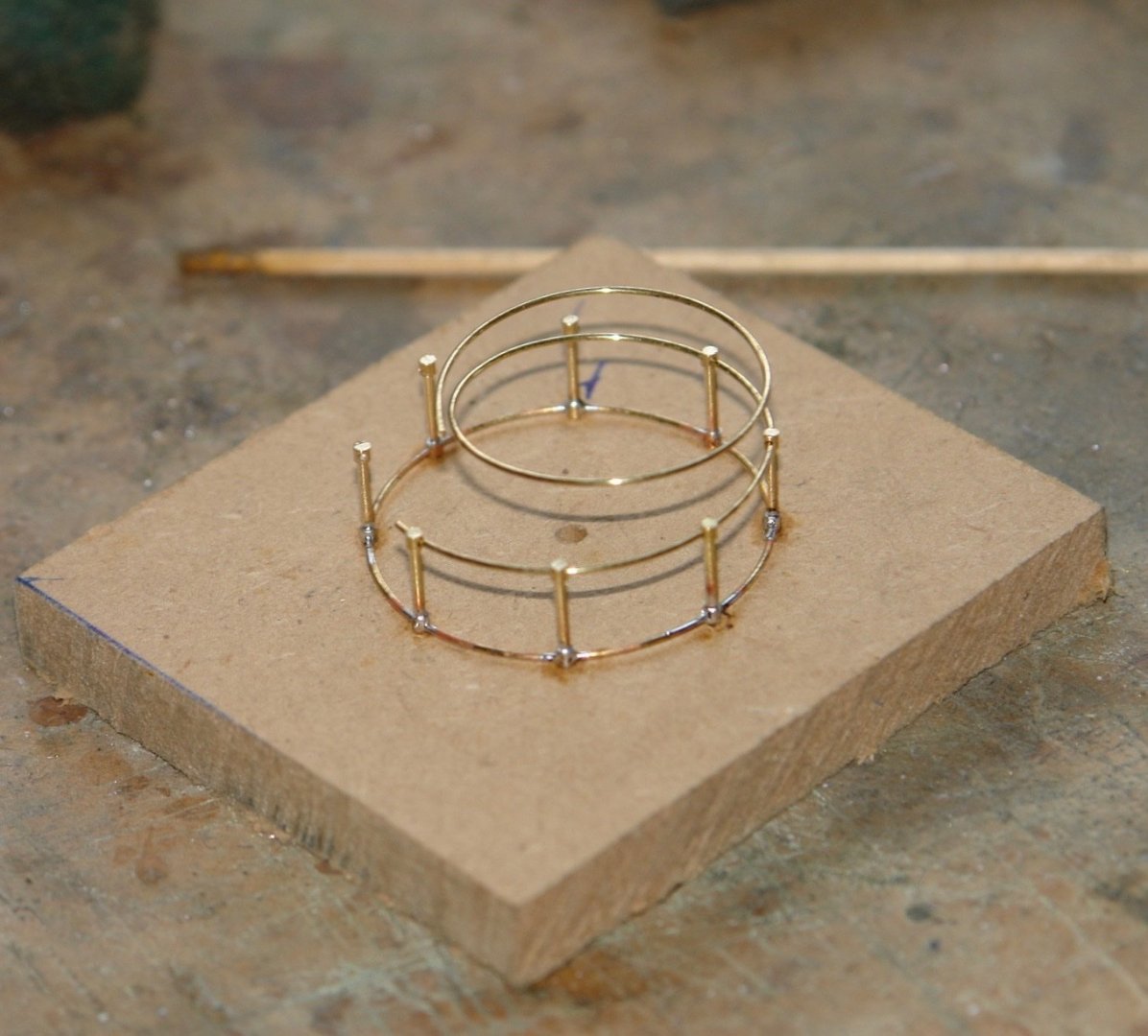
Once the complete hoop was formed it was cut to length and the join was lost inside one of the post holes. The ring was then soldered in place.

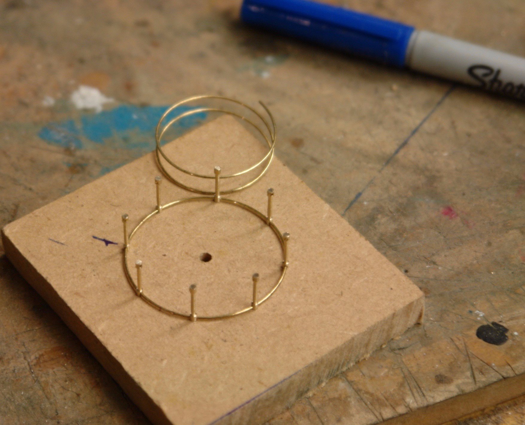
This was then repeated for the second ring.
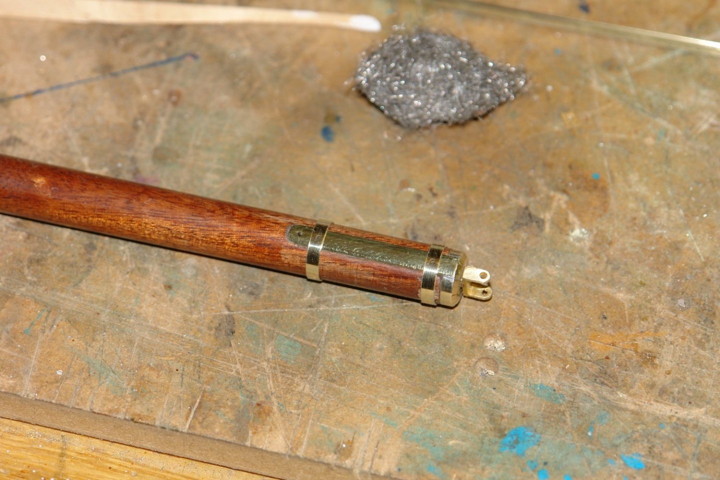
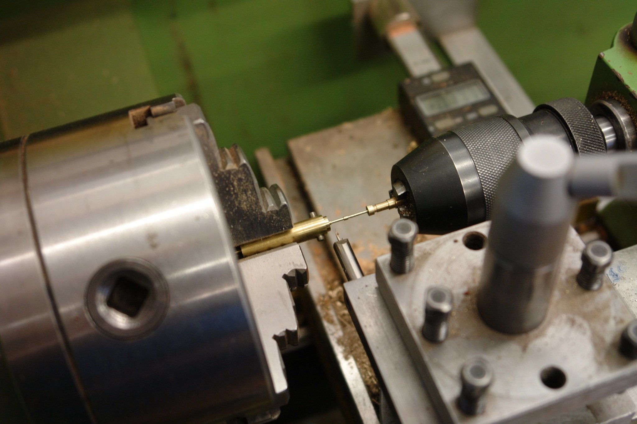
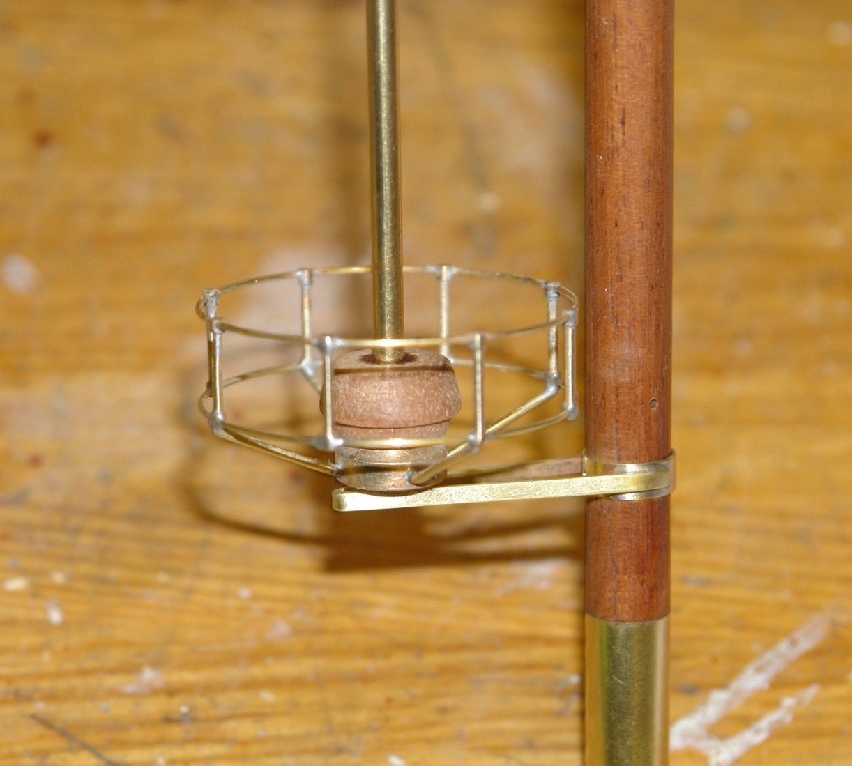
The central boss which holds the radar was then turned and milled to take 4 support arms. These were soldered in place.

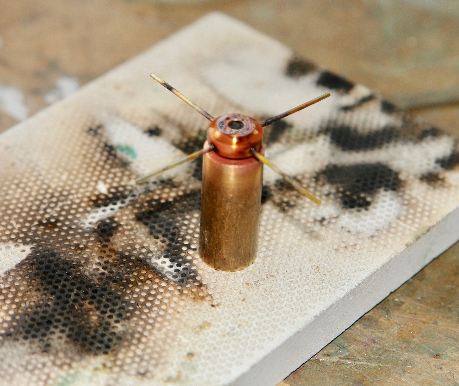
The pins were then bent to the correct angle. The boss is actually brass although you could be forgiven for thinking it is copper.
Once cleaned up and parted off it looked like brass again.
The reason for the central hole in the MDF jig now becomes obvious - it locates the boss while soldering the 4 arms to 4 of the posts. The drill made a useful location peg.
With the assembly complete it was eased off the jig.
The location pegs were then removed with side cutters and the connection points cleaned up.
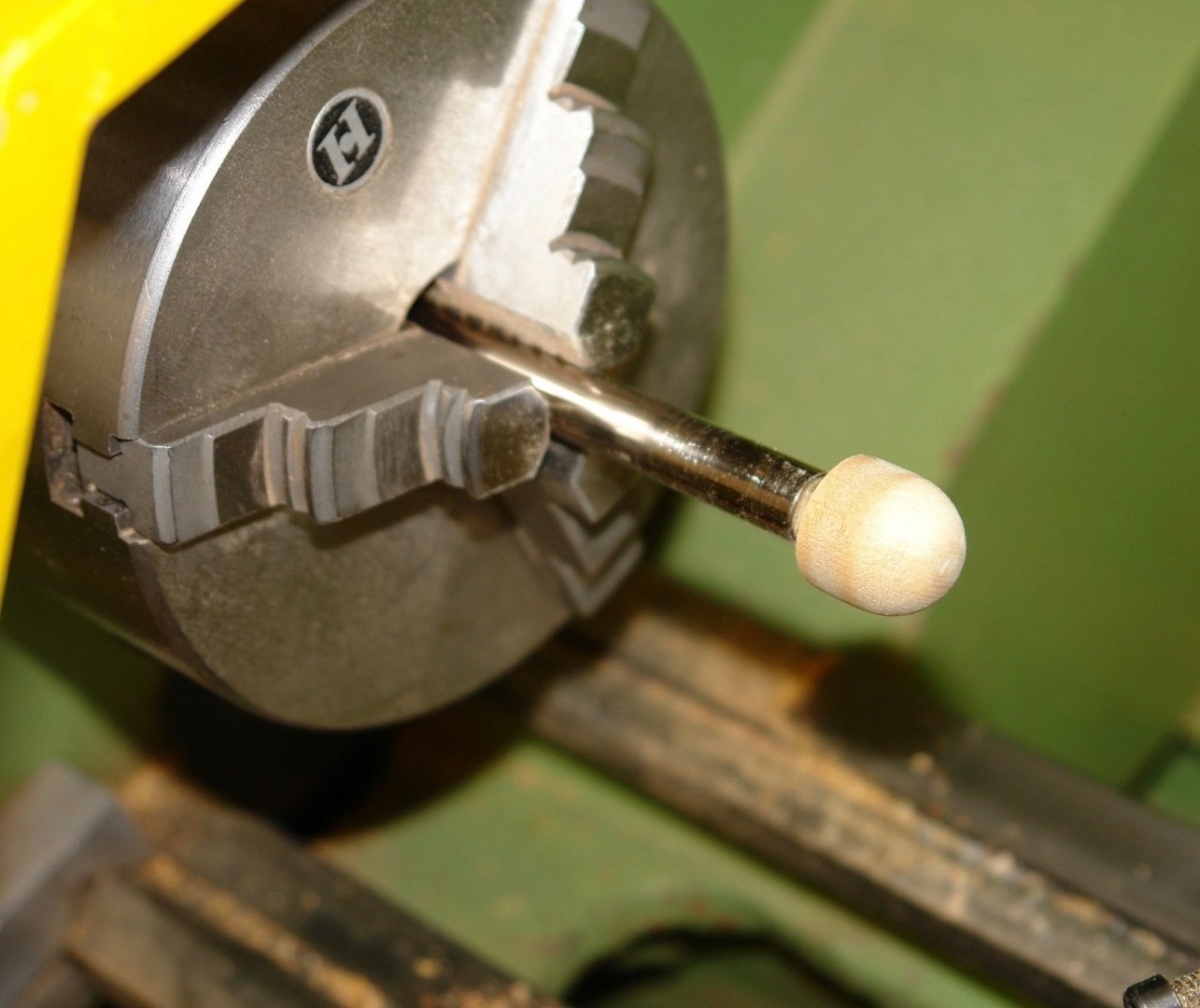
The motor housing for the radar was turned from a piece of hardwood.
The antenna was milled from a piece of aluminium.
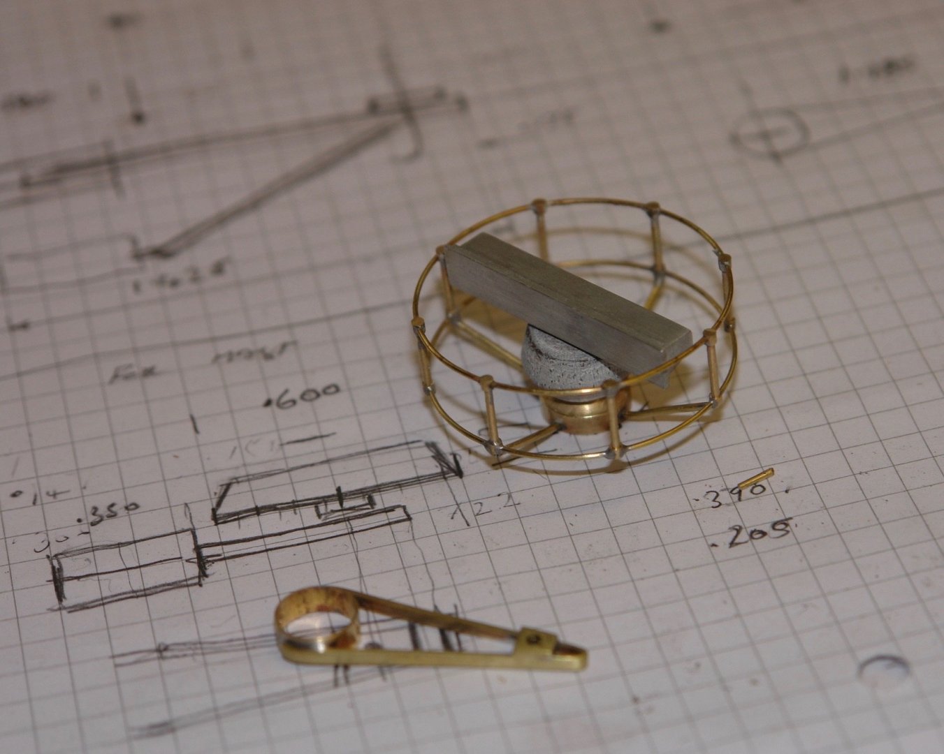
I decided to paint the guard silver.
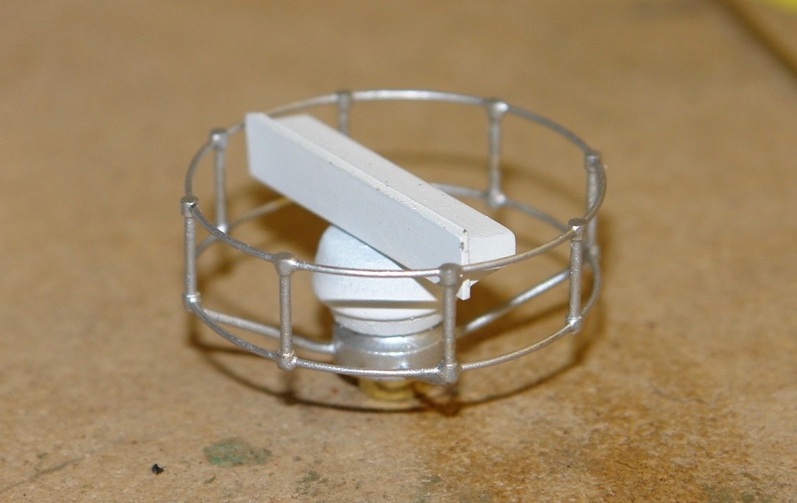
I hadn't noticed the white paint chips until I took this picture, Grrrrr!
-
On 12/7/2021 at 11:03 PM, Keith Black said:
Geez, I just added those up and the total is 475! I'm only 20% there.
Excellent work but i think we all need to get a life. Having delivered the tutorial you could farm the work out to your audience and check how well we have learned.
-
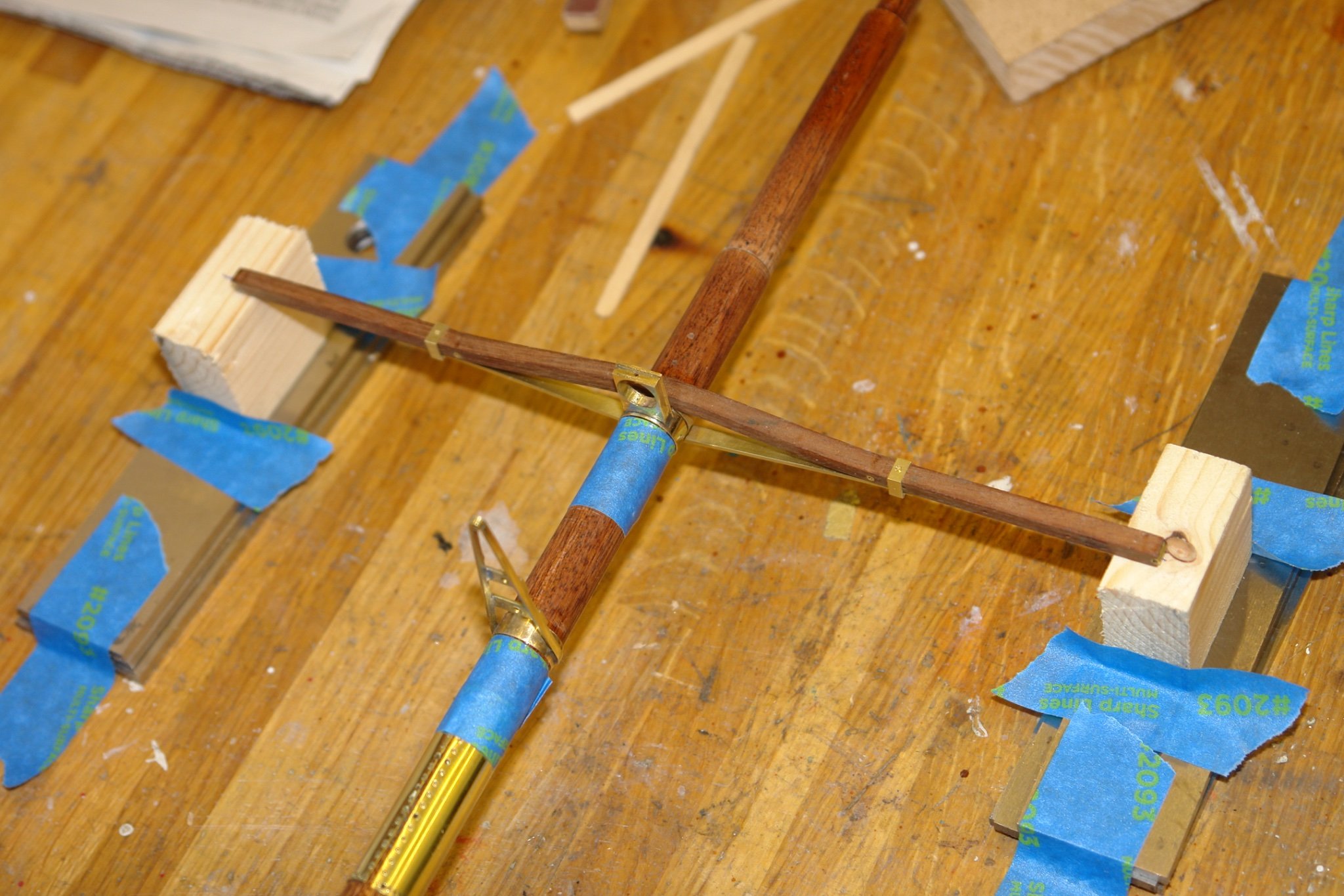
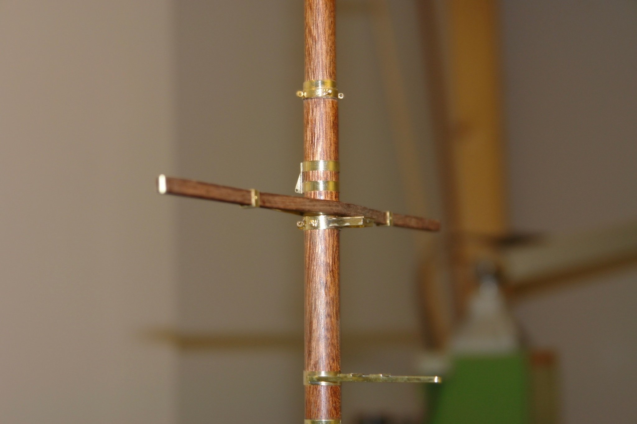
I am still working on the main and fore masts. A lot of the last few days has gone into set up and axial alignment of the lower and upper masts. I started by glueing and pinning the cross trees to the lower masts. With the cross trees correctly positioned I used them supported on shims (milling parallels) to set the lower mast off the bench. With this set up I used a steel rod to align and fix the rotational positions of the upper mast support brackets. These brackets were then glued and pinned.
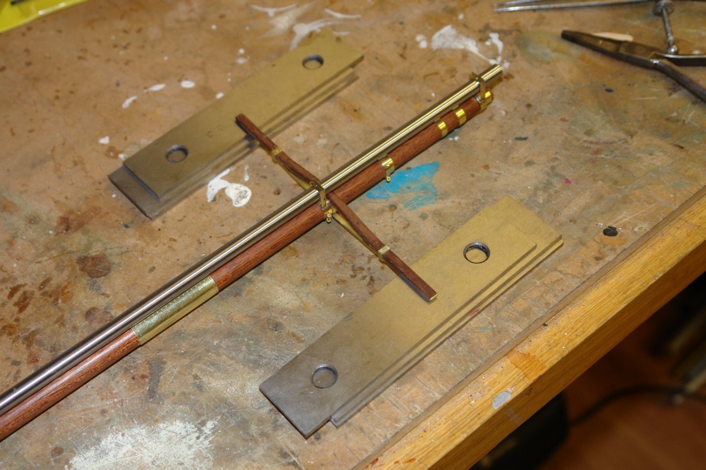
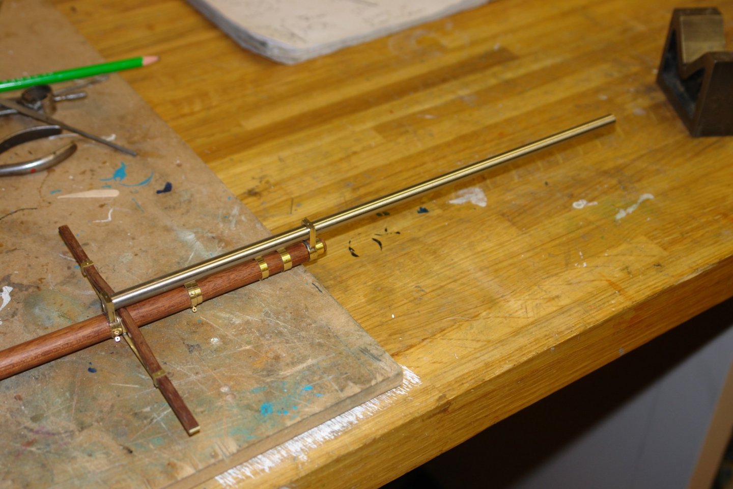
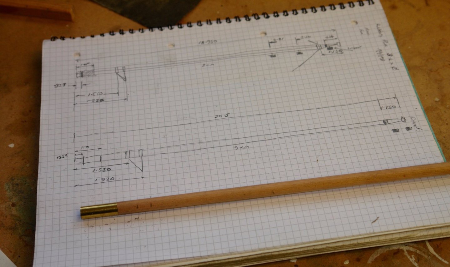
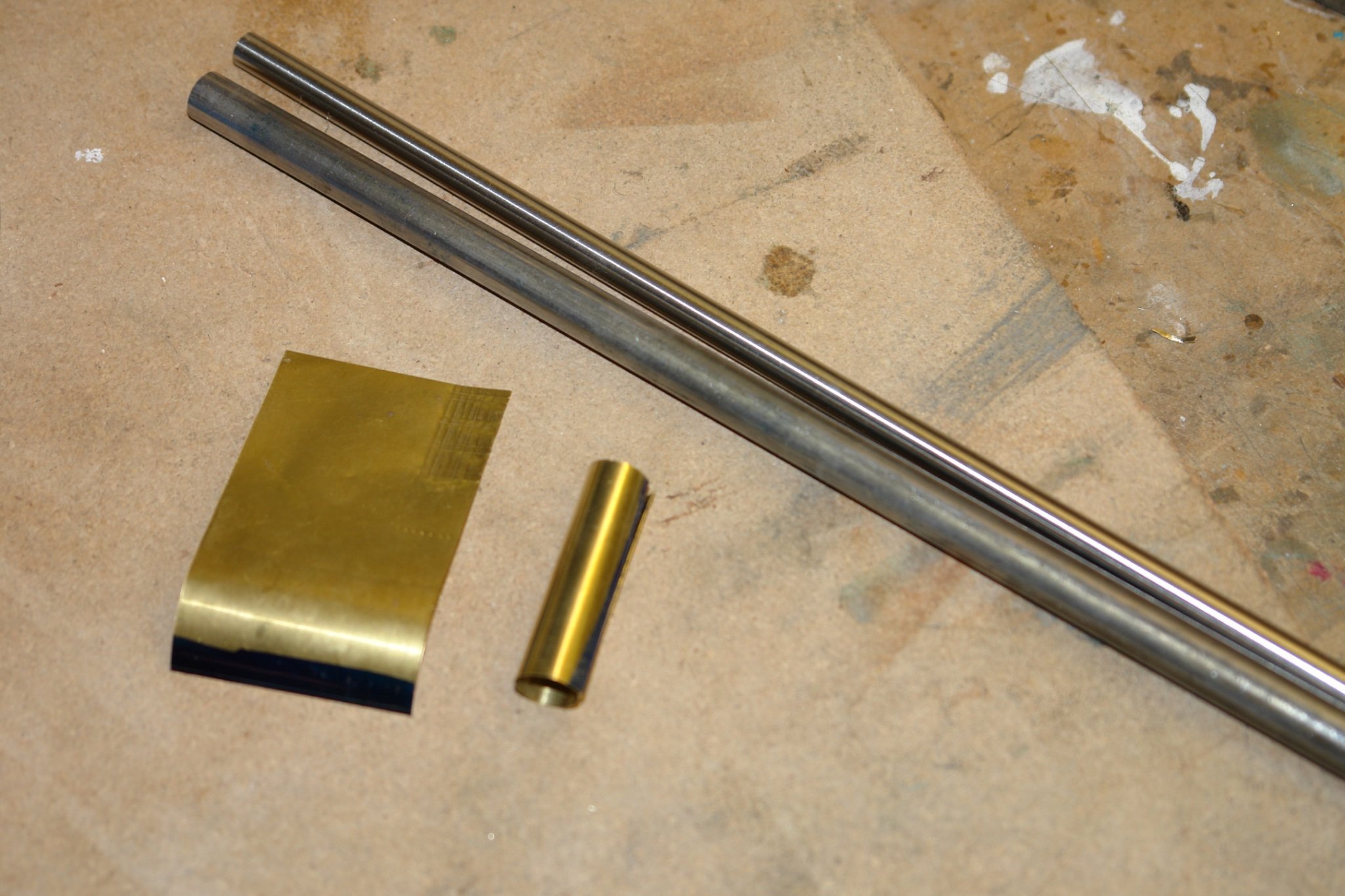
I then made the upper masts with their various hoops. Both upper masts are similar differing slightly in lengths and diameters.
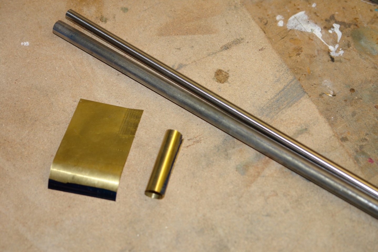
They taper at the upper end and have a parallel section that slides in the brackets. The photo below shows the sizes and one of the upper masts in preparation.
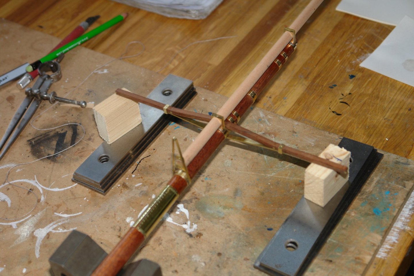
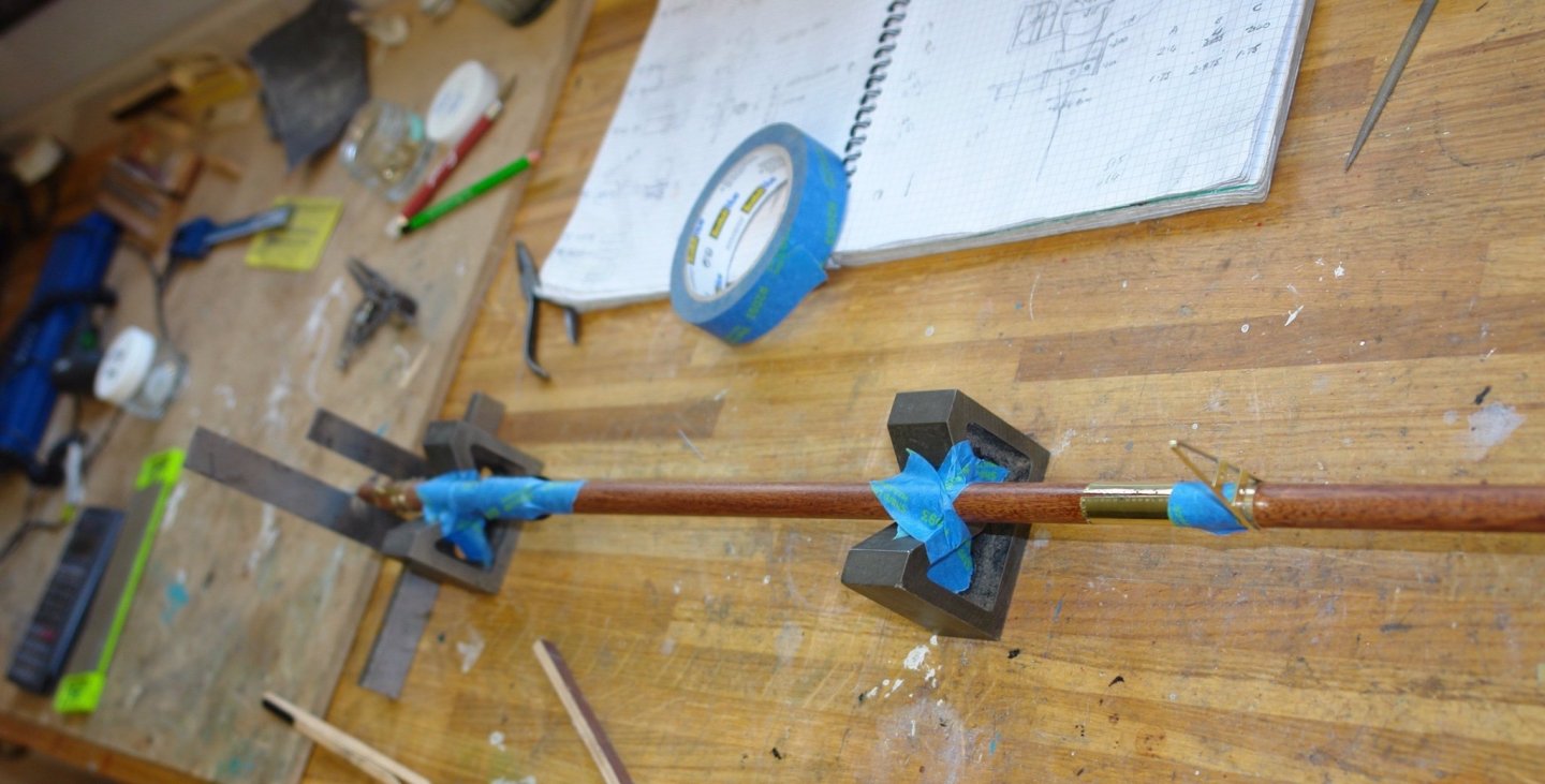
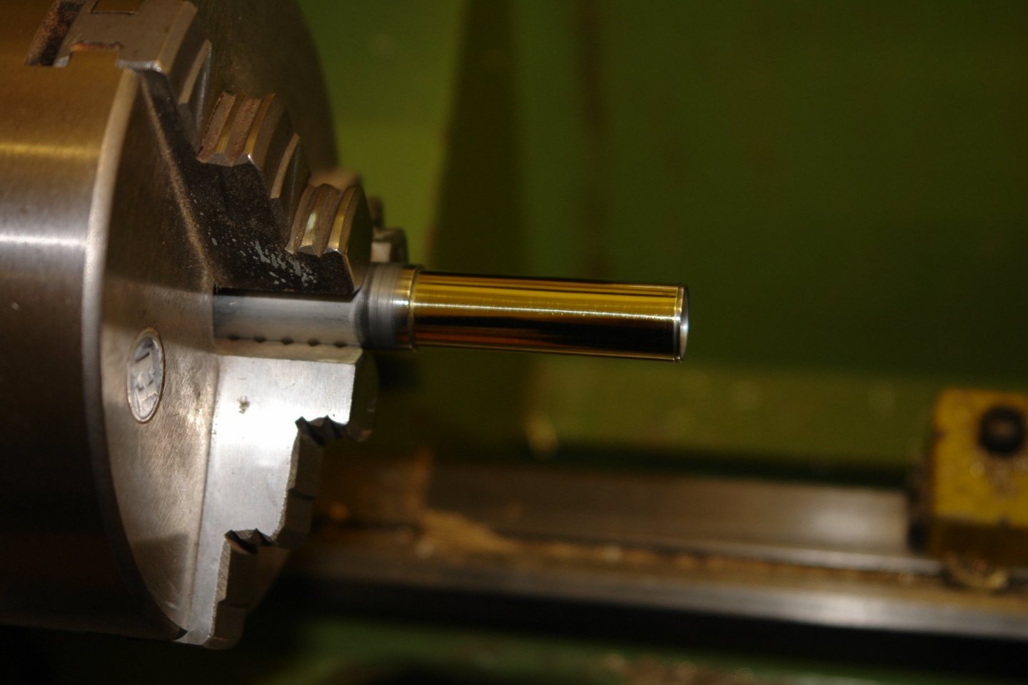
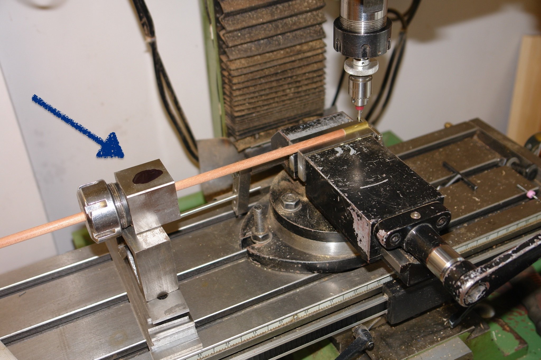
Drilling cross holes in the masts at right angles can be a bit tricky and my short cut for doing this is to clamp a collet block to the mast and shim up to it (blue arrow below) thus allowing me to index it round through 90 degrees.
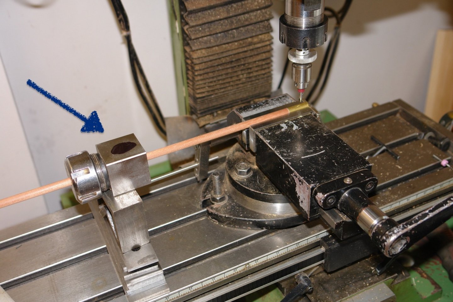
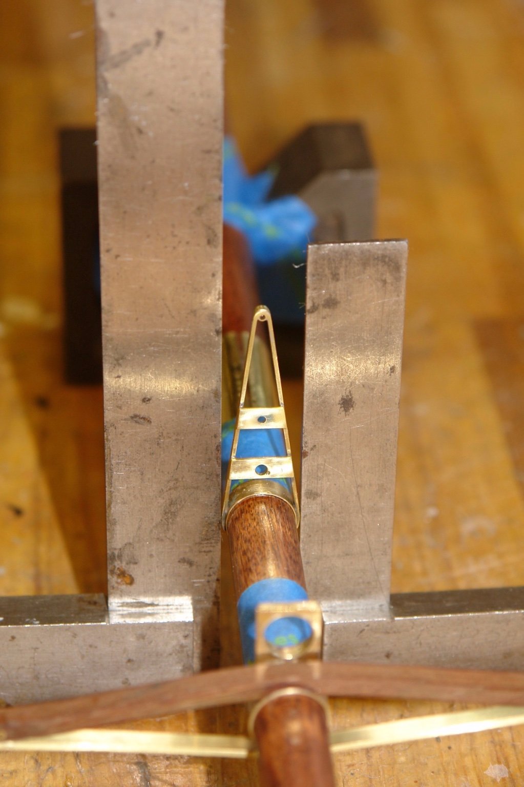
Then it was a case of more setting using various "V" blocks, scrap wood and lashings of blue masking tape.

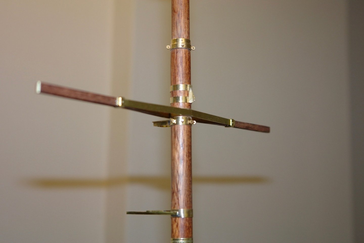
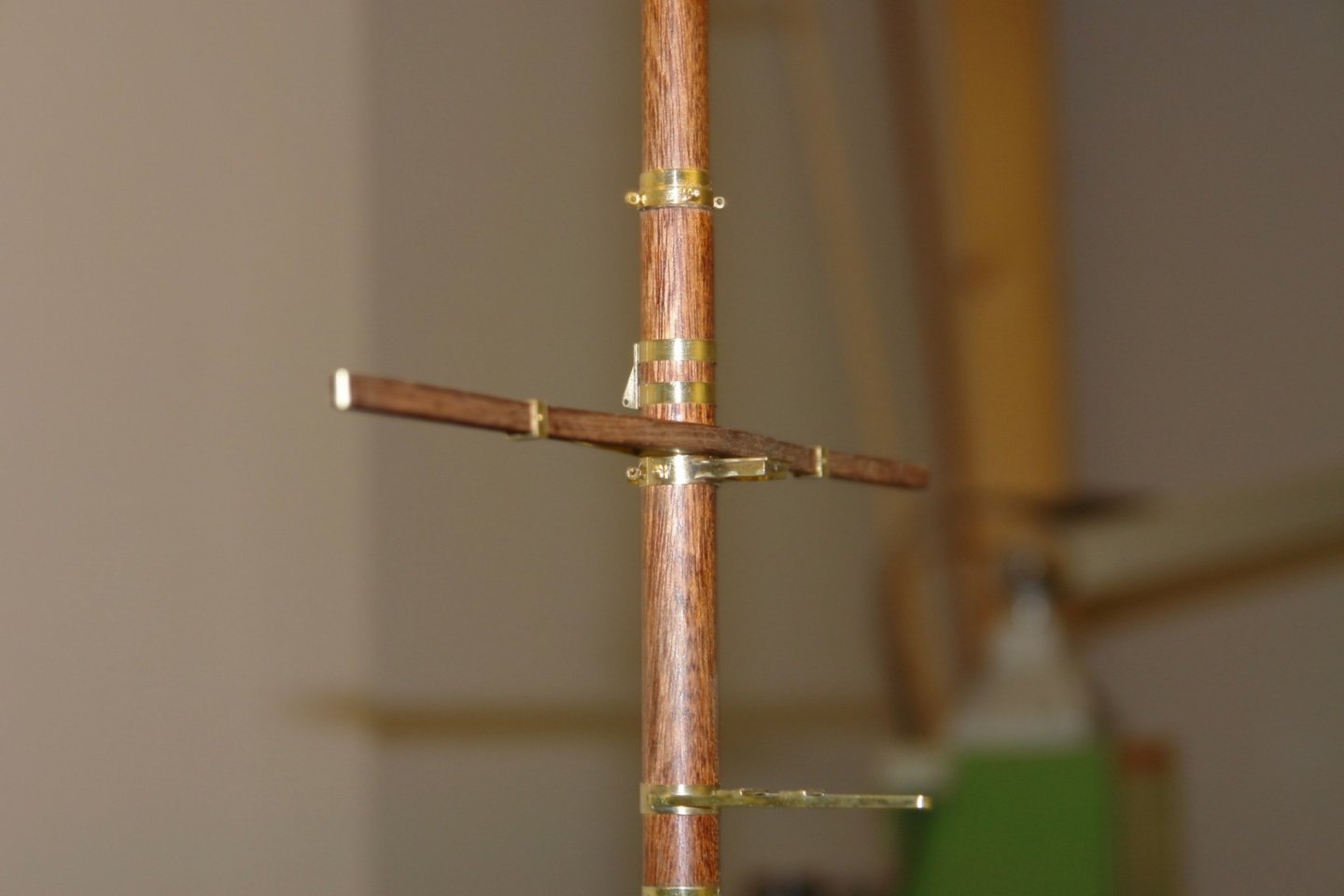
With the masts held in position I set and fixed the radar support frames etc.

The main and fore masts are now assembled but still have a good number of fittings to add.
The workshop isn't much fun at the moments hovering around 8 deg C (46 deg F). About 3 hours a day is all that I can stand so progress is slow.
- FriedClams, BANYAN, Bedford and 12 others
-
15
-
-
Lovely work Valeriy. Vey impressive rails - so crisp and clean.
- Valeriy V, lmagna, Keith Black and 2 others
-
5
-
On 12/6/2021 at 8:05 AM, wefalck said:
it is actually surprisingly easy
Eberhard - thank you for the advice - excellent portholes.
- Keith Black, mtaylor and FriedClams
-
3
-
-
-
-
Your build detail continues to delight. Are you planning to put bite marks on the stern?
- mtaylor and FriedClams
-
2
-
20 hours ago, FlyingFish said:
If you go on like this I'm going to have to buy a lathe and mill
I think you do alright without. however Christmas is coming!
Thank you Druxey.
- FriedClams, Keith Black and mtaylor
-
3
-
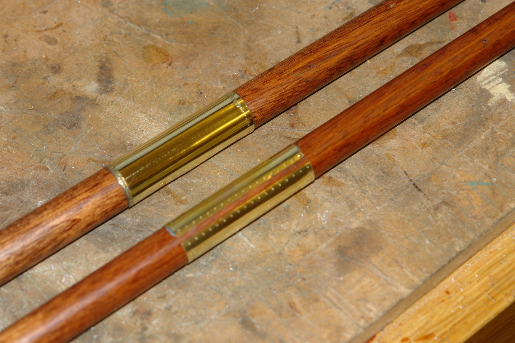
Thank you Pat but I need to curb my deviant tendencies.
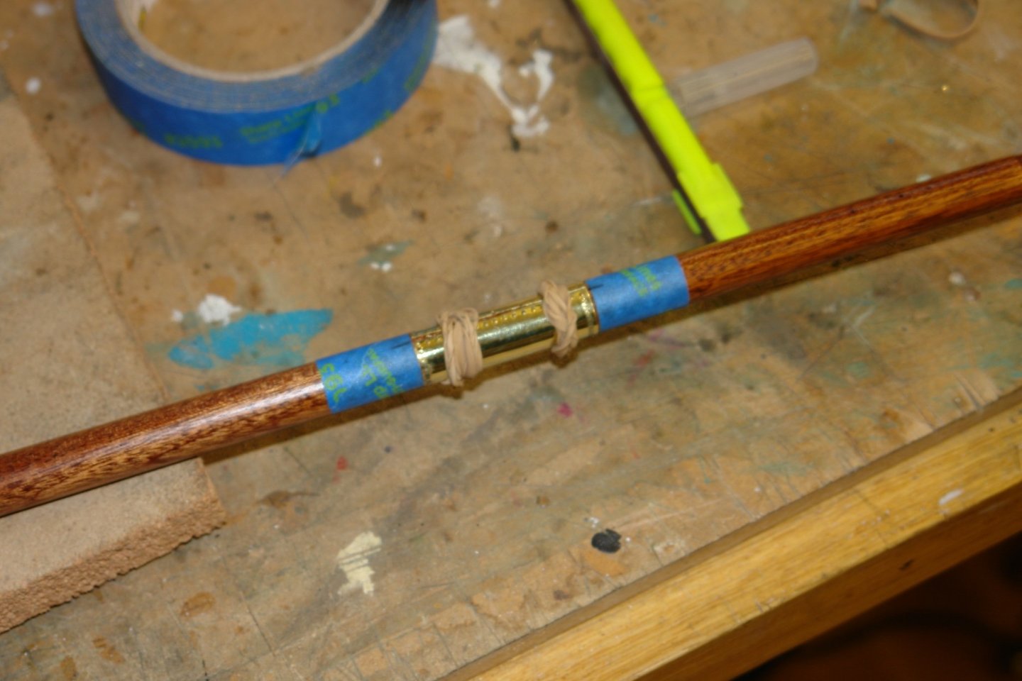
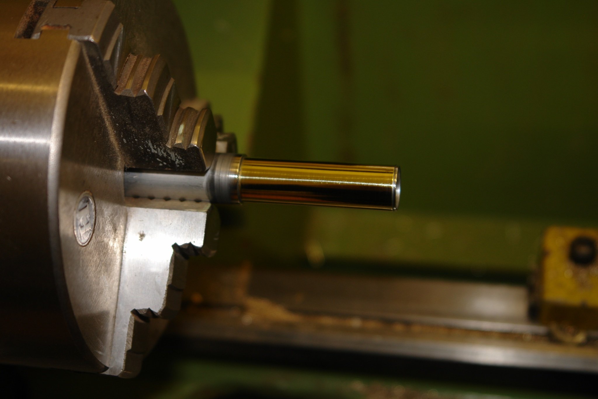
I am still working on the lower main and foremasts. Where the gaff saddle bears against the masts the masts are sheathed with brass. I made the sheaths from .004" flat brass sheet. I rolled the sheet using steel rods with the sheet supported on a cork mat. Rubbing the rod repeatedly across the sheet produced the necessary curvature.
I then machined up two pieces of aluminium tube to the same diameters as the masts. I then glued the brass sleeves to the tube using CA glue. The sleeves were held in place by elastic bands while the glue dried.
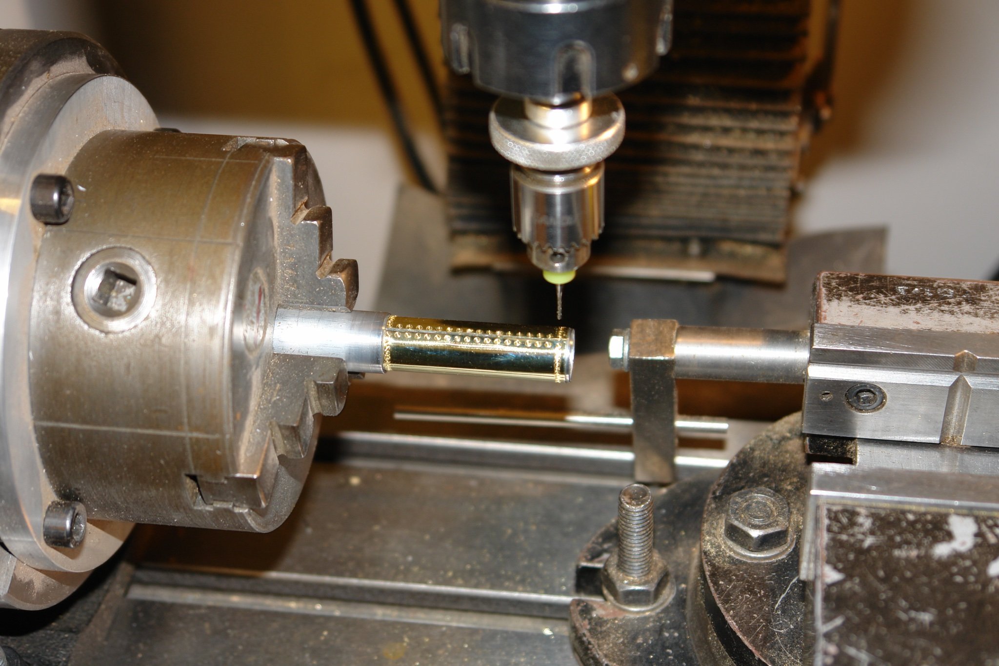
The tube was then moved to the mill and mounted in the rotary table. With this set up radial and axial indents were cut to simulate the fixing studs.

Heat was then applied to separate the sleeves from the tube.
The tubes were given a polish and attached to the masts again using CA glue and elastic bands. The positions of the sleeves were marked with tape prior to gluing.

-
On 11/29/2021 at 3:03 PM, Zbip57 said:
his true passion, which is finding ingenious ways to use his lathe and milling machines.
I agree it may look like that but the tools are only a means to the end, which is the model. Thank you for your contribution and I will take note in case my obsession deviates in that direction.
- mtaylor, Retired guy, druxey and 4 others
-
7
-
1 hour ago, allanyed said:
Allan
I find the the tension on the wire during winding makes the coils wind very tightly and evenly on the mandrel thus reducing the variability in the finished coil diameter. Its so simple to set up that it sort of makes sense to get the better control while not taking any more time. The set up time was about 15 minutes and the 20+ coils were wound in 20 seconds (lathe speed 60 RPM).
- Mark Pearse, druxey, allanyed and 6 others
-
9
-
15 hours ago, Reverend Colonel said:
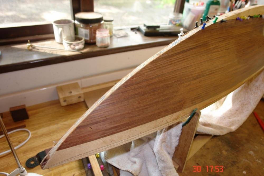
Should I bother to carve a small rabbet in the stem to receive the planks? It seems like a toss up. If I was entirely confident I know it would be the best option.
If you are not confident this is a simple alternative:-
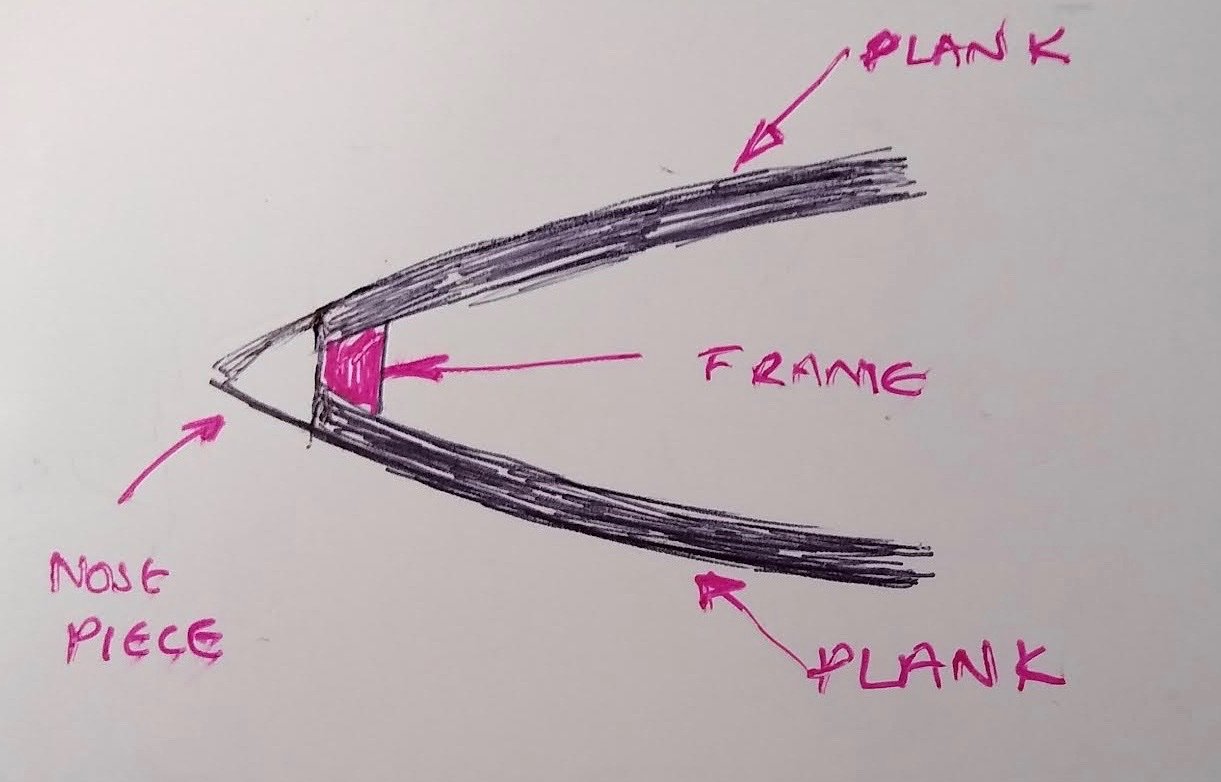
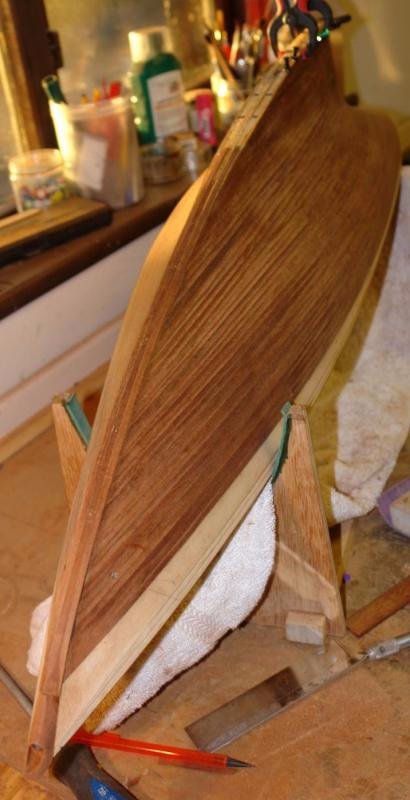
Install a vertical frame very close to the final bow position.
Plank on to this frame and then sand back the plank ends until flush with the frame.
Then glue on the nose piece. It is probably easier to glue on a square block of wood and then shape to match the angle of the planks once attached.
I quite often do a version of this technique as follows:-
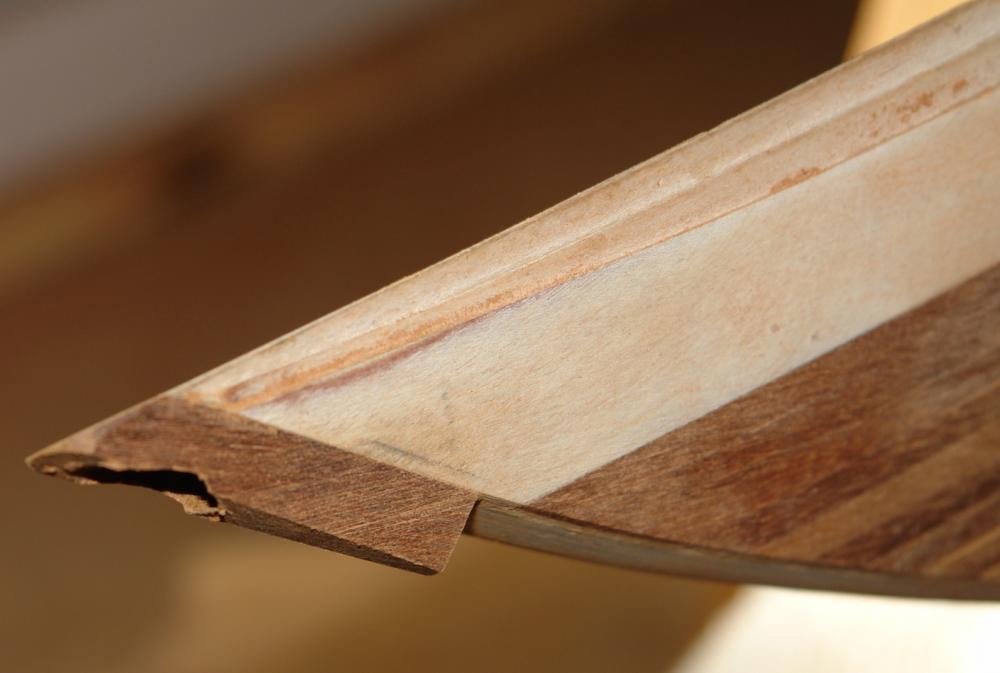
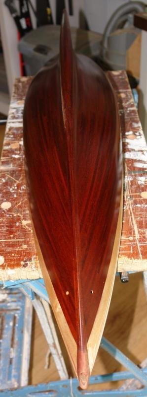
Alternatively you could laminate up the bow with the rabbit pre formed as you have done with the keel.


USS Cairo 1862 by MPB521 – FINISHED - Scale 1:48 - American Civil War Ironclad - First Scratch Build
in - Build logs for subjects built 1851 - 1900
Posted
Brian - That looks really neat but I am sure that even with a desk organiser my workbench would be back in its usual state 30 minutes later. You seem to have made a lot of progress and I particularly liked the rudder detail and smoke stacks. Beautifully crisp work.