


KeithAug
-
Posts
3,405 -
Joined
-
Last visited
Content Type
Profiles
Forums
Gallery
Events
Posts posted by KeithAug
-
-
On 1/30/2022 at 5:23 PM, OnTheSlipway said:
The davits were made from 0.5mm brass rod with both ends tapered to 0.3mm. The pairs of holes were drilled in as explained in this post. Two davits were pairwise bent into the right position and then angled inward by about 12 degrees. Small 0.3mm rings from a 0.7mm tube with 0.2mm holes were soldered to the davits (bottom left); next two small etched parts and the rest of the tubes were added. After a few hours the davits were complete.
Remarkable!!!!!!!
- mtaylor, Canute, Old Collingwood and 1 other
-
 4
4
-
Valeriy - your soldering is always very neat. You must tell me how you keep it so clean.
-
On 1/30/2022 at 9:05 AM, Wintergreen said:
Now, that I've solved this mystery it is back to the yard again. Ha!
Mysteries are the best bit. Great work.
- mtaylor and Wintergreen
-
2
-
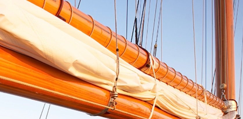
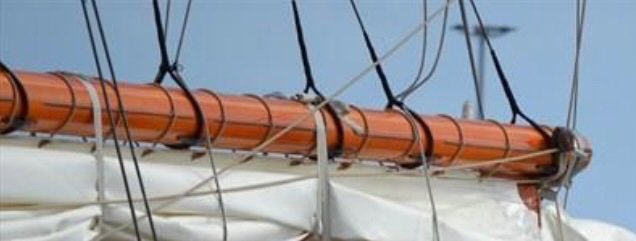
26 minutes ago, wefalck said:
Interesting, I have never come across such wear-stripes on a gaff.
Eberhard.
Yes I agree, it is a bit odd.
- FriedClams, BANYAN, Keith Black and 7 others
-
10
-
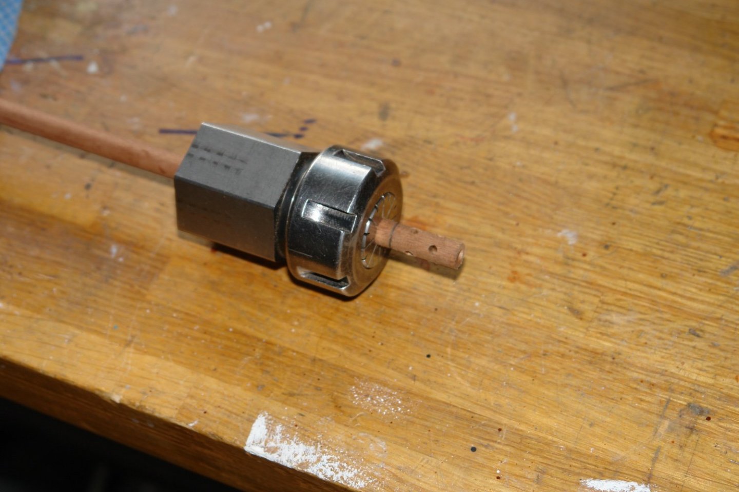
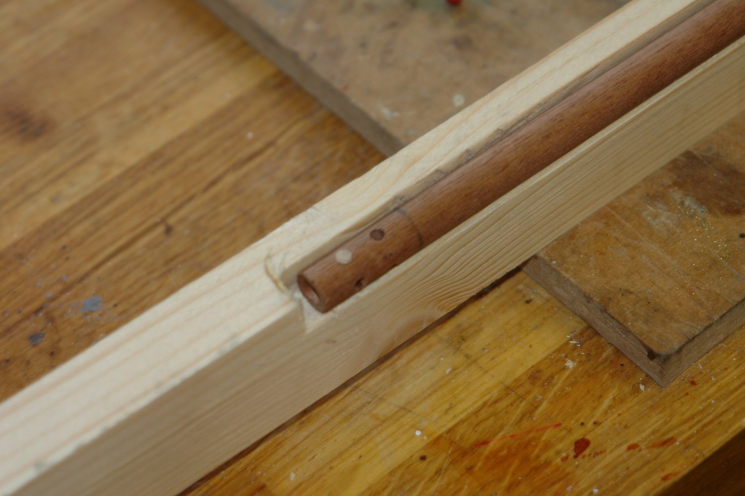
I moved on to gaffs. They were again made from mahogany dowel turned to the correct maximum diameter (the taper being left for later).
The gaffs have features which in the majority lie on 0, 120 and 240 degree radial orientations. To make rotational location easy I drilled 3 location holes on a extension to the finished boom and then used these holes for location.
I needed to cut 2 x .040" wide slots along the lengths of the gaff ad i did this on the table saw using a simple jig. A square cut out was made in a piece of scrap wood equal to the diameter of the gaff. A hole was drilled for a locating dowel. The gaff was mounted and the slot was cut with the saw fence bearing on the jig.


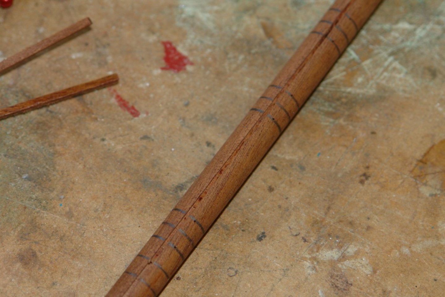
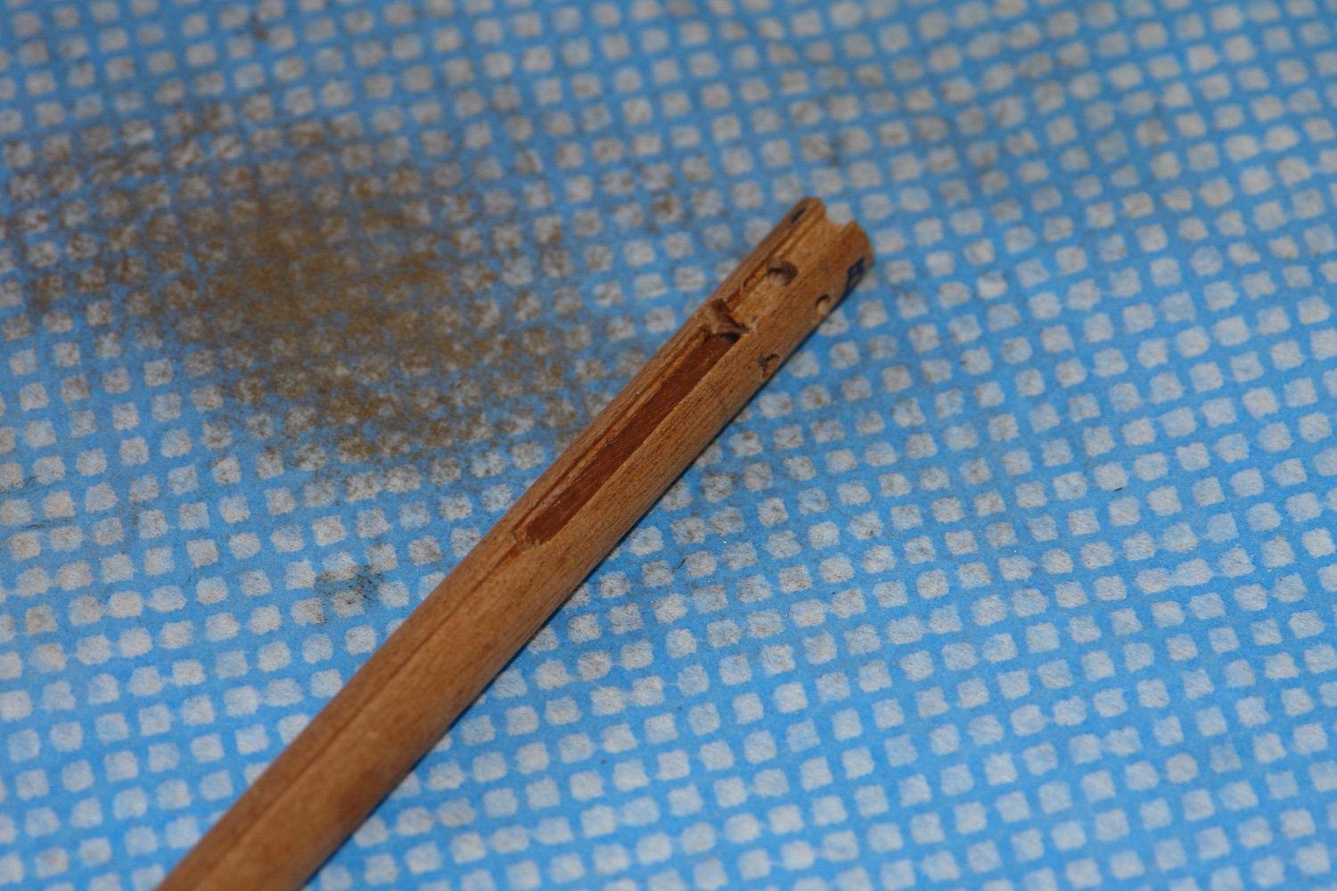
With the slots cut the ends were milled to take the gaff saddle brackets.
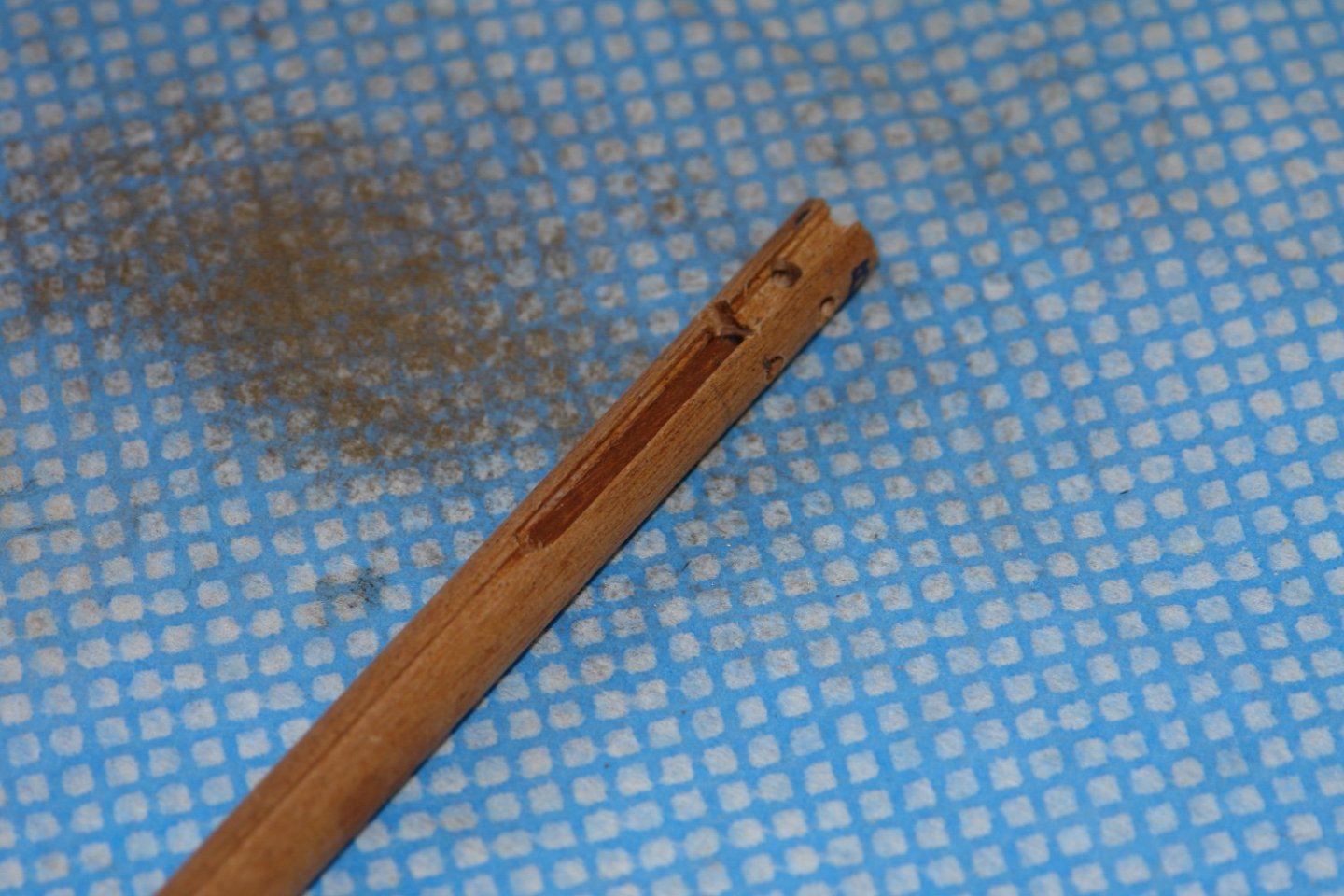
The .040" slots are for the wear strips - made form .040" brass wire.
The wear strips are not continuous so I inserted thin strips of mahogany (cut to the correct length) to segment the slots.
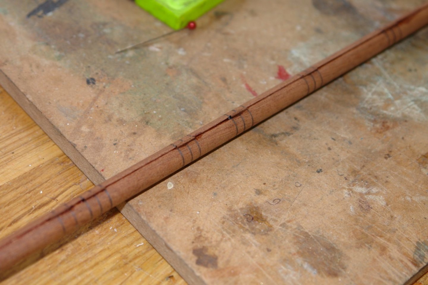
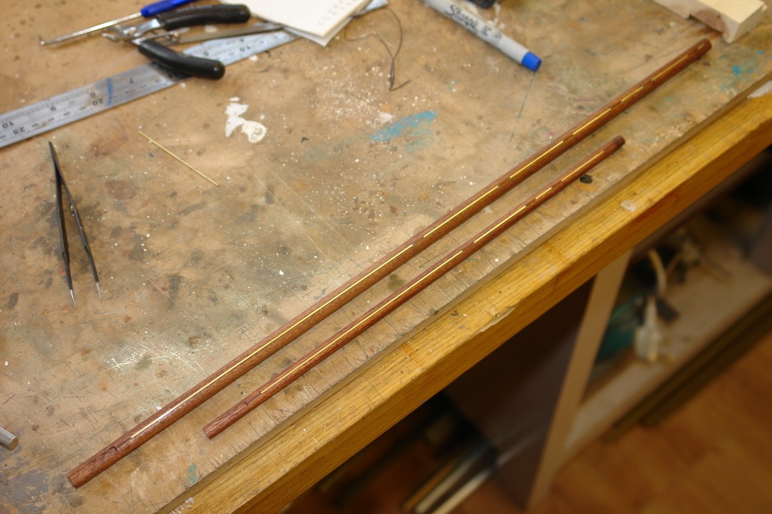
With this done I then sanded the tapers on both ends of the gaffs (the slots were deep enough not to be removed by the tapering). The brass wire wear strips were glued in with CA.
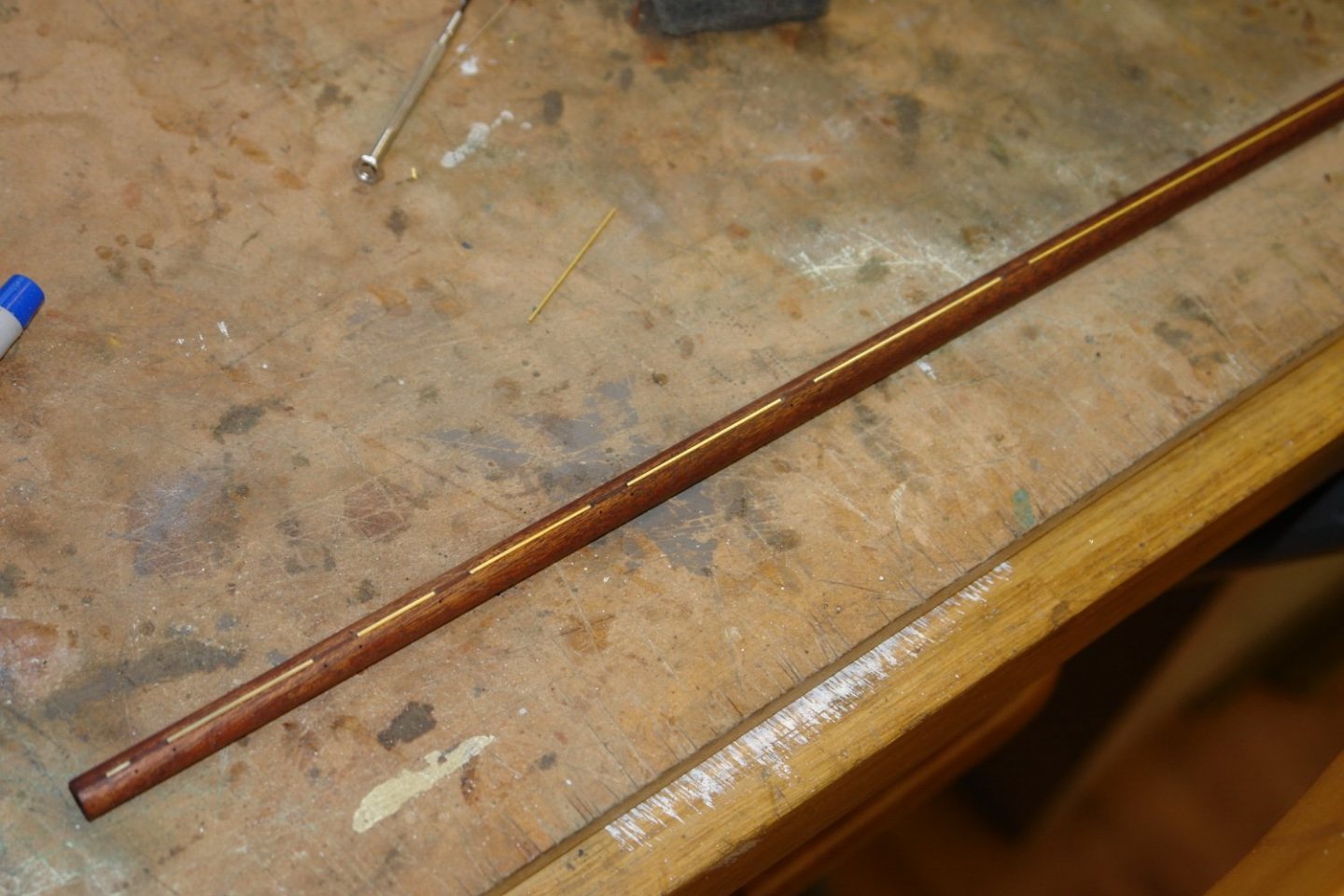
The second gaff was made in the same way.

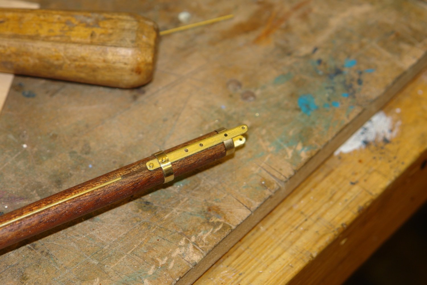
Straps for locating the gaff hoist lines are positioned at the 120 and 240 degree rotational positions. The straps were cut from brass sheet and when drilled were inserted on pins so that the end radii could be filed in one operation.
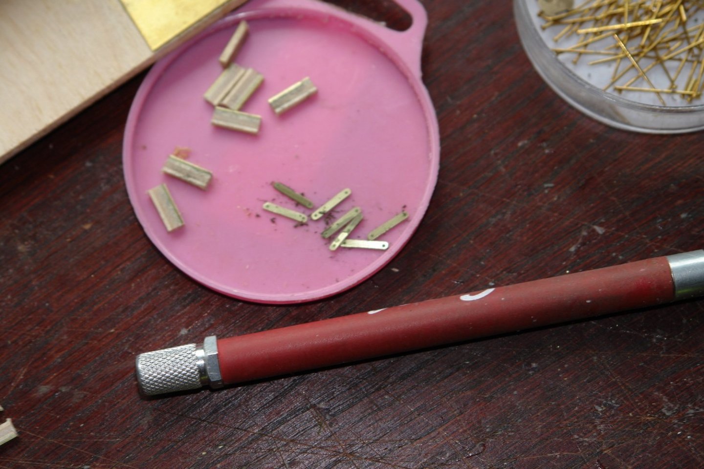
The gaffs were drilled to take the pins for the straps and the straps were mounted.
The straps for the saddle were cut and shaped to fit the previously machined slots. The hoop and the end boss was also turned and milled.
The straps were blended to the shape of the boom using a file and then the hoops were fitted.
- FlyingFish, Wintergreen, JOUFF and 16 others
-
19
-
-
Amazing detail - very impressive.
- Old Collingwood, mtaylor, Canute and 3 others
-
6
-
2 hours ago, Wintergreen said:
I cut the wide and filed down. Seems the most common approach, which also makes sense since the cutting with pliers distorts the pieces.
Hakan - Have you got a jewellers saw? Ideal for jobs of that sort and relatively cheap. If you get one invest in decent blades. The ones that come with the saws are usually poor.
- Wintergreen and mtaylor
-
2
-
Whatever happened to those beautifully elegant cargo vessels, alas their modern replacements have all the elegance of a floating brick. At least modellers can record their passing.
- Veszett Roka, mikegr, yvesvidal and 2 others
-
5
-
2 hours ago, Retired guy said:
pinging again 1 month or a year or two later, just a thought.
Hi Richard - True, but it might keep some excitement in my life.
-
Thank you Pat, Richard and MCB for your comments, and thanks to everyone for the likes.
On 1/21/2022 at 11:29 PM, BANYAN said:How on earth do you polish up these small parts to such a high quality finish, and then maintain that finish?
Pat - I think i have not been as good at polishing of late however my general process is machine finish, polish with 600 grit wet and dry, then polish with 1200 grit, then 2400 grit and then finish with Brasso liquid polish. I generally tend to accept that brass ages however if I really want to prevent this I use Renaissance, Micro-Crystalline Wax Polish. A bit expensive but excellent for maintaining the shine for years.
Update:-
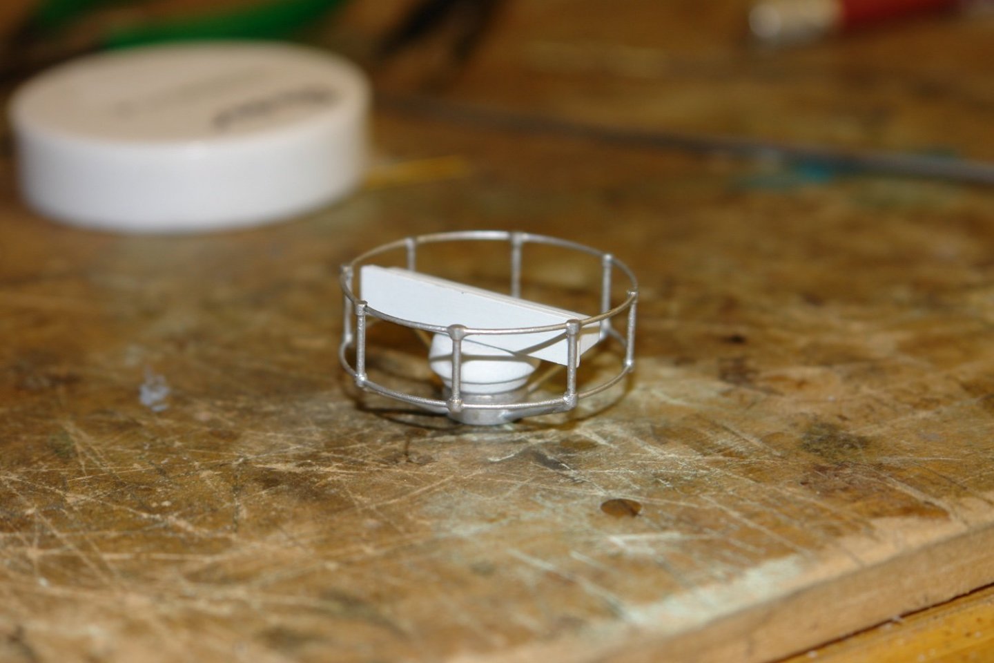
From an earlier post, Eberhard thank you - modified radar.
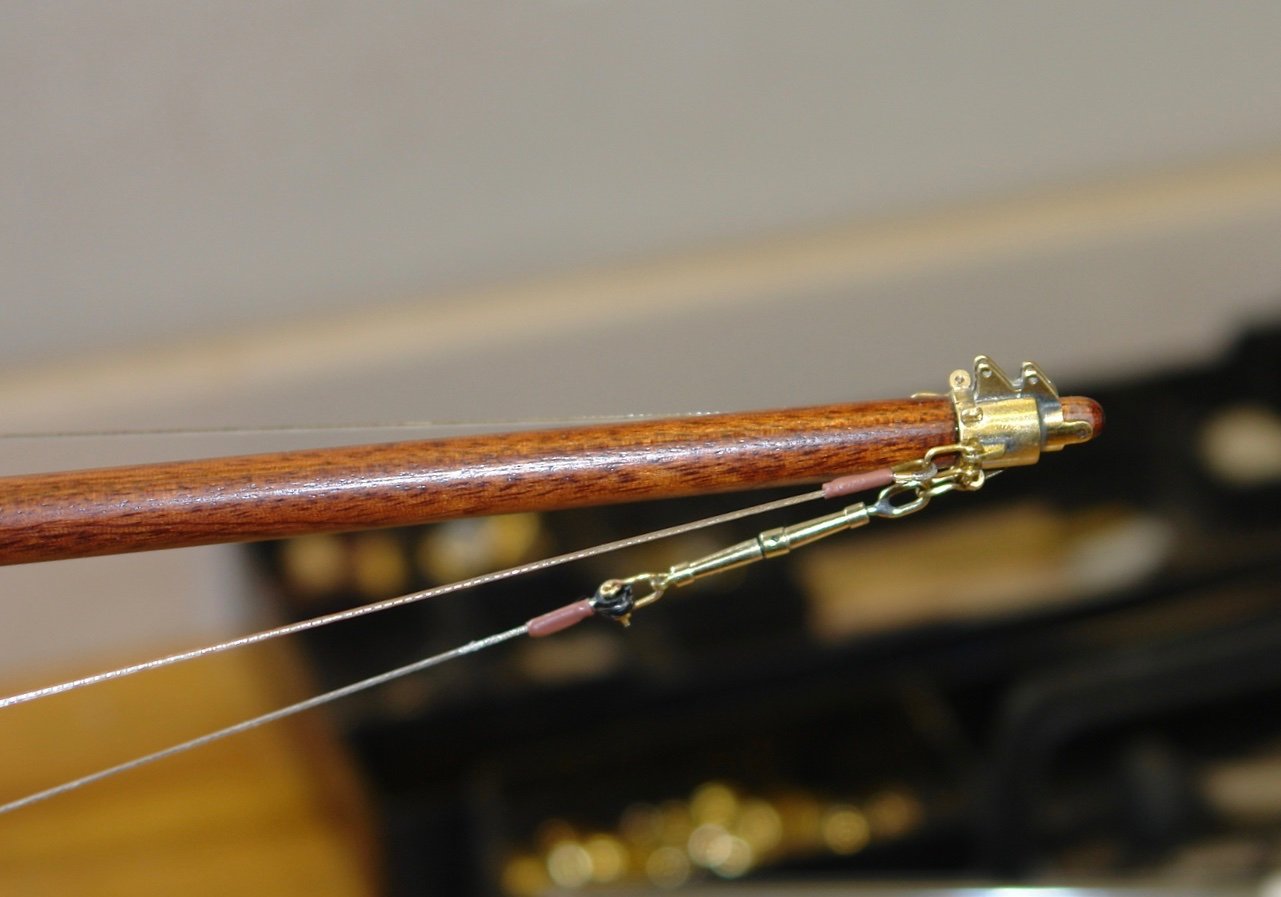
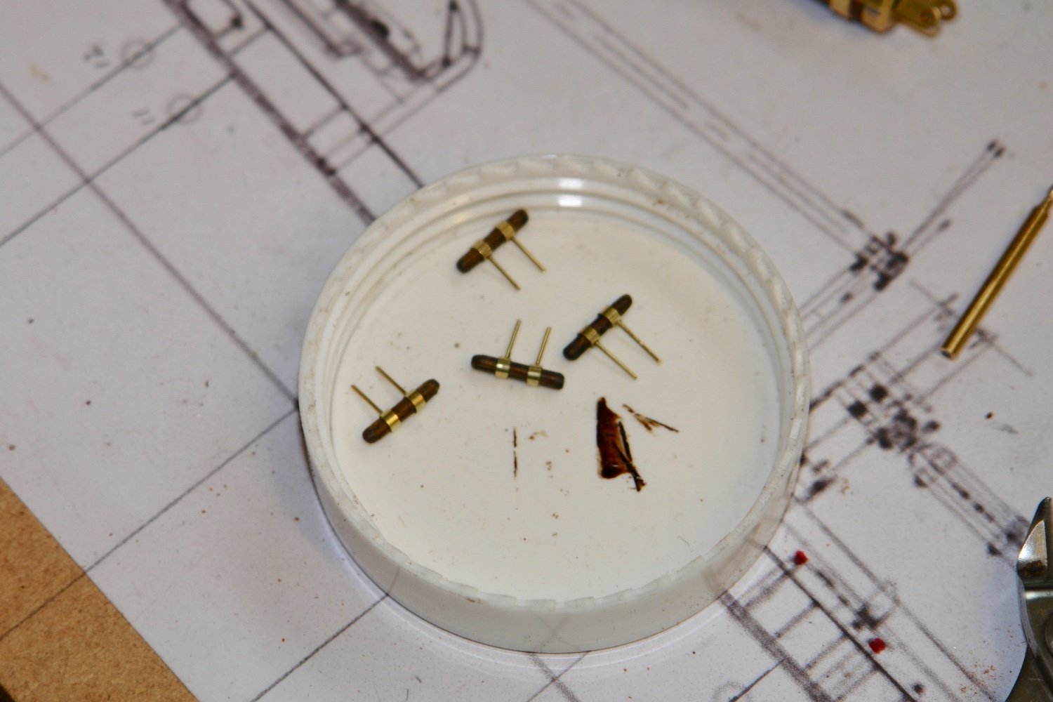
You may also recall that I doubted the strength of the shackle attachment to the turnbuckles. That is the lower end in the next photograph.
I proved they were not strong enough when rigging the bowsprit - Pinnnng!!
Although not as accurate I modified all of them as follows - old version top - new version bottom.
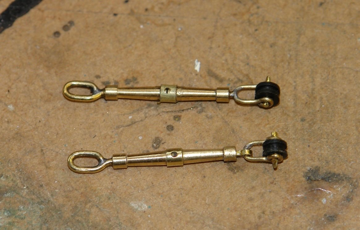
The mod involved using a vey small split pin made from .020" x .040" section brass strip.
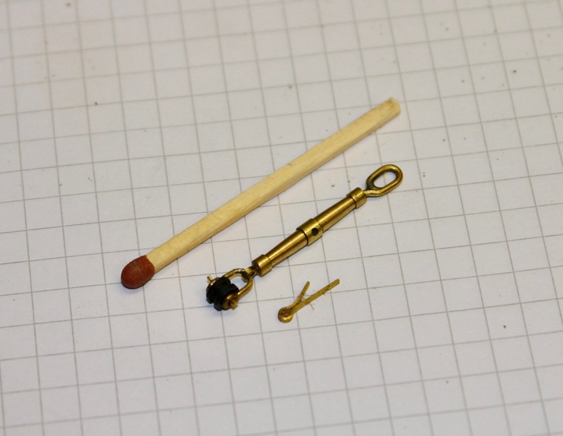
They are now much stronger and when not subject to close inspection they look fine.
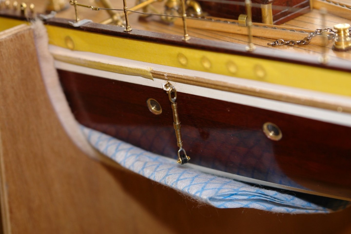
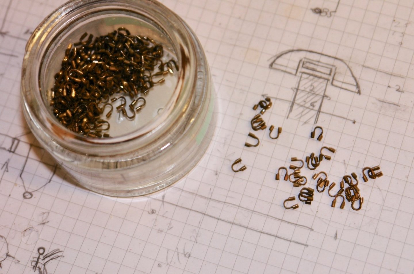
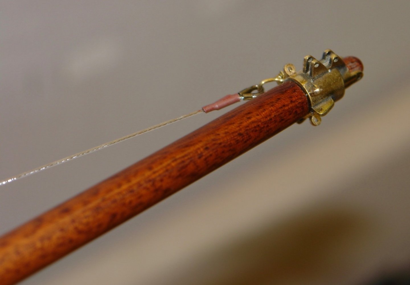
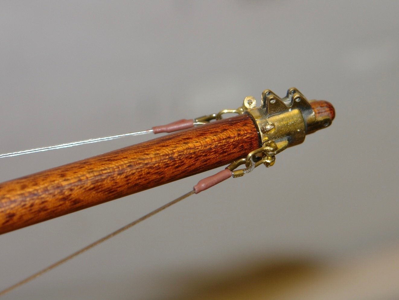
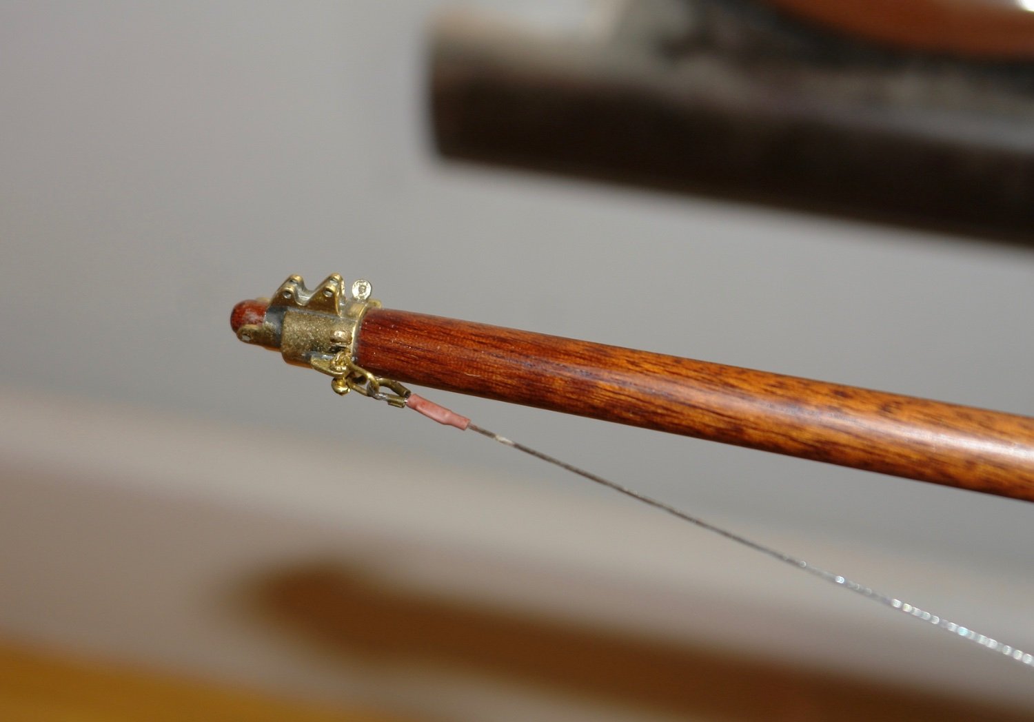
The bowsprit was rigged with .024" Beadalon clear coated multi strand steel wire. I bought wire guards to simulate thimbles and keep things neat.
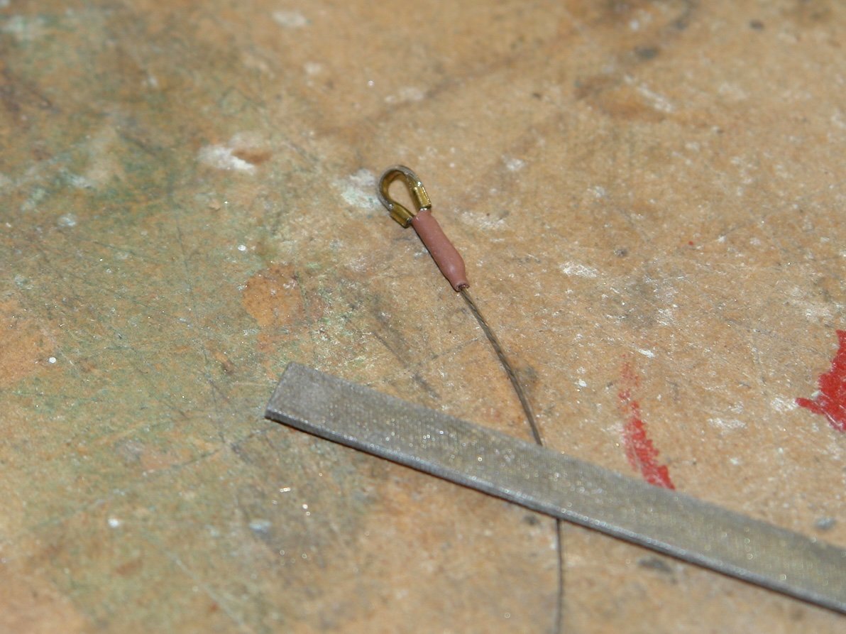
The end of the wire was stripped, threaded through a 1mm ID by 1.2mm OD tube then through the wire guard and then back through the tube. The loop was secured with a drop of CA and then heat shrink tube was used to simulate the leather protective sleeve. The "large" file in the photo is a standard needle file.
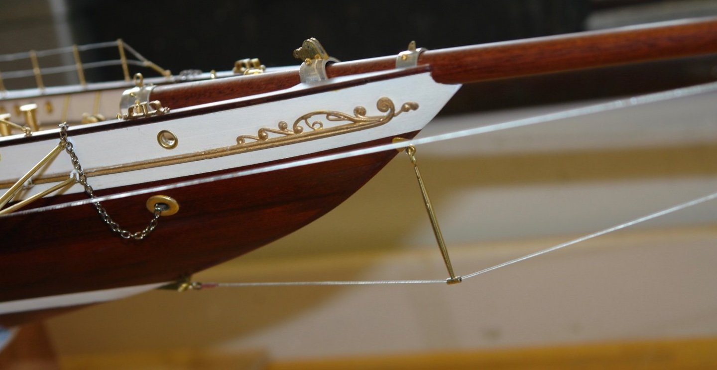
I rigged the port side bowsprit shroud very tight to correct a slight bow in the bowsprit. This worked very well.
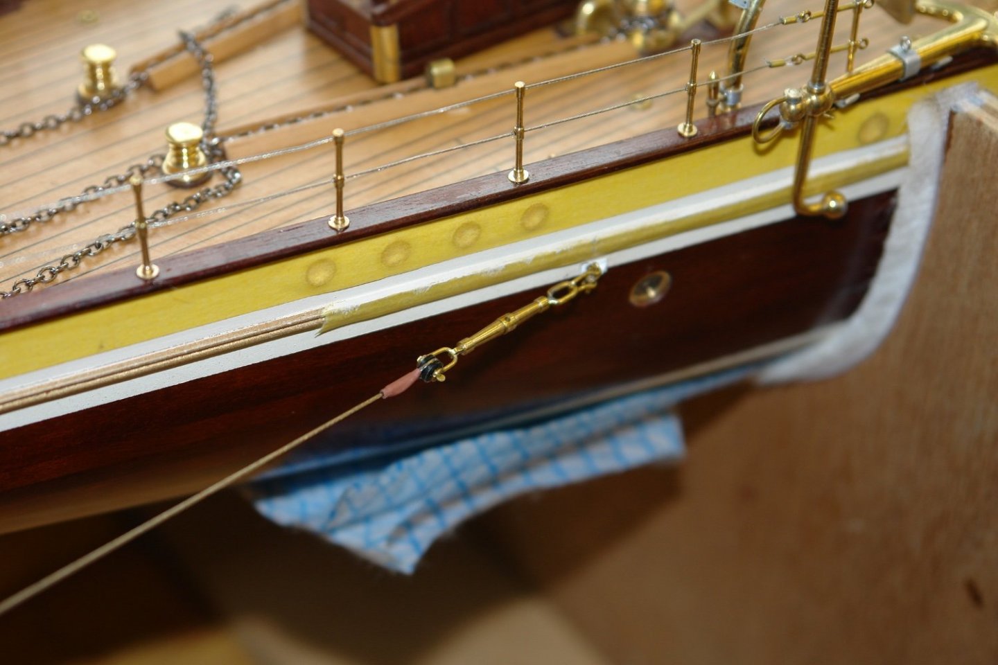
Until --------- after about an hour ----- pinnnng. The attachment to the hull was too weak and parted company. The small bracket had been soldered to a 1/16" spigot and then inserted to a hole in the hull. The solder failed. The bracket was attached to a 3/32" spigot and reinserted. Thus far this has held despite the tension in the cable.

The starboard bowsprit shroud didn't quite need as much tensioning and in consequence the hull bracket held (thus far).
The bobstay was rigged next, again with a fair degree of tension.
-
Quite a complicated bowsprit rig, very interesting. I'm not sure it is a boat for a squall?
Thank you for the block size details. I need to make many in 3 sizes
large 7mm,
medium 6mm,
small 5mm.
Looks like being a lot of fun but i will need to think about simplicity of production.
-
-
On 1/6/2022 at 8:24 PM, Glen McGuire said:
That's actually a pretty good description of my kitchen table when I'm working on one of these ships.
I am also guilty.
- Keith Black, mtaylor and Glen McGuire
-
3
-
-
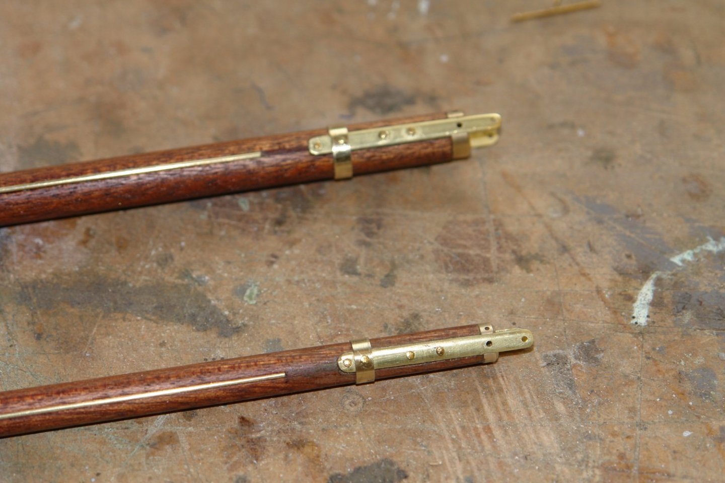
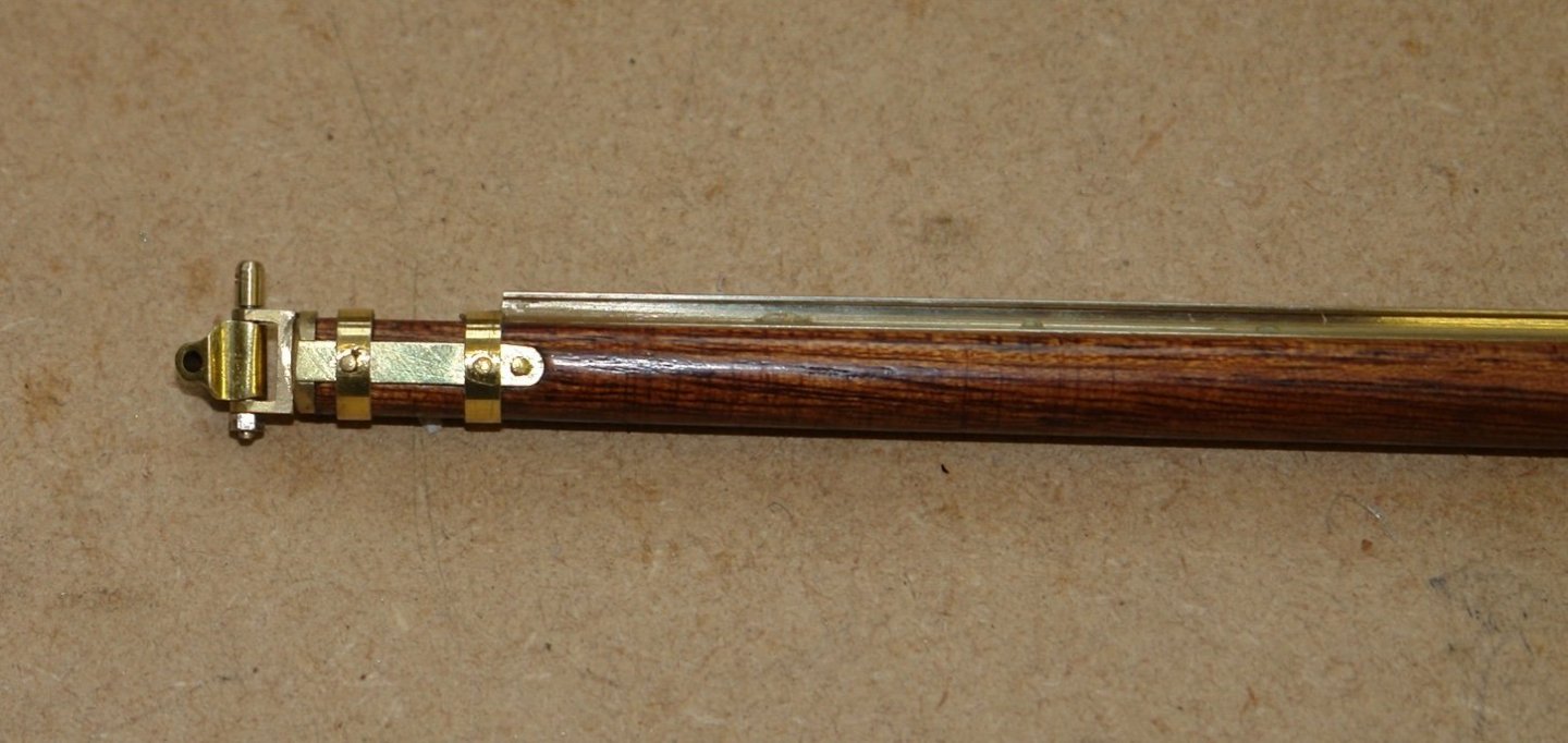
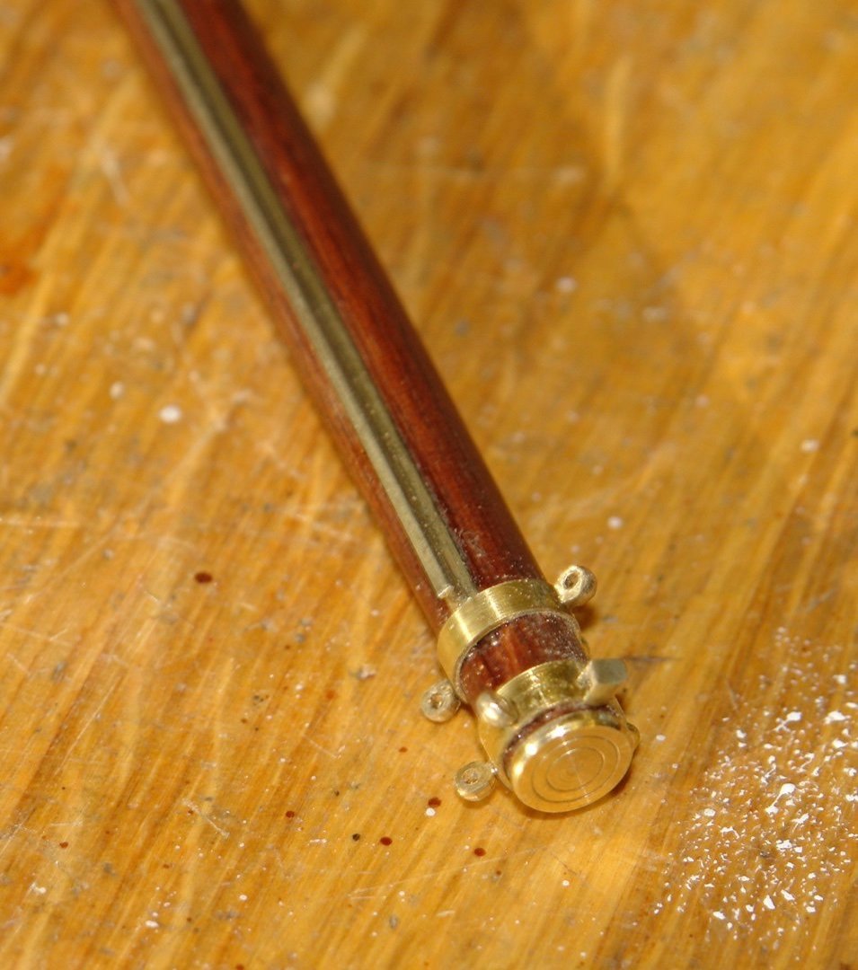
I'm still working on the main and foremast booms.
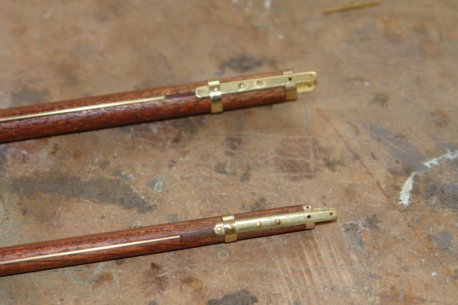
The sheave for the reefing line was fitted. The boom was slotted on the mill, a small sheave was inserted and then the wooden closing piece was glued in place. The closing piece is a lighter coloured wood on the original and this was reproduced on the model. The end boss was turned and glued in place.
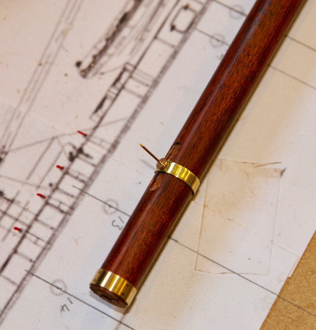
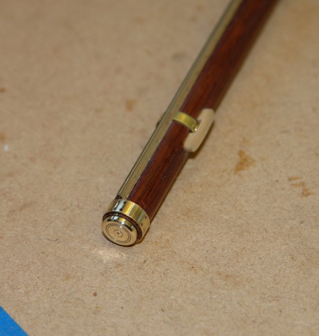
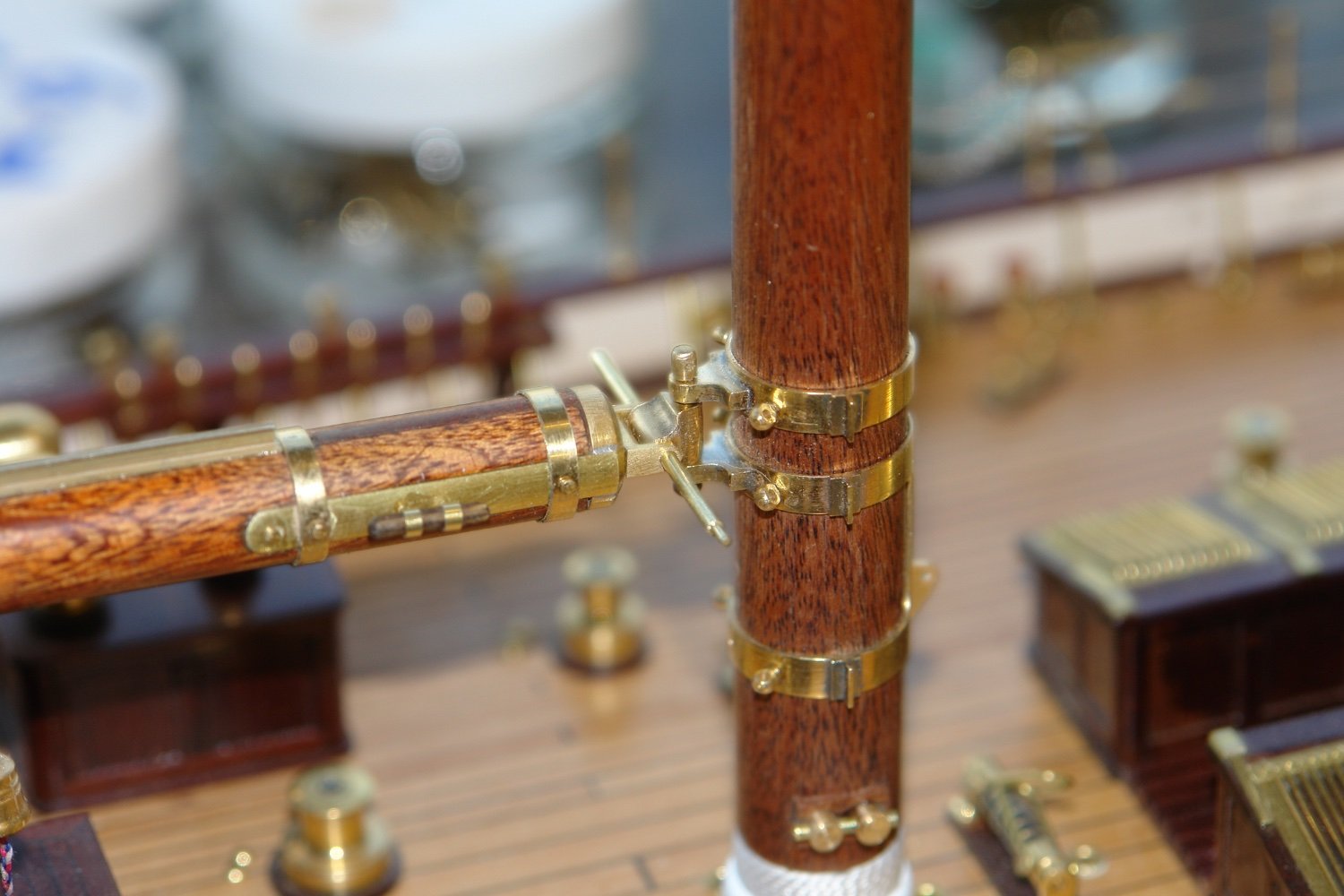
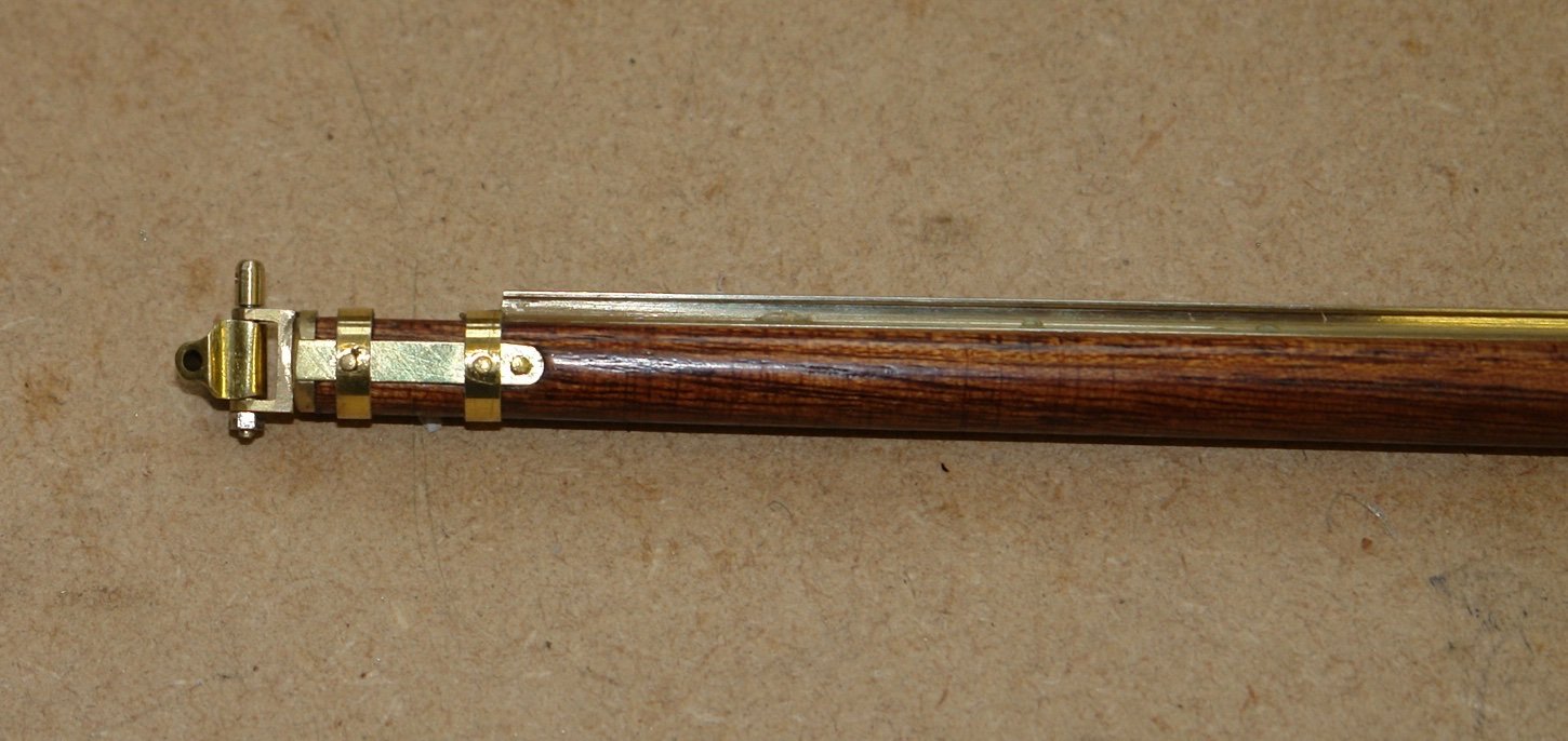
The cleats at the fore ends of the booms were made. These were made from wood and brass as per the original.

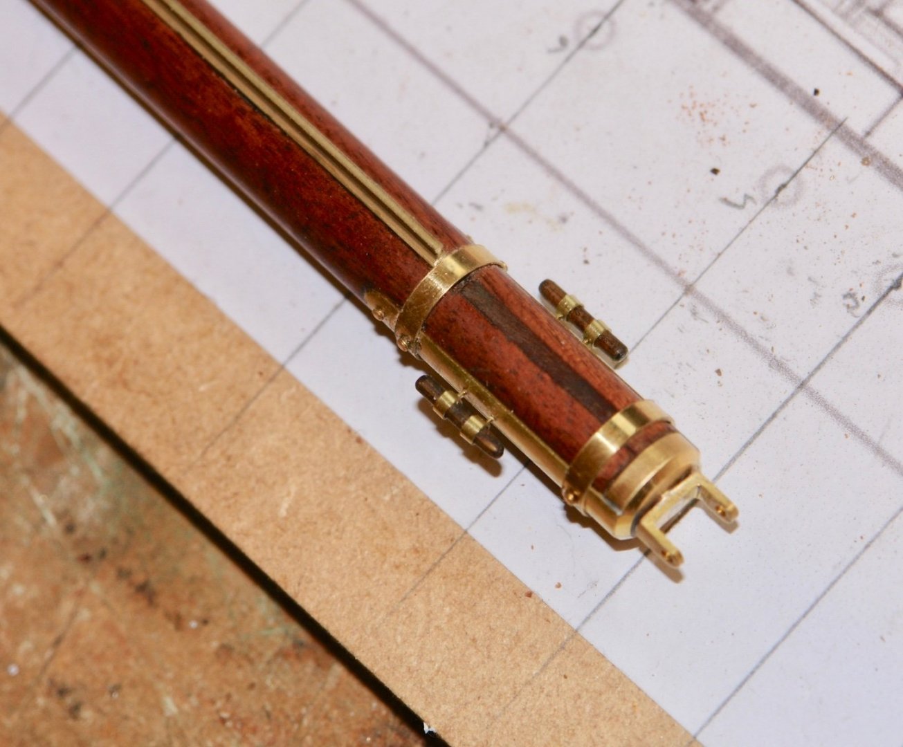
The vertical hinge pin was made with an upstand drilled for the attachment of the sail. The horizontal pin is obviously a temporary arrangement.
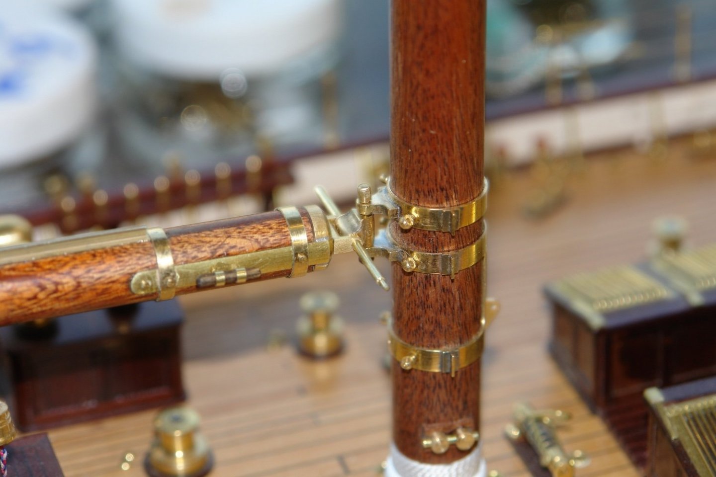
The fore mast boom followed a similar process.
-
On 1/20/2022 at 8:34 AM, Retired guy said:
Absolutely brilliant Keith
Thank you Richard - I see your Bluenose log has been quiet for a while. I trust all is well with you?
- mtaylor, WalrusGuy, Retired guy and 2 others
-
5
-
Nice bit of carving and shaping, everything seems to be going well.
-
I must admit I hadn't realised how big the vessel is. Lots of opportunity for detail.
-
3 hours ago, wefalck said:
Good to see that the crew will not slip under the table
One has to get the priorities right.
1 hour ago, Valeriy V said:is the rudder blade on a real yacht made of wood or metal
Valeriy, Germania has a steel hull and rudder. the original Germania was built for the German steel and armaments magnate Krupp. Early on in my build log a lot of discussion took place on whether to paint the entire hull or leave the wood finish. In the end I couldn't live with painting over the mahogany and compromised on the wood finish.
-
A bit of sorting out loose ends before getting back to the masts and spars.
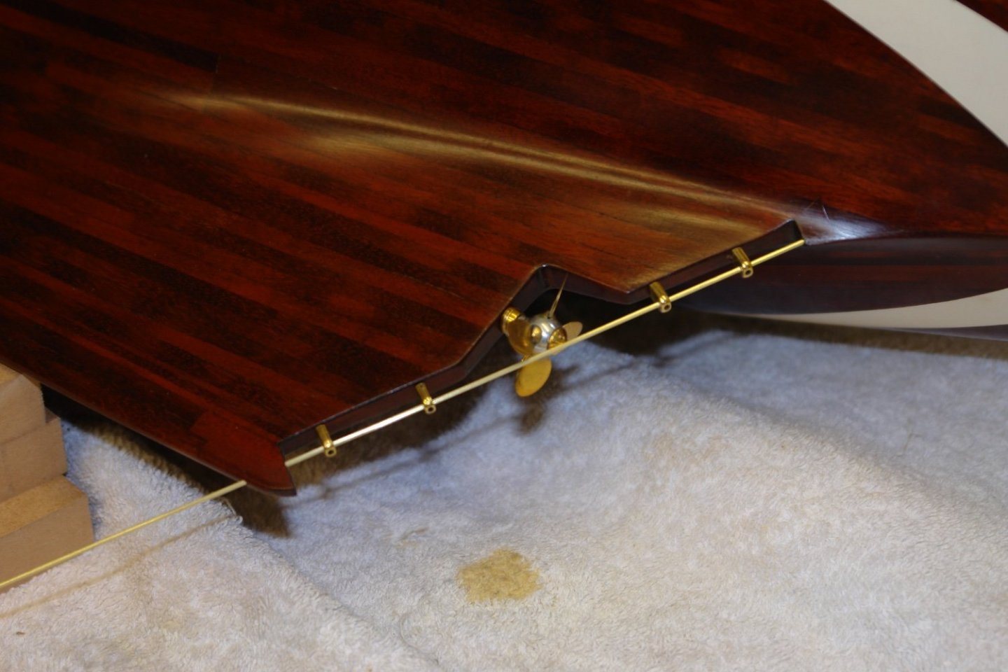
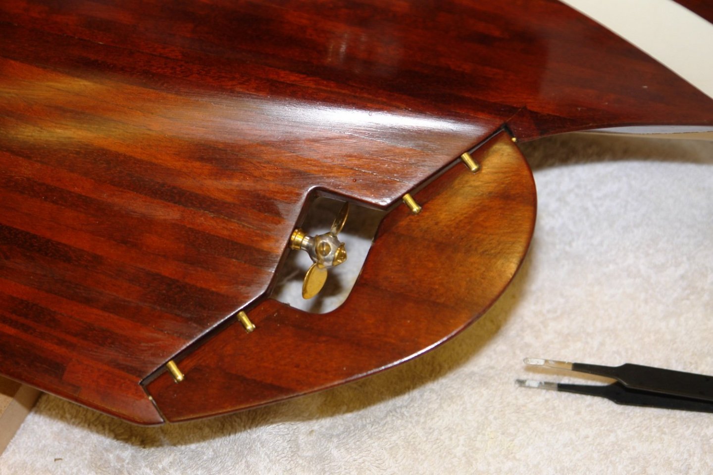
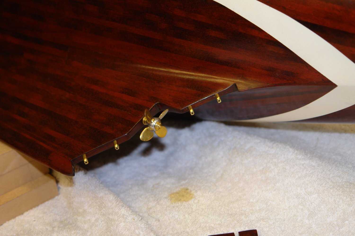
The screw and the rudder have been sat in my bits box for over 2 years and now seemed to be an appropriate time to fit them.
The bore for the screw had been pre drilled and it was a simple case of insertion and gluing in place. Holes for the hinge mounting spigots had also been predrilled and these were inserted and glued in position.

The rudder shaft was a piece of 1/16" brass rod. Fortunately, by either luck or judgement, it slid into place without interfering with the screw. As can be seen the shaft locates in the 4 hinges and a hole in the hull and keel. Satisfyingly the alignment was spot on.
To mount the rudder the shaft needed to be in 2 pieces ( a gap being required at the screw cut out).
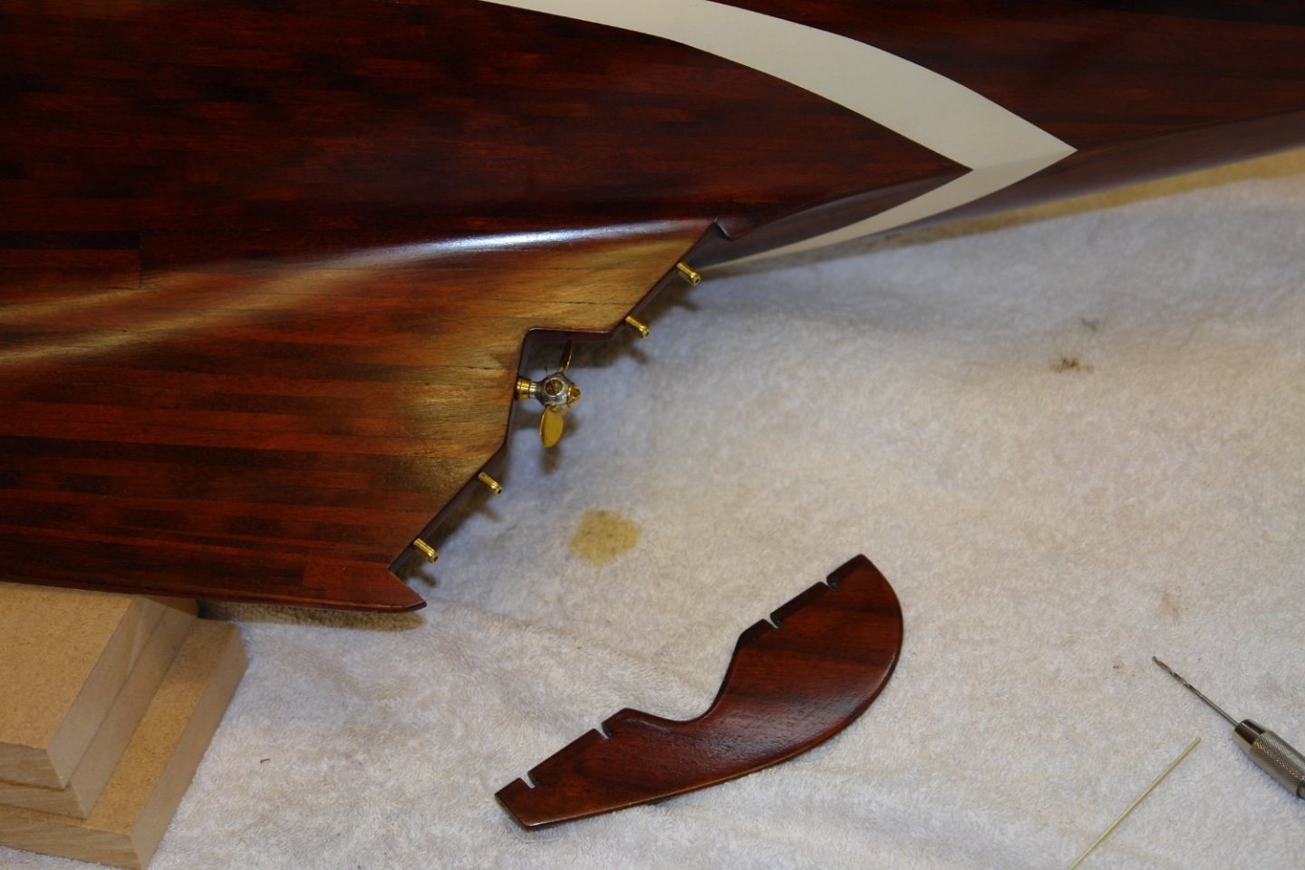
The upper shaft had to be inserted through the lower part of the rudder.
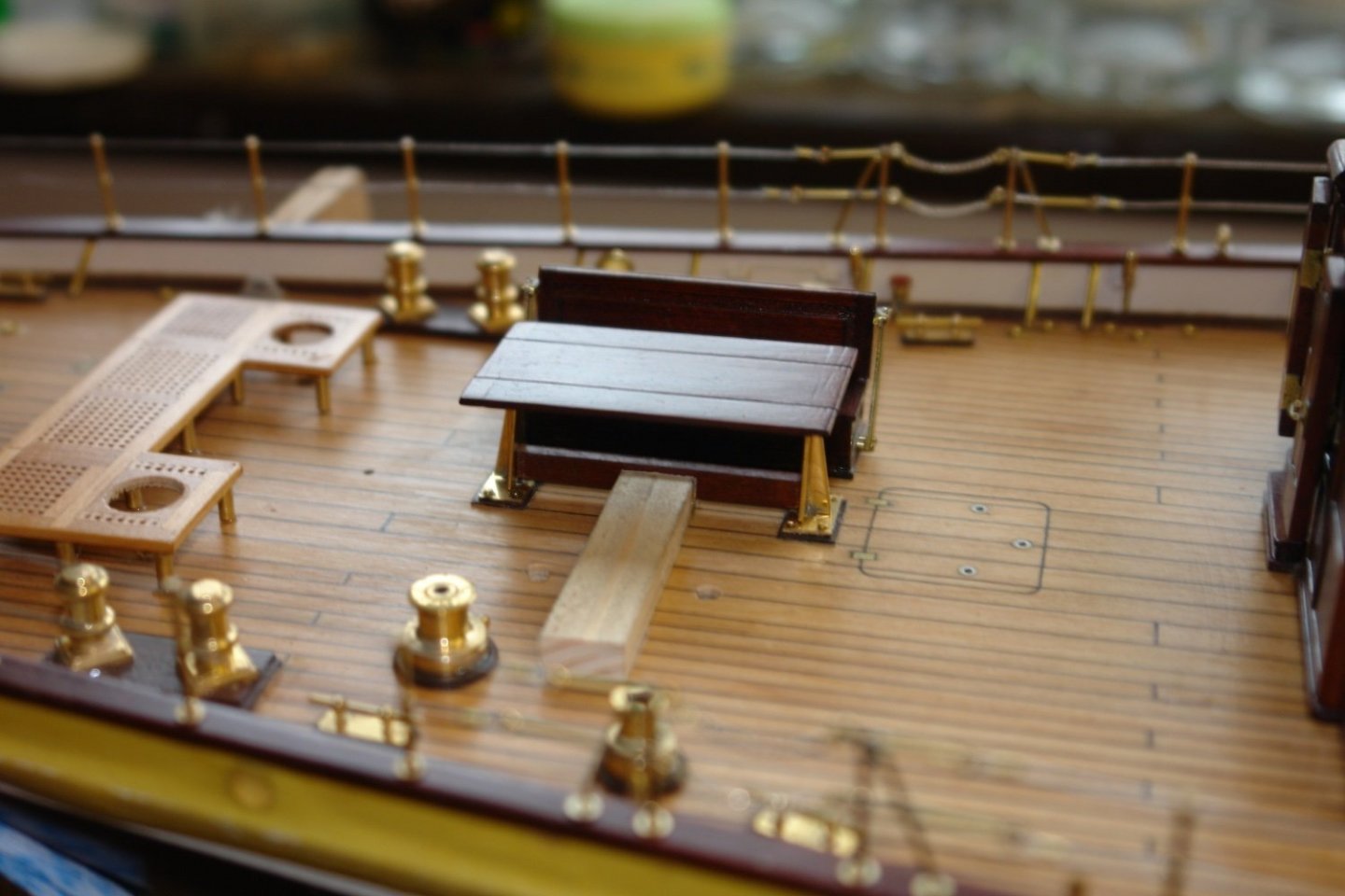
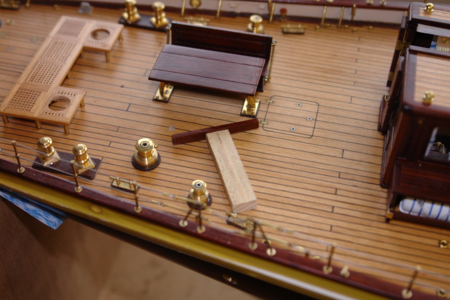
Some time back one of you pointed out that I had omitted the cross brace below the on deck dining table. Quite a serious omission as its main use is to brace the crew who are sitting and drinking gin while close hauled. I had looked at retrofitting it some time ago but getting it located and glued in place had proved somewhat fiddly, so I left it for later. Today was "later".
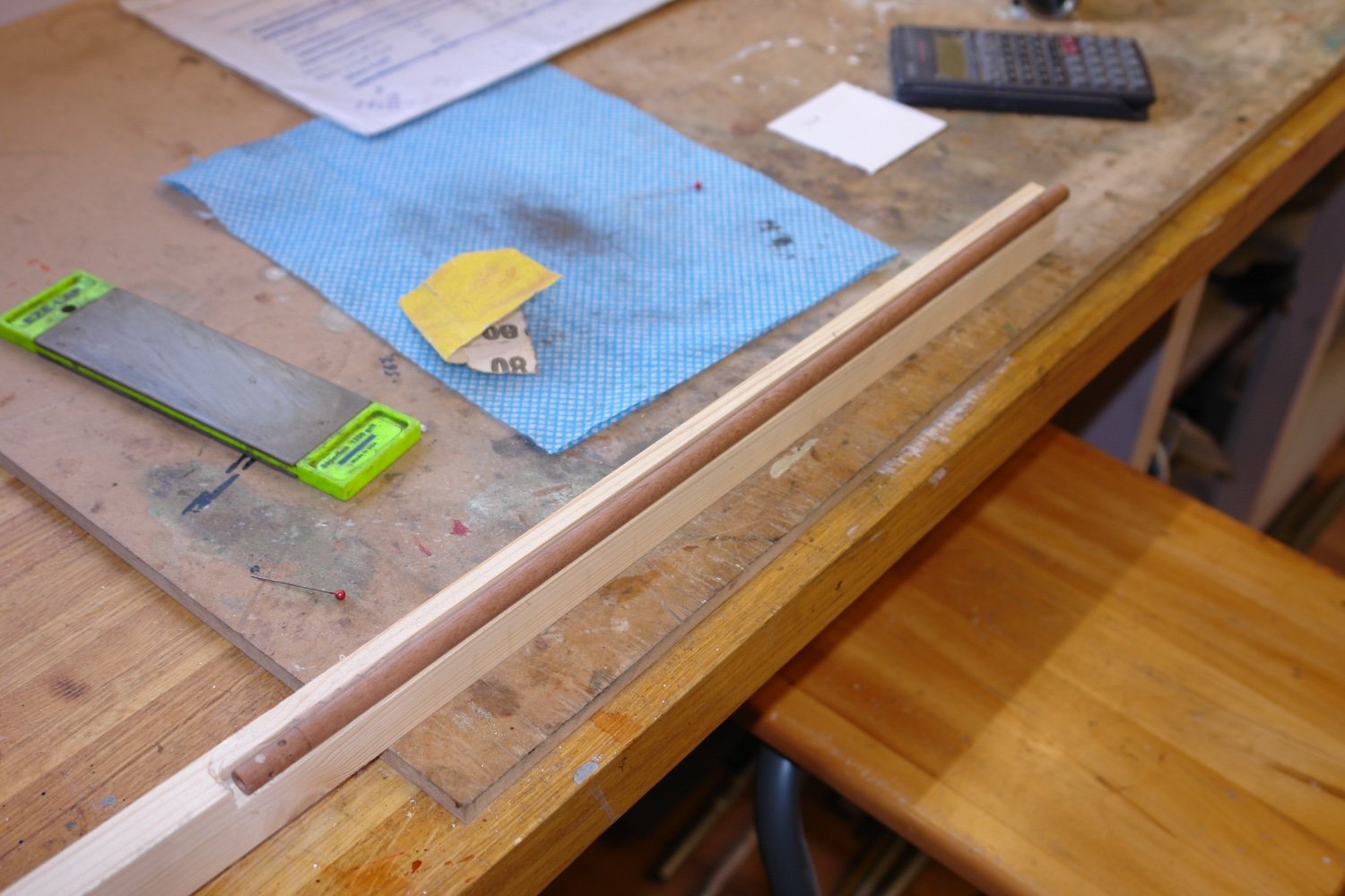
After some head scratching i decided to fix the brace to the end of a piece of scrap wood with double sided tape. The correct height been set with a couple of shims.

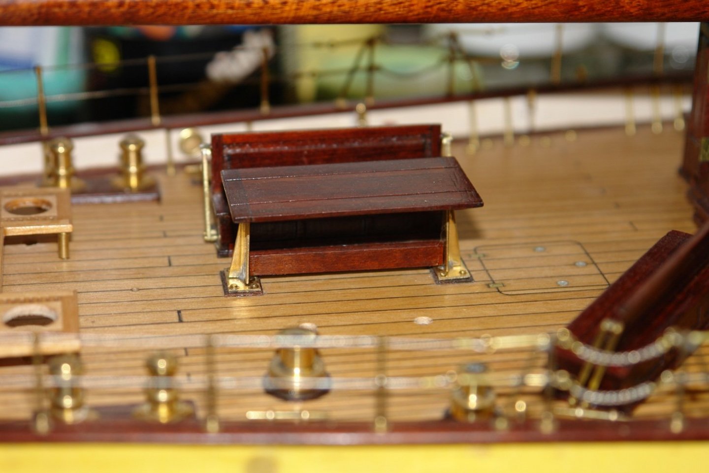
With this set up the brace was moved into position and glued with CA.
Once the glue was dry the scrap wood was eased away breaking the double sided tape bond. The crew can now drink their gin in comfort in the knowledge that they are no longer rudderless.
-
-
On 1/17/2022 at 5:37 AM, michael mott said:
I am assuming it is Mahogany
Yes Micheal. I am still working my ay through a 1930's mahogany dining table, picked up for a song at the local auctioneers. "Brown" furniture is really out of fashion here and much of it ends up in the skip. Cutting up a quality table seems a crime but at least I rescued it from oblivion. Old mahogany is vastly better than the modern stuff.
Thank you to everyone for your continuing support and comments.
- FriedClams, Keith Black, wefalck and 4 others
-
7
-


ADA CLIFF 1918 by Jond - 1:48 - three-masted Boothbay Schooner
in - Build logs for subjects built 1901 - Present Day
Posted
Jon - I always struggle with making the sails look full. In the end I convince myself that its the end of a perfect day, the wind has failed and the crew have decided to partake in a round of gin and tonics before taking the sales down. This makes the set of the sails perfect.