


Roger Pellett
-
Posts
4,519 -
Joined
-
Last visited
Content Type
Profiles
Forums
Gallery
Events
Posts posted by Roger Pellett
-
-
My experience is that sharp corners and fiberglass don't get along well. The glass fiber wants to float on the resin precluding sharp corners. It might be easier to cast the sonar dome in place once you have glassed the hull.
Roger
- mtaylor and Old Collingwood
-
 2
2
-
I don't know if this would work with your kit model but I built the bow platform and the stern sheet platform for a longboat that I am building by first fitting a piece of very thin model builders plywood That is available as thin as 1/64 in (approximately 1/2 mm). I then glued the boxwood planking to the plywood.
Roger
-
Daniel,
I don't know whether your query is to support construction of a model or for some different purpose, but another source that discusses brace winches and rhe ships that carried them is Allan Villers' The Way of a Ship. There is a good isometric sketch of a brace winch in this book by Harold Underhill. Villers' perspective is that of a practical sailor who actually used this gear.
Roger
-
John Harland's book Capstans and Windlasses available used from Amazon for $9.98 includes a chapter on brace winches and the Jarvis winch in particular. Illustrations are not great, not as good as Nils posted above, but there is useful written descriptive material that would appear to be the kind of stuff that you're looking for.
Roger
- Mirabell61 and mtaylor
-
2
-
-
How does a crew member reach the forecastle from the main deck?
Roger
- mtaylor and CaptainSteve
-
2
-
The view that you shown includes water lines drawn parallel to the keel, station lines perpendicular to the keel and buttocks. Assuming that you have at least one more view (a plan view or a body plan) you have sufficient information to reconstruct a lines plan.
Start by preparing a table of offsets- x,y,z coordinates measured from the centerline for water lines and base lines for buttocks. Then plot them and pass curves through them. Whether by hand as I prefer to do or by CAD the process is the same. Your body plan (frame shapes) may be plotted from your other two views. Your curves may not pass exactly through all points and here is where some judgement on your part is required to produce "fair" curves with intersections that match exactly in all views.
Keep in mind that a definitive lines drawing that exactly portrays the shape of a known vessel is an illusion. Five naval architects making five lines drawings from the same table of offsets will produce five slightly different drawings because of the fairing process described above. The important thing is to make a drawing that accurately portrays the vessel's characteristics.
Roger
- thibaultron, trippwj, jud and 4 others
-
7
-
Would an air eraser be too aggressive?
Roger
- mtaylor and thibaultron
-
2
-
I have rebuilt four wood canvas canoes. Two Old Towns, a Shell Lake, made in She'll Lake, WI, and one made buy Native Americans near Quebec. All involved replacing broken ribs, planking, and re-covering. I used canvas not fiberglass for this. The worst part of the job is stripping off the old finish and sanding and re-varnishing the inside. The best in show model for NRG's recent contest was one of a wood canvas canoe. See the cover of last spring's journal
Roger
- mtaylor, Old Collingwood and Mike Y
-
3
-
Over the past 25 years I have used several gallons of West System epoxy repairing boats for our community sailing association, restoring wood canvas canoes, and building a glued lap strake canoe. I have found the product to be easy to work with and 100% reliable.
For glassing your hull you will probably want the longer pot life that you get from the slow cure version, but the resins are interchangeable so if you later have an application for a faster cure all that you have to do is buy the fast cure hardener.
Be sure to buy a pair of the correct West System mini pumps. These allow you to dispense resin and hardener in the correct ratio. Mixing resin and catalyst in the correct ratio ensures success.Despite commonly held belief, more hardener is not better! It just means that you will end up with a gooey mess.
One criticism of West System is the amine blush that forms on the surface of their cured resin. This can interfere with curing of subsequent coatings. For a small application like yours this will not present a problem as a light sanding will remove it. Something that you will probably want to do anyhow.
Roger
- mtaylor and Old Collingwood
-
2
-
The line in question is called a vang. It's purpose is to prevent the gaff from sagging to leeward causing the sail to twist, an inefficient shape. Vangs were rigged in pairs. The windward one would be set up to control the gaff and the leeward one slacked off. When the sail was not set, by setting up both vangs the gaff could be left "standing," not lowered. The sail could be then brailed up to the gaff and mast.
Yes, you need to rig two gangs, port and starboard.
Roger Pellett
-
-
-
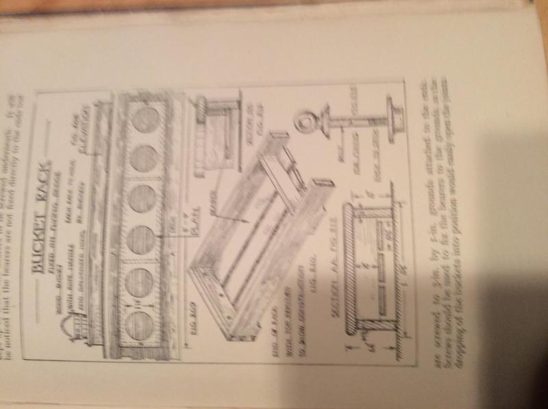
Mike,
If you choose to add fire buckets, this rack from Ship Joinery by Duckworth (1924) would be typical and appropriate.
Roger
- Red, Mike Dowling, WackoWolf and 5 others
-
8
-
In my opinion the best single reference on British ships boats is The Boats of Men of War by W.E. May. This book includes several drawings and several other illustrations of longboats. Of particular interest is the boat illustrated on page 90. Although this probably dates from the first half of the 1700's it is the original drawing that I know of that includes a sail plan and details of rigging which incidentally vary considerably from the rigged longboat model in the NMM. Howard Chapelle chose this boat as an example of a longboat in his American Small Sailing Craft. His drawing of this boat based on the Admiralty drawing reproduced in May would be available from the Smithsonian.
Roger Pellett
-
Steve,
Nice model! Your engine room needs a couple of huge 3 to 4 feet long open end wrenches and perhaps a pry bar 5 ft long. The whaleback steamship SS Meteor with a 2000 ihp triple expansion engine has some as long as 6 ft. These engines had a tendency to lock up with a piston on "dead center.and these tools were needed to roll the engine past this position. Some engines had a flywheel with a number of holes around its periphery. A pry bar could be stuck in these holes. Meteor has a heavy disc pierced with holes on its Stephenson reversing gear. Hanging nearby is a huge spanner wrench that fits the holes in this disc. This allows the slide valves to be manipulated to accomplish the same purpose.
Roger Pellett
-
Bob, if you need a good reference for steam launches with lots of pictures and some hull lines, pick up a copy of "The Steam Launch" by Richard Mitchel. Used copies are available for less than $20. This book also includes pictures of boilers and engines.
Roger Pellett
- FriedClams, Elijah, ggrieco and 4 others
-
7
-
-
Michael, sorry to hear about your leg injury. I hope that you are back on your feet soon. I tried to email you relaxation,not pages of McCaffery's book on spinning wire rope but I got a non-delivery notice. I'll try again.
Long story short he chucks necessary number of strands in his Unimat, loops the free end through a bar that he holds tight, pulls the whole thing tight and turns on the lathe.
Roger Pellett
-
Michael, the Lloyd McCaffery book is Ships in Miniature. He discusses his simple method for producing nichrome wire rope on pages 51 and 52. If you don't want to buy a copy of this book for yourself send me a PM and I'll send you the relevant pages.
Roger Pellett
-
-
Michael,
What an interesting project! The lifeboats alone are wonderful models, not the crude poorly shaped objects often seen, and the Welin davits too.
Regarding miniature wire rope, you might want to check out fishing tackle, specifically cable used to hang downrigger weights. This is seven strand stainless steel so it is real wire rope. I'm not sure how small it comes. One spool that I found on the web listed the diameter as .032in which is a bit large for your purposes but maybe you can find a smaller size.
The miniature model maker Lloyd McCaffery writes of spinning rope for his models from nichrome wire. 36ga nichrome wire is available from Amazon.
Roger Pellett
-
On a visit to the Royal Navy Museum, Portsmouth a month ago I went past HMS Victory on my way to the new Mary Rose museum. The inside of the gun port lids are now painted a rather startling orange color. Looks like the keepers of the ship would come down on the red ochre side of the debate.
Roger Pellett
- Canute, Chuck Seiler and mtaylor
-
3
-
It depends how your chuck is mounted. On many drill presses including the one that that I have, rhe Jacobs chuck is mounted on a morse tapered shaft. There is a threaded nut above the chuck that can be used to push the chuck off. This setup is not designed to accept side loads and loads from routing or milling can cause the chuck to wobble and in some cases to fall off- personal experience!
If your drill press works this way you will have to see if a collet chuck is available. This locks onto the shaft using the threads on a the shaft. A collet chuck will probably come with two inserts to fit 1/4in and 3/8in router bits and milling cutters.
Roger Pellett
- Landlocked123, mtaylor, WackoWolf and 1 other
-
4

Contact cement for hull plating
in Building, Framing, Planking and plating a ships hull and deck
Posted
For more years than I care to remember I have been building a model of the Great Lakes Steamship Benjamin Noble. A couple of years ago, I started to plate the hull with brass sheet stock using 3M transfer tape. This tape is adhesive deposited on a waxed paper backing. The tape is applied to the brass plate, the paper is peeled off and the plate is now coated with adhesive. Plates are approximately 1in by 3in. After laying down one strake of plating, I let the hull sit for a week or so and found that the tape had failed to hold the corners of the plates. The model has been sitting while I work on another project.
I am now to the point to try again, this time using copper sheet secured with contact cement but the brands of cement that I have found all say don't use with copper or copper bearing alloys. Considering the number of copper sheathed hulls that have been made, someone must have discovered a contact cement that is compatible with copper.
Any advice?
Roger