

Remcohe
-
Posts
607 -
Joined
-
Last visited
Content Type
Profiles
Forums
Gallery
Events
Posts posted by Remcohe
-
-
-
Thanks Piet.
Jan what can I say, the MSW Oracle didn't answer and I went forward taking a 50% bet I got it right

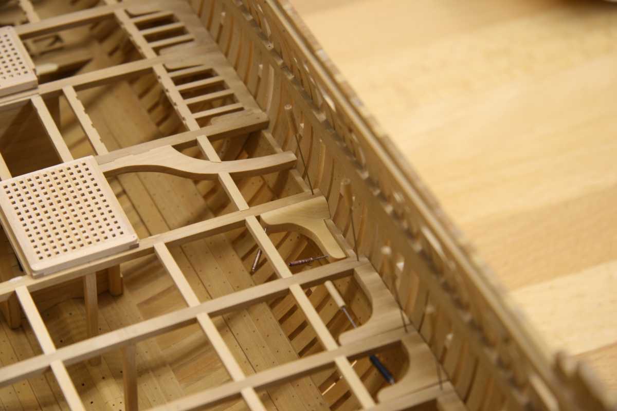
Meanwhile, more knee's opposing knee's gratings and so on. Everything is loosely fitted before marking the mortices for the ledges. Doing tasks in batches certainly speeds things up.

Remco
-
Thanks Duffer.
Your right Joe.....
So I continued and didn't change the mortices. Getting the round up of the deck into this special beam took some patience...

Remco
- Dubz, Piet, paulsutcliffe and 9 others
-
 12
12
-
I know there are drawings in the Naval Archive but accessing them for this may be too much to wish for.
Who knows, maybe Santa is generous this year
-
Thanks Mark
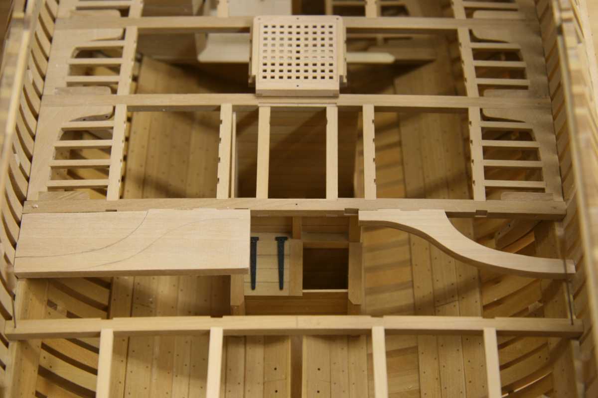
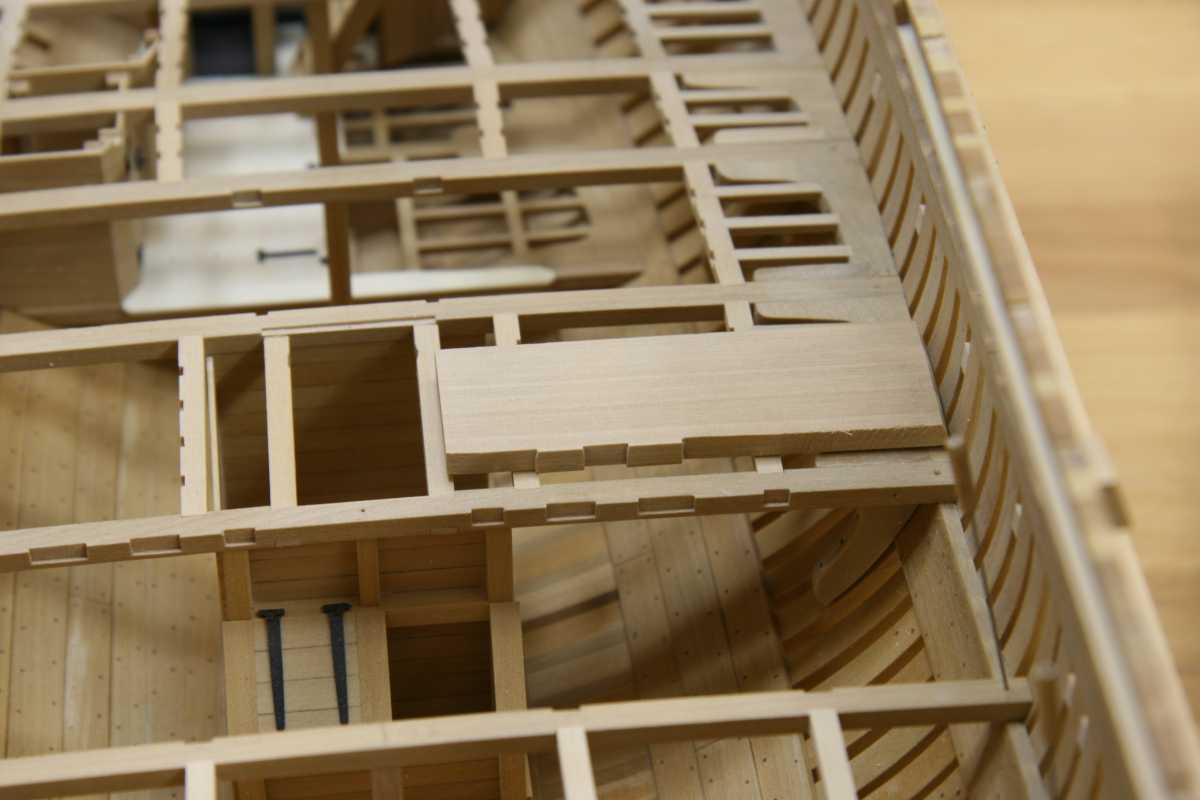
I have a question, without really thinking about it I cut the mortices for the tabs of the beam arm half blind, but when is was shaping the tabs of the beam arm I started thinking if this is correct. The tabs could also be the full with of the receiving beam. TFFM discribes the beam arm is bolted to the opposing beam so the half blind mortices would give extra strength but the whole fitting is different than the carling and ledges so maybe unnecessary complicated. Its just to know how it was on a real ship because once fitted the different is not noticeable unless one could crawl under the lower deck :-)
I haven't cut the thickness of the tabs yet so I can go either way.
Remco
- paulsutcliffe, fatih79, Elia and 1 other
-
4
-
You make it look so simple, but this must be difficult parts to make and fit so neat to the beams
Remco
-
Sweet!
So now you're planning on how you're going to make the locking mechanism for the loading door?
Remco
-
Good to see you back Mark, you haven't lost you touch, beautiful as ever.
Remco
-
-
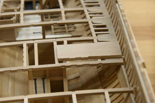
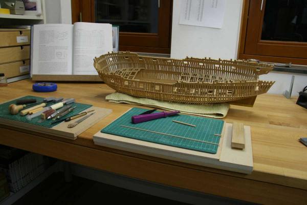
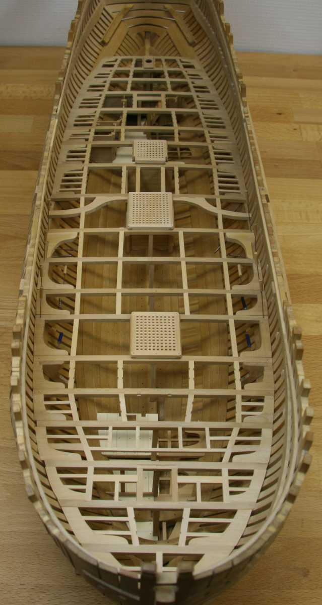
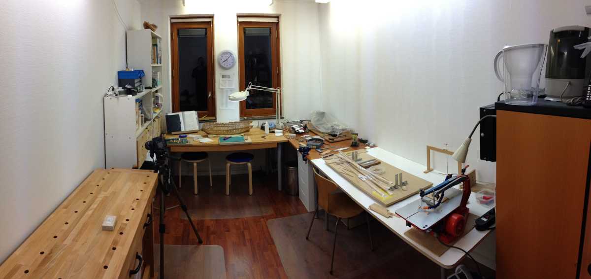
Martin, on the left is a workbench I only use for building full size parts like jigs and furniture.
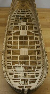
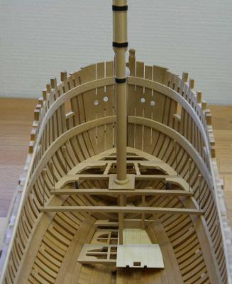
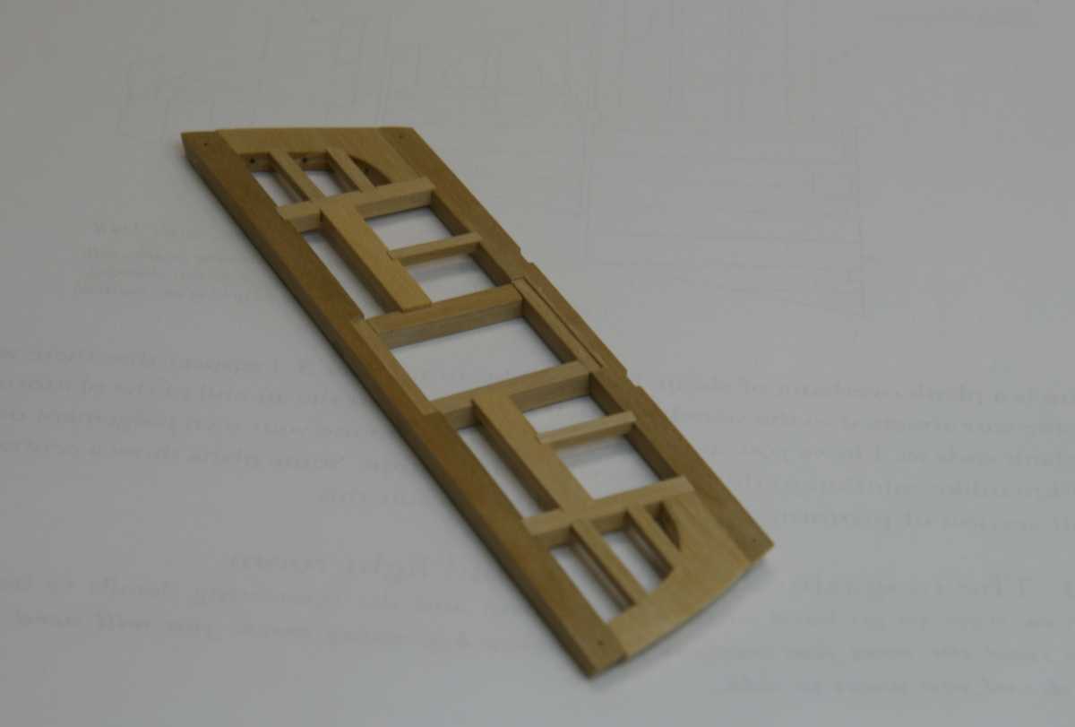
I had some alignment issues with the carlings so I decided to cut all the mortices for the remaining beams and marked them all using a batten. Important lesson to remember for the upper deck.... Pillars are installed temporarily and still need to be chamfered.
Remco
- gjdale, paulsutcliffe, Elia and 9 others
-
12
-
Nice close ups. All the details really come out well after the coat of primer, the metal sheets look is particularly realistic.
@ Andy, wow, yes, that's a possibility! Thanks for the links, it also reminded me of having read about these decals some time ago in another build.
Maybe here
 thanks for reminding Andy, don't we all hope to see some rivets
 Remco
-
-
Ed no magical powers, I did use a building board to erect the frames and to make measurements inside the hull. But whenever possible I take the model from the board and work seated.
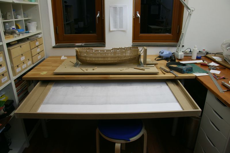
Ok, maybe the space are I do most of my work is tidy the rest of my shop isn't. Especially for you Joe I immediately took a picture as the shop is right now. A bit distorted as I made a panorama picture to capture the whole shop.

One might wonder why no storage on the walls, I had that in my previous shop and it takes away an enormous amount of light. One cannot have enough light :-) It looks small in the picture but the room is spacious enough measuring 4.40 x 2.70 m.
Remco
- Jorge Diaz O, Piet, mtaylor and 8 others
-
11
-
Thanks for the appreciation. Greg's right, starting with a cross section (and a cross section is already a big project!) is good advise.
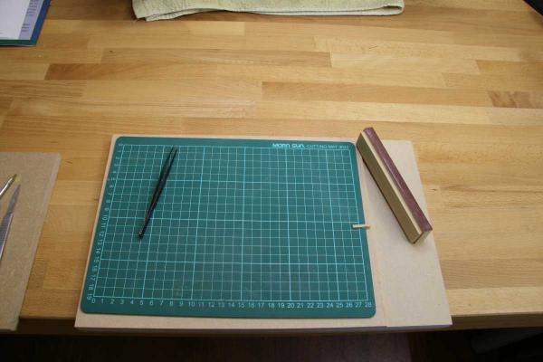
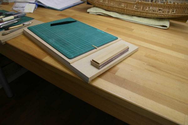
Today something different. For some time I've been using a small board as a movable workstation, so I can move is out of the way if I need to install something in the hull. As you can see I don't use a building board to hold the hull as I work mostly seated. The board is also used for my sanding block and today I added a small edge to is so it works as a shooting bord now. I had to adapt the sanding block so it will ride along the edge. A good sanding station helps to make perfect joints ( and sharp chisels....).
Remco
-
My two cents in the "should I buy the kit" discusion
With the knowledge I have now of the 'kit' I would not buy it again. Apart from the hefty price tag it's more of a scratch build starter package than a kit. And although all the parts are precut, Mr Hunt had no good control of his CNC router leaving ugly dents in every part. Cleaning up is tedious and will harm the overall shape of the parts. I stopped using them a long time ago....
Building the kit is just as complex as making it from scratch, so if I could go back in time I would:
Get the Swan plans from admiraltymodels.com
Get the Swan framing package from hobbymillusa.com
Get TFFM Vol I, II and III from seawatchbooks.com, well I got them as you need the books even if you have the 'kit' as the practicum won't take you all the way.
(ps just a happy customer from the above company's nothing more)
Buy yourself a good scroll saw and table saw, you can easily squeeze this into the budget of the kit price you've just saved from spending. And it's a good investment for future projects.
Take a plunge into the wonderful world of scratch building, it's not as difficult as I had imagined especially with all the help and knowledge here on MSW you can tap in to. And one other thing, if you mess up a kit part like the hawse timbers ( it took me more than one attempt
 ) you're in trouble. But if you make your own parts you just cut a new set and try again.....
Now lets get back on topic
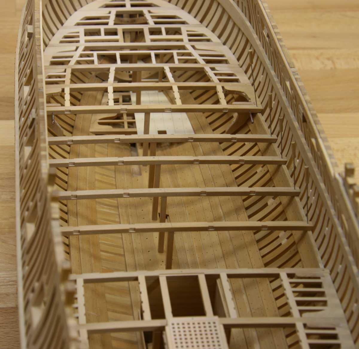
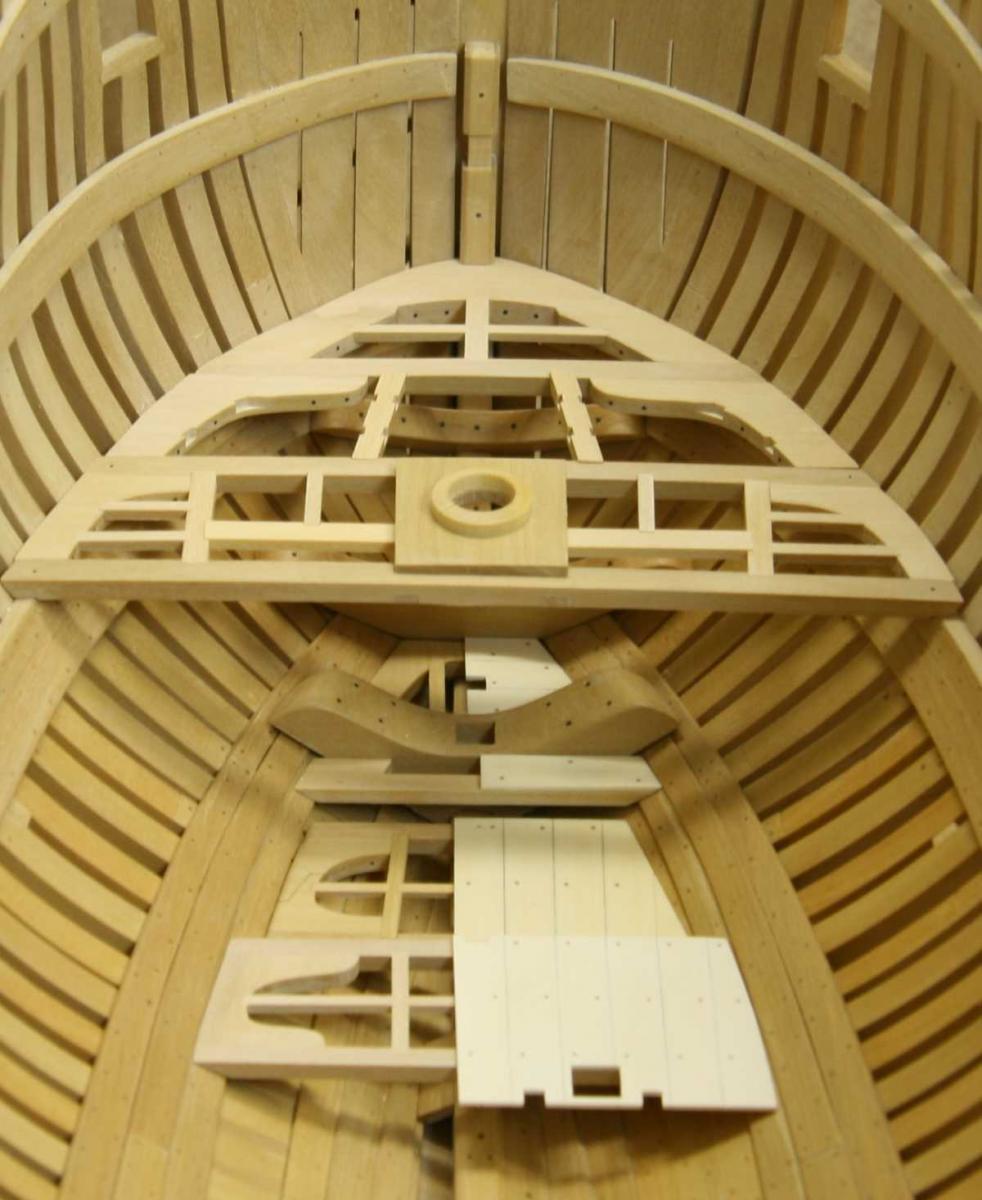
 Thank you Martin for your kind words.
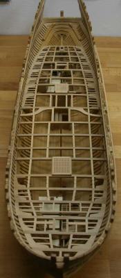
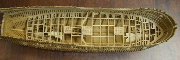
Current state of the lower deck. Progress is slow bud steady.

Remco
-
Wonderful Karl. The pictures taken at deck level look like there taken on a on full scale model.....

Remco
- Jeronimo and SawdustDave
-
2
-
John, I followed your build silently. She turned out beautifully, congratulations on finishing such a fine model
Remco
-
Piet, have you considered turning the torpedo tubes from a nice piece of hardwood?
Remco
-
Thanks.
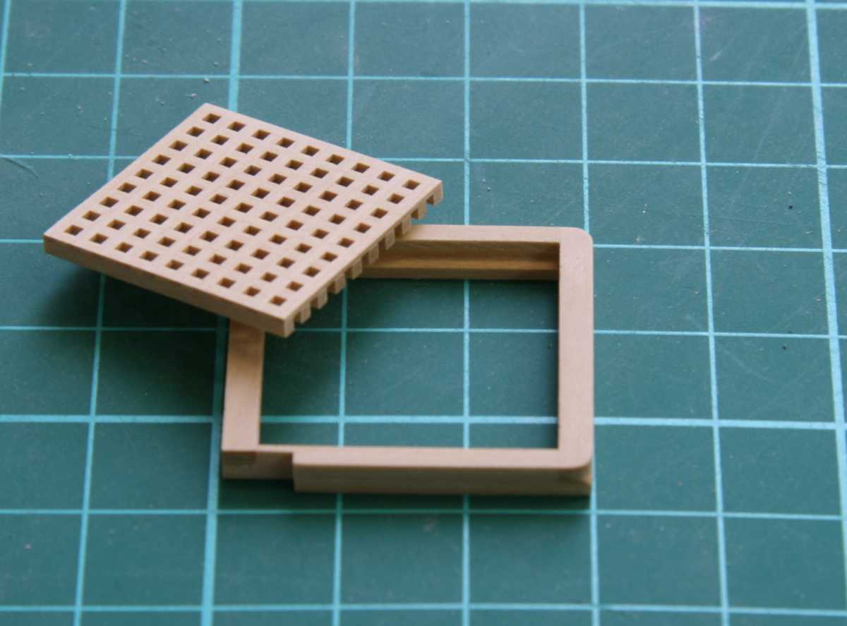
I temporary turned my attention to make the aft hatch and grating. Making gratings was one of the things I've been looking forward to making. I finally got around to set up my table saw to make the notched battens, it was actually less difficult than I had imagined. In the end I didn't use the special sled I had made, but just a regular cross sled with a small batten off set from the blade to make repeated cuts. I had to adapt the coamings to let the bitt pins pass.
A big batch of notched battens were made so I only need to do this once and have good supply to make all the gratings.
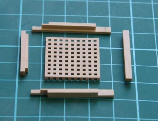

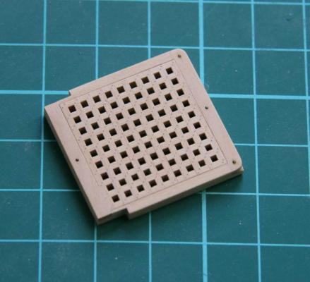
The nails are simulated with a graphite tipped needle, just like I did on the mast tops.
Remco
- SailorGreg, tlevine, butch and 21 others
-
24
-
-
Thanks for the warm welcome back guys! Really appreciated.
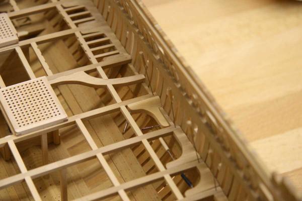
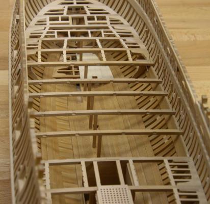
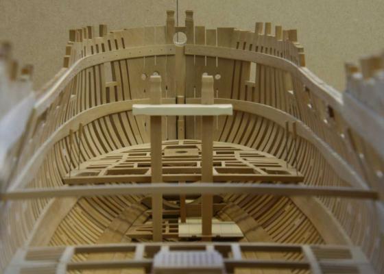
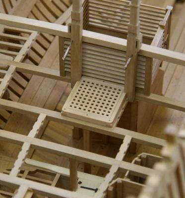
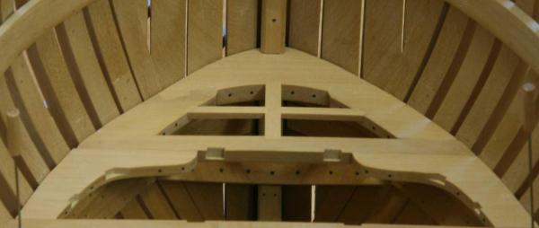
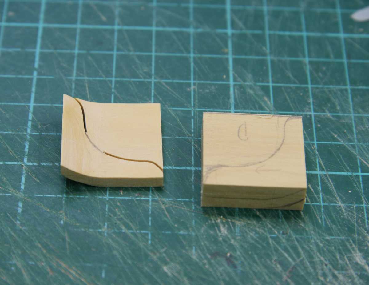
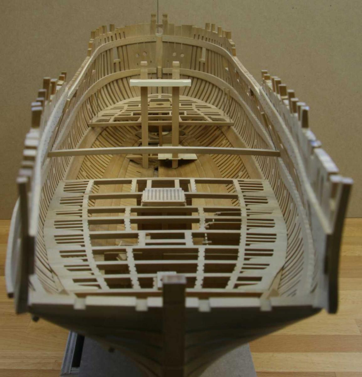
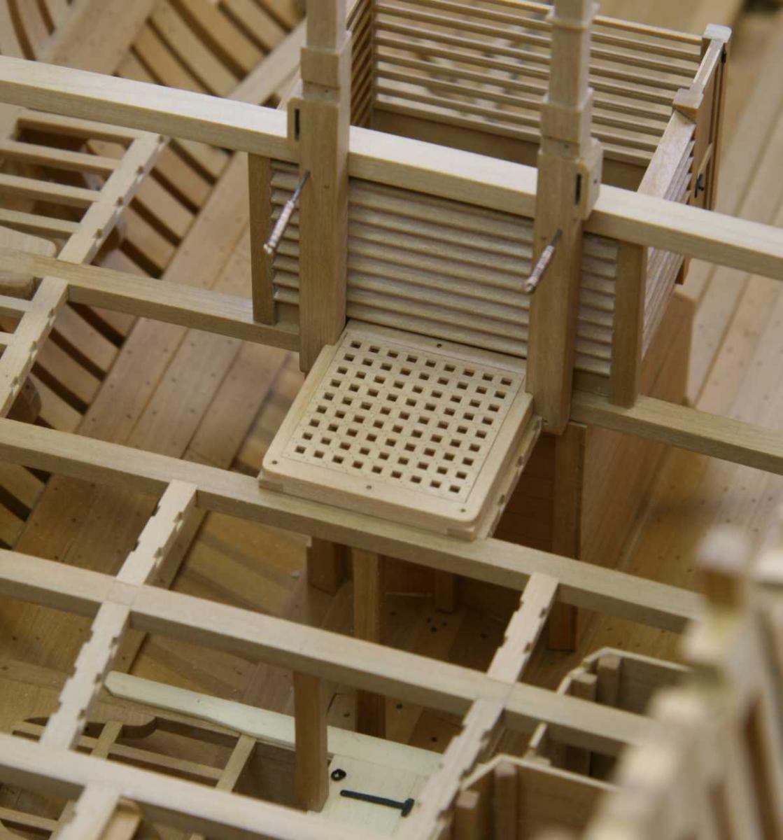
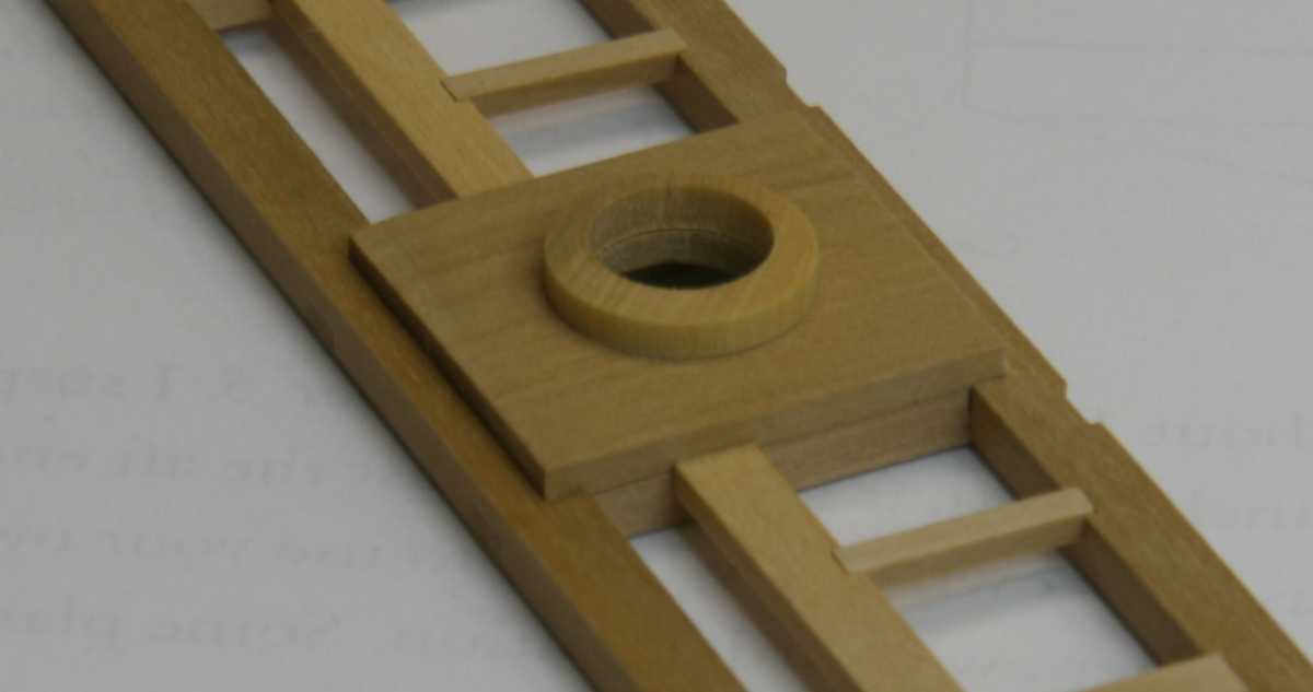
I made the carlings and ledges around the mast partner. As two of the carlings are half lapped under the beams and the mast partner itself is let down 1" on the beam this makes for some interesting cutting and fitting....


The mast wedges will be simulated by scoring the ring with a graphite dipped scalpel blade (actually it's already done but this other ring is fitted to the mast)

Remco
- Dan Vadas, Wishmaster, Elia and 13 others
-
16
-
I really like how the hatches for the dingy compartment turned out. Nice touch to an already very nice build.
Remco
-
I got fed up with the plastic kit and it served it's purpose, I back working on my KF.
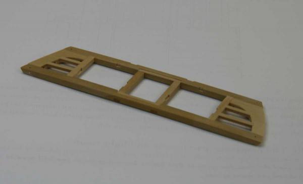
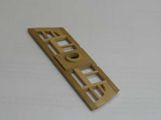
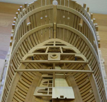
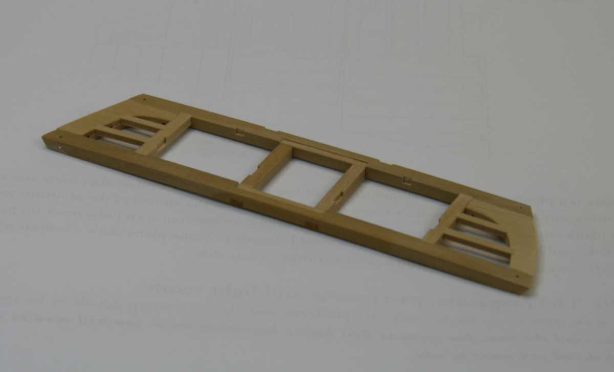
Shaping the parts at the bow is a little tricky but fun especially with the scarph joints and the mast partner that has it's carlings cut from the onder side of the beam. Partially fixed partially test fitted here's the progress to date. Having the fore mast finished already helps to align all parts.
Nils, thank you. Indeed the frame work is close to the real thing but not completely. I did not make the chokes as separate parts but they are part of the frame timbers.
Remco
- Mirabell61, dvm27, paulsutcliffe and 10 others
-
13
-
For those looking for an alternative. You can get rivets as decals. http://www.archertransfers.com/SurfaceDetailsMain.html I used to use this and there pretty cool. Saves a ton of work and the results are very realistic.
Remco
- harvey1847, Piet and avsjerome2003
-
3


HMS Kingfisher 1770 by Remcohe - 1/48 - English 14-Gun Sloop - POF
in - Build logs for subjects built 1751 - 1800
Posted · Edited by Remco
Thanks guys.
Greg the pins are easy to make, I think they rank amongst the top 10 most used tools in my build.
Ben, with my scroll saw they were relative easy to make and there were no remakes :-)
I couldn't find an appropriated sized piece of brass for the iron knee so I made it from boxwood and tinted it black with Fiebing's leather paint
I'm also doing lot's of mortice cutting for the remaining carlings and ledges.
A little off topic, but it was time to make a better storage for my chisels. They used to wander over my bench with the tip protected by a little piece of isolation foam. This was a nice little project, keeps them safe and organized
Remco