


AntonyUK
-
Posts
1,189 -
Joined
-
Last visited
Content Type
Profiles
Forums
Gallery
Events
Posts posted by AntonyUK
-
-
Hi Vaddoc.
Nice build so far. Like the CAD work.
I got a set of plan's from the Albert Strange trust. Albert Strange – Albert Strange – his life, boats, art
They are copy's of the original set of plans. Quality is good and they come in PDF format. Original size. But as you say there are issues with them.
Regards AntonyUK.
-
Thanks Kenny.
Another Cad File for your inspection.
Thanks for looking in.
Regards AntonyUK.
- Keith Black, PaddyO and druxey
-
 3
3
-
Hi again.
Thanks John.
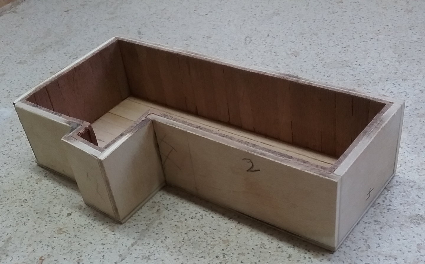
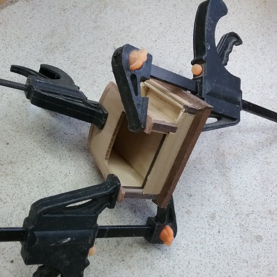
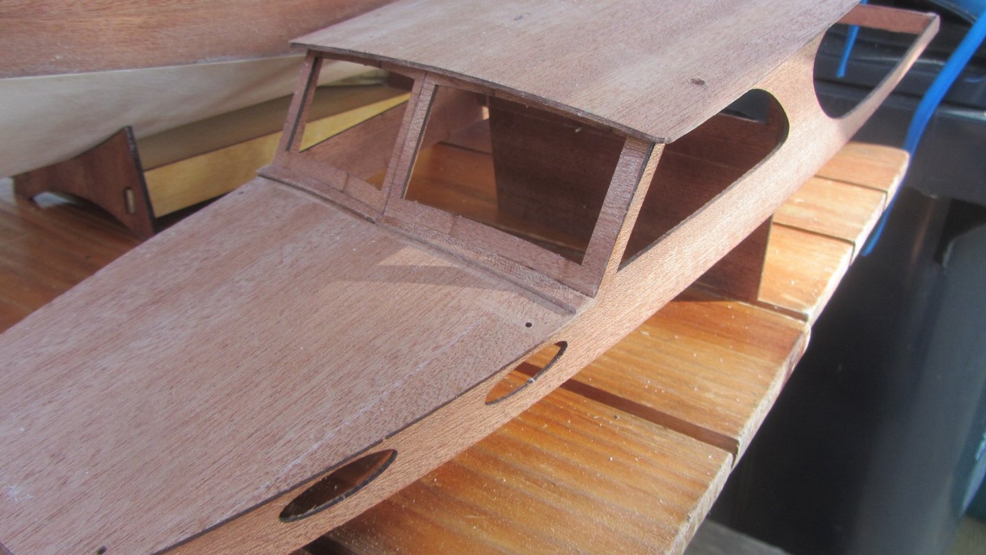
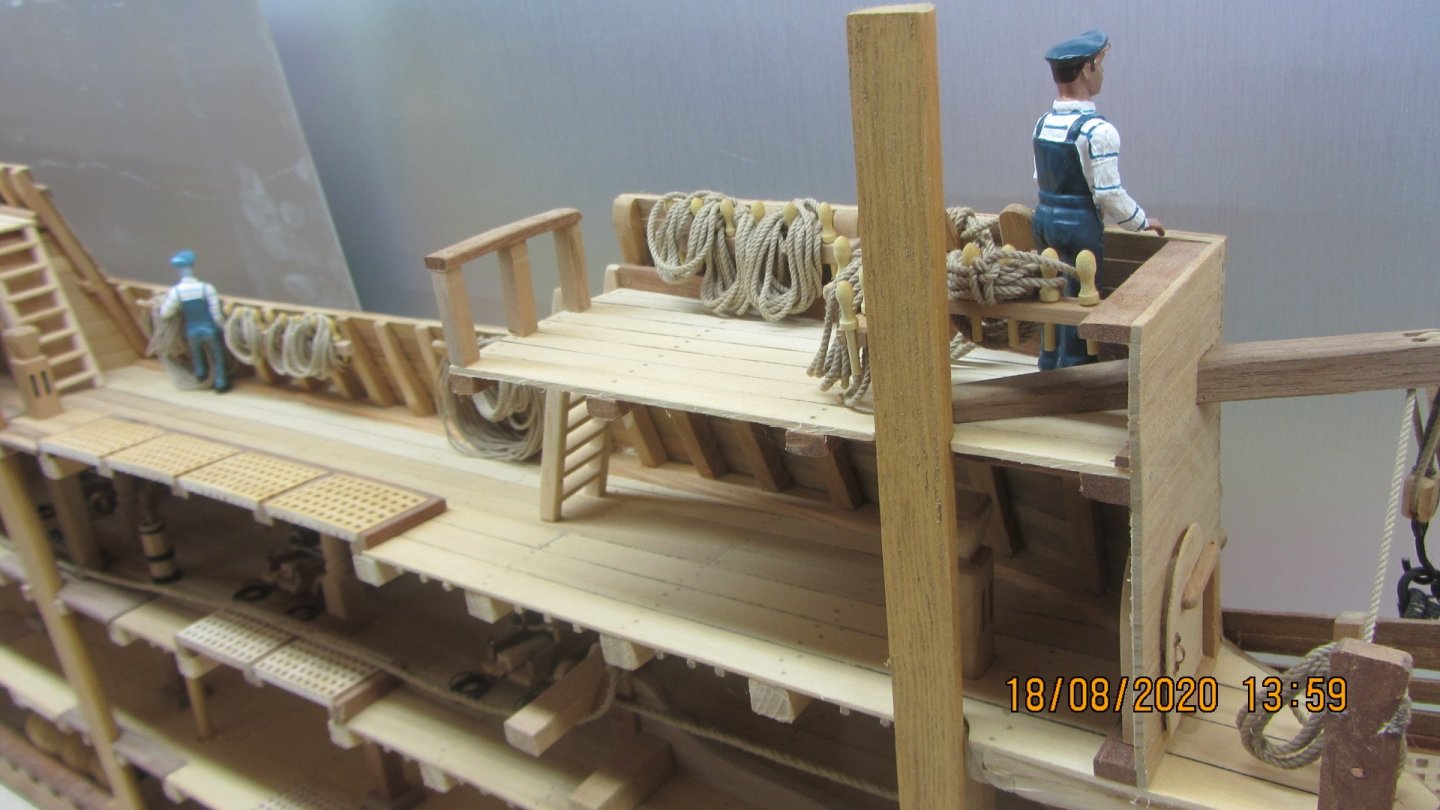
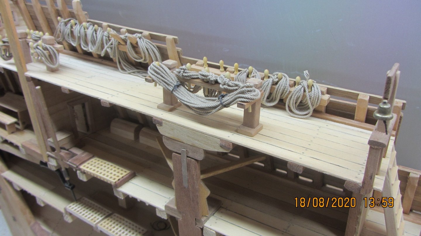
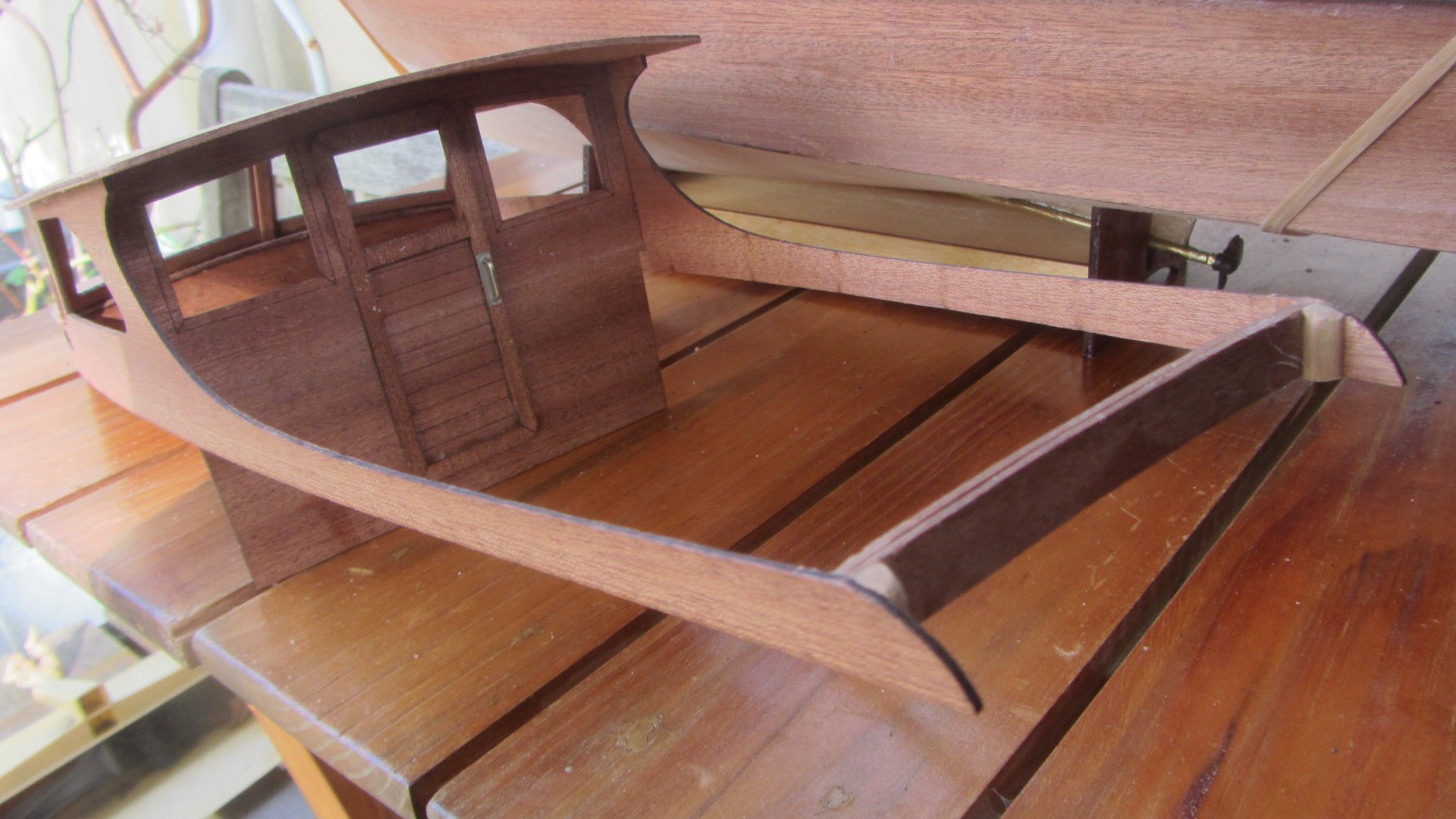
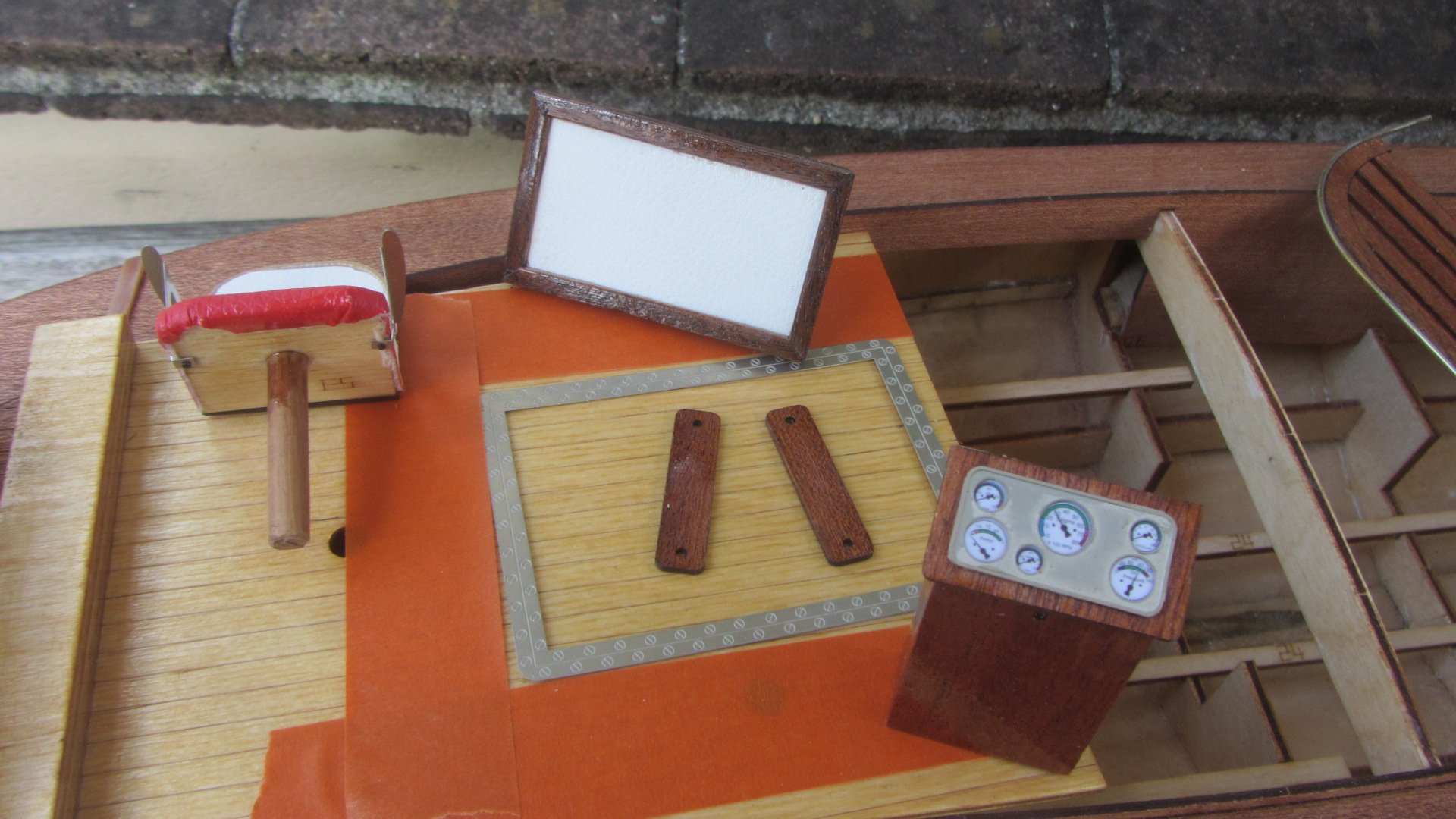
Ok been making the deck Furniture this week Basic cutouts with the laser and strip wood glued in place. All the photos are still work in progress ATM. Lots of finishing and bits to be added EG Hatch runners, Handles, More strip wood on Skylight. Portholes.

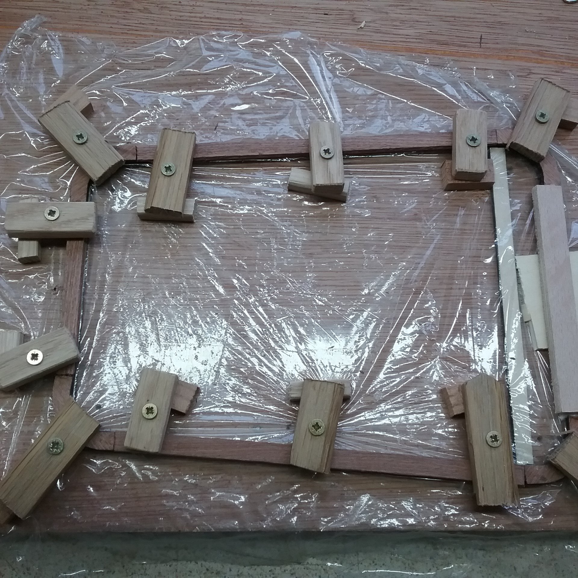
Above is cockpit area seating handrail still in its jig Corners laser cut and hand cut strips on the straight sides and back. Cling film so no glue sticking to the jig.
Above. Cockpit well Planked but not finished. Got to add Engine control's and gear shift/throttle leaver.
Forward hatch very much work in progress ATM.

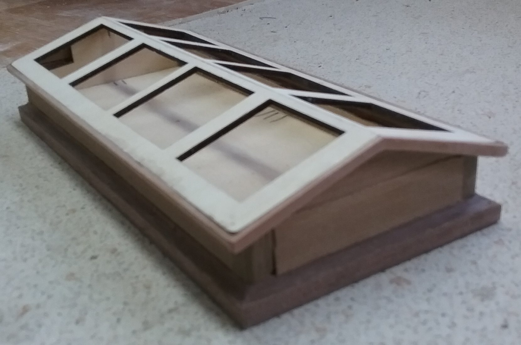
Above. Skylight with only sides and end planking in place. Not making the skylight with openings for ventilation.

Above. Cockpit seating area wall with skirt (Planking thickness). Two bits of thin ply wrapped around jig while glue sets and Handrail glued in place. Again Lots of work in progress.

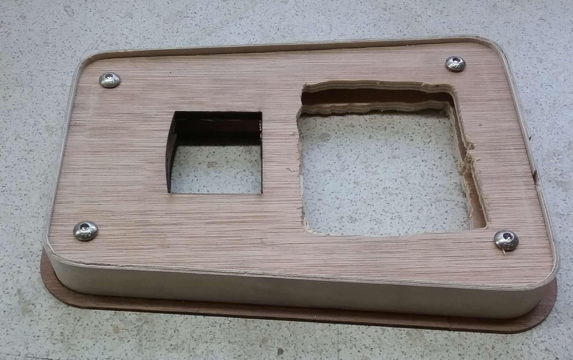
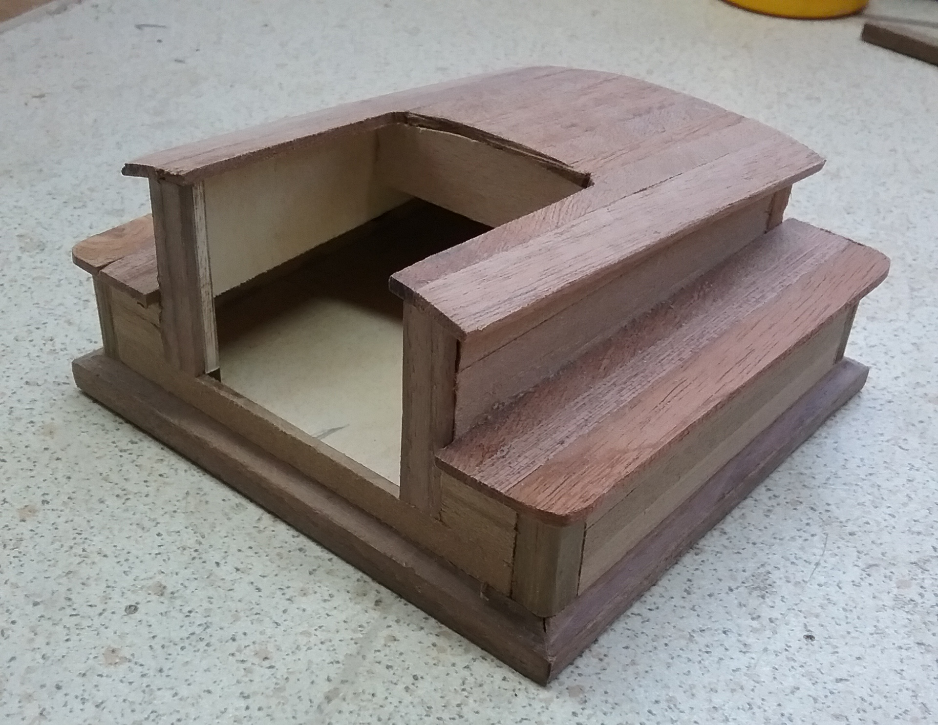
Above. Main companion way hatch. Tried to copy the same construction methods as Leo's team used.
Next job will be to Epoxy the false bulwarks(Plywood) onto the fibreglass bulwarks. This will give me a nice flat finish to mount the stanchions onto.
And start to finish the deck furniture. Ongoing for the next few months.
Regards AntonyUK.
-
Thanks John.
On 10/20/2025 at 12:33 AM, Jim Lad said:Just catching up, Antony. She's coming along beautifully.
John
Another update. I have started on the deck furniture IE Hatches, cockpit area and the rest of the Cover boards.
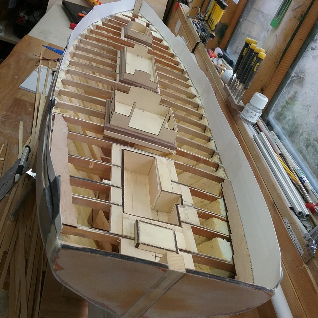
Not in place yet. Only for show and photo.
All laser cut from 3mm plywood.
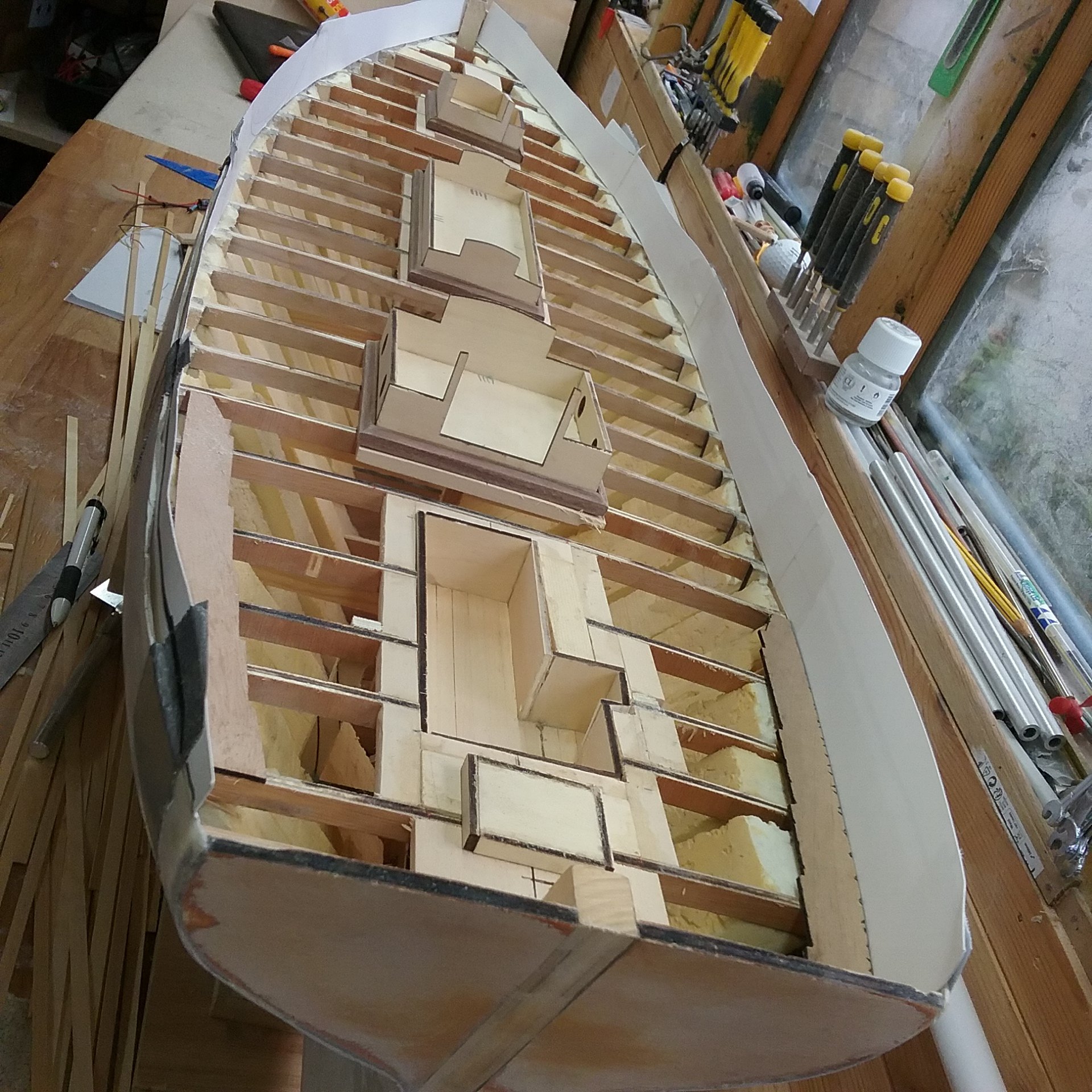
Deck furniture supports in place.
Templates for inner bulwark face. will be cut from 1mm plywood and fixed in place with resin. So when I cut the waterways there will be no gaps. I hope.

Next it will be the strips of wood on the deck furniture and the cockpit area. followed by the bulwarks.
Thanks for looking in. AntonyUK.
- MAGIC's Craig, KennyH78, PaddyO and 6 others
-
9
-
Hi again.
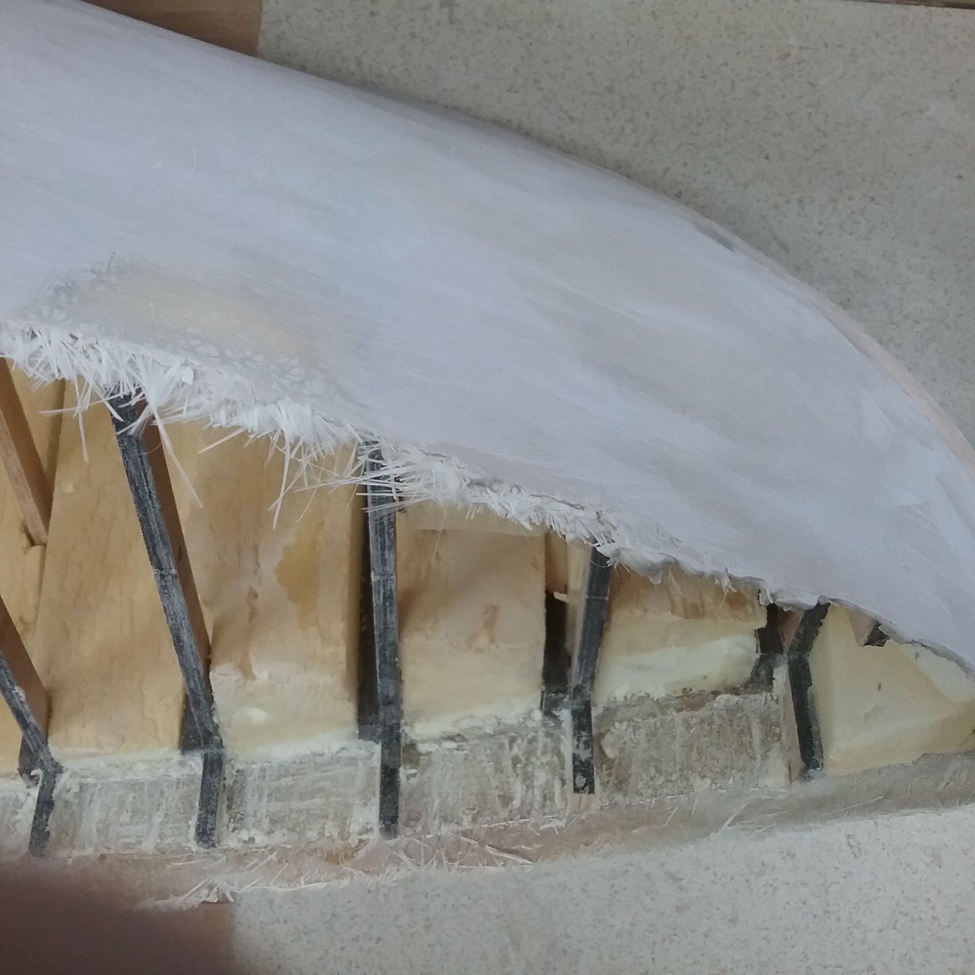
All excess fibre glass trim removed with Dremel and cutting disc.
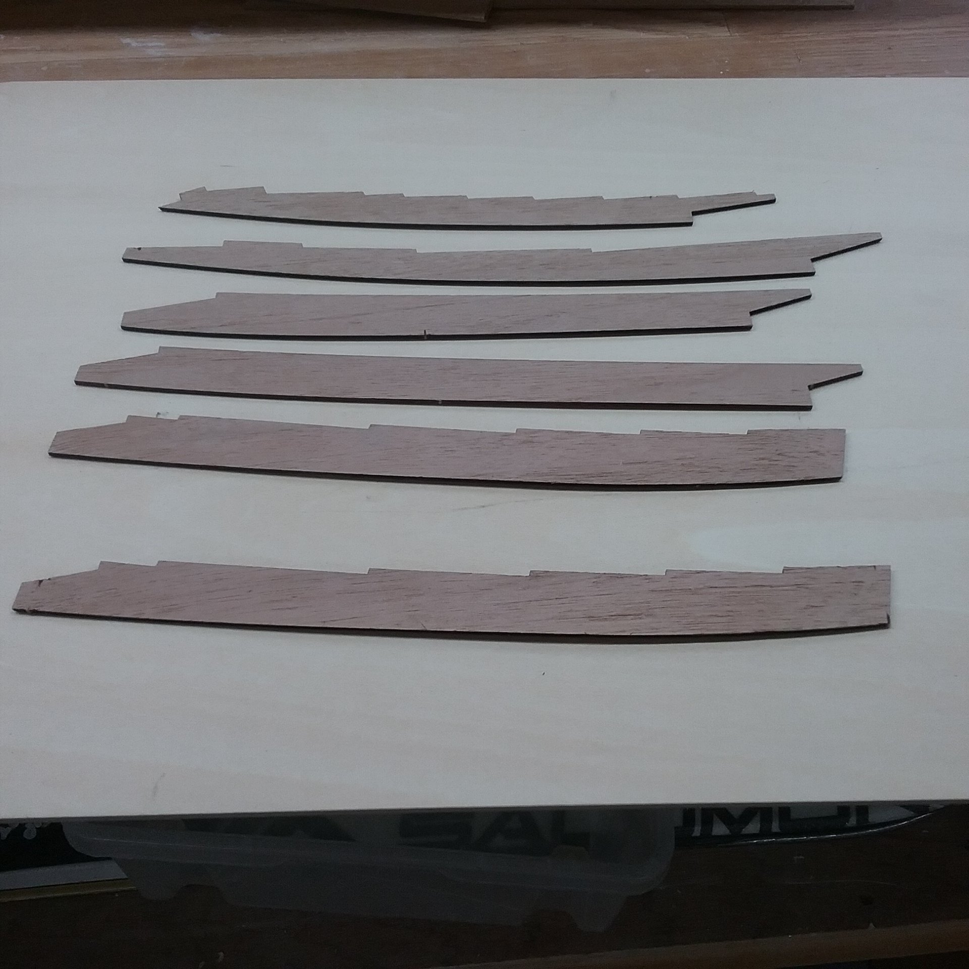
Laser cutting Walnut Cover boards out of 2mm Walnut.
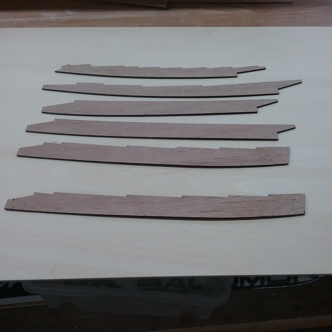
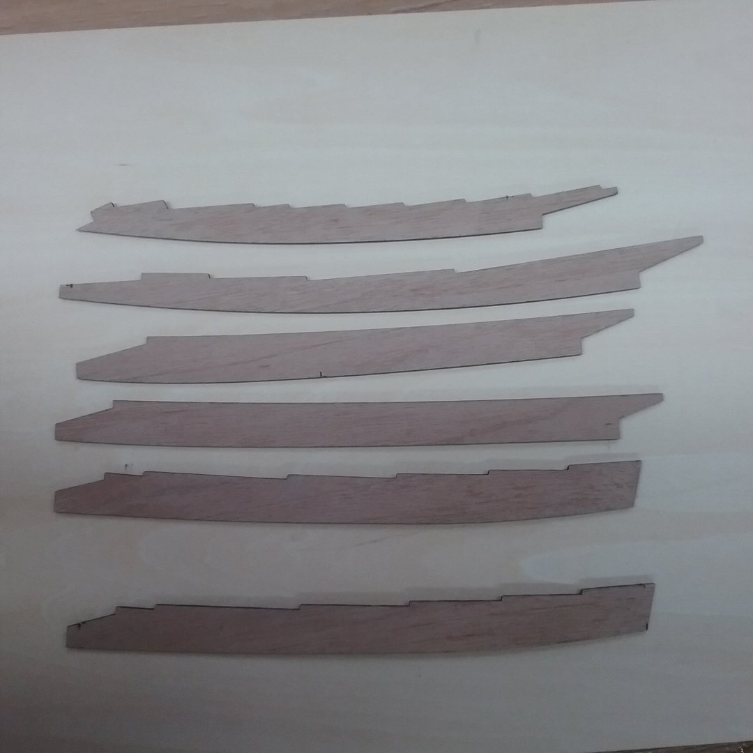
Got 4 more to cut out but run out of Walnut.
While awaiting delivery of timber. Will give the shed a good clean down.
Not yet cleaned up.
King planks are next out of the same Walnut.
Then the lining of the bulwarks on the inside.
Regards AntonyUK.
-
Good Morning.
First I apologise for the Big gap in my posting. My wife has had her Hip replacement and I was doing the cooking and housework for 3 months.
Have little time to spend on the build. And Yes the hip replacement went very well. Good old NHS.
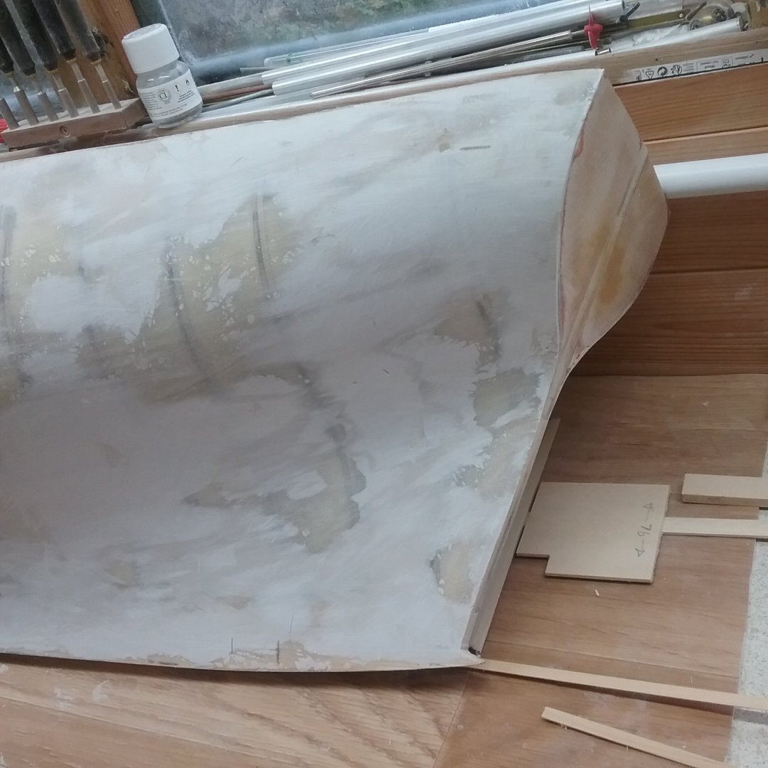
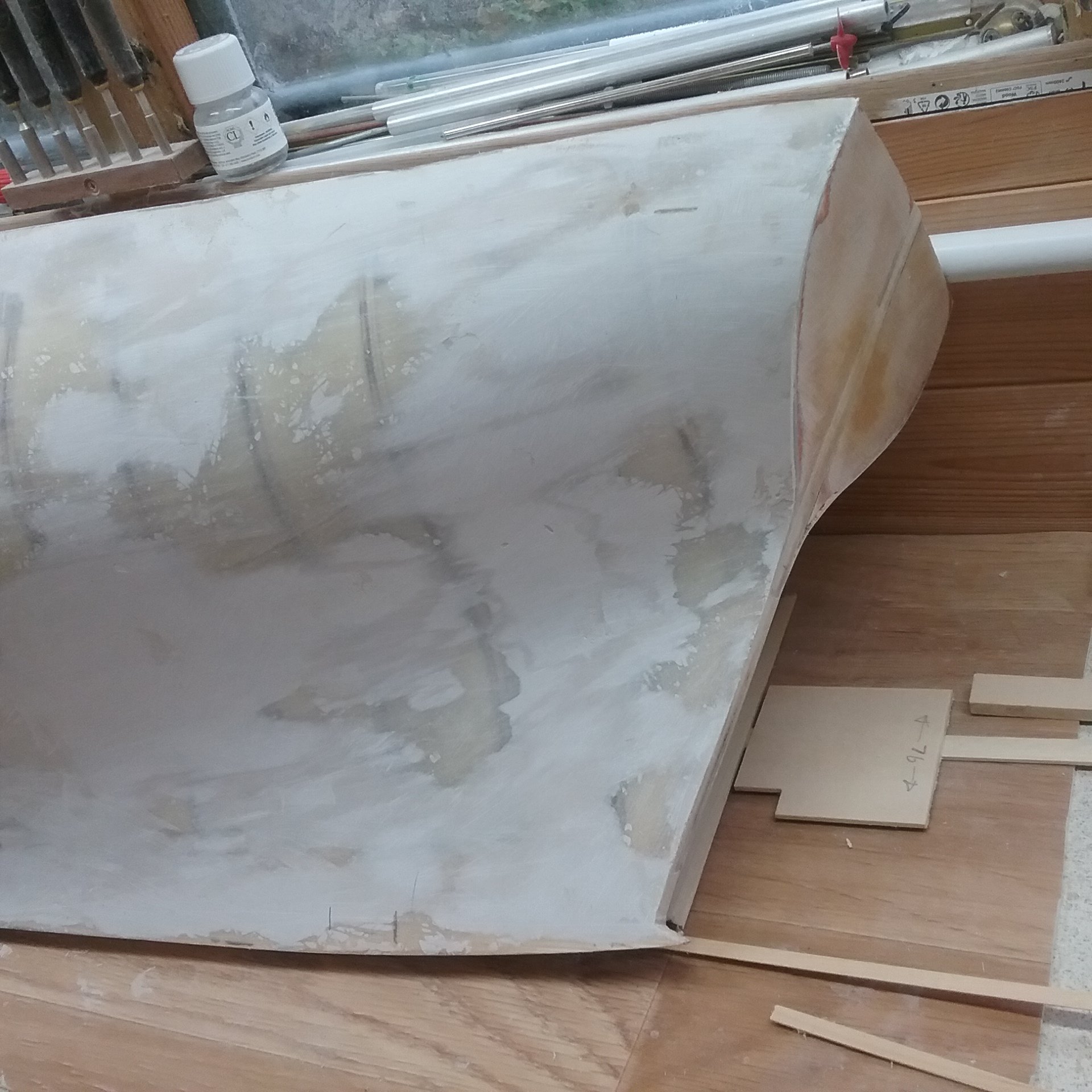
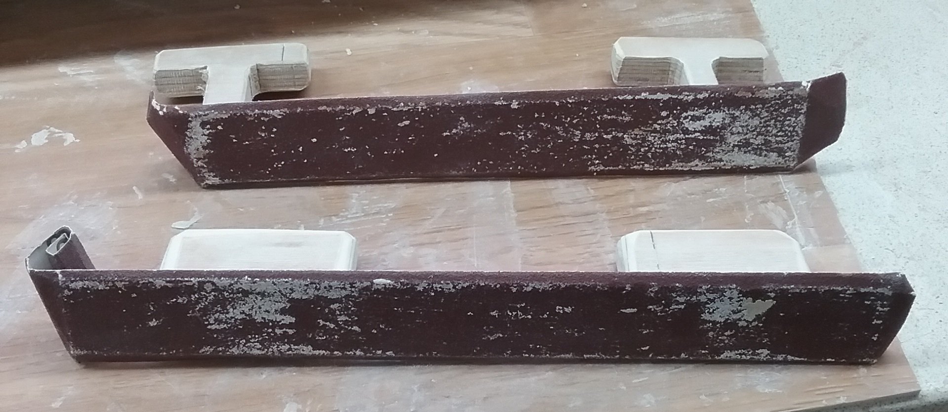
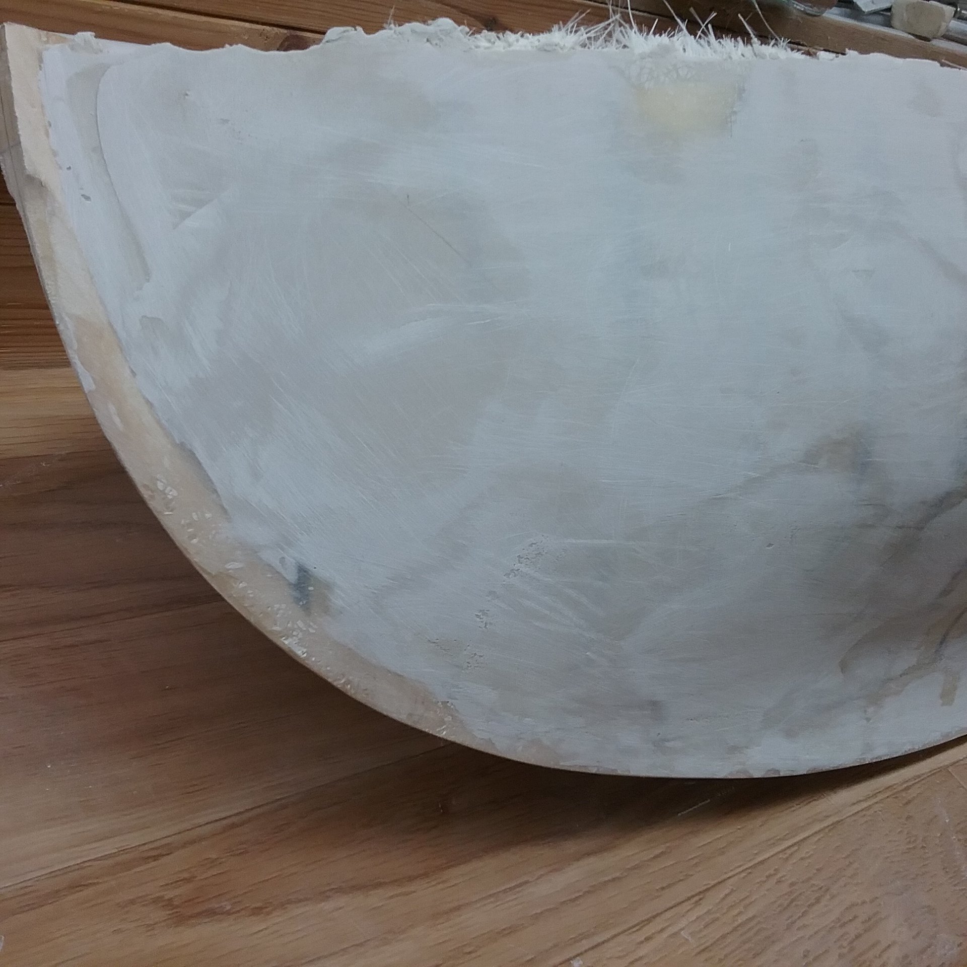
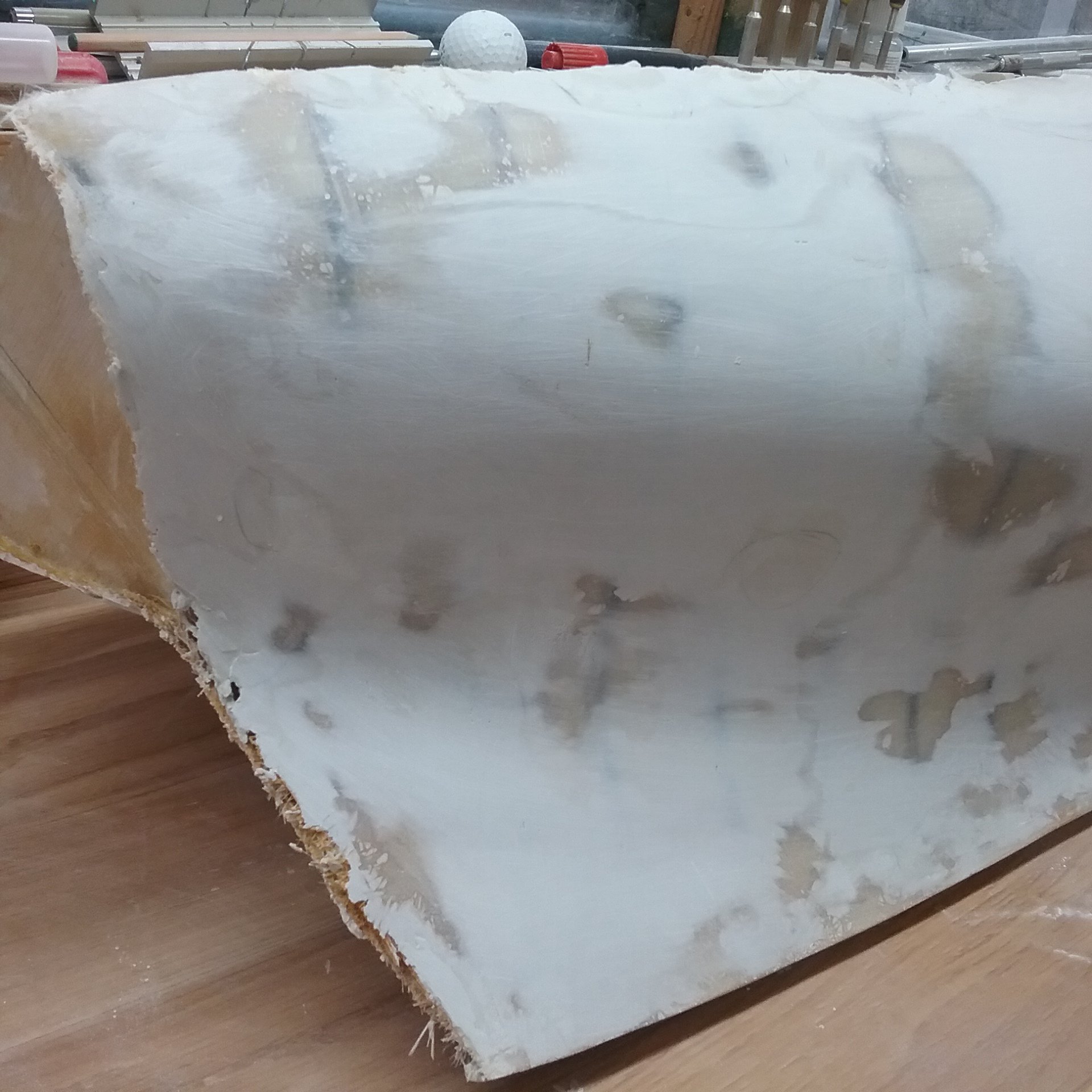
OK the update. Hull covers with 2 layers of mat and then sanded to remove any bumps that should not be there. IE were the glass overlaps.
Then I started covering the hull with a filler section by section. then sanded most of it off using the sanding boards below.

These worked better than any other tool I tried.
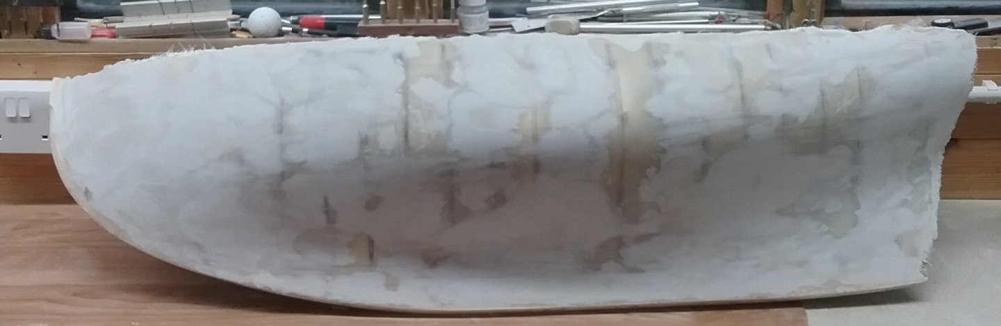

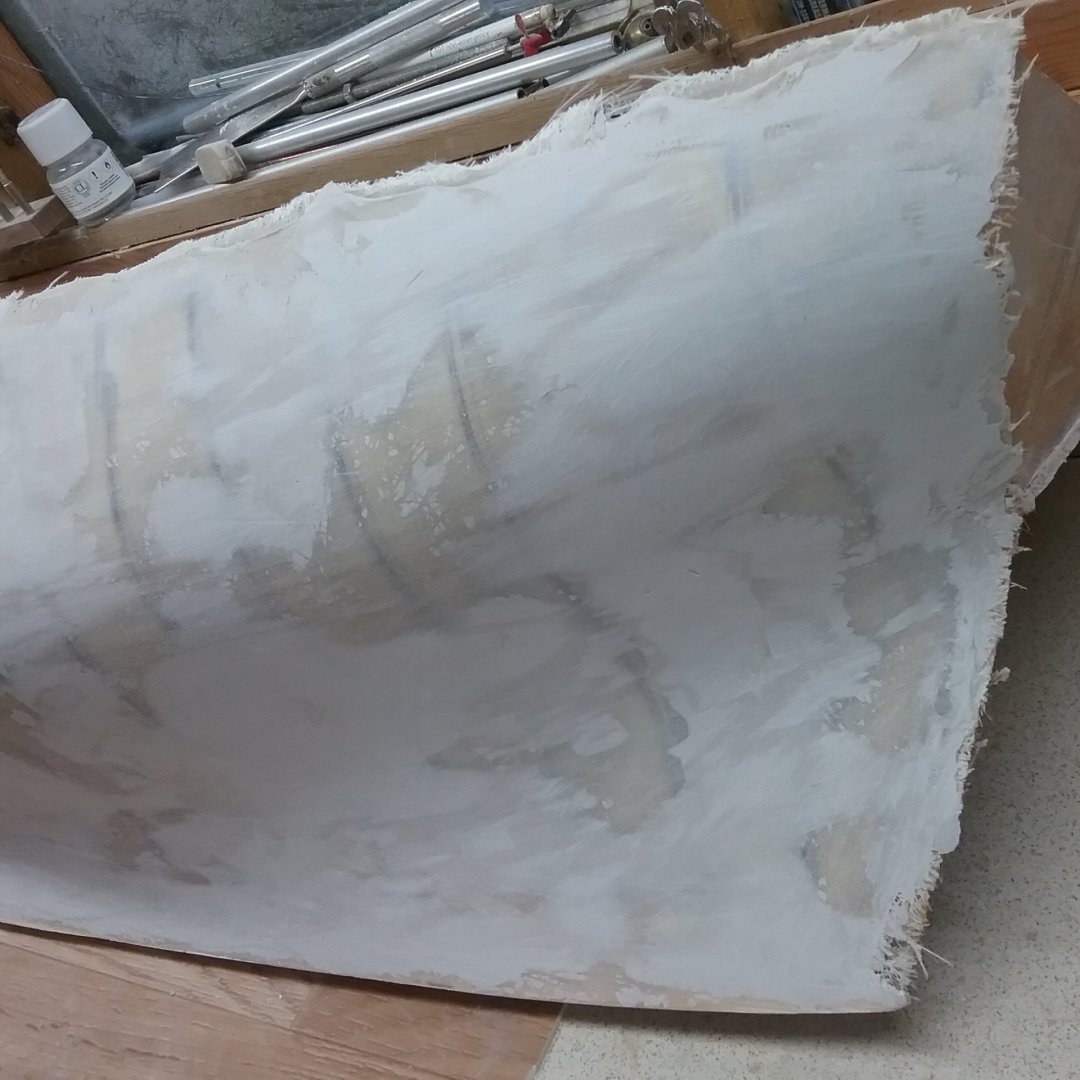


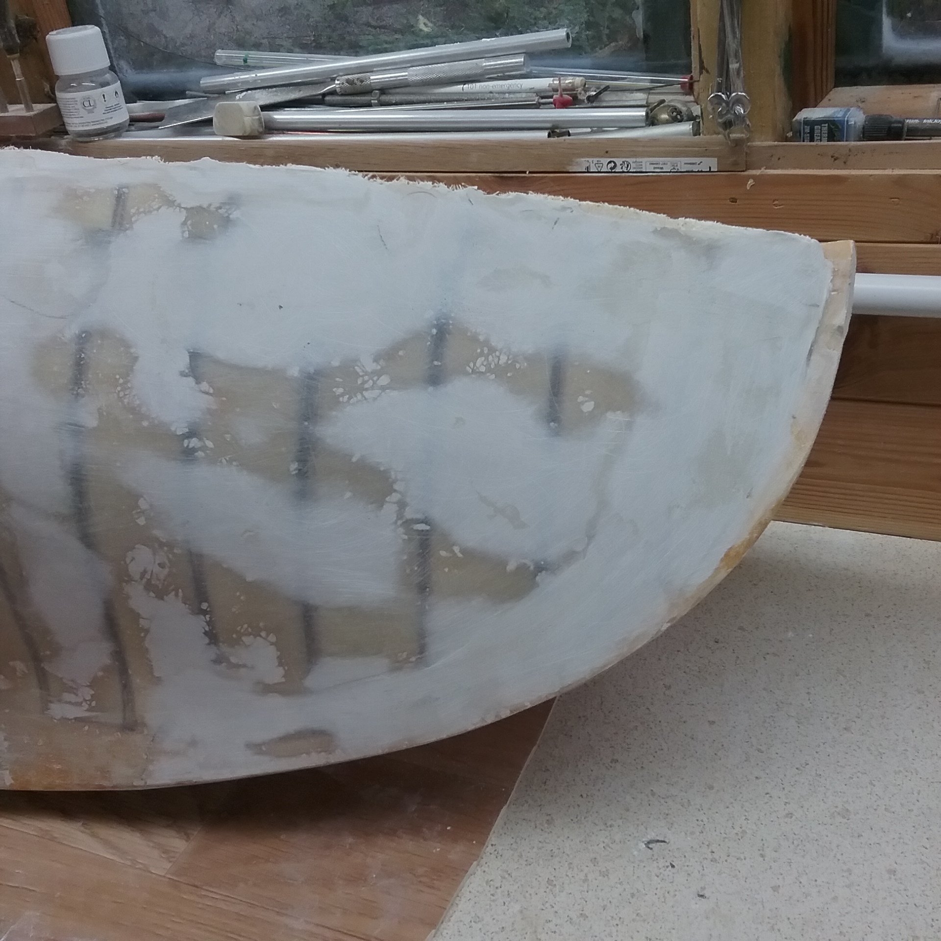
Removing the foam @ the bulwarks.

The hull will be left as it is for the time being. 100% sure if I finish it off now it will get damaged during the build. So final filling and sanding (repeat) until smooth and ready for paint job. Will paint it the same colours as Leo did.
Next job will be to construct a cradle to sit the boat in during the rest of the construction.
Thanks for looking in. AntonyUK.
- druxey, Keith Black, Mike Y and 6 others
-
9
-
Hi Vaddoc.
Thank you for your kind words.
Yes its a Static model.
Good advice on cleaning uncured epoxy.. Yes its my first time using the stuff.
Only Glassed one side at the moment as life gets in the way. or should I spell it with a "W"
The Plans :- The trust has all the plans of the boat and the ones I ordered are Accommodation Plan which has a Top view and a side view.
lines Plan.
Construction Plan. Top view and a side view. that shows the Deck beams and a centre section side view.
Table of offsets.
Detail sketches Showing 5 sections across the boat.
Sail Plan.
and a Mid section scanting's.
The Plans are full size all from scans original of plans,
Hoping to carry on next Wednesday as got lots on ATM.
Thanks for dropping in.
AntonyUK.
- Keith Black and vaddoc
-
2
-
Hello again.
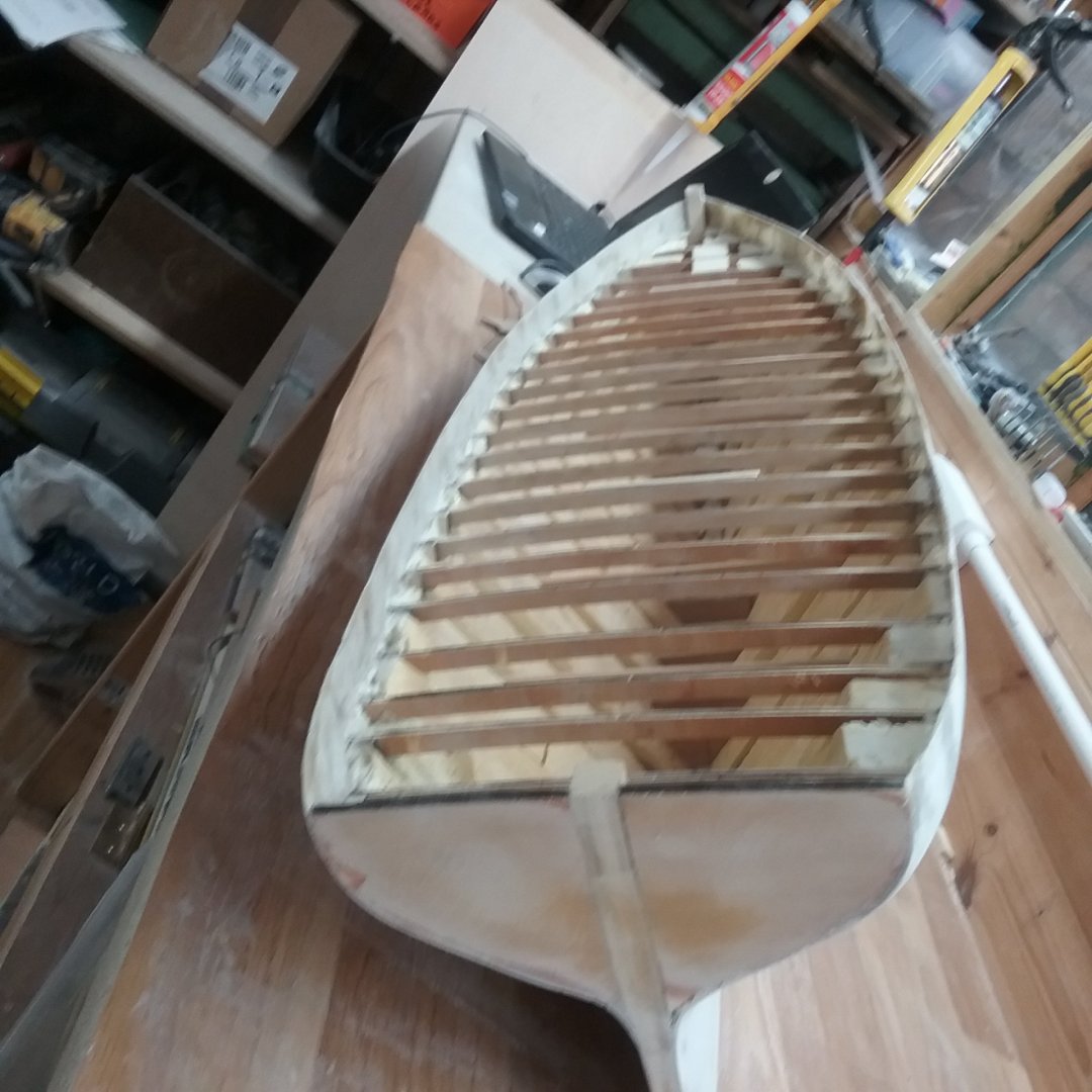
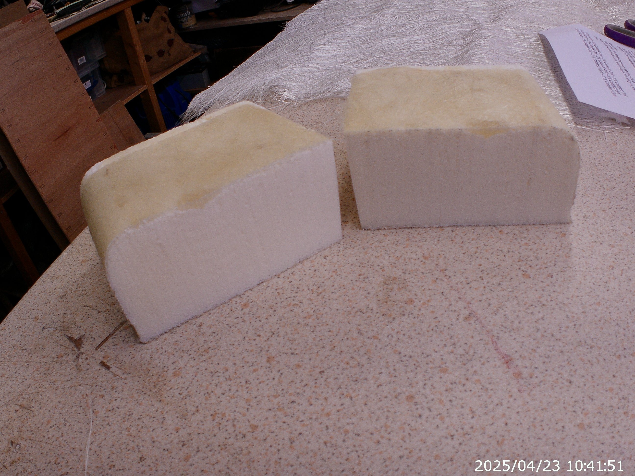
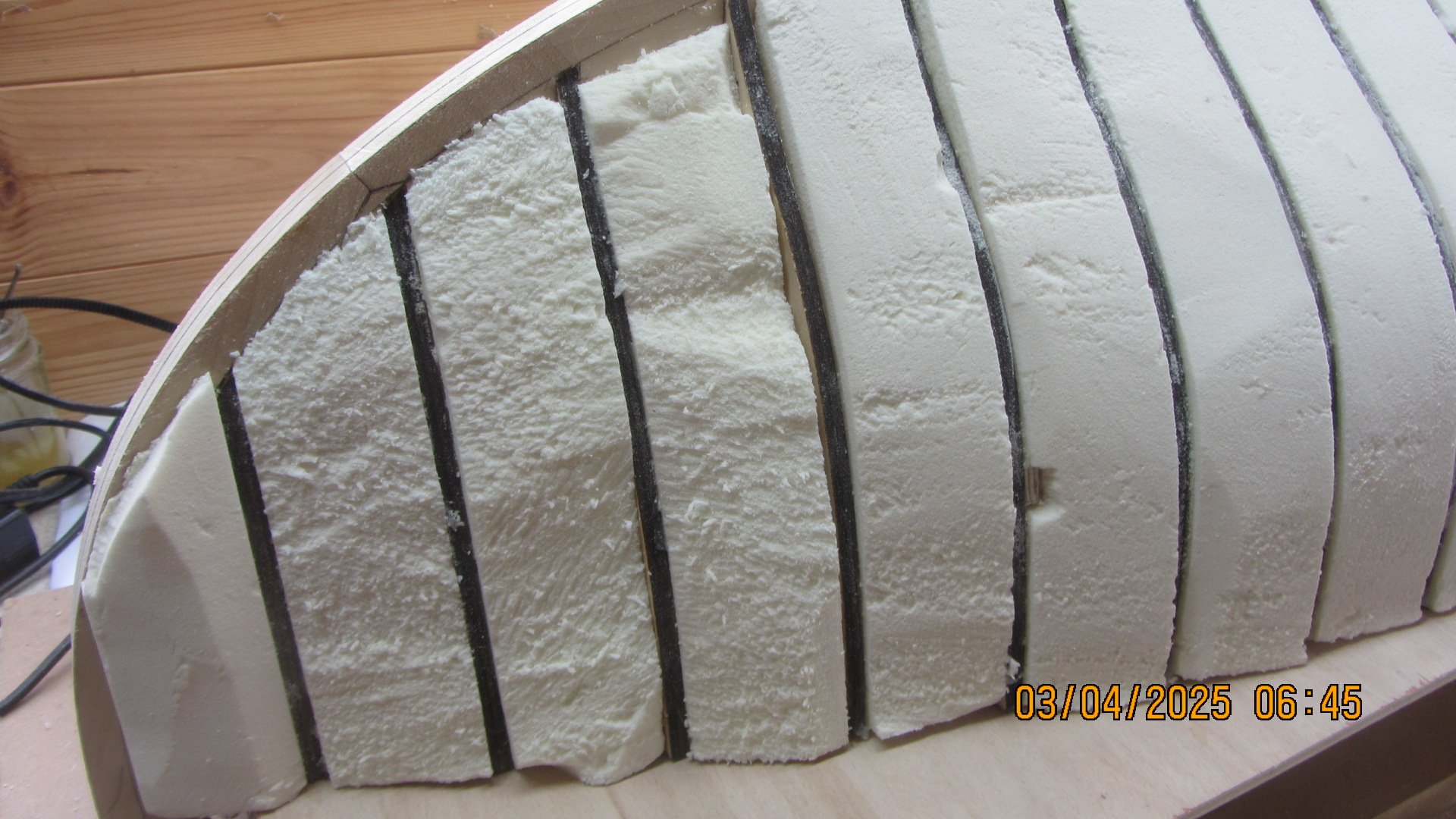
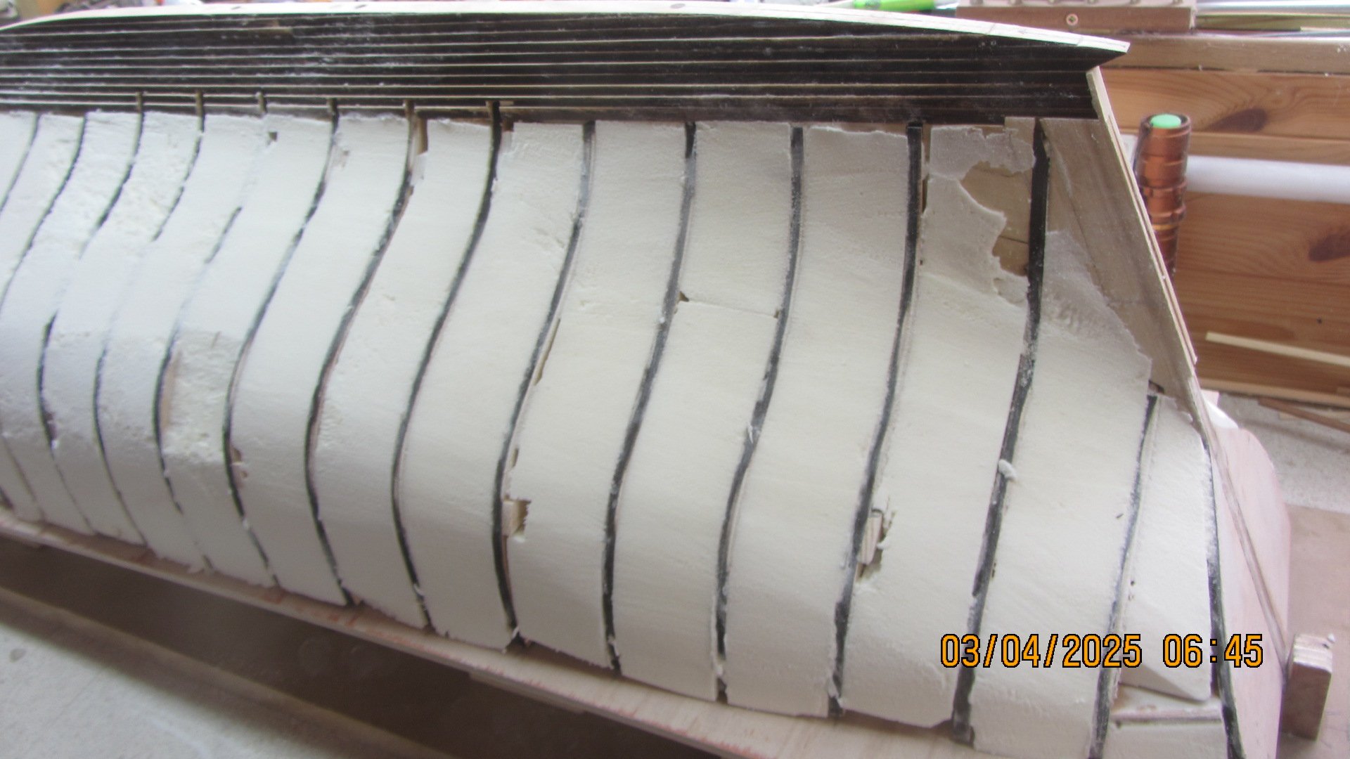
A change of plans. After testing polyester resin on the Polyisocyanurate foam it showed no signs of melting the foam.
I just wet the foam with the resin then added 300g chopped strand mat and wetted it through.
Left it 24 hours and sliced it through with a bandsaw.
So I will Not be using the plaster of paris to give the hull a firm surface for finishing.

Looks good to me
")
So I will apply 2 layers of 300g matting and sand to a good fare curve mabe adding more matt and resin or filler if needed. then I will spray a grey gel coat onto the sanded surface and fine sand to a finish.
then a white gel coat and fine sand and polish. I am hoping that I can cut the planking seams in with a diamond edge and fare curve plank. Will test this on some scrape before attempting to do it on the hull.
This fibre glassing is all new to me. Any advice ?? .
Thanks for looking in.
AntonyUK.
- Keith Black, yvesvidal, GrandpaPhil and 3 others
-
6
-
Hi Andy. from the SouthWest.
A little update.
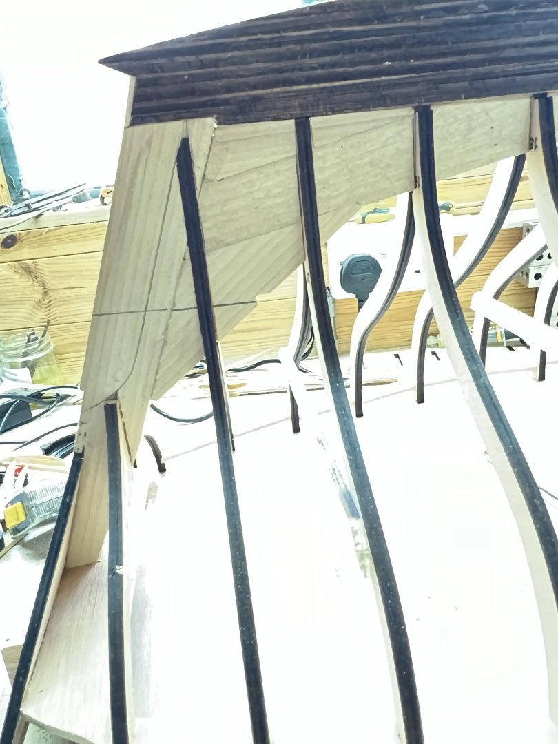
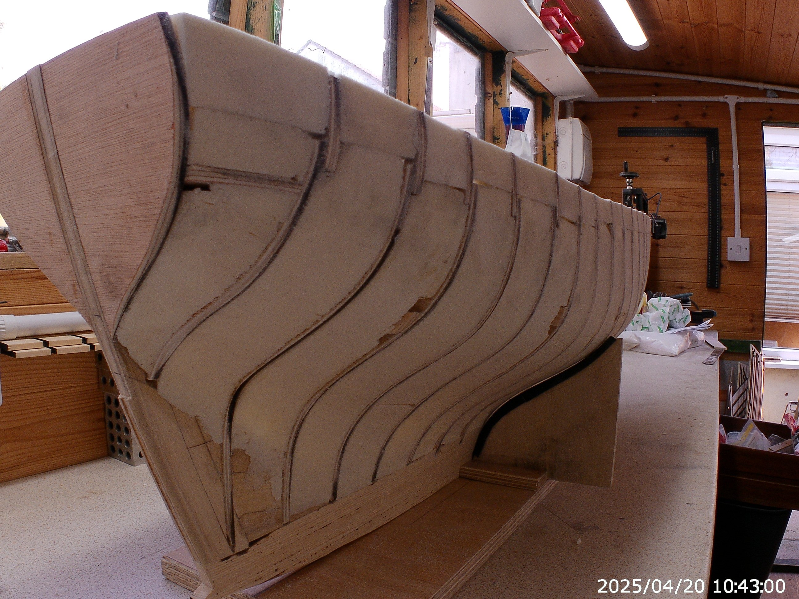
The deck beams and Stanchion post are added to the hull. The gaps between the Stanchion posts were filled with Polyisocyanurate foam and trimmed.
This was then sanded to its final before covering with plaster of paris bandage.


Now for the messy bit. Covering the hull with the plaster of paris bandage. That's a tomorrow job.
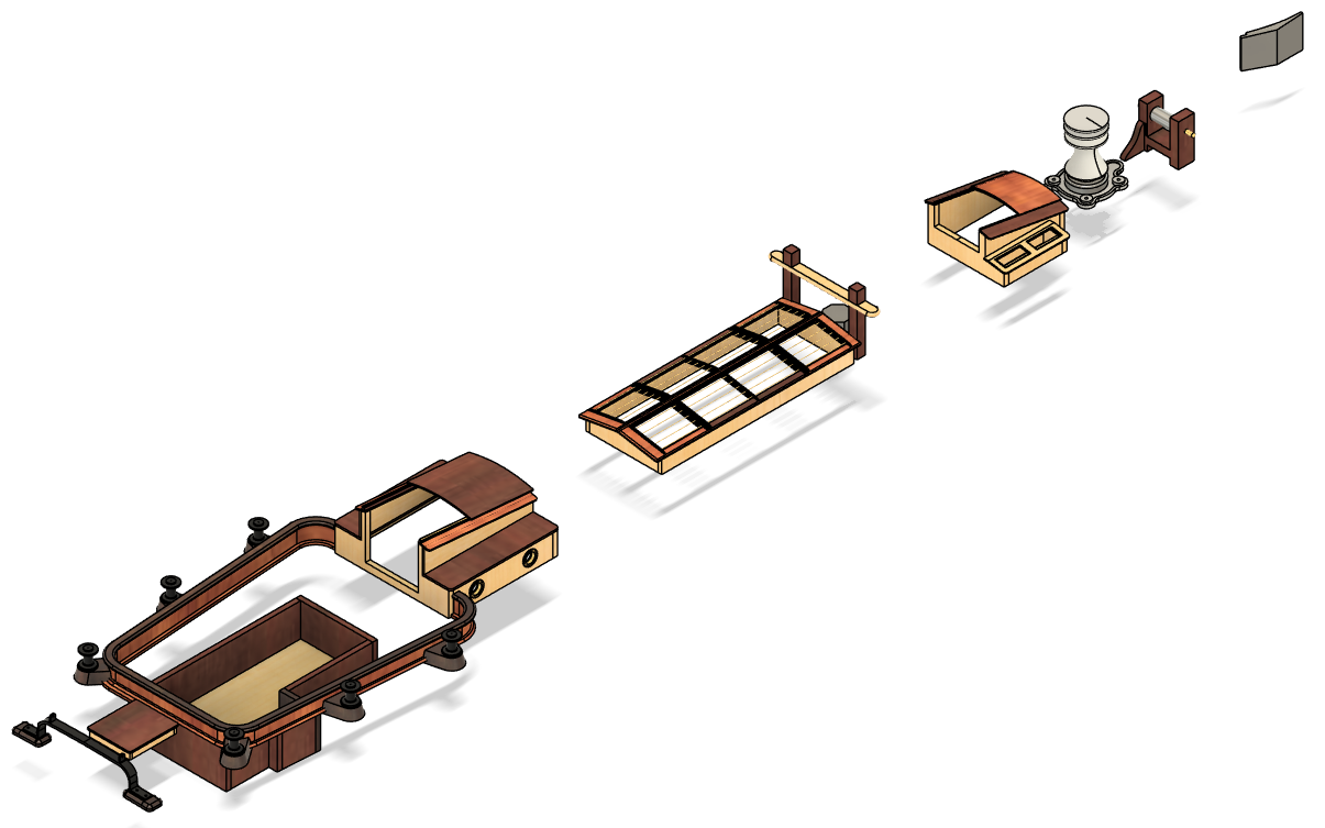
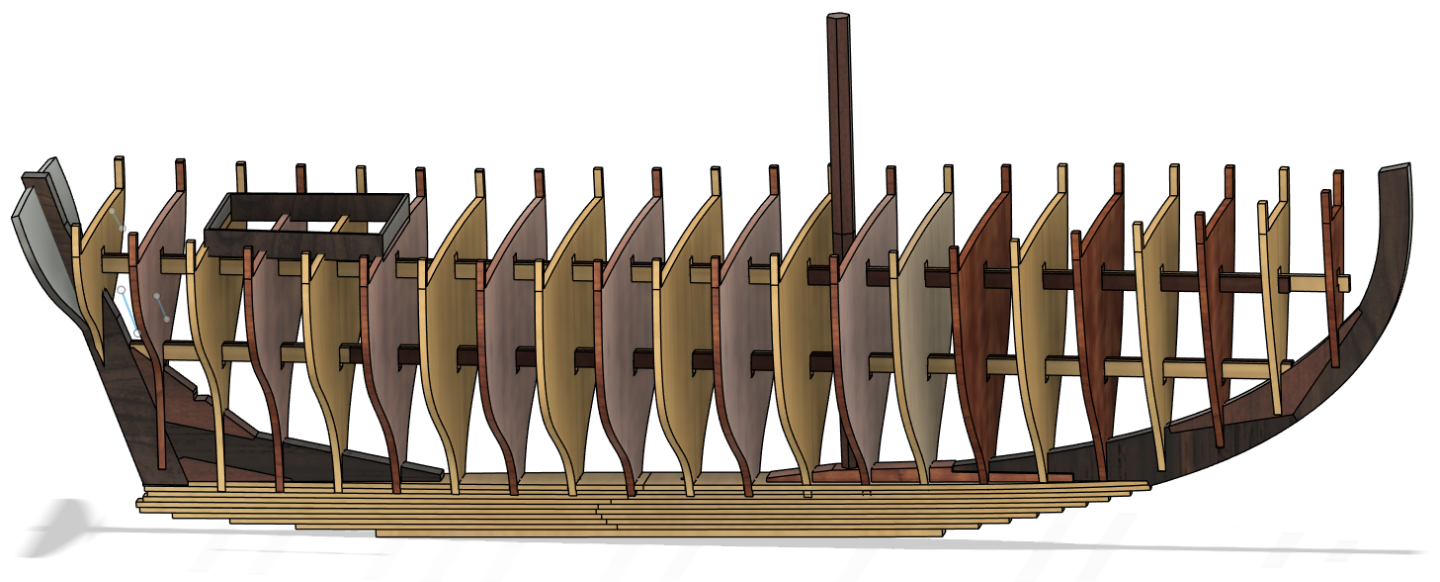
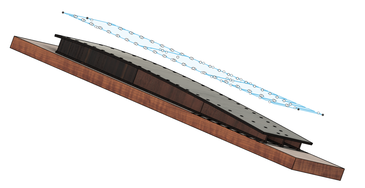
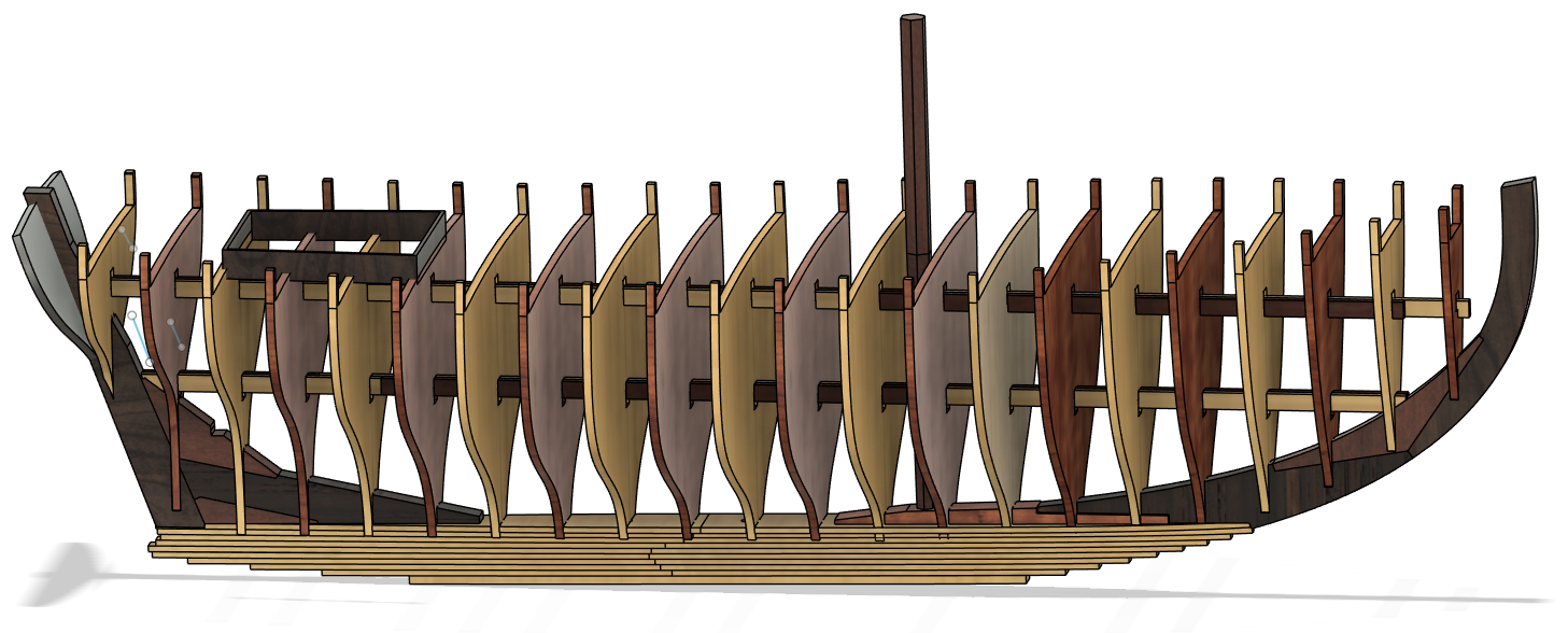
Another CAD view of the assembly.
Thanks for looking in. More updated as I progress.
Regards Antony UK.
-
Good morning.
Just a little insight into how the drawings are created.
I use Fusion360 Hobby Home version.
The plans were imported and scaled to the correct length at the waterline. Then there positions were adjusted to match together so that when you rotate the drawings it looks and reacts as it should in 3D.
All the Components then have Drawing plane's on all X Y and Z planes added(Just a habit encase I need them latter on)
Each part has its own drawing so that I can use Origin Shaper add-in to export the SVG files in the next stage.
The parts are drawn one at a time in the correct order so I can see them to check on the fairings and assembly alignment.
A few screenshots.

The Keel is made using a bread and butter construction. This gives me a true shape and is easy to fare when it comes to the sanding. Used dowels to get the alignment spot on. The layers are 4.2mm in thickness. and the bottom one is 6mm thick.

Sternpost is made up using 4 parts and and I used 16mm thick timber. All the parts were marked with a laser and also marked the rabbet line at the same time. parts were cut with correct grain direction.
Final fitting with file and chisel to get the fit.

The stem was done using the same method as the Sternpost. Using 14mm thick timber and the mast step was 21mm timber.

The assembly matched together.

Assembly with Frame drawings. Showing the lines very nicely.
The frame drawing were put onto a sketch which is the size of my laser. this made it easy to manipulate the parts ready for Shaper to do its magic.

The inverted building Base.
That's it for now.
Regards AntonyUK.
- Ronald-V, vaddoc, Keith Black and 5 others
-
8
-
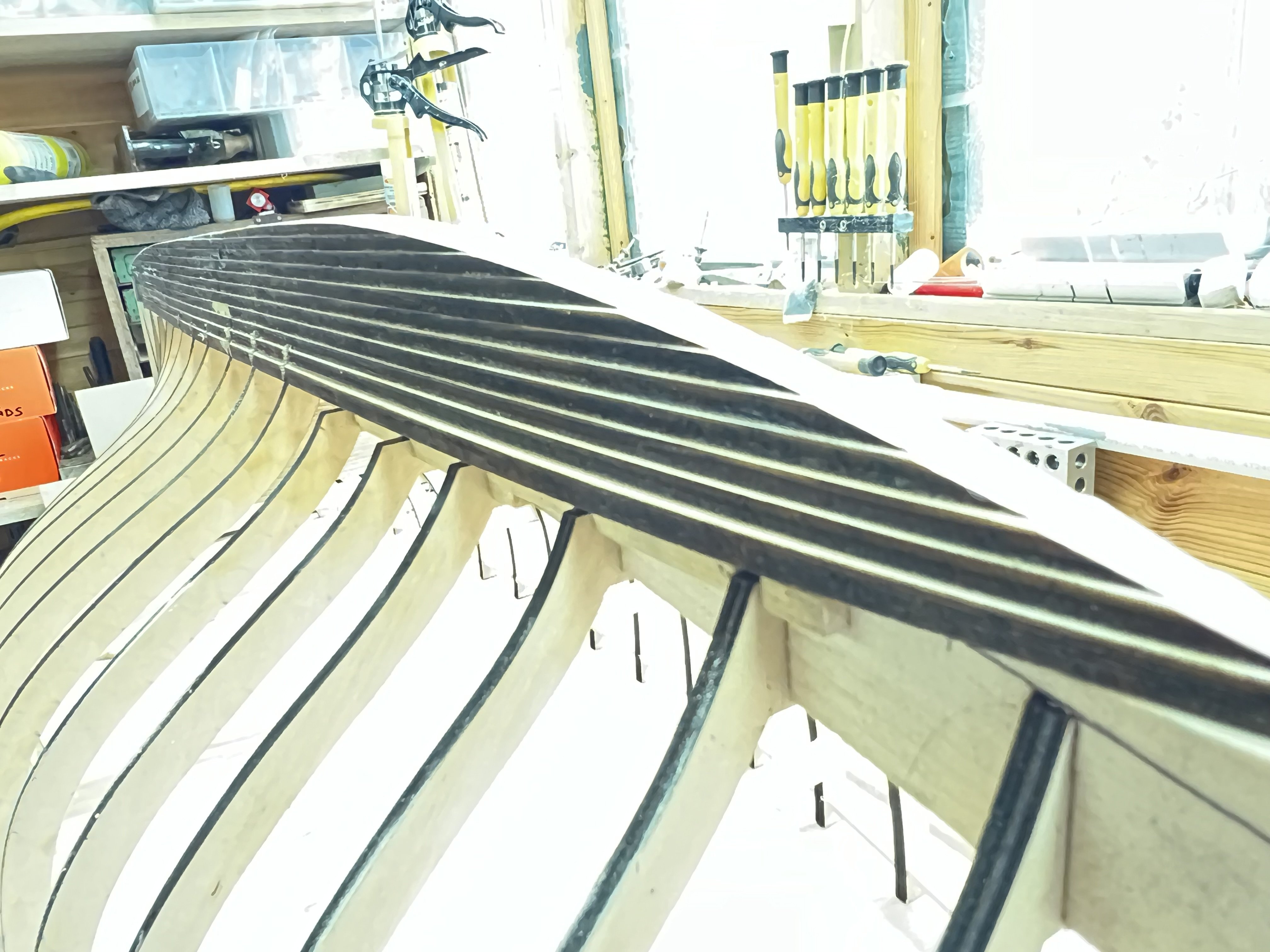
A little update after 4 hours of fairing. Using power tools and hand tools.

The Keel faired to the hull. Still needs finishing before coating.

Cutwater fairing is going well still needs finishing with hand tools and finer grit.

another view if the Cutwater.

Sternpost fairing going well. As above need finishing.
More sanding before coating and recoating a few times.
Regards AntonyUK.
-
Good Afternoon John.
Yes a do have and used a dust mask for the cutting and sanding as the dust is very fine and could do a lot of damage in the lungs.
Thanks for the heads up and GOOD advice.
AntonyUK.
- druxey and Keith Black
-
2
-
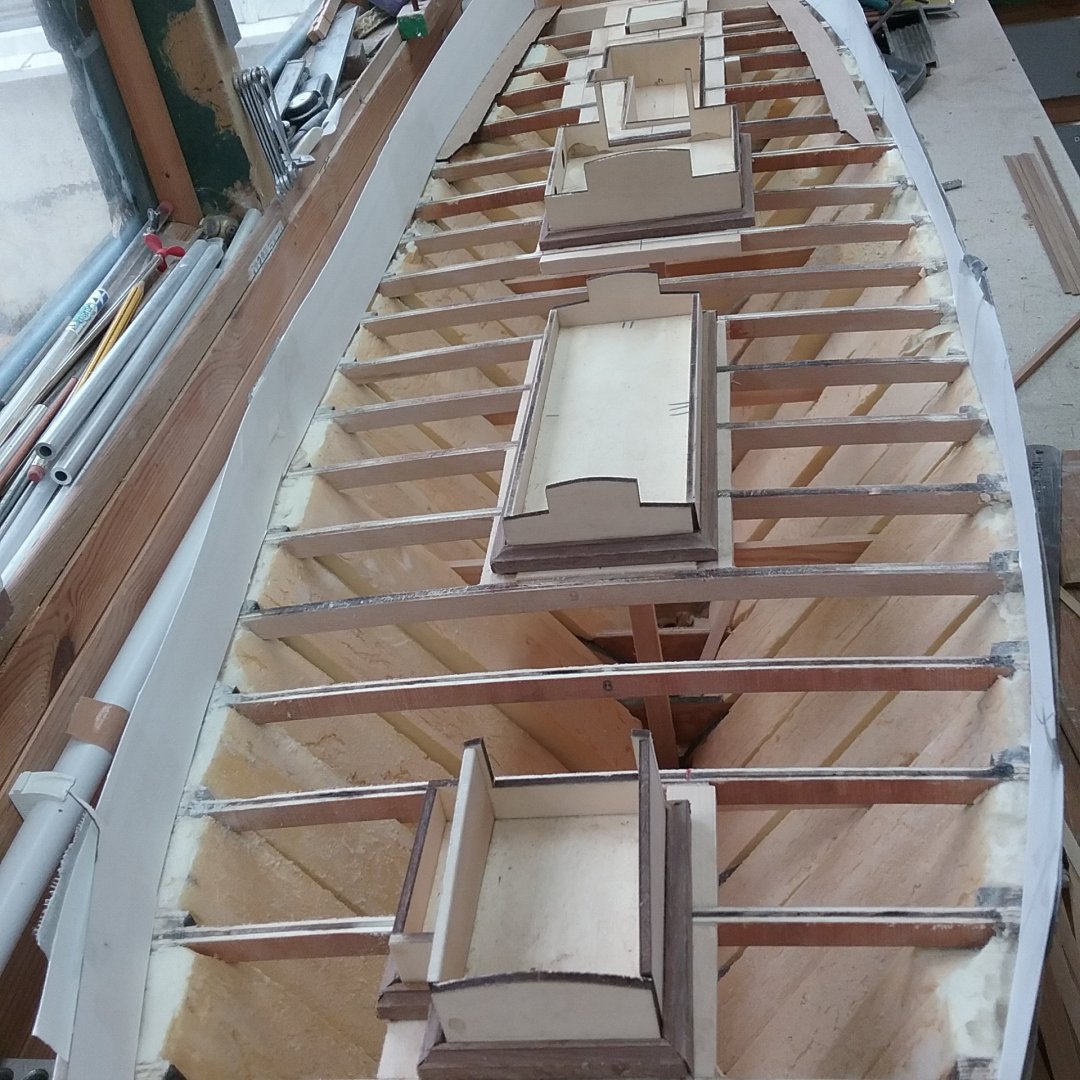
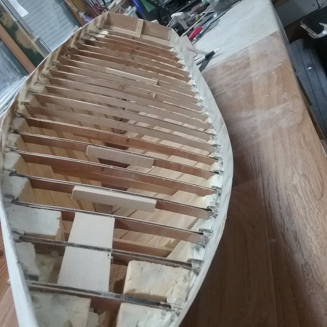
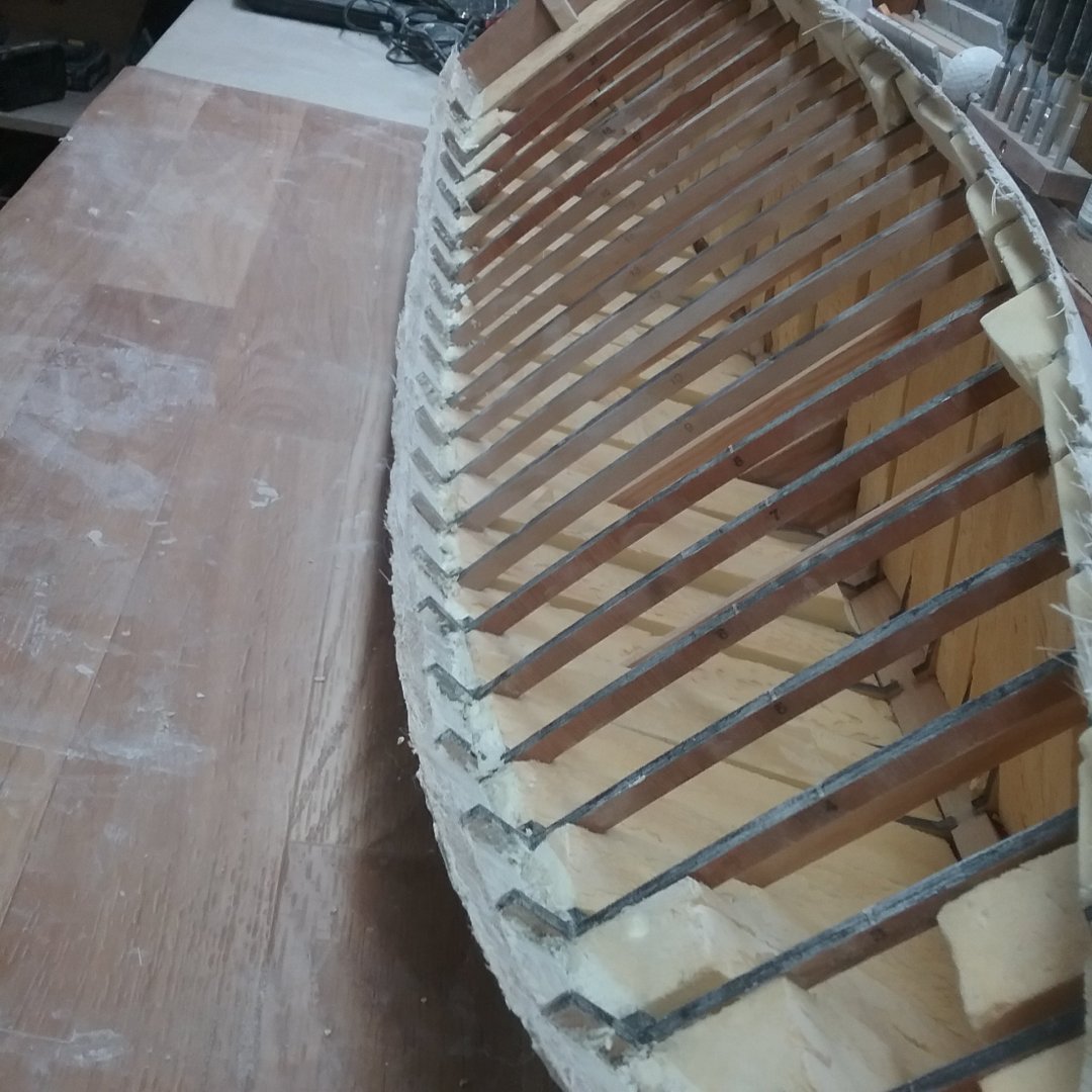
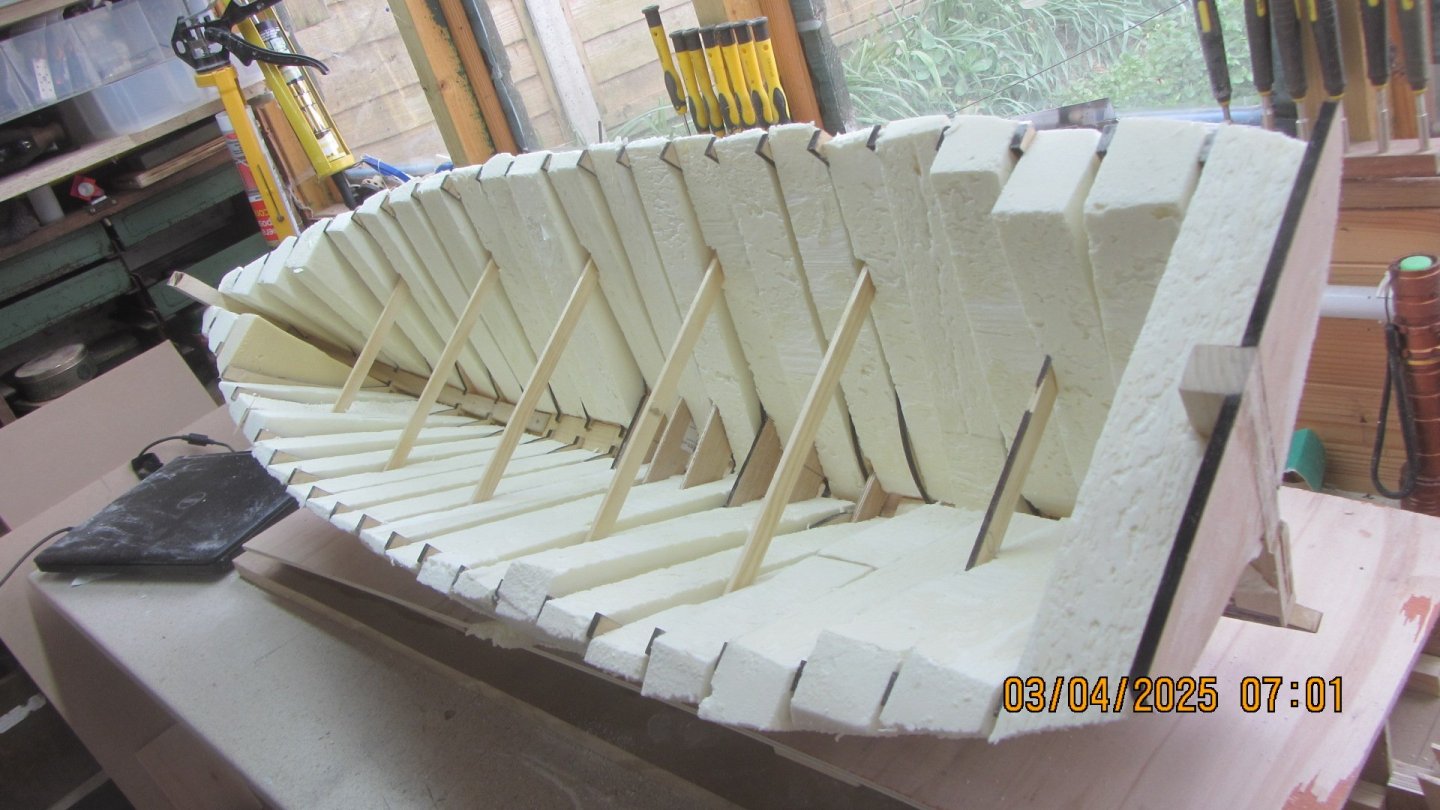
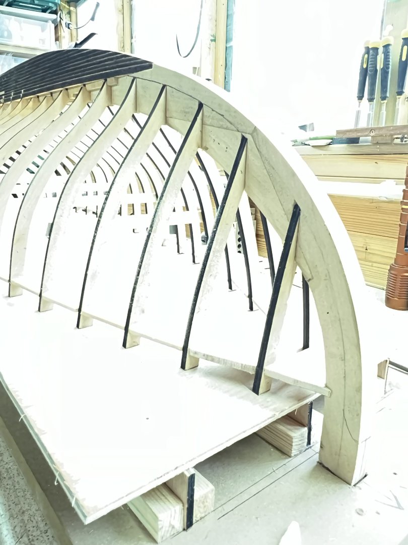
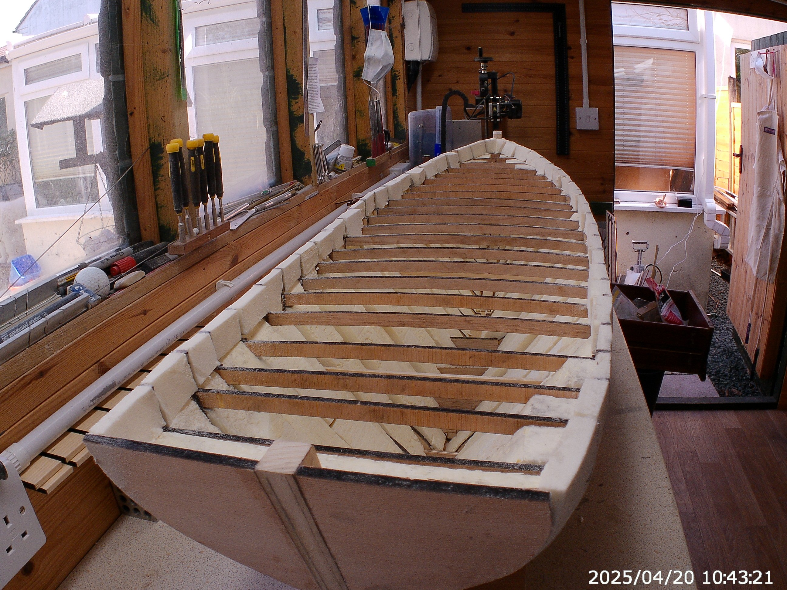
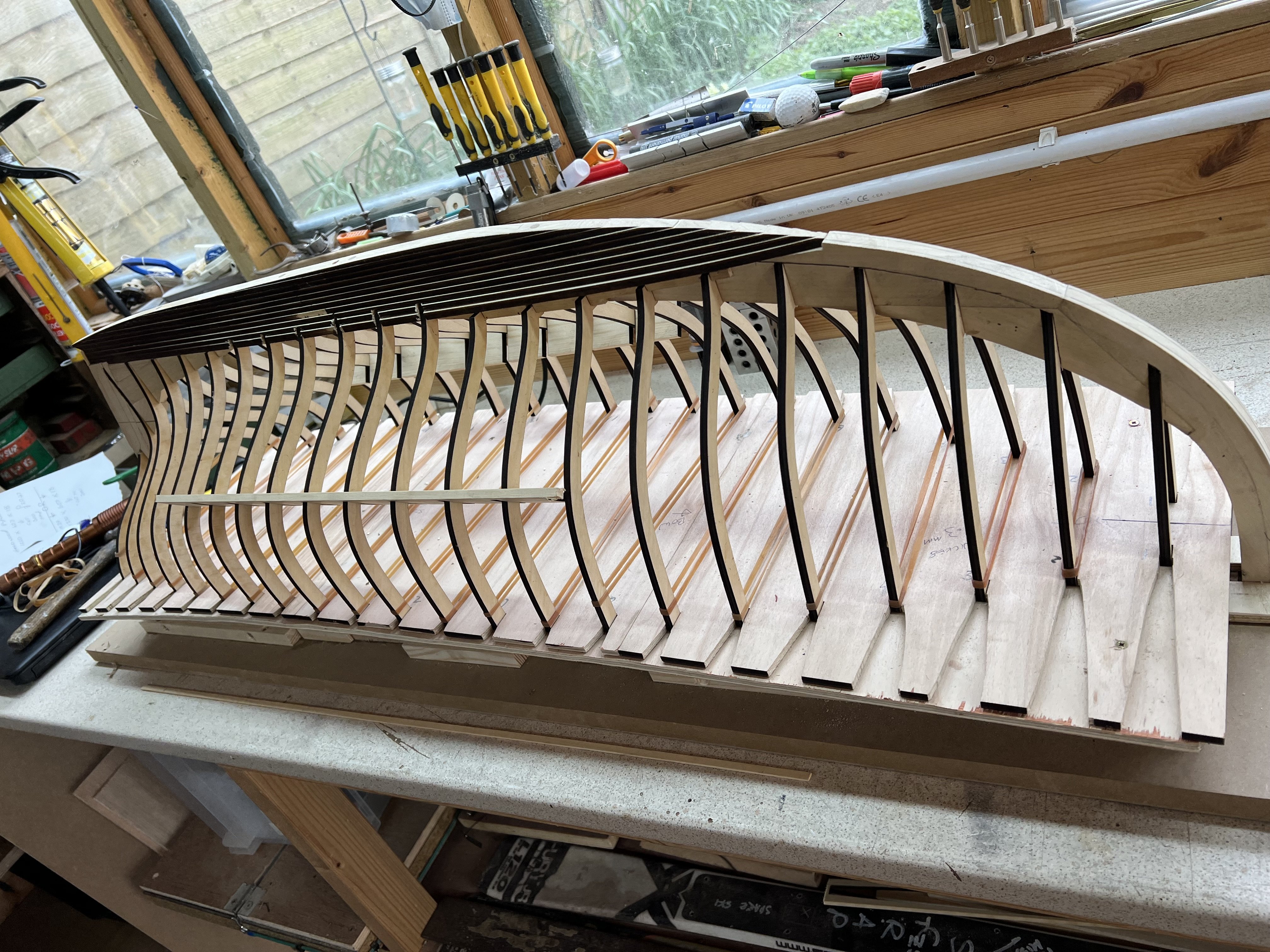
A little update.
The Polyisocyanurate boards were cut down into strips that are a tight fit between the frames. over size as its easy to sand to a good fit with sandpaper.
Used Everbuild 502 wood adhesive to glue the foam in place.
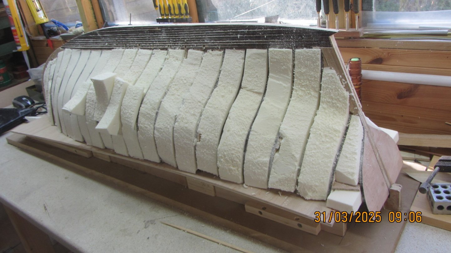
The extra bits were flats so a little scraps are applied to fill the spaces.
The interior of the hull looks like its scrap but this will be cleaned up after fibre glassing.
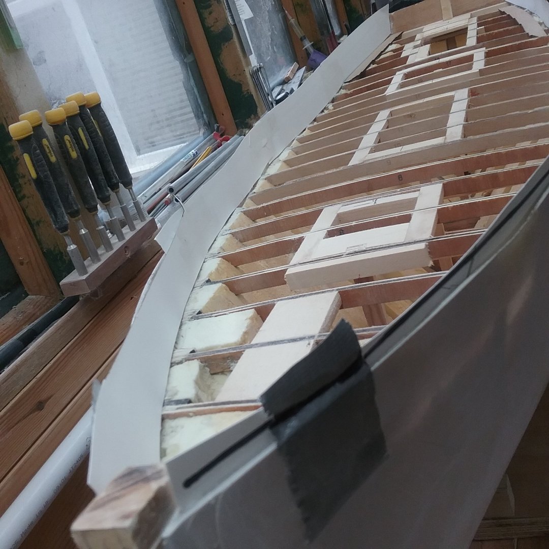
Did a little trimming today to get rid of most of the excess foam. by trimming with a hacksaw blade and then sanding with flat board with sandpaper. and the concave parts I used a spray can with sandpaper wrapped around it to get the contours right.
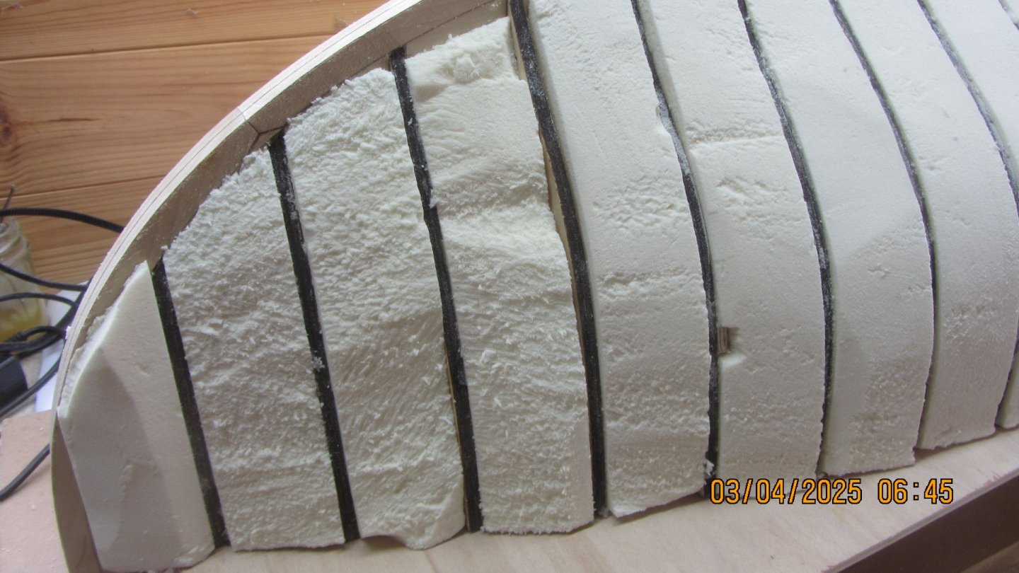
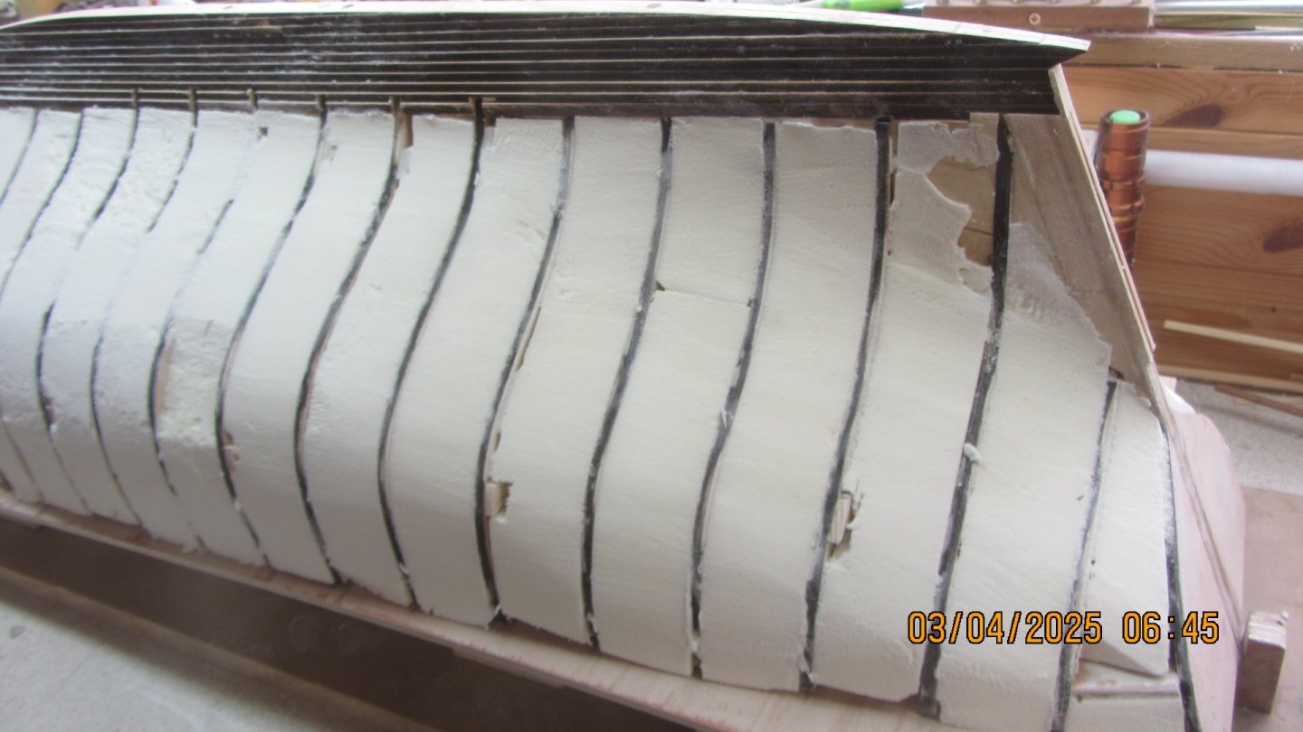
The photo above is the first level of sanding. will sand down till the charcoal from laser cutting is removed from top of frames. And yes this if a very dusty process and the correct type of raspatory mask and eye protection were used.
I estimate the sanding will take me a few days as its easy to work with but I want to get it as close as possible to perfect before continuing with the next phase.
Thanks for looking in.
Regards AntonyUK.
- Scott Crouse, Keith Black, KeithAug and 4 others
-
7
-
Hi Keith. yes I have seen them. poor health ETC. Shame as I liked the Little pancho and the Forklift.
I have never Not finished a model As yet... but Age and health .. Who can tell.
Regards AntonyUK.
- Keith Black and druxey
-
2
-
Good evening.
Greg. Im'e sure he would if he was still in his workshop. I liked the choice of timbers he selected for the rebuild.
Keith. Pancho has been a part of Tally Ho from the beginning. along with the hens and the dog. Always nice to see.
Jim, Jerome. I like the lines of the boat and its a easy to model as the drawing have all the information needed.
Just sourcing the Polyisocyanurate boards. local supplier calls it Celotex. Must be this type of foam so it can be laminated with any resin without dissolving.
Then on with the fill between the frames.
Thanks for looking.
- Keith Black, dvm27 and druxey
-
3
-
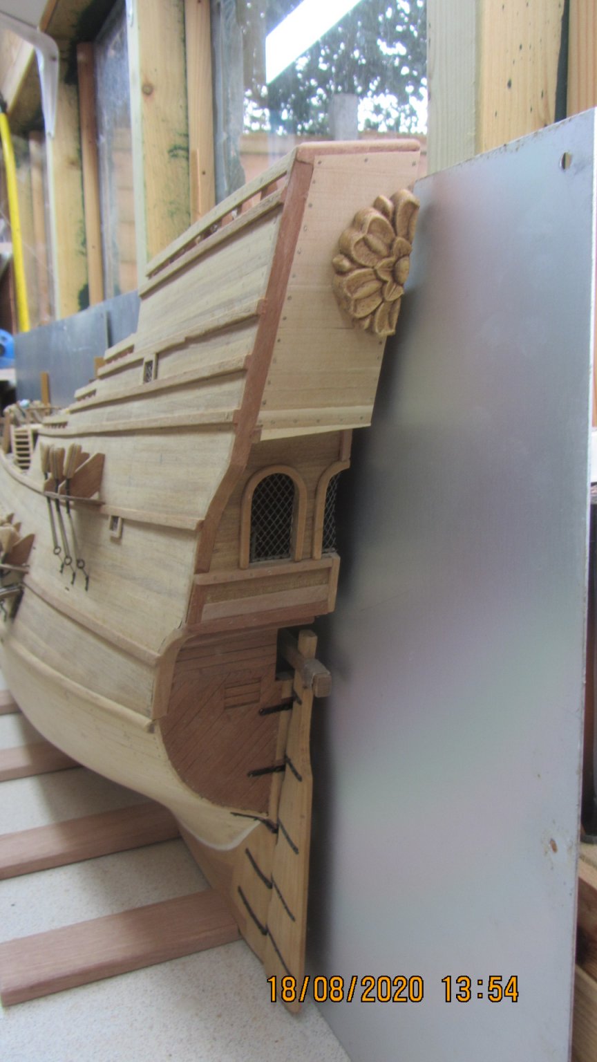
The boat Tally Ho.
I got interested in this cutter from a YouTube series by Leo.
https://www.youtube.com/@SampsonBoatCo/videos
Followed the build all the way through. Leo is a Boat builder and sailor. (His words)
Started on this boat in August 2024 by ordering a set of plans from the Albert Strange Trust https://albertstrange.org/
I decided that the model should be :- 1000mm at the waterline and 1173 from Stem to Sternpost and a 287 Beam.
I used Fusion360 (Home hobby version) to bring the 2D plans into 3D which took me till December.
My son purchased a Laser cutter for me as a Christmas present. 22 watts and a cutting bed area of 410X400.
Then it took me 2 months to learn how to use it and to set it up in my shed with a Ventilation extraction system.
The software I used was Shaper Origin Addon in Fusion. to export the .svg file to Inkscape. And then into LaserGRBL for the cutting interface to the Laser cutter.
The Stem Sternpost Deadwoods are 16.6 timber. They were marked by laser engraving a line onto the timbers and band sawing the parts out. They were finished to size using a Proxton mini mill to square and split the laser line.
The Bow and stern sections were assembled and checked and glued.
The Keel was made up by using a bread and butter construction method. The layers were cut on the laser using 4.2mm pine from my local DIY store. I had 4 dowel pin holes along the length of the keel to ensure the straight and true alignment.

Dry assembled and checked for length shape and alignment. All good so on with the gluing.
The frames were laser cut using 6mm laser ply. This was my first real cutting with the laser.
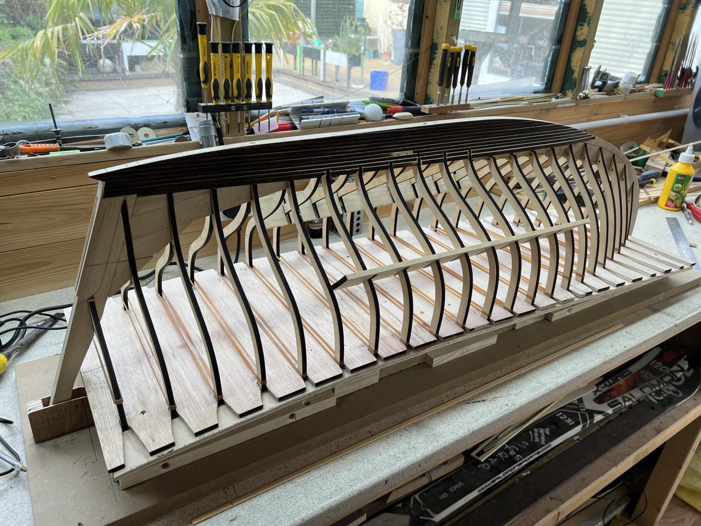
The Bow Stern and keel were glued and pined together. Wow this is going to be a BIG model.
I also designed a Jig to build the boat on fusion to help with the alignment.
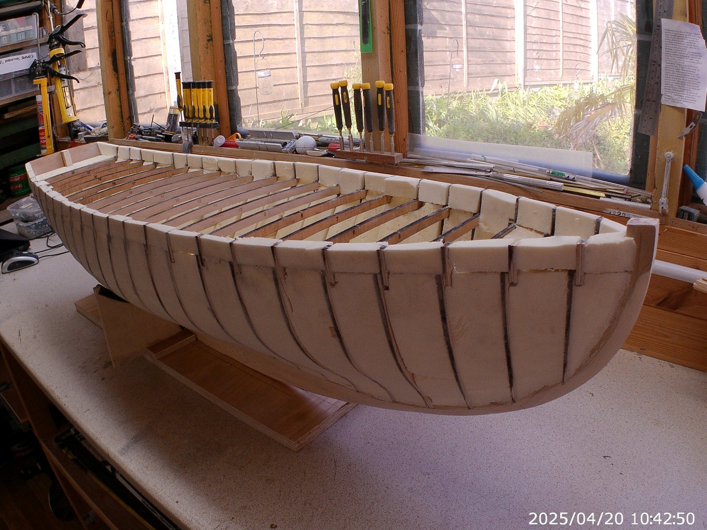
Building this boat inverted as it best for me. The keel and Stem and Stern post were added to the Jig then the frames were placed in place on the jig. Everything looked spot on so i glued them together.
Small bits if off cuts were added between the frames to maintain the correct frame spacing.
Now we are up to date with the build as it is now.

Next week.
Going to fill between the frames with 40mm insulation foam boards. This will provide me with something to fare the frames and to lay fibreglass onto.
Not done any fibre glassing before so ANY advice would be helpful.
Regards AntonyUK.
-
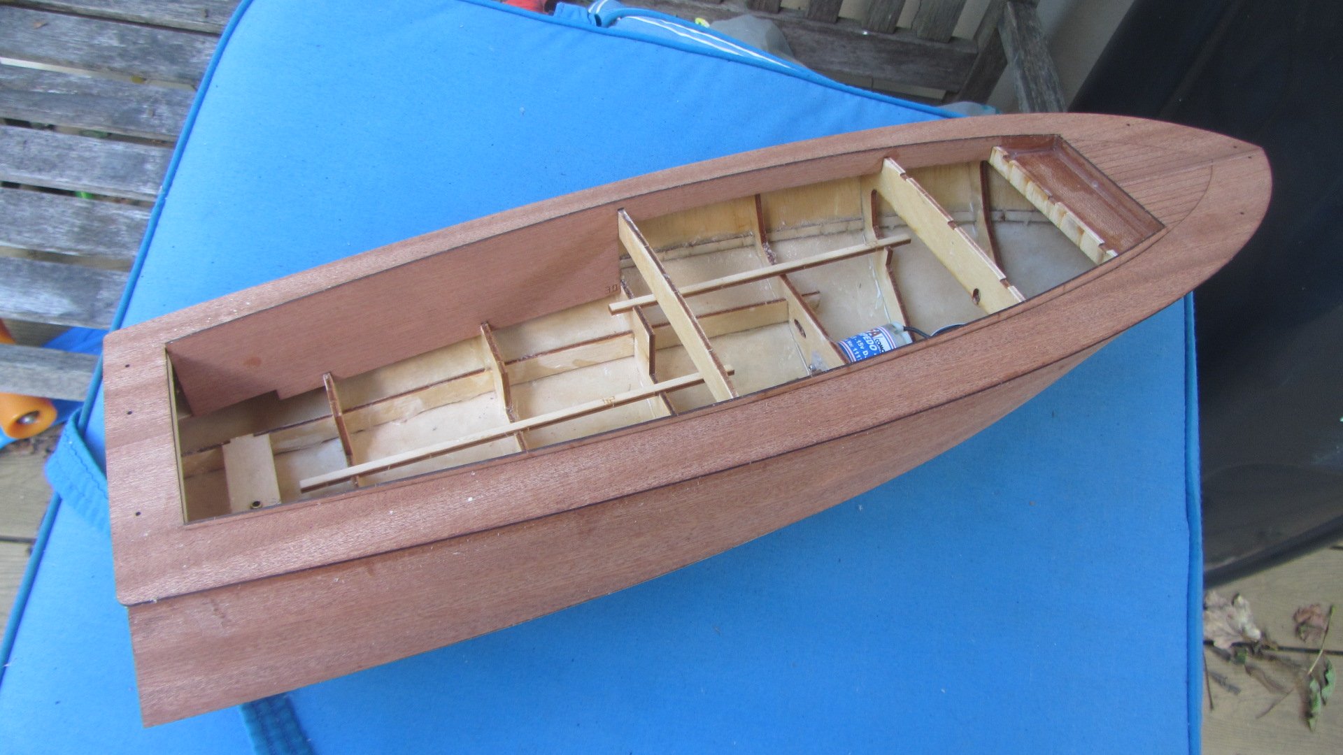
Time for a update. Most of the building has been completed and it now looks like a boat.
Grandson if now getting excited as it taking shape.

The thin strips are a little fragile on the joins. So I added some fillets to strengthen the joints.
Superstructure is now complete. Again a few scraps to the joints to reinforce the areas.
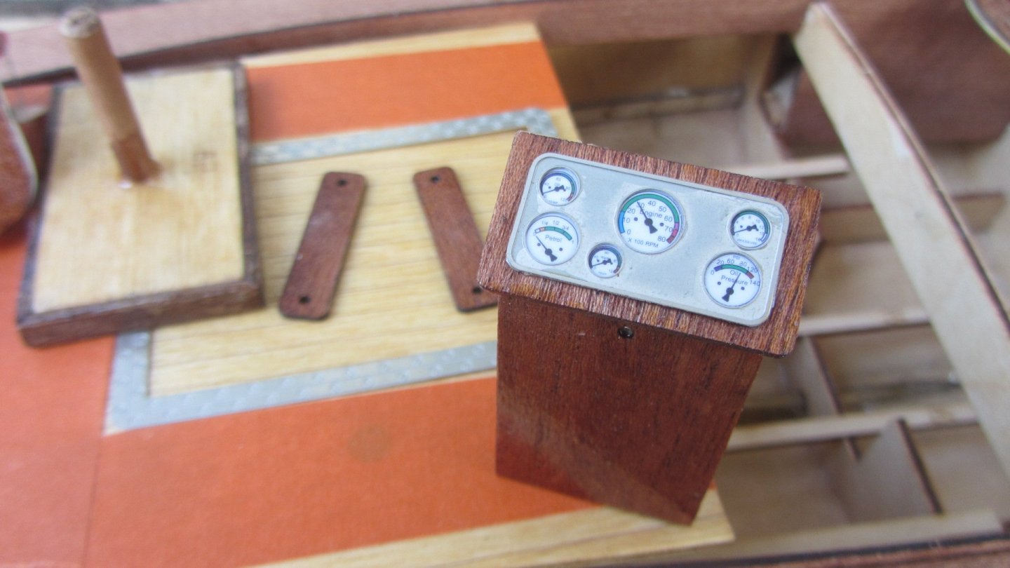
The console is as supplied with the kit. Nice. The gauges were printed on the coloured instruction manual. With a laser cut aluminium trim.
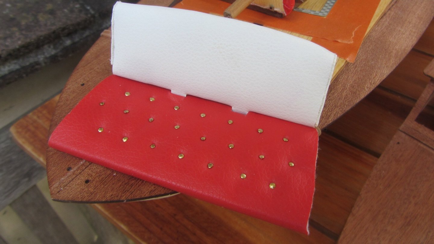
Seats make up using Red vinyl plastic simulated leather. The white was suppled with the kit. Red was a Sample from E-Bay 99p. Brass nails completes the look.

Sump deck getting ready to glue aluminium engine hatch in place.
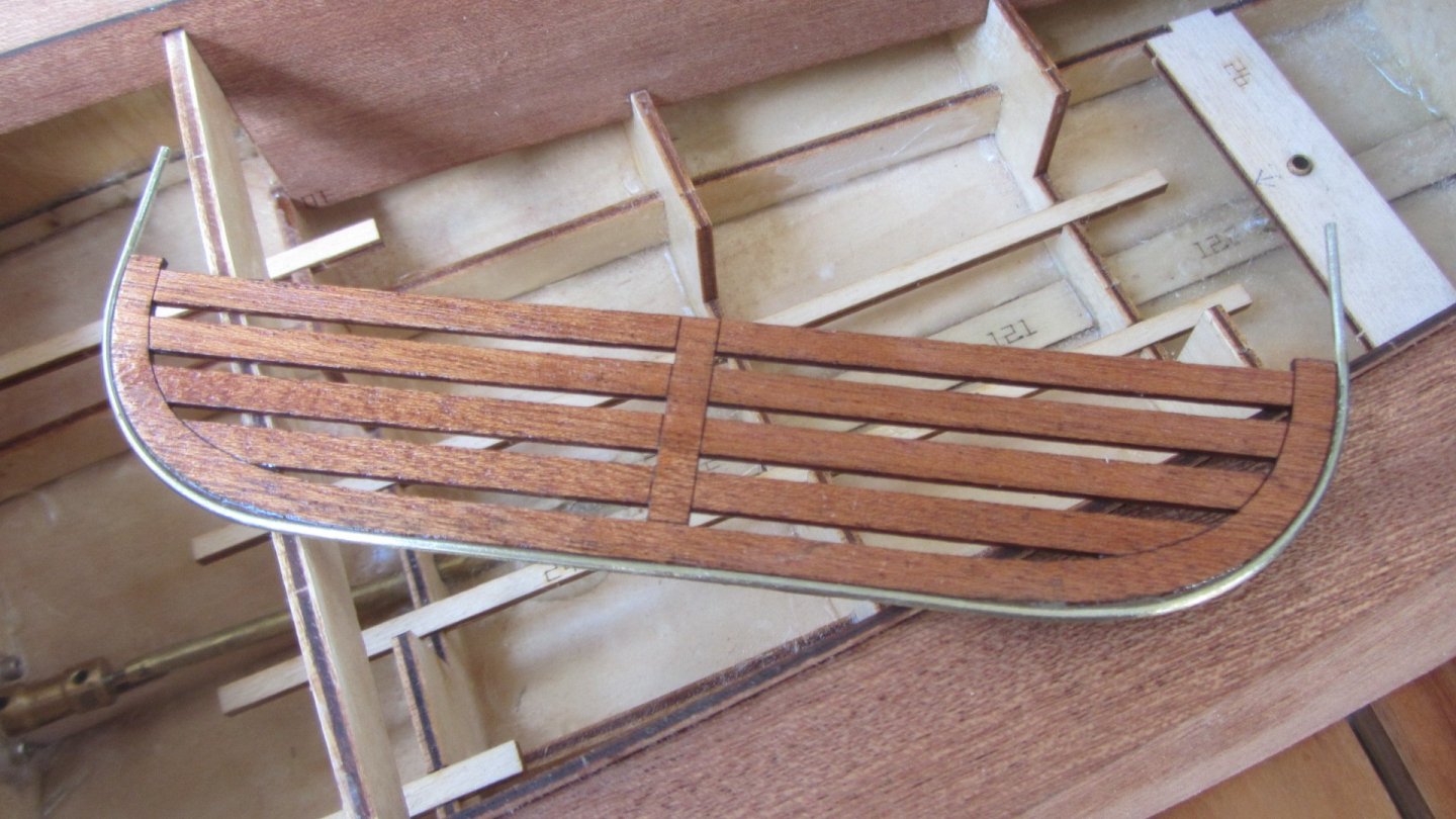
The platform on the stern turned out OK after the re bending of the wire.
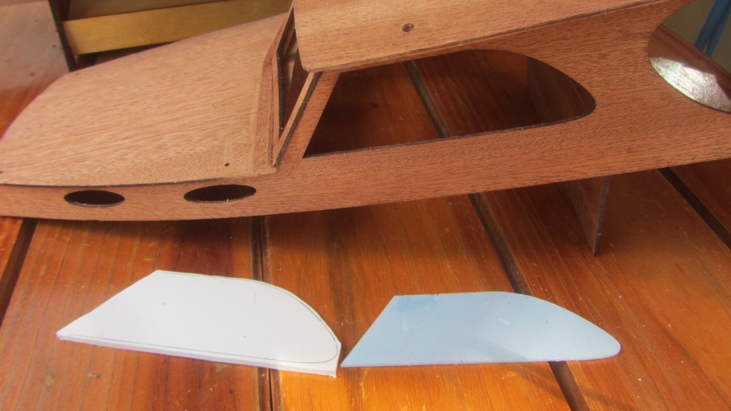
The windows. Instructions say to "glue the glazing panels to the inside of the cabin." Not possible as the panels were smaller than the cabin holes.
Purchased some 2mm polycarbonate and cut then out + 2mm bigger.
More varnishing this week and next week allowing time for it to dry first.
We are going to add lights to this model as I can teach him to solder and he would like the lights.
Then Radio and electrics insulation.
Thanks for looking.
- ccoyle, king derelict, mtaylor and 3 others
-
6
-
Hi Another update on the Build.
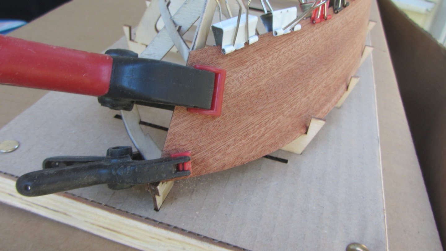
Deck is now on and fitted with a slight overhang all round, I will seal this and put a "L" shaped stringer to tidy up the edge.

Also the hatch sides were added which aligns the deck to the centre of the boat.
I added a little reinforcing to the Bow area inside the hatch area. I covered the inside with a fine glass fibre cloth weave and resin.
The hatch sides/cabin is put in place and glued only to the bulkhead/access door with a little piece of 3x3 to inside to reinforce the joint.
This fit is with No trimming. Quit impressive for a kit.
A jig I made up to hold the front cabin roof supports square while the grandson does the gluing. And yes I will use a little strip of cling film to stop the parts and jig from gluing together.
Its taking time as he stays with us one night a week. Never rush a nice thing...
Thanks for looking.
AntonyUK
- mtaylor and Kenneth Powell
-
2
-
Just a few more pictures of the build.
I am doing all the preparation work IE fairing and chamfering the edges as per instructions. And the grandson is doing all the gluing.
Did not follow the instructions here as I wanted to make it easer fore the grandson to do the gluing.

I like this idea of holding the top of the sides with lugs designed into the kit.
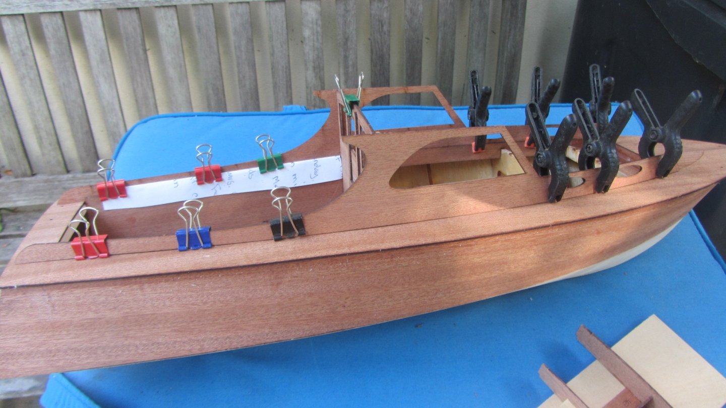
That's the hull skins on and building lugs removed.
So far no modifications have been make to the kit design.
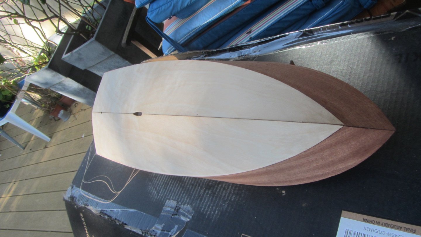
Hull bottom view.
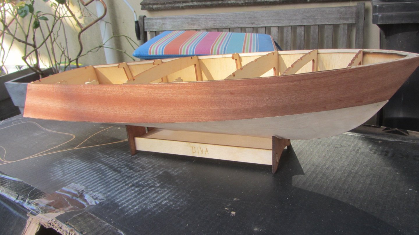
Side View with stand. I have put a sheet of wood inside the stand as the prop shaft cut out is a very weak area.
I am planning to coat the interior with a lightweight cloth and resin. To waterproof and strength reasons. I foresee many collisions in the learning process.
Regards Antony.
-
Hello again. Been a while since I posted on MSW.
I am introducing my grandson into the model boat building. He is 7 years.
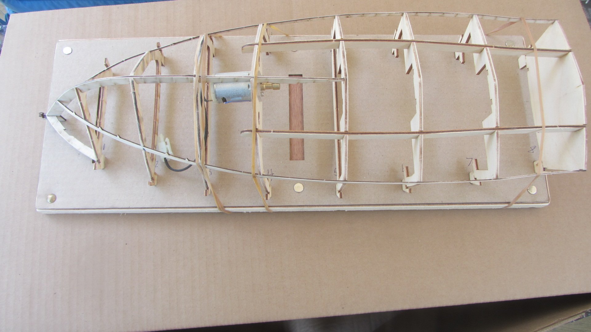
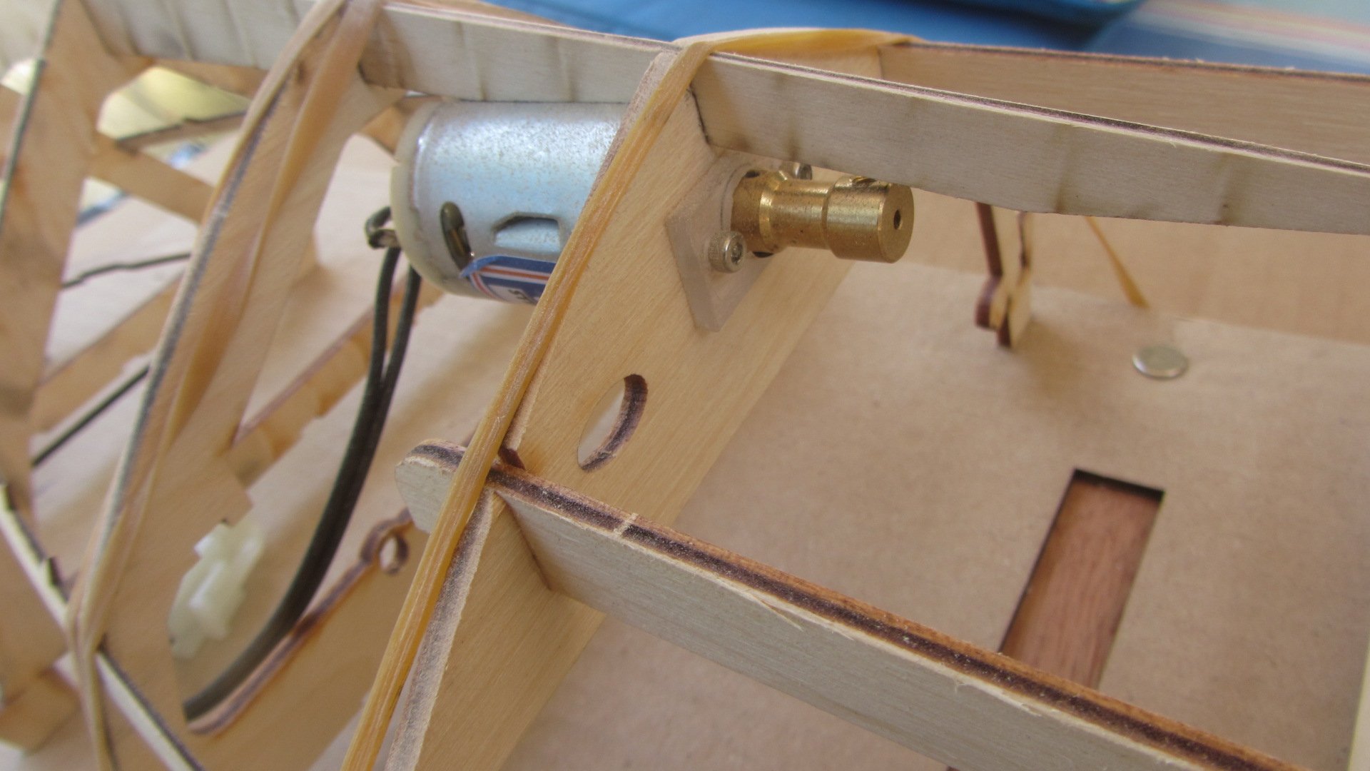
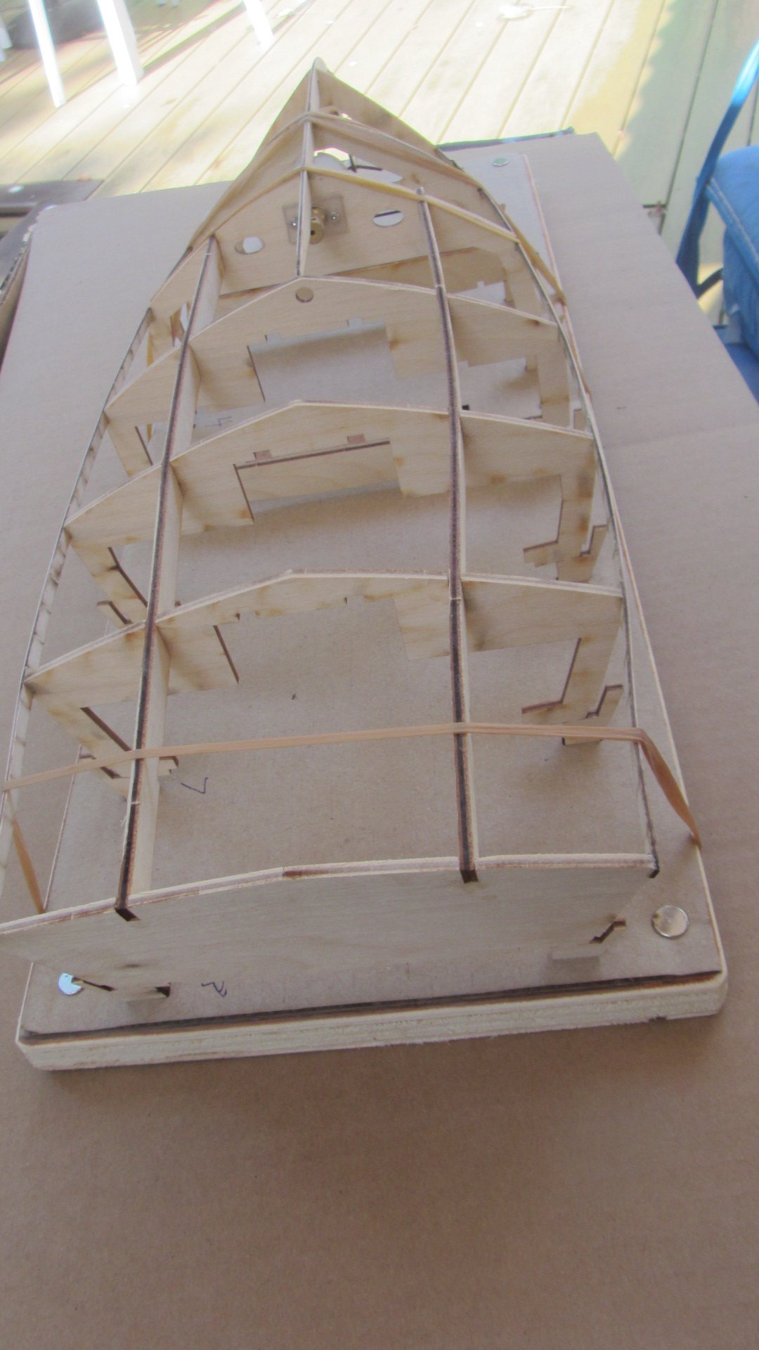
The model I have chosen for him is the Aero-naut's Diva. Its a nice size and it a functional boat IE with Motor and Radio control.
Opening the Box and the first thing I noticed was the two manuals. One with a lot of illustrations and text in German. and the other is in English. (which is quite good).
I have already started building so I will start with the minor things I did not like. The shaft tube is 5mm dia that's OK, But the shaft is steel and it just push fits into the plastic propeller.(Not good)
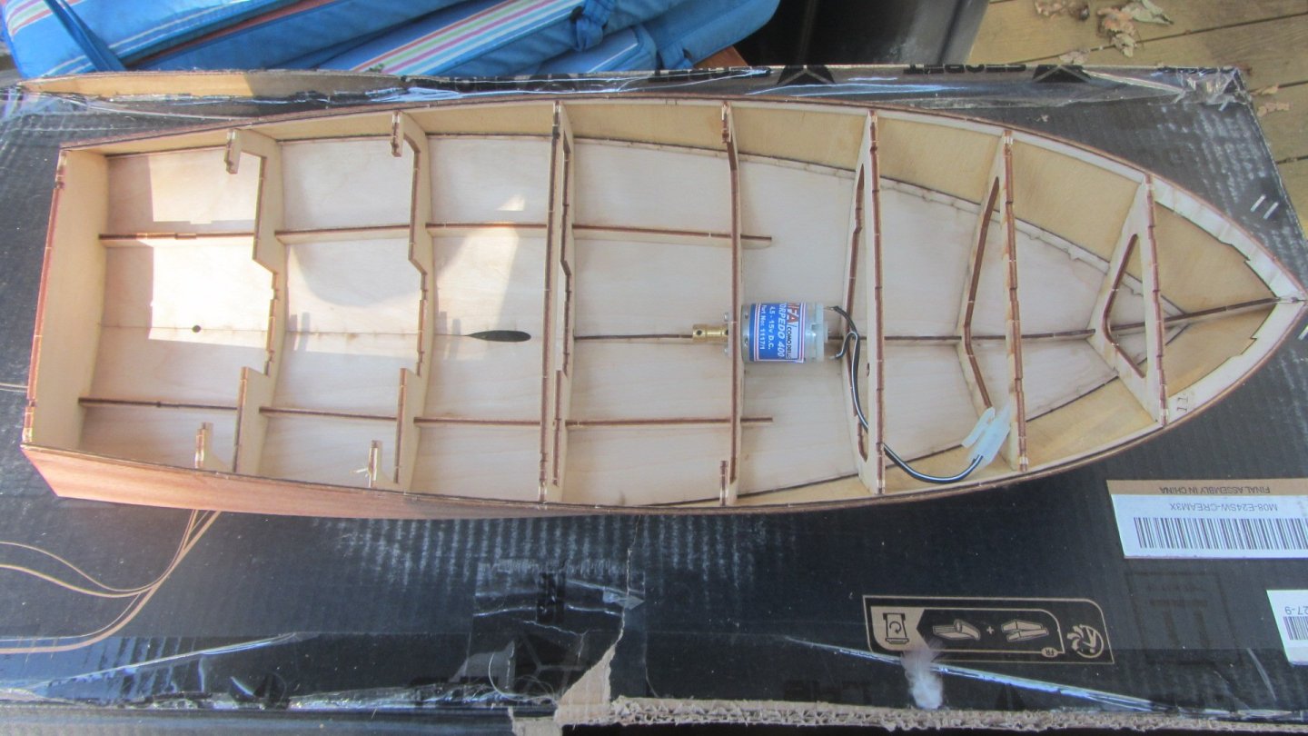
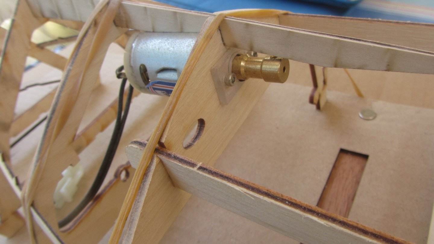
The motor I am using is a MFI Torpedo 400 2.5v to 12v. The coupling is a rigid shaft coupling.
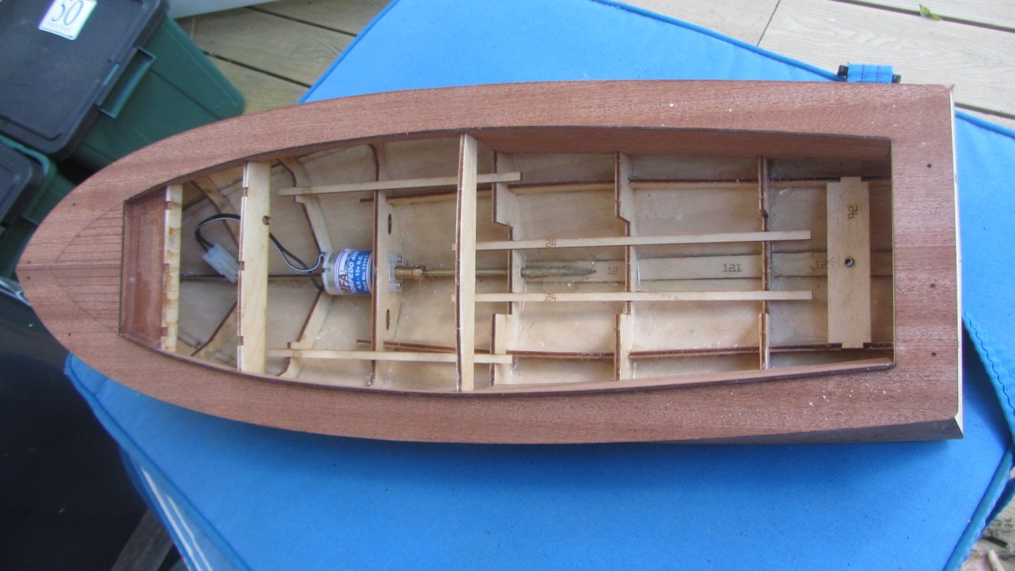
Now to the Kit.
The entire kit is first class with laser cutting at its best.
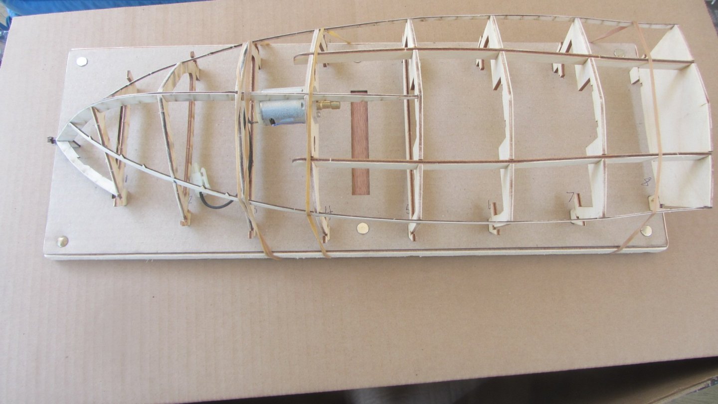
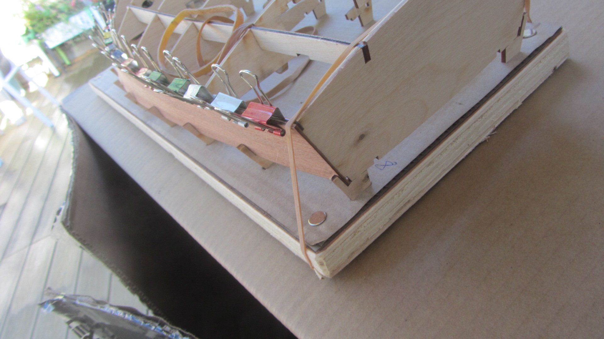
The kit has a cardboard base jig with slots for the tops of the frames to slot into. This was die cut. This was mounted on a scrap piece of 18mm plywood.
Started placing the frames into the correct positions and everything fitted with any modifications.
I added the motor at this stage as it was easer for him to put the M2.5mm screws through the frame into the motor. I also added a small plate to reinforce the frame made from polycarbonate.
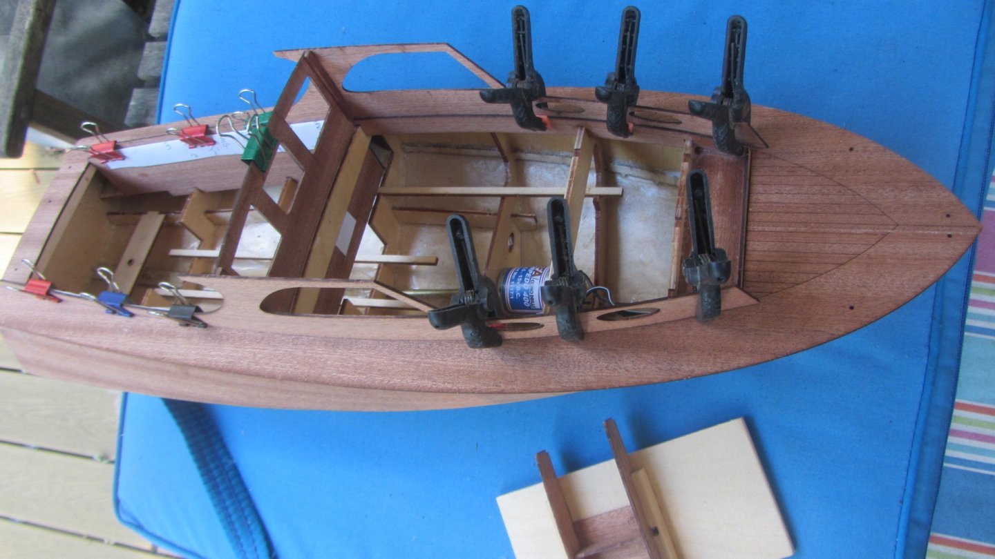
With the dry fitting done it was time to do the gluing of the body together. This went well and was held in place by elastic bands until dry.
Then we added the chine stringers. These were laser cut and in the correct shape. No trimming only at the bow area were the two chine rail meet.(slight chamfer) Again elastic bands were used to hold this in the correct position until dry.
The frames were faired to shape with a small sanding block. and the sides of the boat were given a little pre bending to make it easer to fit then to the boat.
That's it so far. Now for the photos.
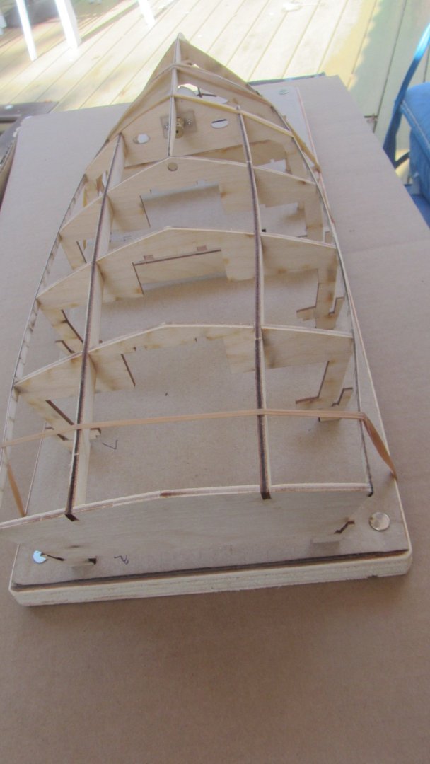
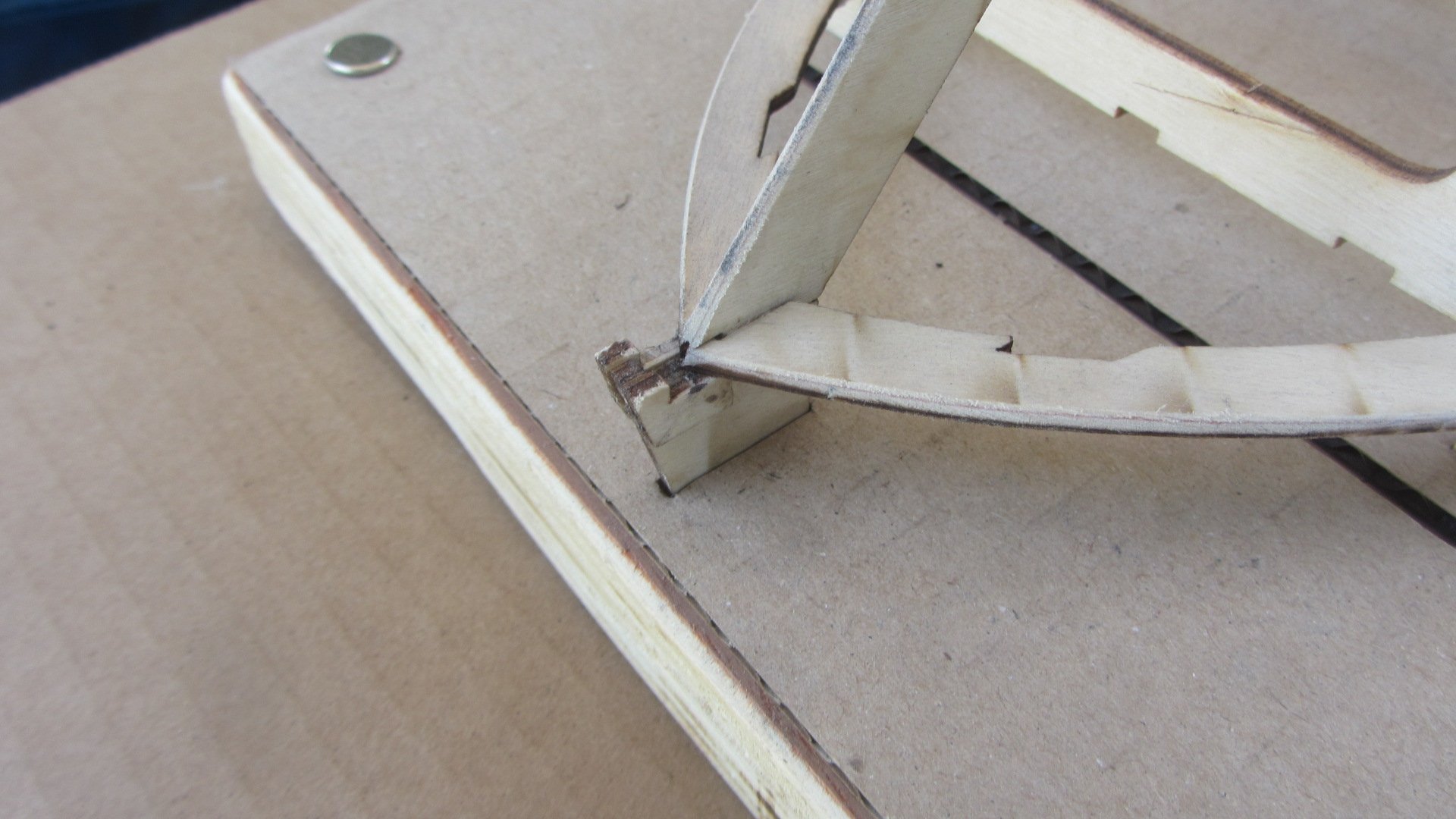
Image 1 is the bow and there are two very small to add to the keel here. They need very precise positioning or the sides/skins will not fit.
Image 2 is general side view.
Image 3 is Motor mounting mode.
Image 4 is general rear view.

-
Hi.
Well its a nice conclusion to the build.
Today the Model has been collected after waiting some 18 months for the Covid to calm down.
The nice thing is my work area is free again and its time to start researching something else to build.
A BIG thanks to all for your support and Comments.
Regards Antony.
-
Hi.
I also have purchased a 3D Printer (Elegoo Mars pro. )
I have used the printer for Model making components (Not ship).
Hero Forge is by far the best Figurine shop I have seen. So many choices of kit. clothing. posture. and the list is endless.
With the Figurine's available I will be putting some on my Ships as well. And being scalable they will adapt to any model I build.
Regards Antony.
- Old Collingwood, Egilman, mtaylor and 3 others
-
6
-
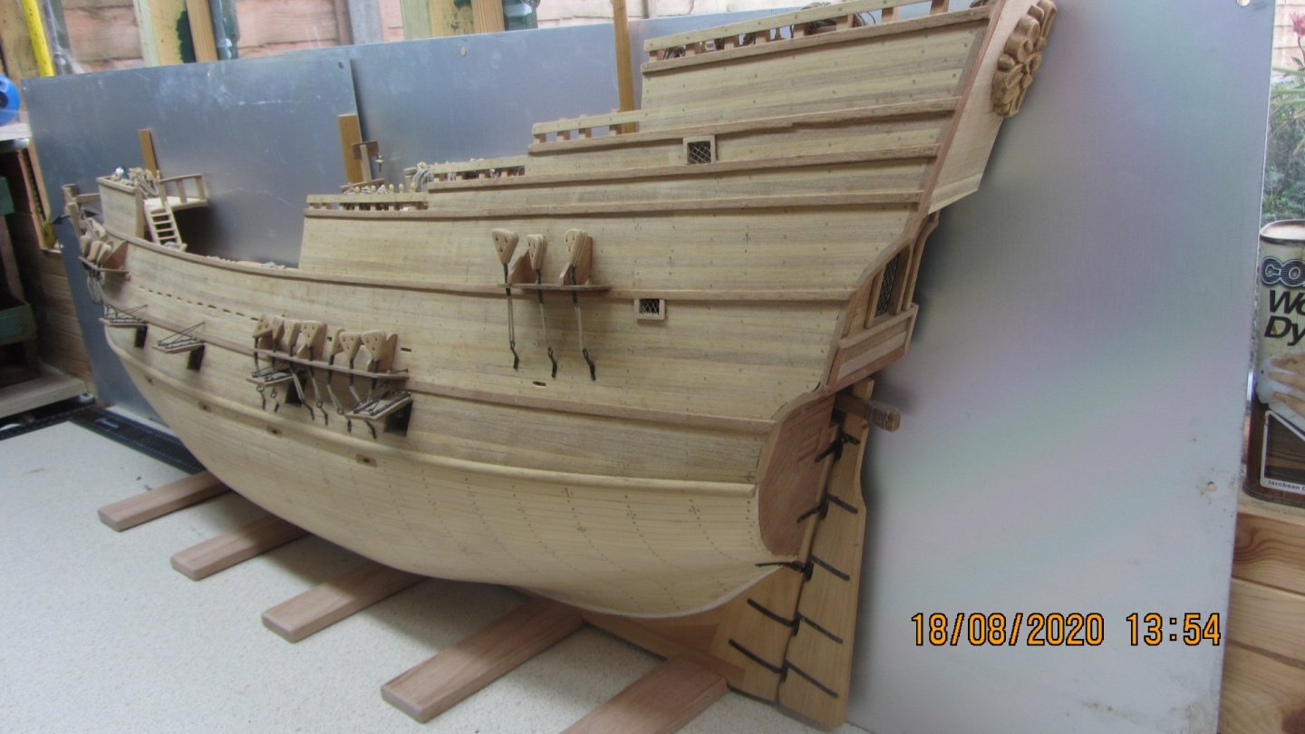
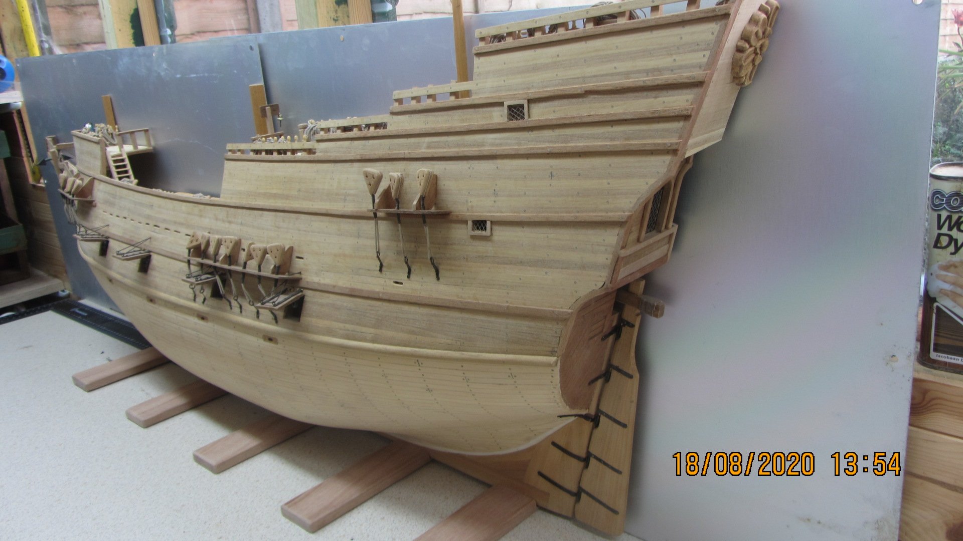
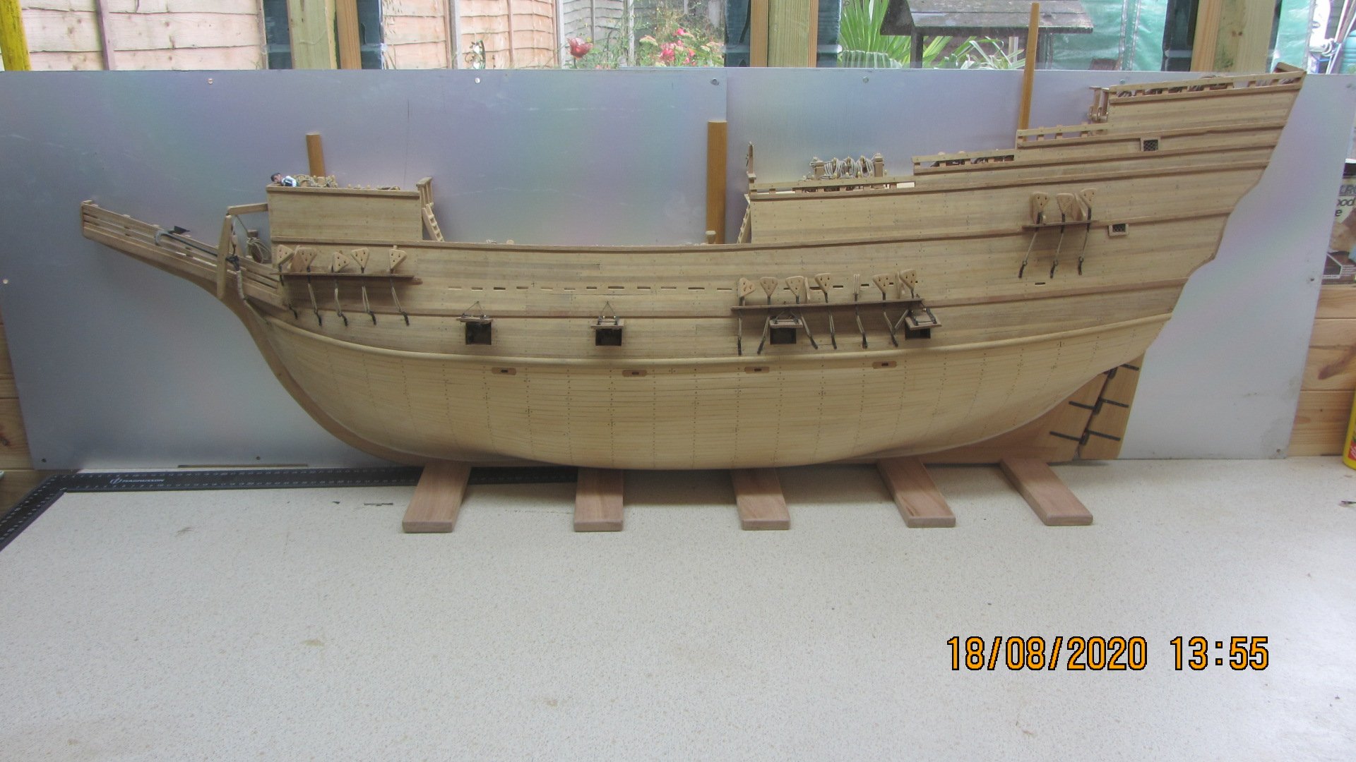
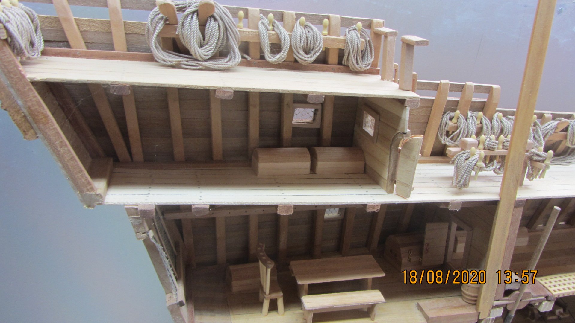
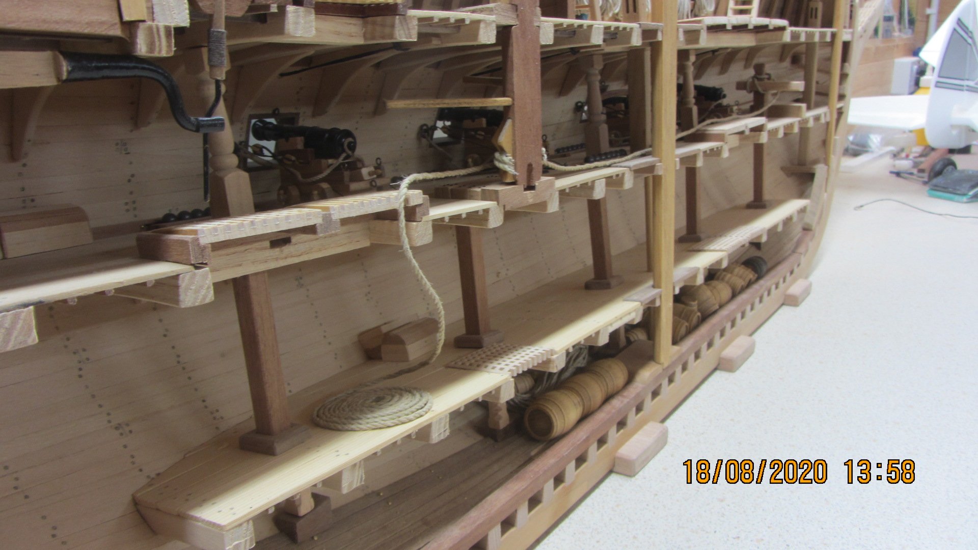
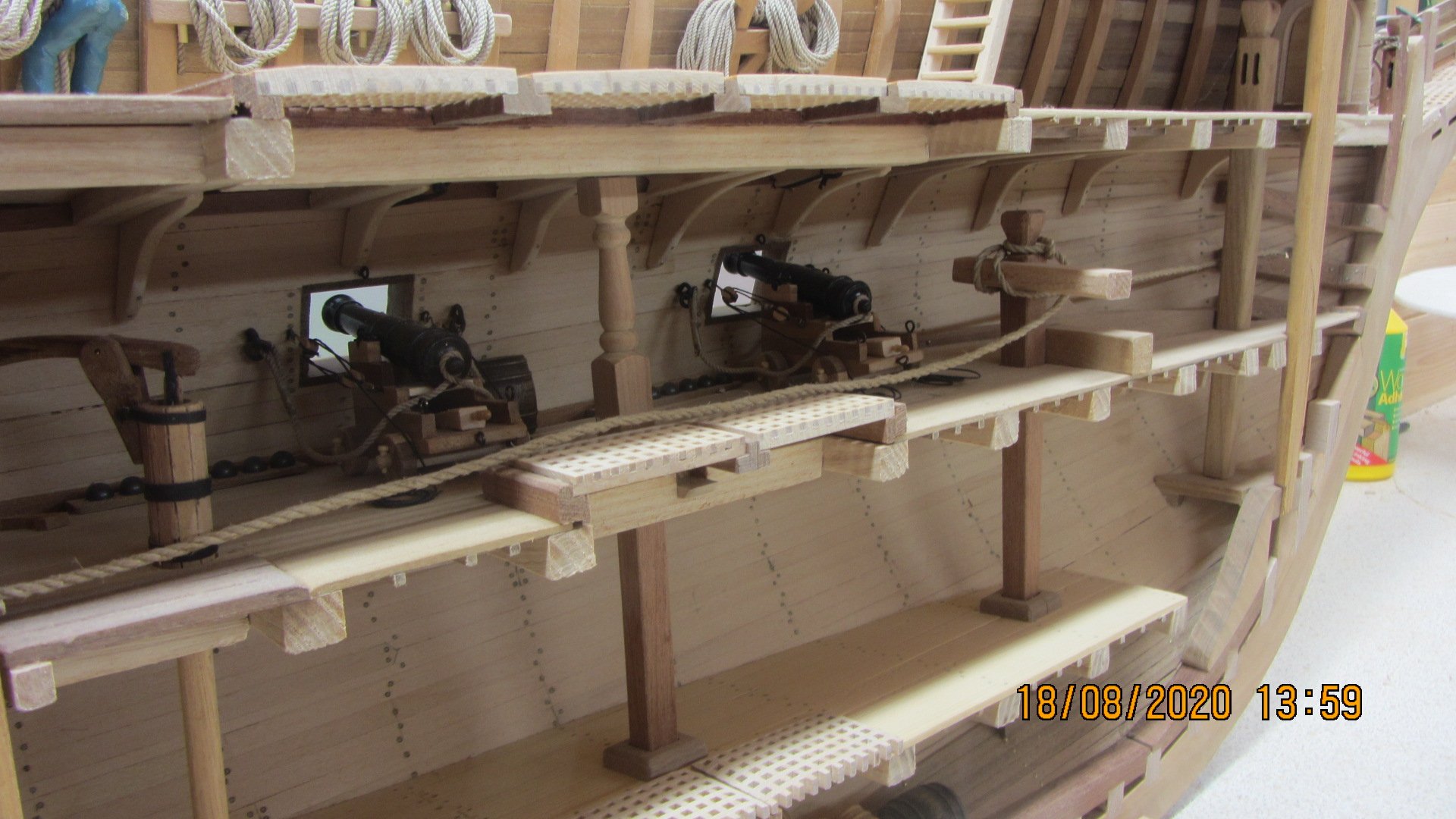
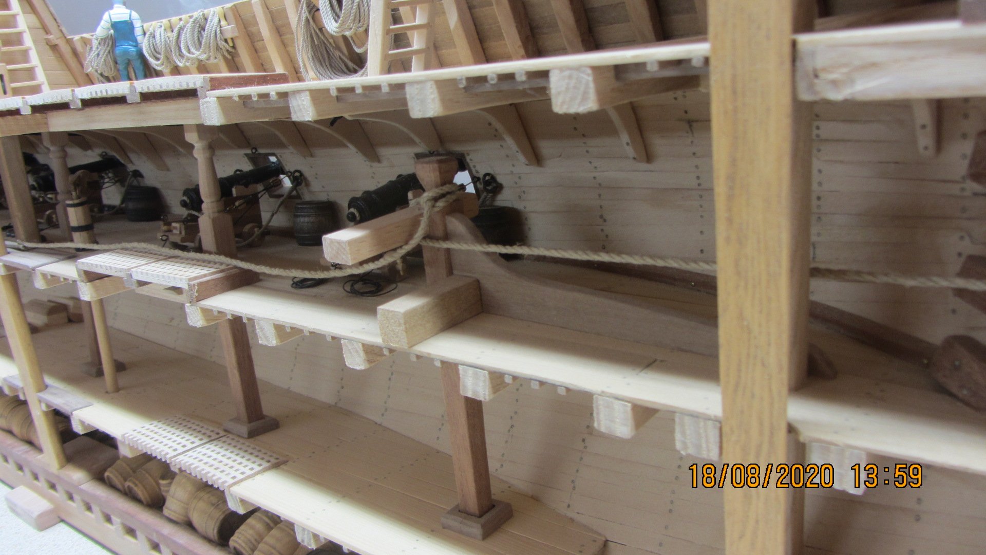
Hi and thank you all for your reply's.
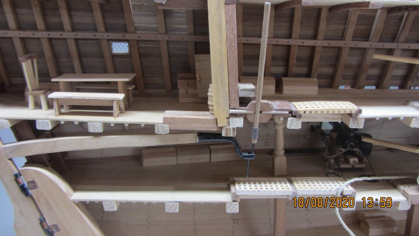
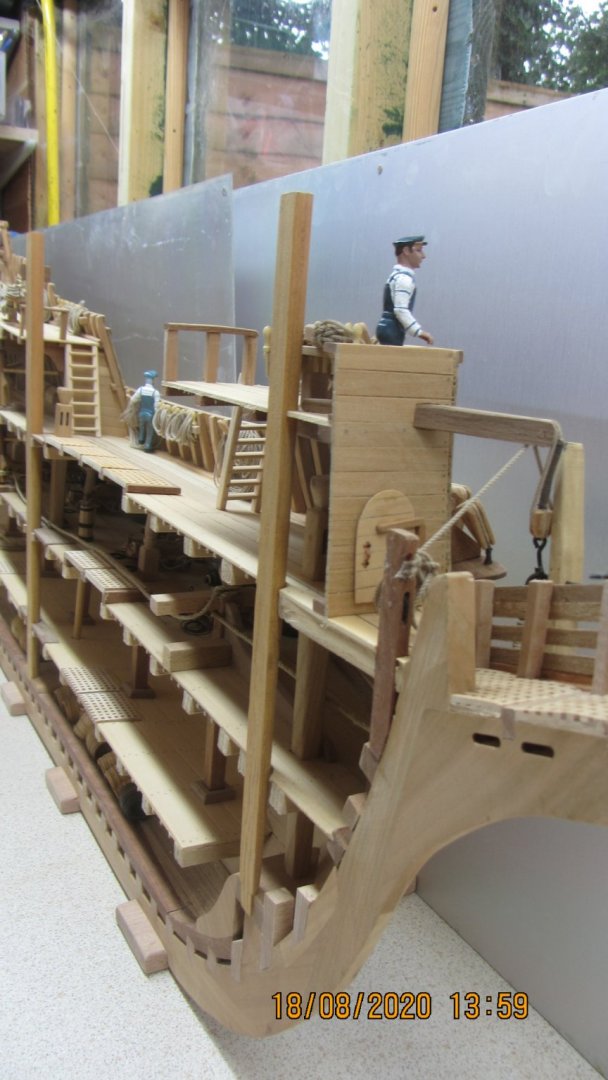
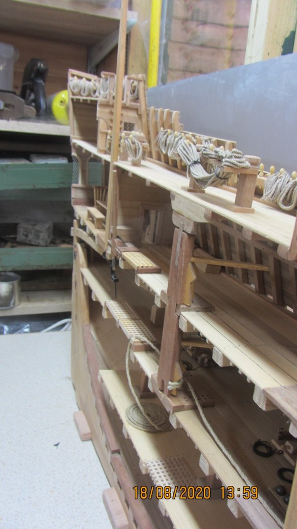
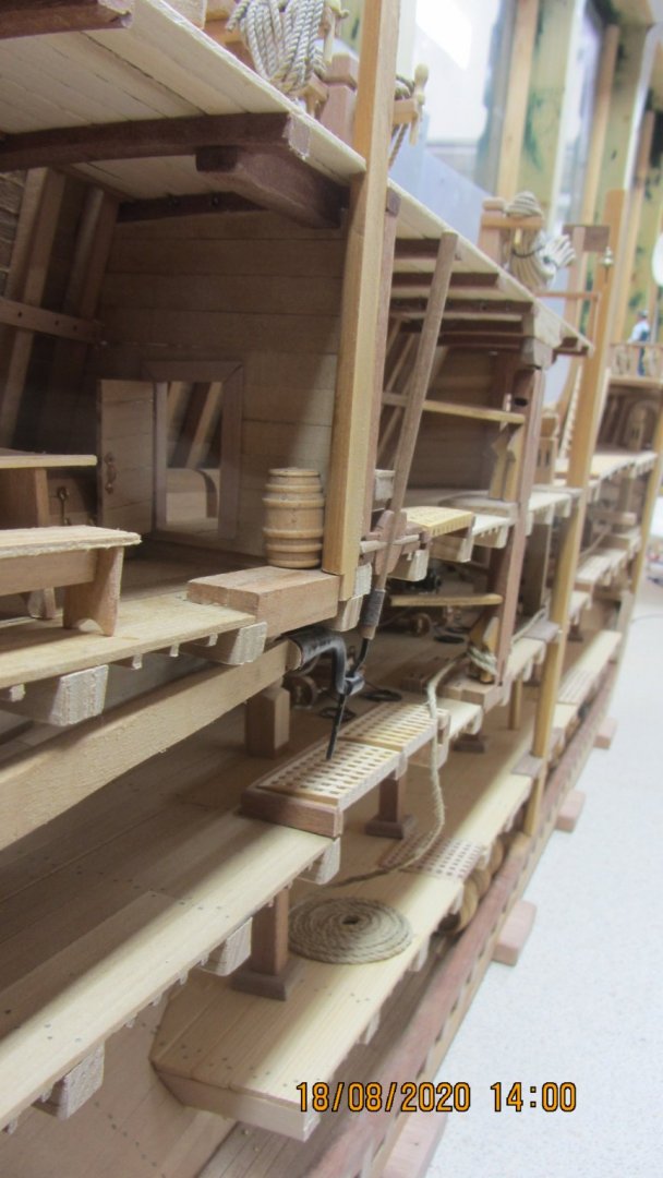
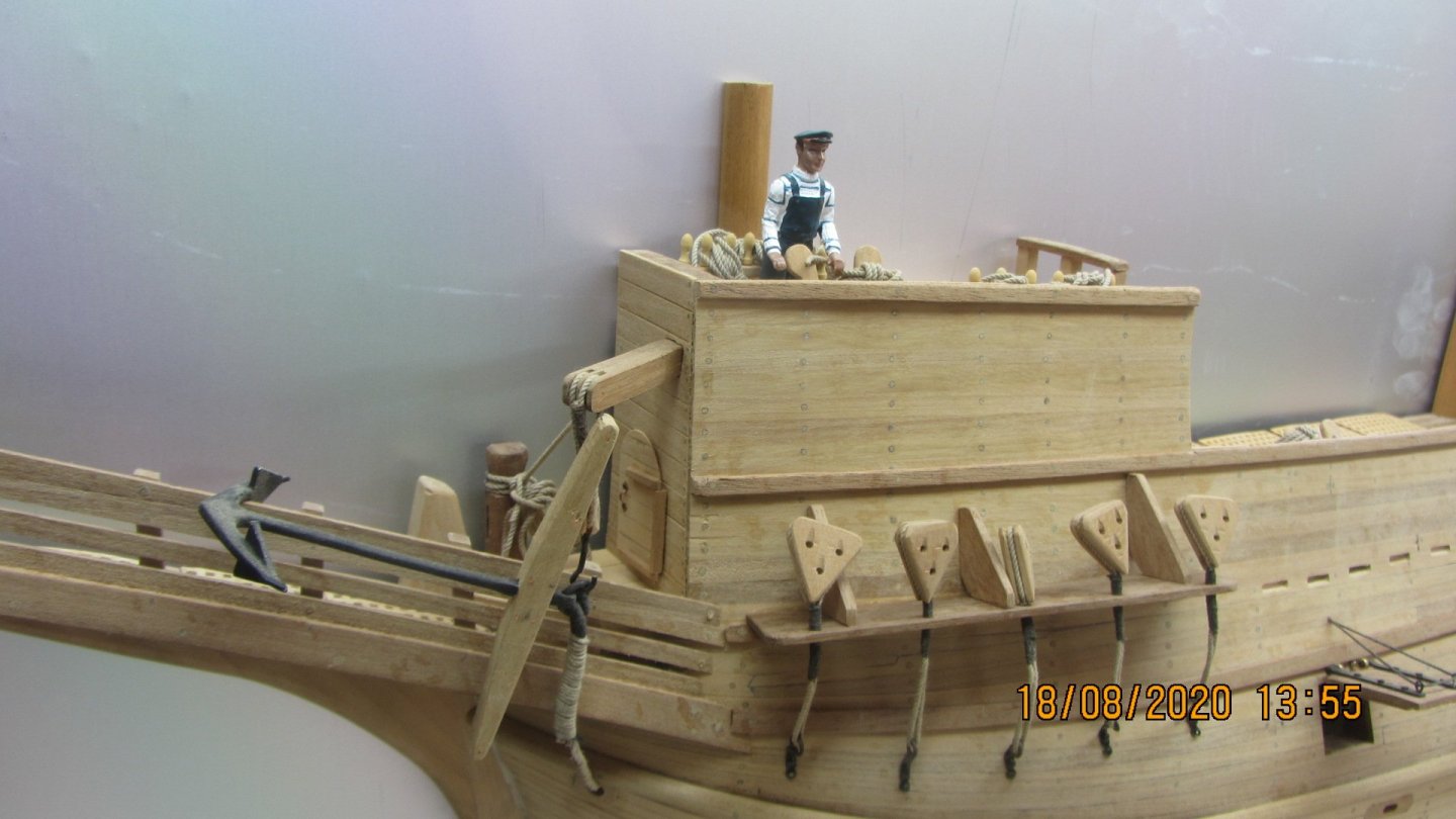
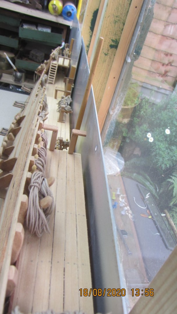
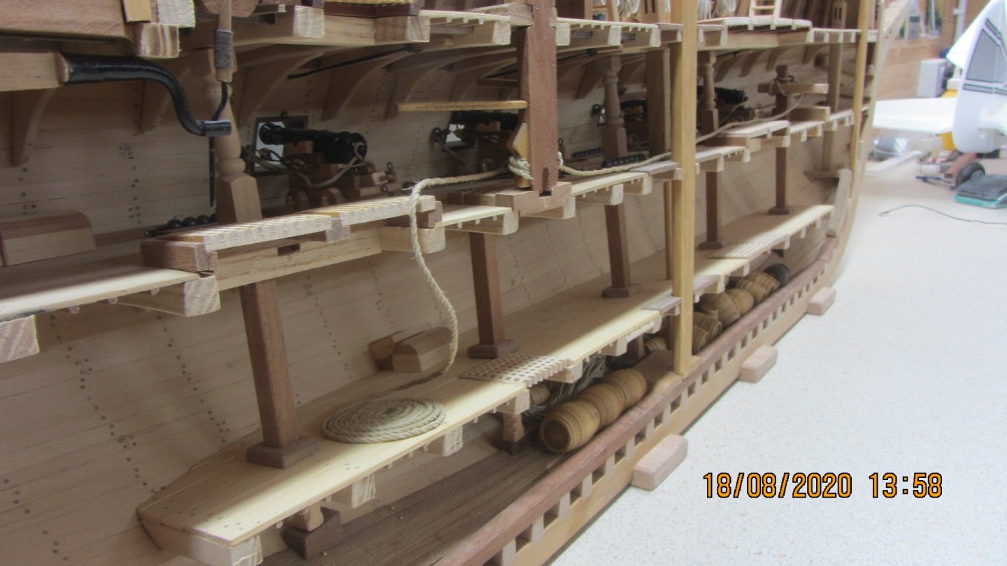
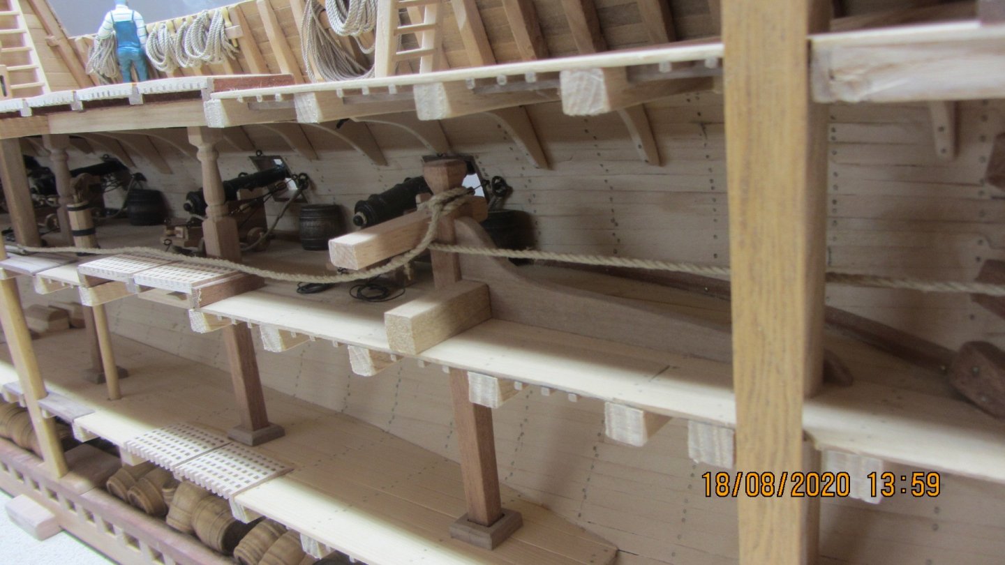
This model was built for the Plymouth Education and resource people.
They will use it as a display Hopefully for the Mayflower 400/401 as I think this years celebrations have been put back a year.
Its been a Fun build all the way through. And had a lot of help with obtaining plans and books relating to the build.
Its been a interesting concept build a cross section of this type. The wife thinks I should do a cross section at the same scale with all the timbers in place.. No mast.
Regards Antony.
- Louie da fly, egkb, mtaylor and 1 other
-
4
-
Hi.
Hi Robert. Did not check the post since October.
Its been a while but she's all finished and turned out as I expected.

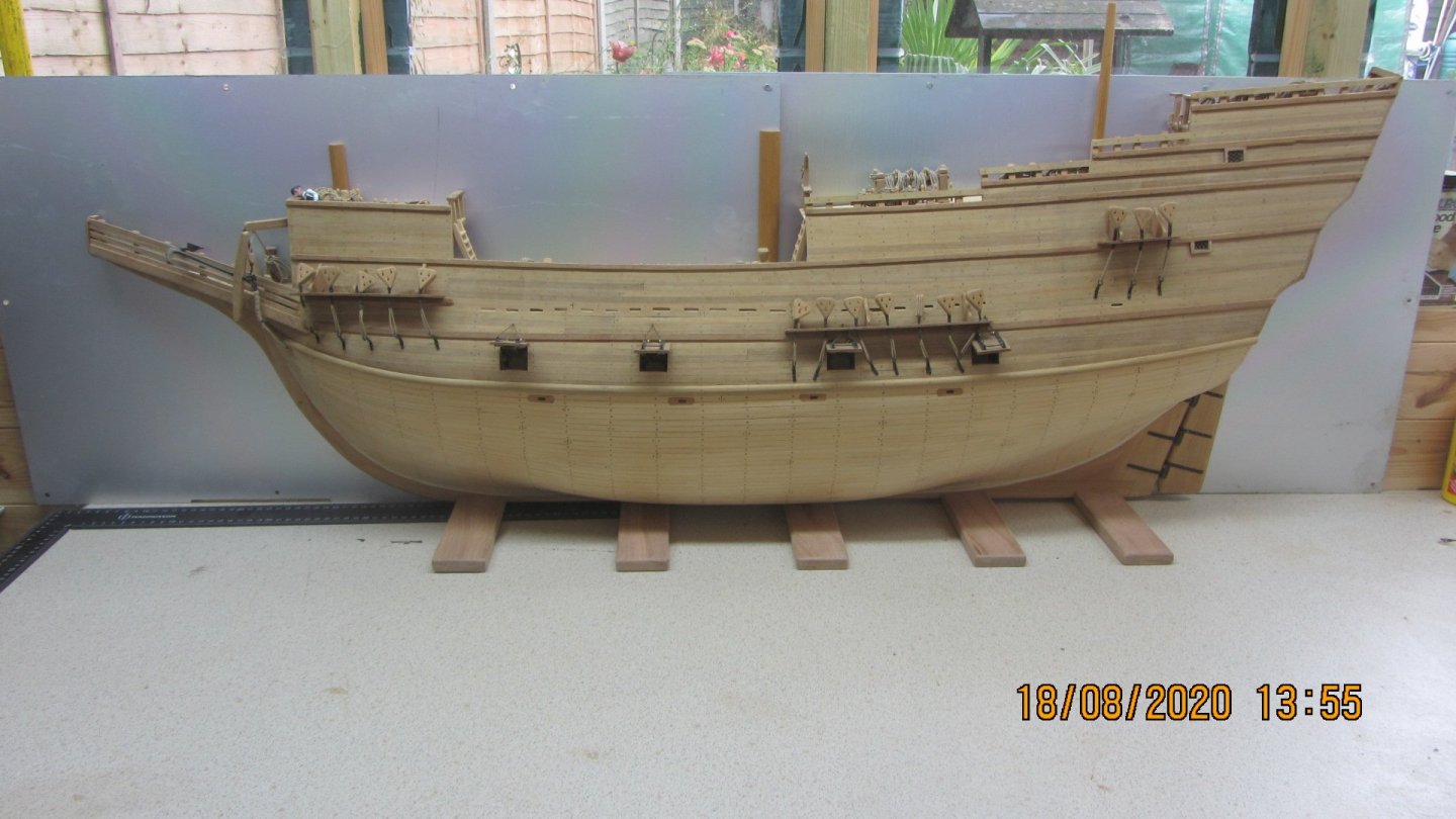
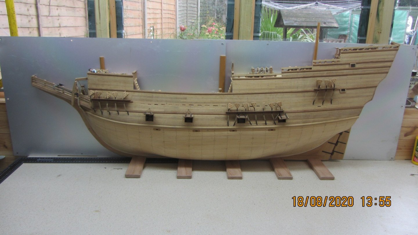


Just a little tidying of the edges and clean the dust off and she's ready to go.
Been a interesting build with Help from a lot of people from all over the globe.
Thanks for looking in.
Regards Antony.
- Mirabell61, Bob Legge, Ondras71 and 20 others
-
23


Tally Ho by AntonyUK
in - Build logs for subjects built 1901 - Present Day
Posted
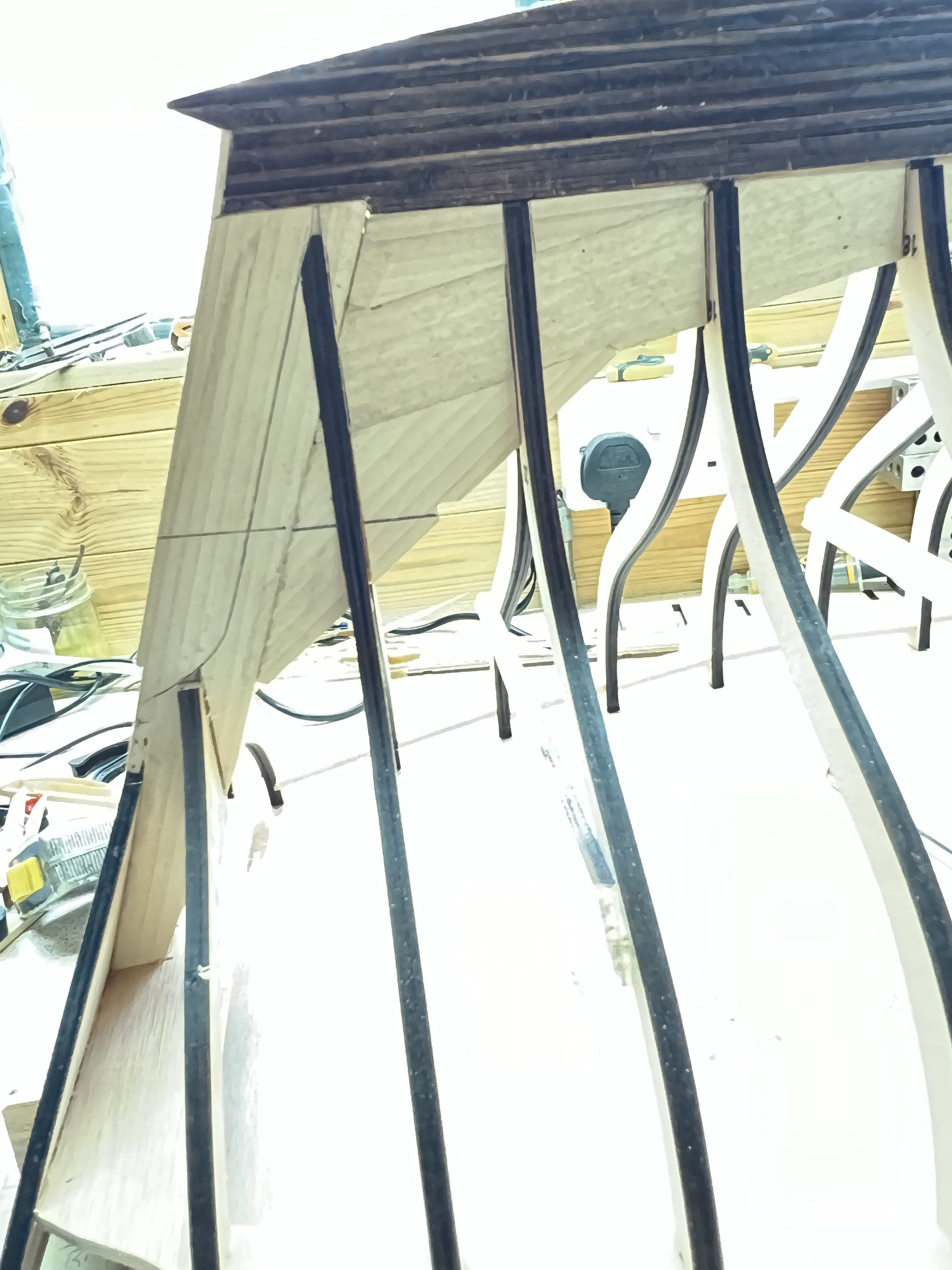
Good afternoon..
Thanks John.
Another little update.
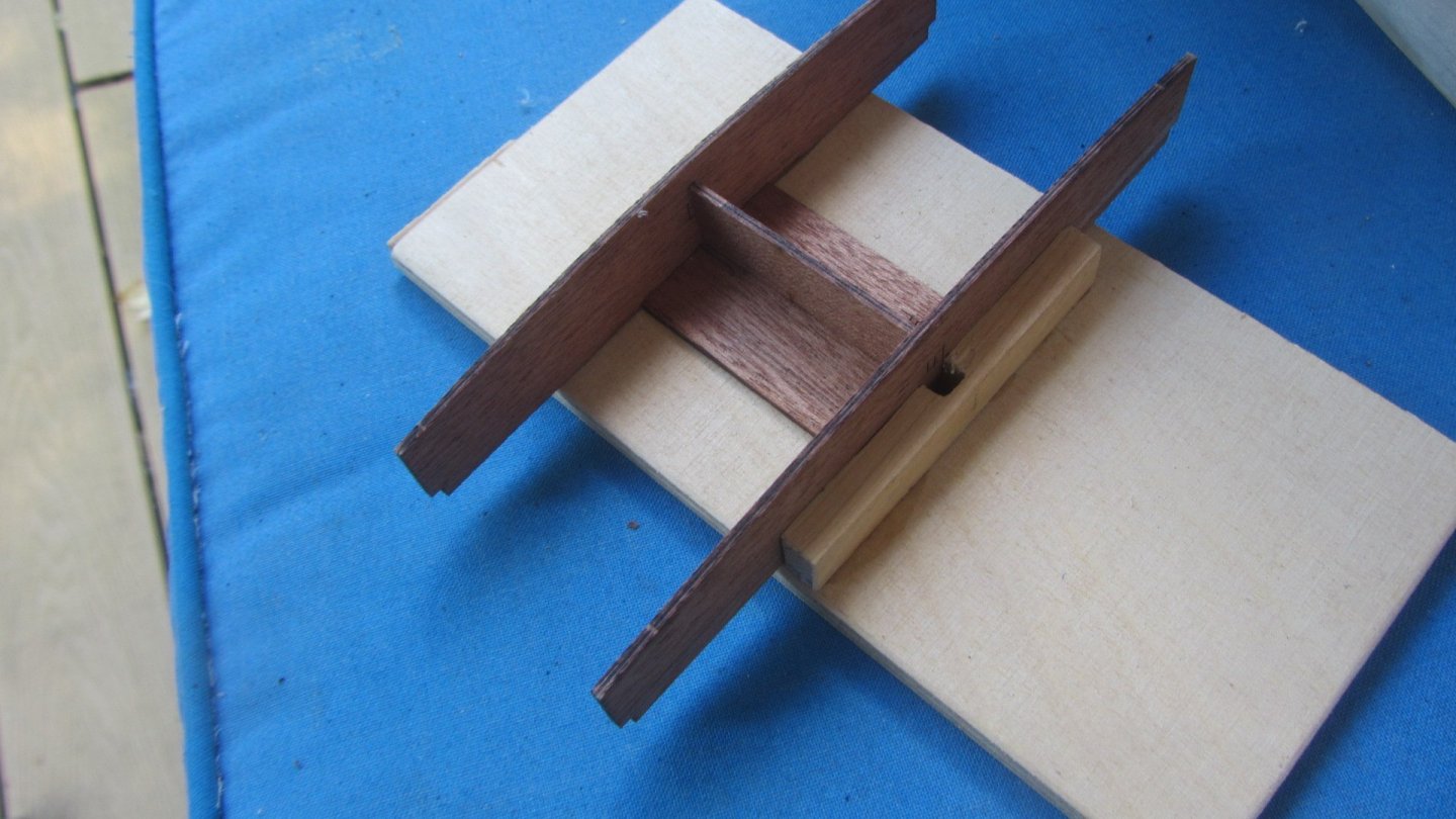
Jigs to hold the Slide rail in place while drying.
Skylight gets some finishing timbers. Lots mor to add yet. Then quite a bit of sanding to a nice finish. Not sure if I can make them opening because the hinges are bespoke and made out of brass.
Might be able to 3D print them.
Deck hatches Sliding parts. Timber at bottom is a jig for the correct curvature.
Regards AntonyUK.