HOLIDAY DONATION DRIVE - SUPPORT MSW - DO YOUR PART TO KEEP THIS GREAT FORUM GOING! (Only 27 donations so far out of 49,000 members - C'mon guys!)
×


gjdale
-
Posts
4,891 -
Joined
-
Last visited
Content Type
Profiles
Forums
Gallery
Events
Everything posted by gjdale
-
 Lovely run of planking Remco. I'm with the others though - what's to improve?
 -
Nice to see a Fubbs build Mike. I have the practicums tucked away in my "one-day" stash, so I'll follow along with interest.
-
Congrats on finishing the hawse timbers Ben - they look great.
-
Welcome home Bill - we've missed you. Delighted to hear the C.W. Hime shipyard is back in operation.
-
And he's off!............... Great start Sjors, only a few thousand more to go.
- 1,616 replies
-
- 2
-

-
- caldercraft
- agamemnon
- (and 1 more)
-
Looks like a wonderful "research" trip Toni. Thanks for sharing the photos.
-
Nice paint job there Sjors. No more putting off the coppering now - on with it!
- 1,616 replies
-
- 2
-
-
- caldercraft
- agamemnon
- (and 1 more)
-
Wonderful work Danny. A real joy to watch.
-
Ian, Jeff Hayes (of Hobbymill) has posted on his website, a guide to operating the Byrnes saw, including a page on blade selection that also has clear pictures of the Thurston brand blades he uses. Here is a link to that page: http://www.hobbymillusa.com/byrnes-saw-operation-2.php And here is a link to the Thurston website where you can download a catalogue: http://www.thurstonmfg.com/index.html Hope this helps.
-
Sometimes it's wise to walk away for a while Ben. Glad to see you're back to it though.
-
Wow, that really does show how much wider she'll be with stuns Kevin! I think. You'll have quite a unique presentation in the end - looking forward to seeing that. Nice companion stair btw.
- 1,319 replies
-
- 1
-
-
- caldercraft
- Victory
- (and 1 more)
-
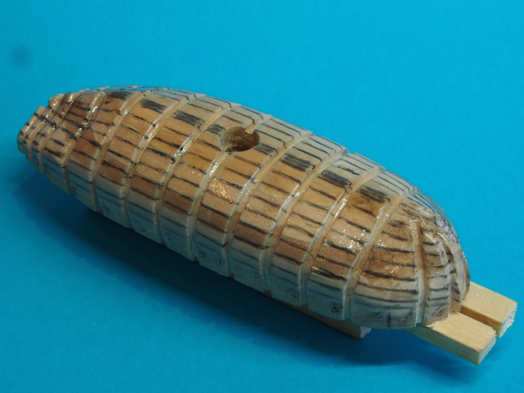
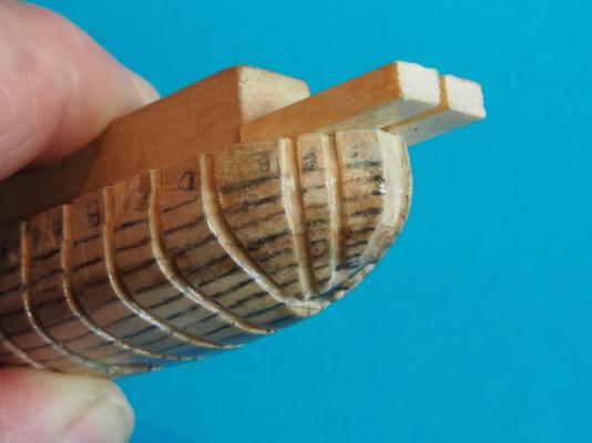
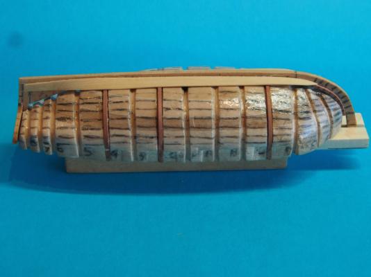
Thanks B.E., JesseLee and Sjors (and all of the "likes") - your continued support and encouragement has really kept me going of late - I've come within a hairs breadth of giving up on these little cutters, but the support from all of you helps me to keep things in perspective and resolve to continue. So Sjors, they very nearly did become UFOs (UnFinished Objects) 25' Cutters (continued) The last few days have been somewhat "challenging" (the air in the shipyard is still an interesting shade of blue, and my long suffering wife has learnt to keep well away from the shipyard of late, occasionally slipping food and drink through the door). The first issue I had to resolve was how to hold the keel/backbone assembly rigid in the plug while I applied the planking. I would like to acknowledge here the very kind assistance of Greg Herbert (dvm27), who was good enough to answer a number of PMs while I quizzed him about the method used by he and David Antscherl, while I searched for a way to apply that thinking to my own version of their technique. Greg suggested adding an extension to the fore section of the plug to grip the stem, so that is what I did. I was also trying to figure out the lining out of the hull, and had been a little stumped by the placement of the Garboard strake. Again, Greg offered a little advice and I managed to work it out from there. After lining out the plug hull, I gave it several coats of sanding sealer to both preserve the lining out markings, and prevent the planks from inadvertently sticking to the plug. In these two pics, you can see both the lining out and the "Herbert Horns" (as I've dubbed them): Then it was time to fit the Garboard strake. This gave me more grief than I am capable of describing, but we got there in the end. Here's a couple of pics of the Garboard in place. (Remember also that while I'm showing pics of one boat, I'm building two of them simultaneously). In these photos, you can also see a couple of frames in place. These were an experiment and were designed to be "sacrificial" frames. The idea was to spot glue the keel to them to assist in keeping the keel rigid. I attached four such frames to each boat. It didn't work - I suspect due to insufficient gluing surface (the keel would come away from the frame at the slightest provocation). The upper end of the stem is glued into the gap between the Herbert Horns. One of the issues I have been facing is finding a way to clamp the pieces in place while the glue dries. This has been my single greatest source of frustration , but I eventually managed to find a way using a variety of different sorts of clamps. Nevertheless, I did find that there was a slight gap in places between the Garboard and the keel. This is partially because I could not see a way to cut a proper rabbet into the keel at these dimensions. Time then to try a new product...... and the winner is, Superphatic Glue, by Deluxe Materials (the RC Aircraft modellers will probably be familiar with this stuff). It is an ultra thin aliphatic glue that also has a strong wicking action. I was able to use this to run along the slight gap and wick into it. I was very pleased with the result as it made the bond between Garboard and Keel quite strong (as I found out later.......) I then went to the next plank for each, spiling using the tape and pencil method described previously to create a card template before cutting the plank. Oh, by the way, I'm using 1/64" thick Boxwood for the planking this time around. It is very nice to work with, and while not quite as pliable as Holly, it's not far off at this thickness. Before fitting, the upper edge (i.e. closest to the sheer line) of the Garboard plank was sanded to slight chamfer, and the "under edge" of the next plank was likewise chamfered. This creates a better overlapping join and something of a flat mating surface for the glue to grip onto. Once again, clamping was a real issue and the delicacy of the parts was proved several times as I managed to break both stems and both sternpost/transom assemblies. This was when I discovered how good the bond between the Garboard and keel was, as the "shell" came away from the plug completely, with planks and keel in tact. At least that was reassuring and I now know that I shouldn't have a problem with the planks sticking to the plug! Here's a couple of pics of the the second plank in place. The Apron on the bow is proving quite useful as an alternative to a Rabbet, as it gives the planks a landing place along the stem. In these pictures you can also just make out the "gain", which is where the overlapping of the planks disappears at the bow so that they are flush to each other along the stem. Well, I've now been on leave for two weeks. At the start of this period, I had hoped to have completed these two boats by the time I went back to work. Instead, I seem to be further behind than when I started. Oh well, at least some learning has taken place! Hopefully, the planking will get a little easier from here on (famous last words!). Stay tuned........


-
Congrats on reaching this milestone Sjors - looks good. Bet you can't wait for the coppering!
- 1,616 replies
-
- 2
-
-
- caldercraft
- agamemnon
- (and 1 more)
-
Nice set up Danny, even if a little cosy. Very well organised too - puts my workshop to shame! Looking forward to seeing the resumption of play with Vulture.
-
That must have been a "heart in the mouth" moment Mark! Well done though - as you and Michael observed, there's always a way.
-
HMS Druid by Krug - FINISHED - 1:48 - Hahn
gjdale replied to kruginmi's topic in - Build logs for subjects built 1751 - 1800
Congratulations again Mark. Your final tweaking on the figurehead was worth it - it looks great. Reading through your stats, the one that stood out to me was the addition of two kids, making six in total - I would normally tell someone with that many kids that they seriously need a hobby................................. I don't know how you managed to fit in the ship modelling in amongst all of that - I have had enough trouble finding time bringing up just one kid over the time I've been modelling, and the really serious work didn't start until he left home! Looking forward to your next scratch build. -
Very nice repair job JesseLee, and a very clever one at that.
- 607 replies
-
- 1
-
-
- scottish maid
- artesania latina
- (and 1 more)
-
Amazing Remco, but we shouldn't really be surprised now should we? Just fantastic!
-
Sweet! I'd recommend getting some of Chuck's rope Mobbsie - it really is good quality and virtually no fuzz.
- 1,279 replies
-
- 1
-
-
- agamemnon
- caldercraft
- (and 1 more)
-
Your windows look great. A pity about those decorations - I think some modifications might salvage them though.
-
HMS Druid by Krug - FINISHED - 1:48 - Hahn
gjdale replied to kruginmi's topic in - Build logs for subjects built 1751 - 1800
Very well done indeed Mark. Congratulations on getting to the finish line - you should be justifiably satisfied and proud of your achievement. What's next? -
Fantastic work with those nails Jack - they really make a difference!
-
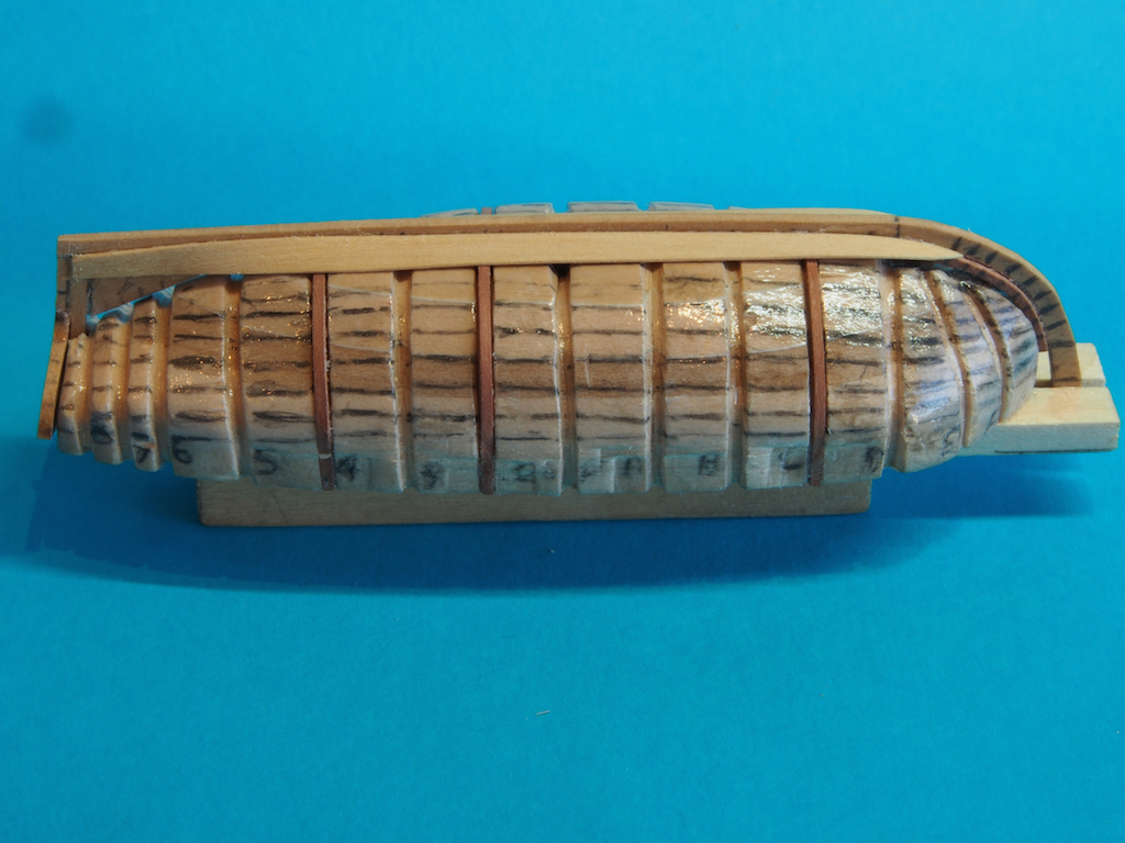
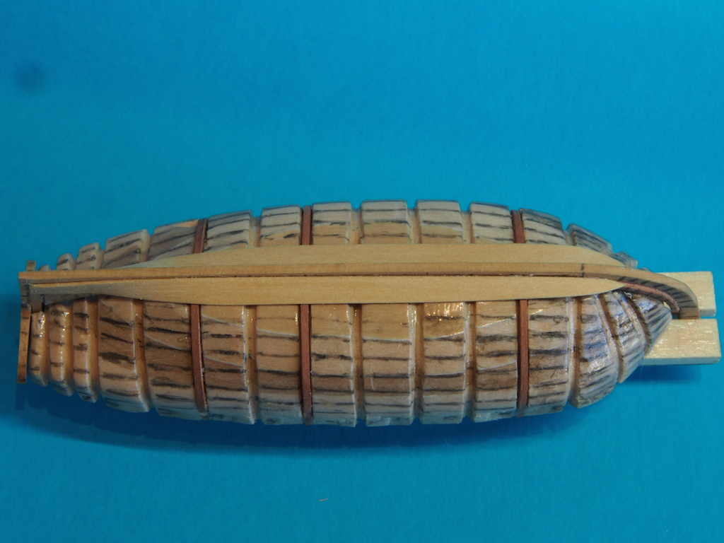
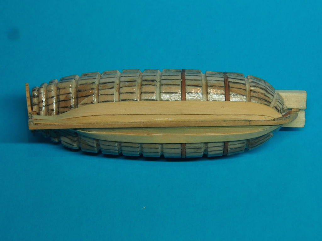
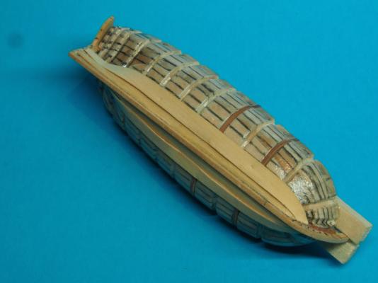
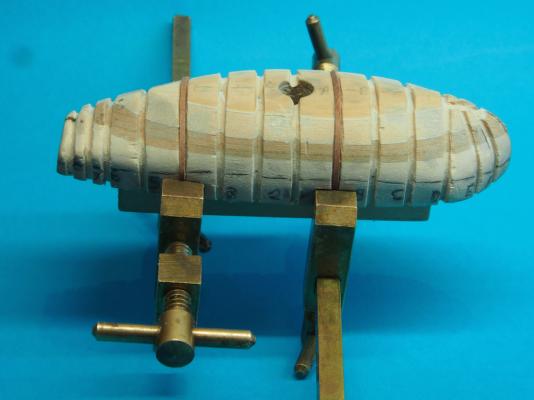
Thanks Mobbsie, Michael and Mike (and all the "likes"). Cutters Ver 2.0 (continued) Well, these little boats have certainly been a case of experimentation, re-do and "make it up as you go along"! Fortunately, I've had a couple of weeks leave to work on these, so this has given me some thinking space - and boy, have I needed it! I said previously that I'm basically following the method used by David Antscherl and Greg Herbert, with some modifications. One of those was to be that I did not intend to carve grooves into the plug for the frames, intending instead to simply bend the frames over the plug lines. I tried this, using a double laminate of 1/64" x 1/16" Holly and found two things not to my liking: 1. The frames became increasingly difficult to keep straight on the lines as I moved towards each end. 2. At 1/16" wide, the frames looked too wide for the scale (Antscherl/Herbert used 1/16" square stock at 1:48 scale, so it's not surprising really). So, there was nothing for it but to scrap another day's work and re-think. I decided to have a go at carving grooves into the plug - this to make it easier to keep the frames aligned. At this point, I also modified the framing plan slightly to incorporate a couple of cant frames forward - previously they were all square frames. The grooves were cut by first scoring with an Exacto blade, then working over with a knife edge file, and finally a square edge file. I also decided to change the dimension of the frames to 1/32" square stock. This would be in keeping with Antscherl/Herbert adjusted to 1:90 scale. Unfortunately, I didn't have any Holly of this dimension, so decided to use Pear instead. To make it more flexible, I soaked the Pear strips in water until they no longer floated. Then I carefully bent them over the plug and clamped them in place to dry. Here is a couple of pics of the carved plug with a couple of frames clamped up. When it came to the last three frames at the stern, even the super soaked Pear wasn't playing the game. After scratching my head for a while and wishing for some Holly of the right dimension, I answered my own question. I took some 1/64" x 1/16" Holly strip and very carefully split it in half to give dimensions of 1/64" x 1/32". By laminating two of these together, I could achieve the 1/32" sq dimension overall, while having the advantage of the very thin and very flexible Holly to bend into the stern frames. The different coloured timbers of the frames won't be seen as the boat will be painted anyway. A bit hard to see in this pic, but there is a laminated pair of Holly frames being formed under the mini-clothes pegs. The pegs gave just the right clamping profile to help with the reverse shape of the frame curve. Lastly, here is a shot of a few of the finished frames. They have been labelled as they are too small to actually write on (1/32" sq is about 0.8mm sq for the metric folks). The Holly double laminated frame is in the top left corner (labelled '6'). Now that this method seems to be working out, the next task will be to line out the hull and then plank it. Before I can do that though, I will need to re-surface the plug with sanding sealer/wax............ Still got a few frames to finish off first though. Stay tuned.......

-
The "first CUT is the deepest"
gjdale replied to AndrewNaylor's topic in Modeling tools and Workshop Equipment
Andrew, Micromark sell a couple of digital depth/height gauges that are relatively inexpensive. The method described by Nigel also works well.