Ian_Grant
-
Posts
2,156 -
Joined
-
Last visited
Content Type
Profiles
Forums
Gallery
Events
Everything posted by Ian_Grant
-
 Bill I believe I just bent a bit of brass wire to shape, with small bits of evergreen for the feet. Tried to take a pic just now through the case but it's hard to see behind the stunsail boom and the sheet block itself. Camera also seems to have had difficulty focusing through the case.
-
Looking good! I must dive in and try one too..........
-
Never heard of that story either. The Doolittle raid in reverse.....
-
Bruce - Yes, I-400, that was it! Tamiya has a large model as here: https://www.ebay.com/p/1800179449
-
Recently returned from a vacation in Hawaii. On our last day we flew to Honolulu and went to Pearl Harbour before flying home that night. In the fleet submarine museum next to USS Bowfin, there was a model of a large Japanese submarine which carried aircraft. I had never heard of this. Are there any models available, does anyone know?
-
Bill, glad to hear that the sheets and tacks will work out. According to Longridge all yards except the cro'jack used "dog and bitch" thimbles see Fig 169 pg 238. The cro'jack yard is the only yard with brace pendants (pg 258). From Plan 7 they seem to be of a length which would reach from the yardarm to the outer stirrup of the cro'jack foot rope. keep up the good work. Nearly there! Looking forward to your SR too. 😃
-
Hi Bill, I take it you are referring to such lines as the fore t'gallant sheets and clewlines, and others, belaying just above the lower deadeyes as mapped in Longridge Plan 10 and 11. Unfortunately, these belay on the inside (one would not want to have to climb out onto the channels to access them). Belaying is by means of shroud cleats attached on the inside of the shrouds, as depicted in Fig 142 on pg 214. These lines also pass through "trucks" lashed higher up the shroud; a truck is shown in Fig 141. These prevent the lines from tangling around each other when slack. I don't think these lines pass outside the mast top. In the case of the t'gallant clewlines, as described on pg 249 they lead from the block on the t'gallant yard to leading blocks attached to the after cross tree, then down from there (see the 7" topgallant clewline block depicted in Plan 9). Since these leading blocks are so close in to the mast, in my view the lines then pass through the lubber's hole, through a truck attached at the top of a shroud, then down to the shroud cleat. Similarly, the t'gallant sheets run from the topyard quarter block down through the lubber's hole to their shroud truck. On my model I omitted these trucks, which would be well nigh impossible at this scale, but I did make shroud cleats by attaching small etched brass cleats to small bits of evergreen on the back of which I filed a concave round to allow gluing more effectively to the shroud. I don't have a great shot of them, but here is one anyway. If you look across the ship on the starboard shrouds just to the right of the tip of the sheet anchor's stock, four shroud cleats can just be made out. It would have been less work to simply tie the lines on the inside of the shroud, but at the time I was carried away by the masterful work I saw on the old Pete Coleman Victory model web site. 😆😬 You can decide what lengths you want to go to for your model.
-
Bill I replied o this topic in post #1298, however I see I just used the phrase "on the forecastle". By this Longridge just means to timberheads along the beakhead rail, above the roundhouses. They end up with 3 or 4 lines apiece 😬.
-
Bill, all the topmen used the futtock shrouds. It's the fastest route to the topmast ratlines to get to the critical topsails. If someone had used the lubber's hole he'd have been shamed and maybe even punished for endangering the ship.
-
Glen, just got back from vacation......your treasure fleet is an awesome presentation, outstanding creativity! 😲
- 194 replies
-
- 2
-

-
- Bottle
- Treasure Fleet
- (and 3 more)
-
Didn't know where to post this but thought members may be interested. https://www.msn.com/en-ca/money/markets/how-a-canadian-coffee-roaster-is-replacing-container-ships-with-sailboats-to-decarbonize-its-supply-chain-—-and-cutting-costs-in-the-process/ar-AA10WiKc?ocid=mailsignout&li=AAggNb9
-
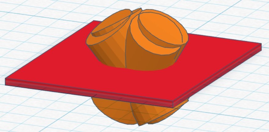
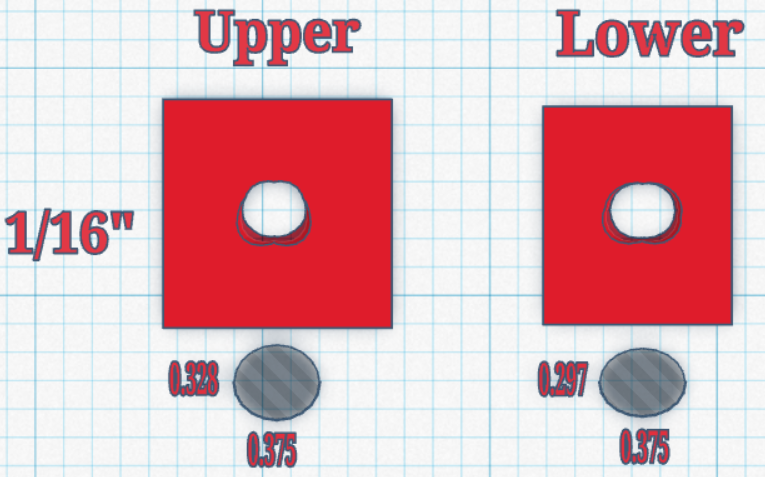
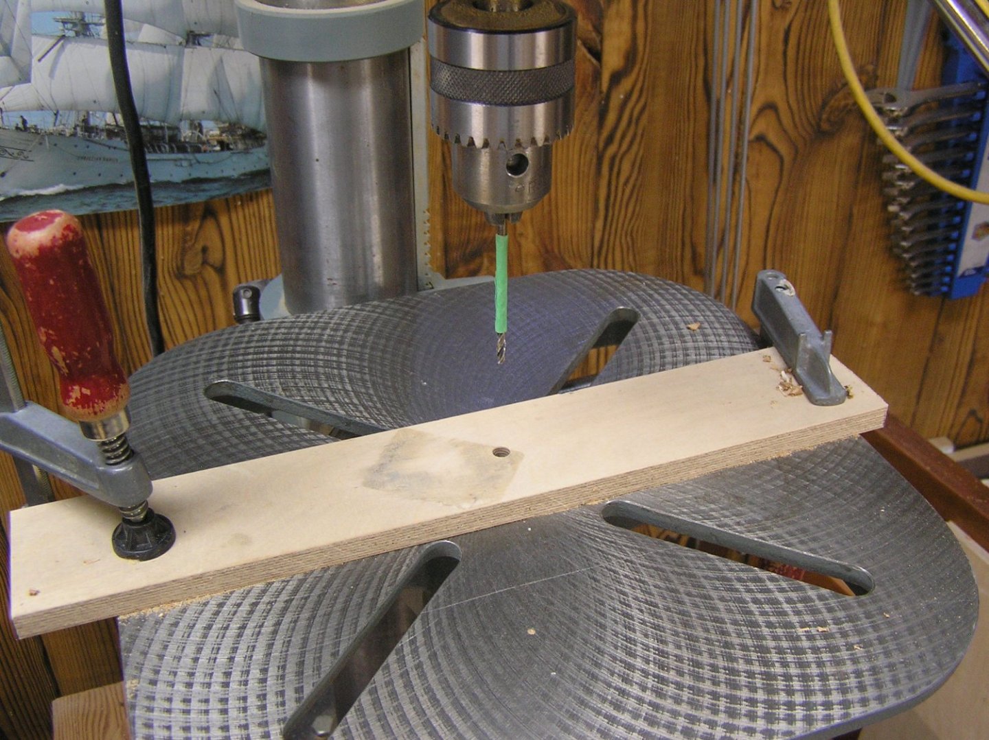
Continuing with test build for two full remes. I used TinkerCAD to sketch a section of the side of the ship, 1/16" thick, pierced by four cylinders representing an oar shaft at the four extreme positions of the oar. Goal is to find minimum size and shape for thole hole which allows rowing without being too much of an entrance for water. Here is a screen image. Then I change the cylinders from "Solid" to "Hole" and "Group" the lot. This leaves the red plate with the ensuing hole. I drew two cases, for the lower and upper remes, since the angles are different i.e. the lower oars' vertical range includes horizontal, whereas the uppers are angled down whether in or out of the water. Here is the result: The shaded ellipses at the bottom by my judgement are more or less equivalent to the cutouts in the plates. You can see that the upper reme requires a taller opening, since these oars pass through at a steeper angle. For the lower reme, a suitable "ellipse" can be formed by using a 7.5mm (0.295") brad point drill bit to drill a pair of holes offset by 5/64" (gives an oval 0.295" x 0.373"). My old eyes had trouble seeing the 64ths marks on my ruler so I just used a slightly heavy 1/16". Using a jig on the drill press I was able to drill a nice line of 22 of these ovals in a strip of 1/16" plywood, which is what I plan to use at this location on the actual model. This strip was then mounted on the baseplate of the jig, with height over waterline, and spacing from the mechanism, matching the planned values for the model. Once this was in place, the lower oar attachment strip was mounted on the beam such that the fully down beam position yielded horizontal oars, and all 22 oars were attached. Here is a little video. I just used the 2-channel RC set to move in each dimension. We're leaving on vacation tomorrow and I don't have time today to hook up the Arduino, get myself back up to speed on the software, and alter the servos' movement ranges to suit the new mechanical setup. The beam only has to move up and down by 3/8" to move the oars from in the water (measuring against the blue surface level) to horizontal. This is exactly as calculated in earlier drawings, thanks to the reduction in loom length to 1.5" from 2". I mention that the oars have a lot of play in the sweep direction. This could be problematic in terms of having another set of oars from the upper reme interlaced with them at only 5/8" spacing. It would be ok during the power stroke because all oars would be pressing on the forward ends of their thole holes, and they'd all be aligned nicely, assuming I drill the thole holes and mounting screw holes accurately. But once lifted into the air on the return stroke they're liable to be flopping all over and perhaps hitting each other. My first reaction was, "Damn, I'm going to have to add thole pins and strap the oar shafts to them like in the real thing". I'm reluctant to get into this, with the prospect of strings breaking and continual upkeep with poor access. All I really need is some way to "gently" continuously nudge the shafts to the forward ends of their holes, where they will naturally place themselves during the power stroke. I thought of lashing all the oars in a reme together just inside the bulwark with a rubber band tensioning the forward end; doesn't sound too practical either. Perhaps a rubber band on each oar? Nah! Then I thought of having a rubber o-ring placed just aft of each oar, with its aftermost quarter siliconed to the inside of the bulwark, or a rib of the model, and its free end just pushing the oar shaft against the forward end of the thole hole. When the shaft has to pivot aft for the return stroke it can just flex the o-ring into a vertical ellipse. There wouldn't be appreciable additional stress on the sweep servo since the o-ring is right at the pivot point. Hmmm, maybe. It has now been a whole year since I started farting around with this 😒, albeit I spent much of last winter on rigging another model. The Admiral must be sick of hearing about it. I really really hope I can start on the actual hull this winter. Just want to add 2nd reme to this jig and satisfy myself that I can make a bireme work, whether with o-rings or some other idea. (monoreme woudn't be an issue, perhaps that's why videos I see are all monoreme RC models??). Or just maybe I will add the 2nd reme and there won't be a collision issue 😬. One can hope. Thanks for reading!
- 536 replies
-
- 6
-
-
- Quadrireme
- radio
- (and 1 more)
-
Soleil Royal by yancovitch
Ian_Grant replied to yancovitch's topic in - Kit build logs for subjects built from 1501 - 1750
Vic, you "took a break to make a case"........ since YESTERDAY!? 😲 ...you put me to shame.... -
Bob, Very nice model! Your blocks and strops look good. My only comment, for reference with future builds, is that the main stay should not be bent out of its true path by the fore braces. The thick stay is under a lot of tension and would not be readily distorted. I apologize for this critique; I offer it purely to add to the fidelity of your future builds. Keep up the good work! Looking forward to your next log.
- 146 replies
-
- 1
-
-
- Harriet Lane
- Model Shipways
- (and 1 more)
-
We need some new icons to click on - "Wow" just doesn't cut it for Valeriy's build. "Awestruck" or "Filled with Amazement" or even "Lost for Words".
-
Agree on the Alexandria diorama. But looking at those hands, isn't the artist a "she"?
-
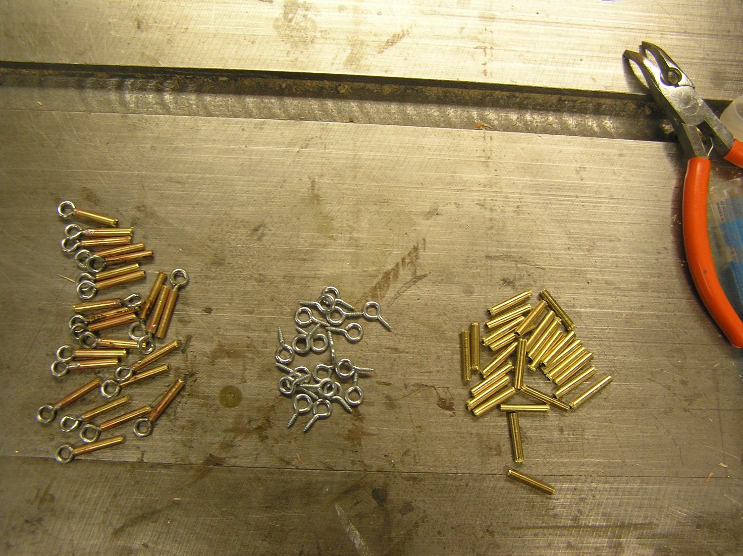
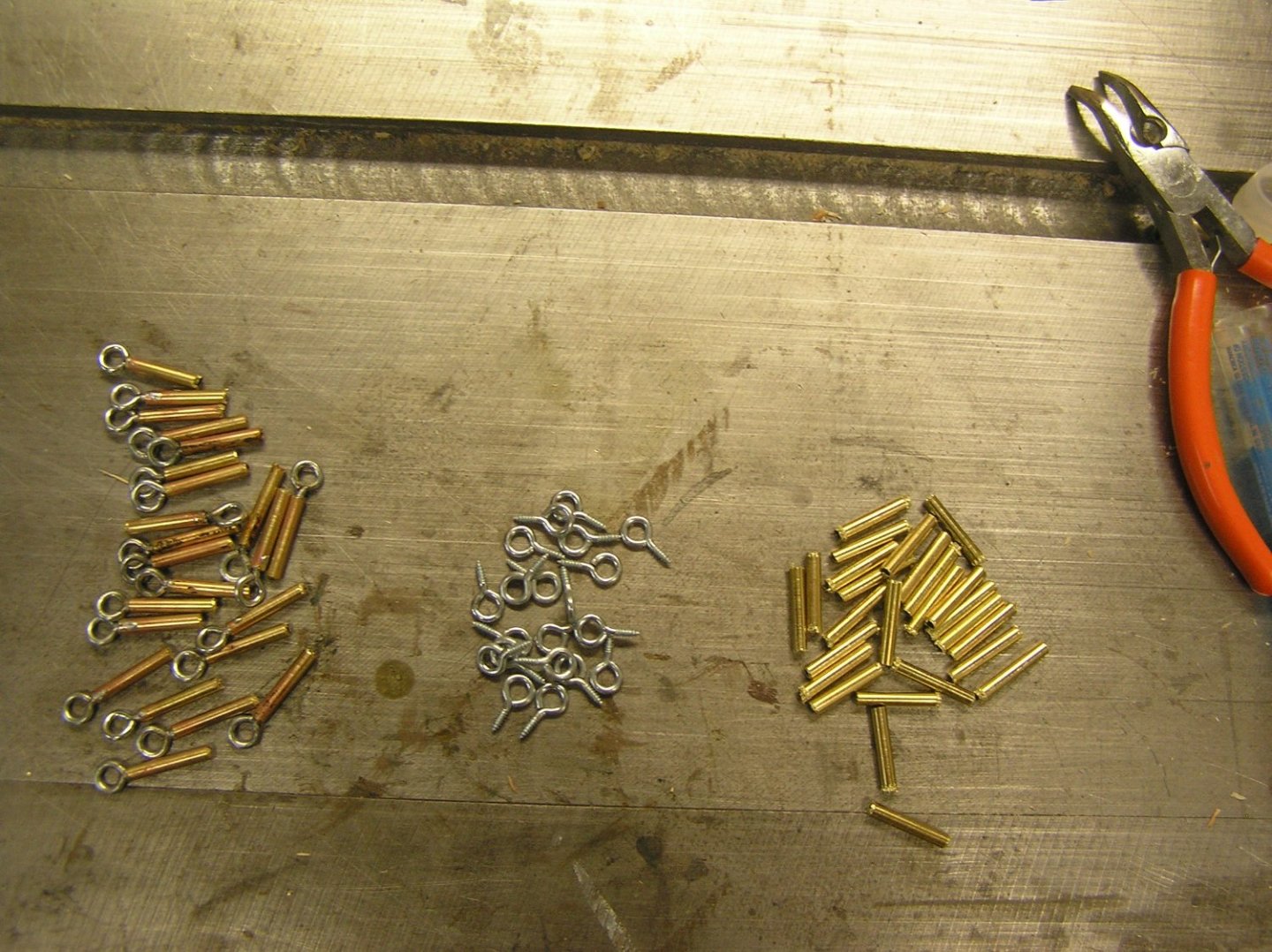
Forty four oars (enough for one side) in production. Here are assembled shafts, blades, ferrules. Blades are from cherry cutoff I had lying around which will be beautiful when varnished, but shafts are plain "hardwood dowel" as sold at Home Depot etc. Lee Valley has nice cherry dowel but only 1/2" and up. Might try to stain shafts. I must have miscalculated how many strips to cut up for blades; I still have 77 left to choose from, for 44 more oars (plus some spares). Now soldering screw eyes into short brass tubes. Tedious cutting the brass. Once finished these will be epoxied into the holes drilled in the loom ends using a simple jig to keep consistent projection of the eyes. Then all can be mounted on the oar beam for a trial of two full remes rowing, controlled by the arduino. But this exciting test will have to wait until we return from holiday in Hawaii.

- 536 replies
-
- 6
-

-
-
- Quadrireme
- radio
- (and 1 more)
-
Glen, I'm speechless with amazement! You even have Shiloh smaller, and hornless! Fabulous, outstanding, extraordinary........and whatever other superlatives you can think of. This bottle display will be truly memorable.
- 194 replies
-
- 3
-
-

-
- Bottle
- Treasure Fleet
- (and 3 more)
-
Soleil Royal by yancovitch
Ian_Grant replied to yancovitch's topic in - Kit build logs for subjects built from 1501 - 1750
Baker, she's a great-looking build, especially for a 22 year old kid! -
Rob, I would not have thought it possible to add the jackstays, certainly not in the 70's during my build, at my then age! Amazing! But did you also add the safety stays? 😆 Or were they a windjammer innovation? Kevin the multiple glue lugs on the masts are not authentic. Keep the ones where you want to attach the upper yards; they can represent the parrals. File off the unused ones.
-
Soleil Royal by yancovitch
Ian_Grant replied to yancovitch's topic in - Kit build logs for subjects built from 1501 - 1750
Vic, she looks fantastic! The stern statues you lowered look even more "in place" in this side view. She looks very lofty even with your shortened topmasts; I think I will do the same if/when I get to mine. You even have me wondering whether to try making a wood underwater hull for mine, although I would just leave the topsides, lacking your talent. -
Happy Birthday Bill! That's a big one 😃. Enjoy your trip! We are off to Hawaii next week, Westjet permitting ✌️🤞. Victory is looking great. I too used brass rod to replace the belaying pins at the bulwarks.
-
Yes, the two parts #89 at the main mast. These lines are replicated each side of the ship, so a total of six lines pass through the deck gratings, three each side. Longridge's Plate 46 opposite pg 196 shows these bitts. As shown the jeer and clew lines belay at the after bitts. As stated, the topsail sheets belay at the forward bitts. Have a look at Plan #8 "Fore Top and Fore Yard". The two 8" topsail sheets are not shown, I suppose for clarity, but as noted they pass through the two large 26" blocks under the yard near its centre, then outboard to other 26" blocks at the yardarms. The clew lines are not shown either, but they pass through the two blocks hanging near the end of the octagon section of the yard, one of which is labelled "15" shoulder block for 4" clue line". (I have never liked the spelling of the clew line as the clue line). The huge pairs of blocks above the yard are the jeer blocks. Their 7.5" falls pass behind the yard and on down. The jeers are described on pg 241. Note the line sizes. The clew lines are much smaller since they do not take the huge strain that the jeers and topsail sheets must bear. The jeer and topsail sheets are best represented with 0.5mm thread at scale; the clew line by 0.25mm thread. Don't worry, by the time you have worked your way through this model's rigging using Longridge (instead of Heller) you will know all the jargon. 😃
-
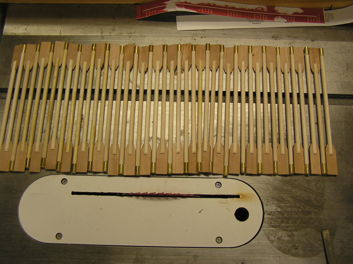
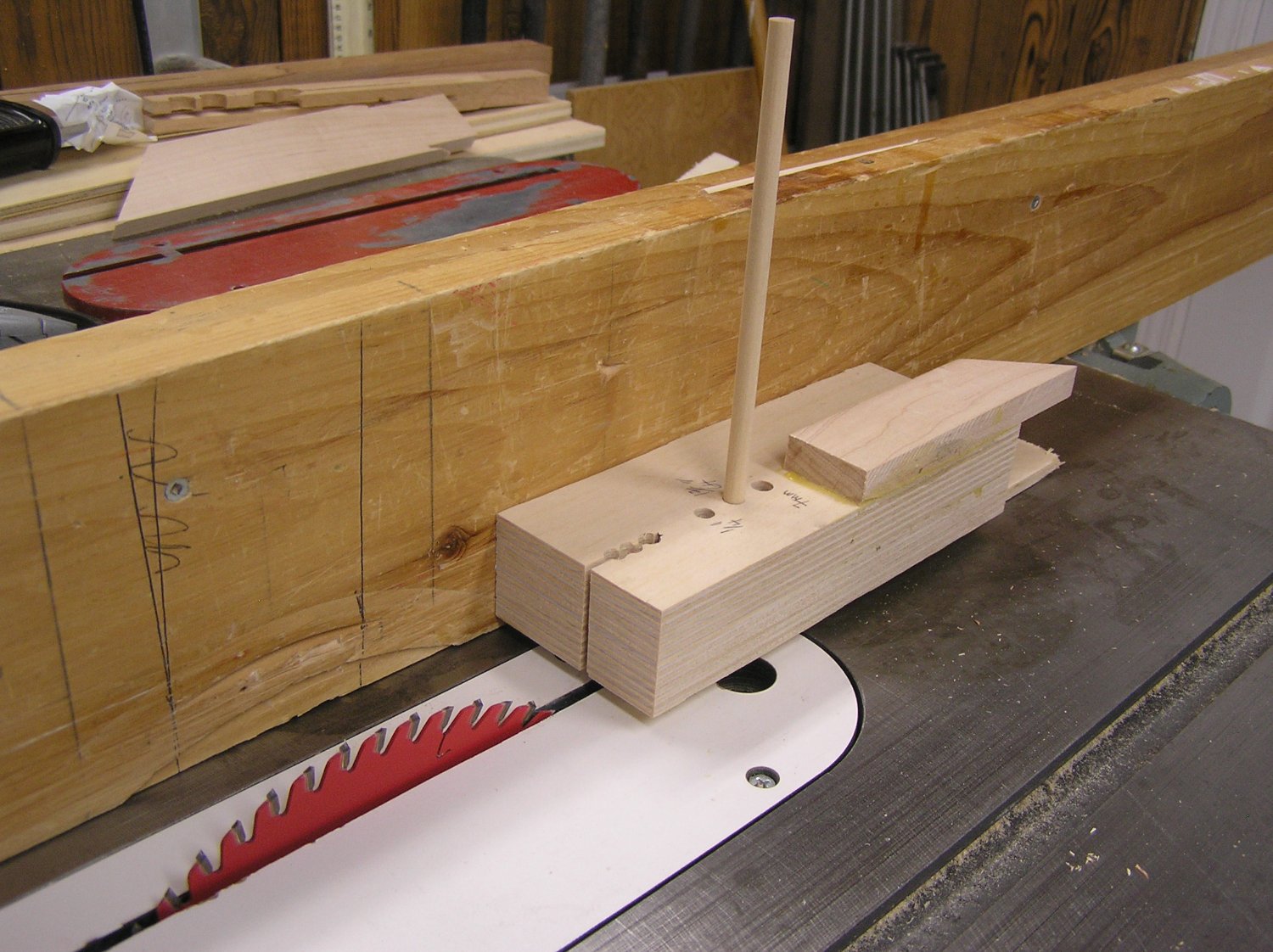
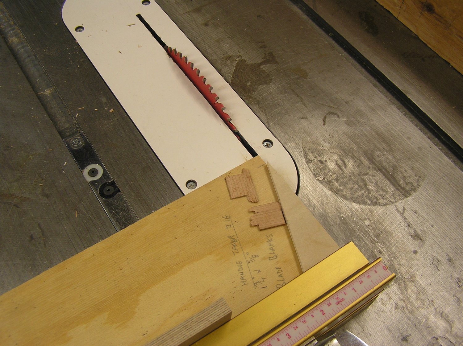
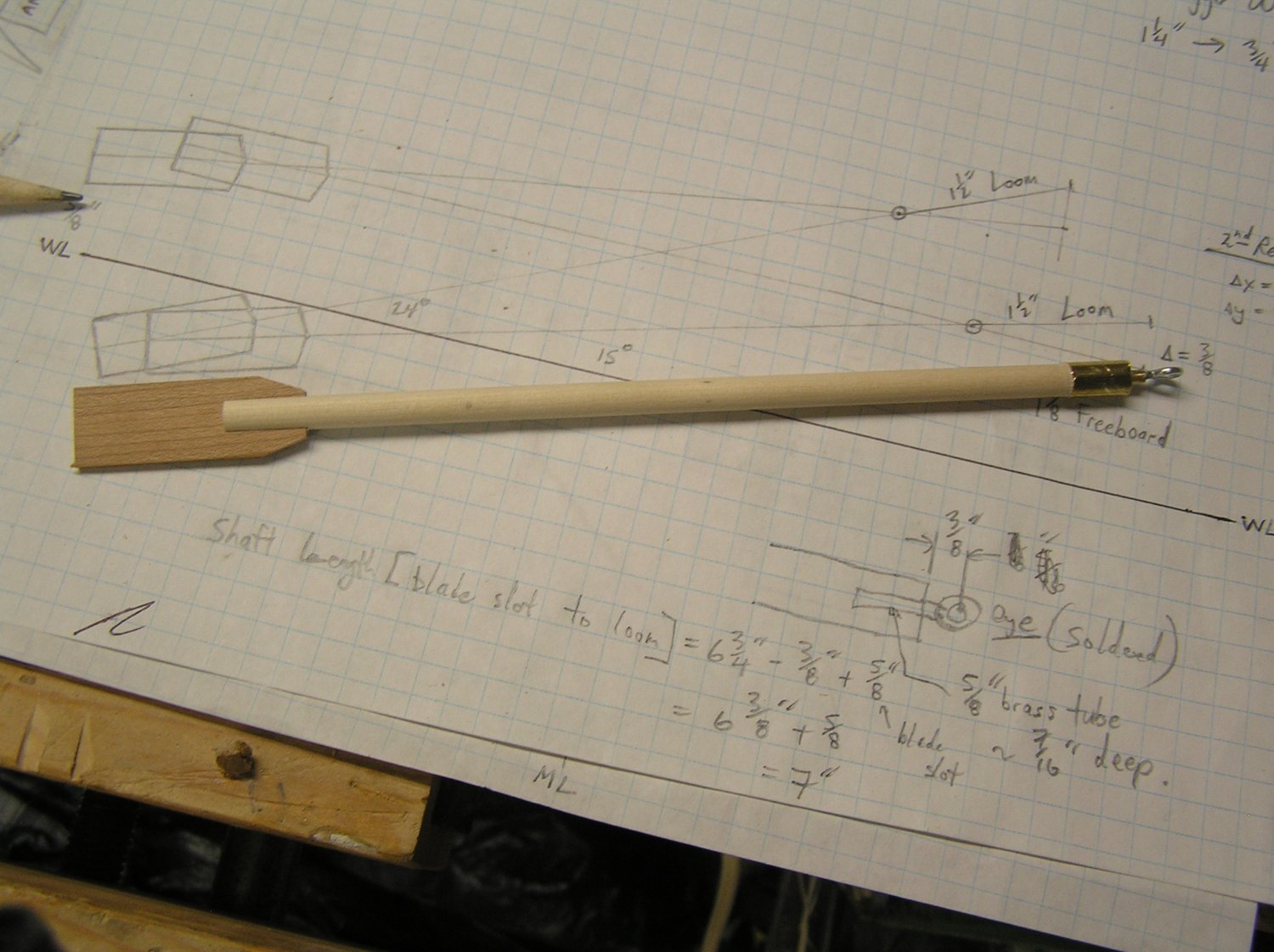
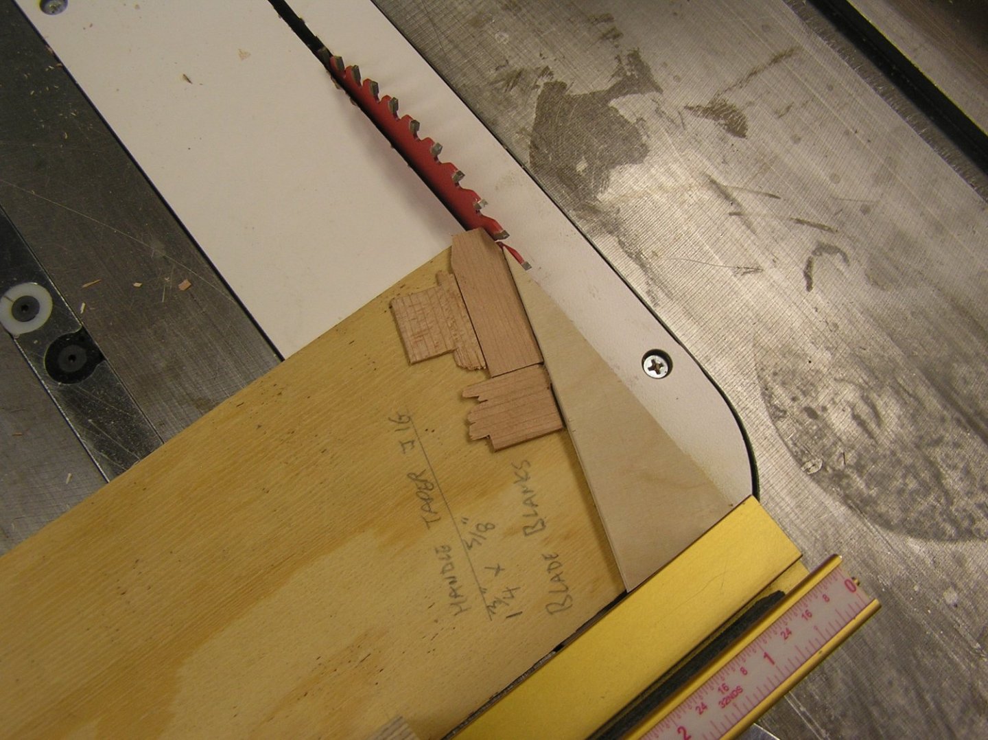
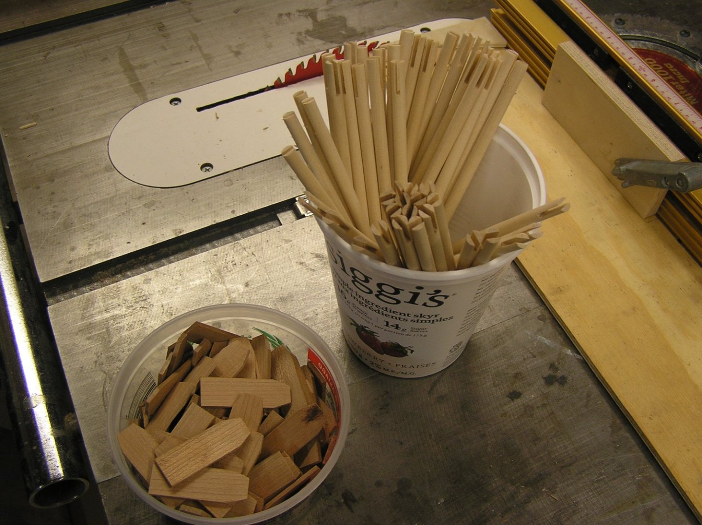
Beautiful weather, warm days and cool nights. Perfect for cycling along the canal. Despite this I have managed to make a start on the oars with the aid of some sophisticated jigs 😆. Problem one was to cut a slot centred in the end of the 1/4" shaft, in which to insert a blade. I got a thin-kerf blade for this. Below is the jig; first three holes were drilled during hole/kerf alignment. Labelled three holes are to hold the shafts, in whichever suits since dowel varies a little. Just press the dowel down until it hits the plywood layer at the bottom (hidden, and which is not drilled through). Next problem is to drill a centred 1/8" hole at loom end of shaft. Jig consists of a piece of wood clamped to the drill press table. Drill a 17/64" hole through it, then change bit to 1/8". Insert shaft into hole from below and drill to depth. Next chore - cut consistent chamfers at handle end of blades. Another sophisticated jig. Here are shaft and blade blanks. There are about 100 blades (more than enough) but I'll need to make more shafts. Finally, a pressed-together oar, so far. The screw eye is soldered into a bit of 1/8" brass tube which will be epoxied into the shaft hole. This extension will prevent the edge of the oar mounting strip on the beam from interfering with the shoulder of the wood shaft at rotation limits. The brass ferrule is pressed on to prevent cracking of the shaft. You can see I added some length to the blades compared to the drawing since they were just too stubby-looking, while maintaining the blade-to-loom pivot length. This blade is the same size as I tested for sweep pull force before; I had reduced it in the drawing to keep overall oar length at what Pitassi states. But now I'm OK with lengthening it slightly. Now wondering what to do about the squared shaft ends in middle of blade. I tried sanding bevels on one test piece but couldn't get even those two edges consistent, never mind over 88 oars. Might just leave or might do another jig.


- 536 replies
-
- 4
-
-
-
- Quadrireme
- radio
- (and 1 more)